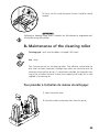
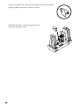
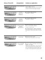
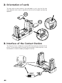
1
User’s Guide
Printer for
Plastic Cards
Quantum User’s Guide. Part Number : A5405. Rev. A
May 2003 © Evolis Card Printer
DECLARATION OF CONFORMITY
CONCERNING SAFETY AND
ELECTROMAGNETIC COMPATIBILITY
Name of the manufacturer : Evolis Card Printer
Adress :
29, avenue de la Fontaine
Z.I. Angers Beaucouzé
49070 Beaucouzé
France
Material designation :
Quantum printer
I, the undersigned,
Mr. Serge Olivier, Technical Manager
Declare that I have received the assumption of the above material, used
and installed in accordance with the notice, with the essential requirements of Directives 73/23/CEE and 86/336/CEE, modified by 92/31/CEE and
93/68/CEE by the application of the following regulations :
EN 60950 of January 1993 + A1 / A2 / A3 / A4
EN 55022 Class B of 1998
EN 55024 of 1998
EN 61000-3-2 of 1995
EN 61000-3-3 of 1995
Beaucouzé, April 2003
Table of contents
Introduction
Chapter 1 • Setting out
1. Choice of a location
2. Unpacking the printer
3. Description of the printer and its functions
4. Installation of the interface and the supply cable
5. Installation of the ribbon
6. Card management
a) Configuration
b) Loading the cards
c) Removal of printed cards
d) Reject Card Boxes
7. Other stages of installation
3
5
6
8
11
12
11
11
22
22
22
Chapter 2 • Printing
1. Driver installation
2. Configuration of the printing parameters
3. Printing
33
33
33
Chapter 3 • Cleaning
1. Cleaning the interior of the printer
2. Cleaning the print head
3. Cleaning of the cleaning roller
22
22
22
Chapter 4 • Assistancee
1. Interpretation of the printer control panel
2. Printing and interpreting a test card
3. Printing quality problems
4. Resolving card jamming
5. Changing a print head
6. Customer assistance
22
22
22
22
33
33
Chapter 5 • Technical specifications
33
Chapter 6 • Evolis Guarantee
33
Chapter 7 • Supplies
33
Appendix A Magnetic encoding
33
Appendix B Smart Card Contact Station
33
3
Introduction
We congratulate you for choosing a Quantum printer!
The Quantum printer is the ideal solution for printing your plastic cards in areas such
as Office Services, identification, access control and all other applications required
large volume card printing …
This product is accompanied by a wide range of assistance services from the company
Evolis and its partners, specially chosen to help you effectively and professionally.
4
Chap.1
Setting
1. Choice of a location
The Quantum printer must be set up on a strong, flat surface, capable of supporting the whole weight of the printer and its loaded supports (cards and ribbon).
The printer must be accessible from all sides for installation and use.
WARNING !
The printer weighs 25 kg (55lbs) without the consumables installed. It is therefore wise to be helped by another person when lifting and moving it.
2. Unpacking the printer
To unpack the printer, proceed as follows :
1. Remove the upper protective foams.
2. With another person, lift the printer out of its cardboard and place it in the
selected location.
3. Remove any adhesive from the outside of the printer.
NOTE !
It is best to keep all the packing materials in case the printer has to be moved or
returned for any reason.
The following elements are provided with your Quantum printer :
Two weights
■ One supply and one supply cable
■ One printer interface cable
■ One user’s guide (this guide)
■ A Quantum CD (Drivers & Documents)
■ A cleaning kit
■
If any of these elements are missing from your set, please contact your Evolis reseller.
5
3. Description of the printer and its
functions
We invite you to see the different components of your printer marked on the following drawings, which we refer to in this manual.
G
B
D
A
J
E
C
F
i
H
A.
B.
C.
D.
E.
F.
G.
H.
I.
Feeders 1 & 2
Flip Over Module
Reject Boxes 1 & 2
Output Hoppers 1 & 2
Thermal print head
Control panel
Two cleaning rollers
Identification label
Connection
Connector
Switch
Parallel port
USB port
DB-9 connector
J. Cover lever
6
C
Receives the card for printing
Rotate the card 180°
Collect the faulty cards
Collect the cards leaving the printer
Enables the cards to be printed.
Indicates the activity of the printer.
Remove all possible dust before the card is printed.
Indicates the model and serial number of the printer.
Enables the printer to be connected to its supply source.
Turns on and off.
Enables data to be received "from" and sent
"to" the computer.
Enables data to be received "from" and sent "
to" the computer.
Enables a coupler for chip cards to be connected
Enables the printer cover to be opened and closed.
Printer control panel
A control panel is available on the upper top of the printer.
Four LED’s are associated with symbols indicating the current activity of the printer.
These LED’s indicate :
Push button
Cleaning signal
Lack of cards in the feeders of output hoppers full
End of ribbon
Switch on, data reception
NOTE !
Refer to section 4 of this manual for further information on the interpretation
of the messages of the control panel.
4. Installation of the interface and
supply cables
WARNING !
Make sure that the printer switch is at 0 (OFF).
7
1. Connect the interface cable supplied with your printer as shown above
2. Connect the other end of the cable to the corresponding port of your computer
3. Connect the supply cable to the supply and then connect the connector of the supply cable to the printer
4. Then connect the end of the supply cable to an earthed mains socket
5. Turn on the printer as follows :
The green LED’s from the control panel lights and the print head rises and falls,
indicating that the mechanical operation of the printer is correct.
If the green LED’s fails to light, this means that the installation has not been carried out correctly or even that the operation of the printer is faulty. Check the
installation.
IMPORTANT !
This product is turned off by disconnecting it from the mains, which must remain
accessible.
This product must be connected to an electrical installation that is correctly protected and earthed
5. Installing the ribbon
1. Open the printer cover by pressing the cover lever, then pivoting it.
IMPORTANT !
2. Install the ribbon in the printer as indicated and then close the printer cover.
8
The ribbon must be correctly installed for the printer to work. Only use Evolis
ribbons. Evolis declines all responsibility if the printer or the print head is damaged through the use of an unapproved ribbon.
The ribbon is set automatically when the cover is closed.
6. Card management
a. Configuration
The Quantum printer has two card feeders and two card output hoppers which
may all work independently of the others. To this effect, there are four ways to
manage the loading and reception of the cards. The different modes may be set
from the properties of the Quantum printer driver (see chapter 2 for more information on the configuration of the printer driver).
Configuration of the feeders
• Automatic selection
The cards are taken alternately from feeder 1 then from feeder 2 until there
are none left.
When an error is detected in one of the feeders, the cards are taken automatically from the other feeder.
• Alternating mode
The cards are taken alternately from feeder 1 then from feeder 2 until there
are none left.
When an error is detected in one of the feeders, the printer stops and a printer internal error is displayed on the printer control panel.
• Feeder 1
The cards are only taken from feeder 1 until it is empty.
• Feeder 2
The cards are only taken from feeder 2 until it is empty.
Configuration of the output hoppers
• Automatic selection
The cards are received alternately in hopper 1 and then hopper 2.
When an error is detected in one of the hoppers, the cards are received in the
other hopper.
• Alternating mode
The cards are received alternately in hopper 1 and then hopper 2.
When an error is detected in one of the hoppers, the printer stops and a printer internal error is displayed on the printer control panel.
9
• Output Hopper 1
Hopper 1 receives the cards from the feeder pre-defined in the feeder configuration in the driver.
• Output Hopper 2
Hopper 2 receives the cards from the feeder pre-defined in the feeder configuration in the driver.
b. ) Loading the cards
The Quantum printer has two feeders that can contain a maximum 500 cards
each (0.76 mm – 30 mil.).
A label placed inside each feeder
enables them to be identified :
Feeder 1 and Feeder 2.
NOTE !
The configuration of the feeders may be set from the properties of the printing driver. See point 2 of chapter 2 of this manual for further information on
their use.
1. Open the door of the feeder as
indicated and insert 500 cards max.
(0.76 mm – 30 thou.). Note the position of the pre-printed cards.
10
2. Ensure that the stack of cards is
correctly aligned on the edge of
the feeder.
3. Place the weight provided with the
printer on the cards as shown.
4. If necessary, insert a maximum 500 cards (0.76 mm – 30 thou.) in feeder 2,
repeating the operations noted in points 1, 2 and 3
5. Ensure that the doors to feeders 1 and 2 are completely closed.
IMPORTANT !
Card thickness : The Quantum printer only accepts cards with a thickness of
0.76 mm (30 mil).
Advice concerning the selection of cards :
• Only use the type of cards appearing on the Technical Specifiactions
chapter of this manual
• Do not touch the printable surface of the cards ; the printing quality
depends on this
• Do not use damaged or folded cards or with a texture in relief
• Always stock blank cards in a clean, dust-free loaction
11
c. Removal of printed cards
The Quantum printer has two output hoppers with a capacity of 500 cards each
(0.76 mm – 30 thou.) devoted to receiving the printed cards. Note that the first
printed card is on top of the cards.
NOTE !
The configuration of the output hoppers may be set from the properties of the
driver. See point 2 of section 2 of this manual for
further information on their use
1. 1. Open the door of the output hopper as indicated and remove the cards as indicated.
d. Reject Card Boxes
The Quantum printer is fitted with two reject boxes, each of which may
contain up to 25 cards (0.76 mm – 30 mil)
Reject box 1 is designed to receive :
- all faulty cards from feeder 1 or 2, depending on the configuration of the output hoppers established in the driver
- all used cleaning cards
- printed test cards
Reject box 2 is designed to receive :
- all faulty cards from feeder 1 or 2, depending on the configuration
of the output hoppers established in the driver
A card present in the flip over module or in the printing station is ejected into one
of the two reject boxes in the following cases :
■
■
■
■
12
Detection of a problem in transporting the card
Detection of the problem with the rising and lowering of the print head
Detection of a problem in the flip over module
Torn or cut ribbon
■
■
■
■
When switching the printer power on
Error of magnetic encoding (data writing or reading)
Error of personalisation of a smart card (data writing or reading)
Error of personalisation of a contactless card (data writing or reading)
NOTE !
A reject boxt contains a maximum 25 cards (0.76 mm - 30 mil). The excess cards
are ejected out of the printer.
7. Other stages of installation
You have now completed the installation (material) of your Quantum printer. For
the moment, we strongly advise you to continue to read this manual and we will
inform you that there are still two extra stages to be followed to make your
Quantum printer perfectly operational :
■
■
Installation of printer driver
Printer cleaning
13
Chap.2
Printing
1. Installation of the printer driver
Before using your Quantum printer, you must install its driver.
Remember : the driver and Quantum printer operate under Windows 2000, NT
4.0 and Xp.
NOTE !
The CD provided with the printer includes a utility which automates the installation of the printer driver. This utility installs the driver the right driver for your
configuration.
For Windows users :
1. Start Windows making sure that no other Windows application is running.
2. Put the CD in the Cd-rom reader of the computer.
3. When it starts, the CD shows a main menu. Click on the language required.
4. Click on the Driver Installation option of the menu. The driver is installed
automatically.
If the installation program does not work automatically, follow the
instructions below :
1. Start Windows making sure that no other Windows application is running.
2. Put the CD in the Cd-rom reader of the computer.
3. Click Start on the Windows bar, select Parameters and then Printers.
4. Double-click on the icon Add printer.
5. Click on Next until the list of manufacturers is displayed.
6. Click on Floppy disk supplied then on Install from …
7. Select the letter of the reader corresponding to your Cd-rom reader
8. Click on Continue.
9. In the tree of the Cd-rom reader, double-click on Driver list.
10. Double-click on the list corresponding to your Windows environment.
Windows.
14
11. Select the file “younof.inf”.
12. Click on OK. the name of the printer manager appears.
13. Continue the installation by following the instructions displayed on the screen.
Note that when you install the driver manually as above, the option “Dialog with
printer” in the “Tools” tab is disable.
The installation of a driver under Xp / 2000 may be subject to the authorisation of
the administrator in its "login system" function.
IMPORTANT !
If your printer is connected via a parallel interface cable, the driver installation
is now complete.
If your printer is connected via a USB interface cable, go to the following section
“For Windows users with a USB interface” and follow the instructions.
For Windows users with a USB interface :
1. Install the driver following the instructions supplied in the preceding section
For Windows users.
2. Install the USB driver :
■ Check that the Quantum printer is turned on.
■ Connect the USB interface cable to your computer and then to the appropriate printer port.
■ The window Add New Material Assistant appears. Click on the Next button.
■ Click on the option that invites you to seek the best driver for your peripheral
and then click on Next.
■ Select the option Cd-rom reader and click on Next.
■ Choose the list corresponding to the Windows environment (NT 4.0, Xp or 2000).
■ Click on Next. The USB has now been installed.
■ Follow the instructions displayed on the screen.
Checking/selecting the printer port
1. Having turned your computer on and off, clock on Start and in Parameters
select Printers
2. In the Printers window, select the Evolis Quantum icon.
3. In the File menu, select Properties.
4. Click on the Details tab (for W95/98) or Ports (for Xp/2000/NT) and select the
USB printer port from the list.
5. Click on OK to close this window. The configuration is complete.
15
2. Configuring the printing parameters
Before using your Quantum printer, it is recommeded to check / modify the
default parameters of the driver. Furthermore, if you have options installed, you
must declare them in the driver.
Your printer has a large number of functions that may be set in the printing manager. These printing parameters are accessible :
From Start in the Windows bar, Parameters then Printers
1. Select Evolis Quantum
2. In File in the menu bar of the Windows window, select Properties (for
Windows 95/98/2000) or Default Document (for Windows NT 4.0).
■
From your Windows software :
In File of the menu bar of your application, select Print or
Printing configuration.
■
Note that the procedures vary according to the type of software used and the
Operating system.
IMPORTANT !
Before using the printer, make sure that it has been correctly selected as a
default printer.
Selection of the Quantum as default
To select your Quantum printer as default, proceed as follows :
1. Click on Start, in the Windows bar select Parameters and then Printers.
2. Click on the Quantum icon and them point to File on the menu bar.
3. Select Define by default and close the window.
Definition of the properties of the Quantum printer
Different dialog boxes enable you to :
■ Make adjustment such as the card orientation and the printing quality.
■ Manage the different printing modes and the use of the right ribbons.
■ Select the printer port.
■ Activate the different functions of control, repair and cleaning of the printer.
16
Use of the on-line help
A help file guides you through the use of each of the printing management parameters in line with the different printing modes and criteria retained. In order to
familiarise you with these various parameters, we recommend that you consult
this help before making any changes.
"Characteristics" dialog box
This dialog box enables you to select :
Orientation :
the orientation of the printing in portrait or landscape and the
rotation of the printing to 180°
Feeders configuration :
the feeding mode of the cards
Output Hoppers configuration :
the reception mode of the cards
Copies :
the required number of copies of the card
"Graphic" dialog box
This dialog box allows the selection of :
Ribbon type :
the type of ribbon used
Configuration of the printing :
simple recto or recto verso printing, with the possibility of setting the ribbon panels.
"Tools" dialog box
This dialog box offers first level maintenance for your Quantum printer.
If your Quantum printer has an option with a magnetic encoder, configure it now
with the "Encoding Settings" button. For further information on this printing
option, consult Annexe A of this manual.
17
We would also recommend that you print a “Test Card”
at the time of the first use and keep it safely. This card
records the information that could be required if you call
the after-sales service.
Comment : The "Dialog with printer" option is only available if the printing driver has been installed using the
installation program of the CD.
“General” dialog box
This dialog box is a window of Windows information
that enables the printing of a test page only to control the communication between the computer and the printer.
“Details” dialog box
This dialog box is a Windows control window that enable the printer port to be
selected and validates the use of the appropriate printer driver. The displayed parameters must only be modified by a person with advanced competence.
“Color management” dialog box
This dialog box enables the printing to be associated with a defined profile for
color management.
3. Printing
A large number of windows applications allow a document to be printed (Word
– Access
– Excel, for instance). In order to familiarise yourselves with the setting up of a letter and the printer settings, we propose the following dual-sided printing example.
Under Microsoft® Word
After having registrated the Quantum printer
by default :
1. Run Word and in File, click on Page Setup.
2. The dialog box proposes :
■ “Paper format“ : select Youn Card
■ “Orientation” select Landscape
18
The “Margins” dialog box proposes “printing margins”
■ Select 0 cm for all margins
■ Then close the window by clicking “OK”
To obtain a document with 2 pages, click on “Insertion” then select “Jump” and
validate the option “Jump page”.
Your Word window should now appear as
follows :
You are ready to personalise your letter in
recto/verso by entering the various composition elements :
■ Logo and Illustration
■ Identity photo
■ Constant and variable texts (Identity)
■ Etc.
Exemple :
It should be noted that this example is not
intended to initiate the operator in the working of the Word application, it is only intended to establish a relationship between the
drawing of a letter and the Quantum management parameters necessary for the printing.
19
Evolis Quantum Printer Driver Settings
To access the parameters from the Word
window :
1. In the menu bar, point on File
and select “Print”
2. The dialog box indicates that the Evolis printer has been selected.
Click on Properties. The dialog box of the Evolis Quantum driver opens.
The printing parameters for this graphic example are :
1. “Main” dialog box select :
■ Orientation – Front side : landscape
■ Orientation – Back side : landscape
■ Feeder configuration : automatic selection
■ Vessel configuration : automatic selection
■ Copy (number to be determined)
2. “Graphic” dialog box, select :
■ In Ribbon type : “6 panel ribbon (YMCKOK)”
■ In Printer settings : “Print on both sides”
3. Click on Apply if you change a parameter, then on OK to close each successive dialog box.
4. Once back in the main window, click OK to run printing.
NOTE !
Consult the help in each dialog box, if necessary. See paragraph “Use of on line
help” above for further information.
20
Chap.3
Cleaning
Preserve the validity of your guarantee !
Not observing the cleaning procedures contained in this chapter may cause the
guarantee on your printer and print head to be annulled. The company Evolis
declines all responsibility if the printer is used in unapproved cleaning conditions.
Evolis places the following cleaning items at your disposal available under the reference article A5011 – UltraClean Cleaning Kit:
■ 5 Cleaning cards pre-saturated with isopropyl alcohol 99%
■ 5 Swabs with isopropyl alcohol 99%
■ 1 box of 40 pre-saturated cleaning cloths
1. Cleaning the interior of the printer
Cleaning cycle : every 1800 cards
Use : pre-saturated cleaning cards
When it is necessary to clean the interior of the printer (every 1800 inserted cards)
the Cleaning light comes on as follows :
Status after inserting 1800 cards
21
If the printer has not been cleaned after the Cleaning light has lit, it will begin to
flash when 450 supplementary cards have been inserted. In this case, the warning
light flashes as follows :
Status after inserting 2250 cards
WARNING !
If the cleaning cycle is not performed before the 2250th card is printed, the print
head warranty is void.
This simple cleaning system requires the use of pre-saturated cleaning cards specially conceived for the printer. A cleaning kit including card samples is delivered
with your package. The repeated passes of the card inside the printer clean the
card transport rollers, the cleaning rollers and the print head.
To clean the interior of the printer, proceed as follows :
1. Remove the ribbon from the printer then close the
cover.
2. Remove all the cards from
feeder 1.
22
3. Take a cleaning card and place it in feeder 1.
4. Press the push button from the control
panel for a few seconds. The cleaning
starts.
5. After a few seconds, the printer cleaning is performed and the used card is ejected into the reject
box 1.
IMPORTANT !
After performing a cleaning cycle, wait 2 minutes for the cleaning fluid to evaporate completely before using the printer again.
NOTE!
It is also possible to start a cleaning sequence without waiting for the cleaning
signal of the printer. This action is carried out by pressing the push button from
the Control Panel for few seconds. In this case, repeat operations 1, 2 and 3
above.
Although the cleaning signal has been activated, the printer will continue to work.
23
2. Cleaning of the print head
Cleaning cycle : each time you load a new ribbon
Use : cleaning swabs
The cleaning head is cleaned when cleaning the interior of the printer (see preceding section). However, in order to preserve the original printing quality and reduce the incidents caused by an excessive presence of ink on the surface of the print
head, it is recommended that you clean it regularly (every 1000 cards) using the
cleaning swabs provided with the UltraClean cleaning set.
ATTENTION !
It is very important to protect the print head and all other associated components from any electrostatic discharge.
The print head is a fragile element. To avoid damaging it :
■ Before cleaning the print head, disconnect the printer from the mains.
■ Respect the cleaning cycles
■ Never place the print head in contact with sharp of metal object.
■ Avoid direct contact of the surface of the print head with fingers.
Changed pint quality or even permanent degradation of the print
head could result.
To clean the print head, proceed as follows :
1. Open the cover of the printer and
locate the print head.
2. Take a new swab and
press on the stick to
let the liquid out.
24
3. Gently rub the swab along over the print head for several
seconds.
IMPORTANT !
Following a cleaning cycle, wait 2 minutes for the cleaner to evaporate entirely before using the printer.
3. Maintenance of the cleaning roller
Cleaning cycle : each time the ribbon is changed (1000 cards)
Use : cloths
Your Quantum printer has two cleaning rollers. Their adhesive surface holds the
dust when the cards are passed. Although these rollers are maintained with the
automatic cleaning of the printer, it is nevertheless advisable, for the perfect cleaning of the surface of the cards, to clean them regularly and simply with a cloth
supplied in the cleaning set.
Pour procéder à l’entretien du rouleau de nettoyage :
1. Open the printer cover
2. Locate the rollers and remove them from the printer
25
3. Clean the rollers with a cloth from the cleaning set. Eliminate all dust
by gently rubbing the whole surface of the roller.
4. Replace the roller in the printer once dry and
then close the printer cover.
26
Chap.4
Assistance
To satisfy the needs of its customers as far as possible, Evolis provides a full
range of technical assistance available in this manual and on the internet site
www.evolis.com.
This section gives information concerning the first level repairs of the Quantum
printer.
1. Interpreting the messages of the
control panel
Although the Quantum printer has been conceived to work very reliably, some
problem might, however, arise. The following section helps you to identify the
cause of all possible problems in the installation or in the use of the printer and to
find the way to resolve them.
Description of the printer control panel
A Control Panel is available on the top of the printer.
Four LED’s are associated with symbols indicating the current activity of the printer.
Switch on,
data reception
End of ribbon
No card in the feeders or full
output hoppers
Cleaning
signal
Pushbutton
27
These LED’s indicate :
The LED’s on the control panel are represented in one of the following states :
The push button allows re-initialisation in case of :
No card in feeder 1 or feeder 2
■ Internal printer problem
■
The push button also enables :
■
■
a test card to be printed (see point 2 of this section)
a cleaning cycle to be launched (see point 1 of section 3)
Consult the following conditions of the control panel to determine the activity of the
Quantum printer or the nature of the problem :
Status of the LED’s
Interpretation
PRINTER READY
DATA TREATMENT
END OF RIBBON
Solution or explanation
The printer is ready to receive data
The printer is receiving data from one or several of its interfaces
■ there
is no ribbon in the printer
the ribbon has finished
■ the ribbon has been uncorrectly installed in
the printer
■
Check the status of the ribbon in the printer. If you
have a printing job in course, this starts again with
a new card
ABSENCE OF CARD IN
THE FEEDER/S
28
■
there is no card in the feeder/s
Empty the hopper/s and then press the push
button for one second. The printing starts
again
Status of the LED’s
Interpretation
Solution or explanation
OUTPUT HOPPER/S FULL
output hoppers is/are full
Empty the hopper/s and then press the push button for one second. The printing starts again.
CLEANING
(AFTER 1000
INSERTIONS)
■
■
CLEANING
(AFTER 1500
INSERTIONS)
PRINTER INTERNAL
PROBLEM
(MECHANICAL)
The printer needs cleaning
See chapter 3 “Cleaning “
The printer needs cleaning
See chapter 3 “Cleaning “
■ There is jamming on the card in the printing
post or in the flip over module
See point 4 of this section
■
A mechanical part is faulty in the printer.
Press the push button for one second. If the problem persists, call your Evolis reseller for assistance.
COVER OPEN
OUTPUT HOPPER/S
DOOR OPEN
■ The
printer cover is open
Close the cover. The activity in course restarts.
One or some of the door/s of the output
hopper/s is/are open.
■
When a door of the hopper/s is open, the printer
continues the printing in course and the card is
then stocked under the destination hopper. Close
the door/s of the hopper and the activity restarts.
29
Status of the LED’s
Interpretation
MAGNETIC CODING
ALERT
(ALTERNATING
FLASHING)
Solution or explanation
■ The orientation of the magnetic track in the
feeder/s is not correct
■ The type of encoding is not correctly set
(HICO or LOCO).
See annexe A of this manual for information.
■ ∑ The encoded data are not conform with
the ISO 7811 standards or are not conform
with the parameters predefined in the properties of the driver.
See annexe A of this manual for information.
Press the push button for one second. The
printer restarts the magnetic encoding cycle
three times with the same card and if the
problem still occurs the same, it tries with two
new cards. If the problem persists, call your
Evolis reseller for assistance.
PRINT HEAD
COOLING SYSTEM
(SIMULTANEOUS
FLASHING)
■ The
printer head cooling system is active.
The printer stops working after a few seconds.
When the print head has returned to its normal
working temperature, the activity is restarted.
2. Printing and interpretation of a test
card
The printing of a test card enables certain technical information to be collected on
your printer and to validate its good operation.
We advise you to print it as soon as your printer is put into service and to keep it
close at hand.
Printing a test card
1. Make sure there is a ribbon in the printer
2. Turn off the printer.
3. Push the pushbutton on the control panel
4. Turn on the printer while holding down the push button
5. The green warning light on the control panel lights.
6. Release the button as soon as the green warning light flashes.
7. A test card is printed in a few seconds (in color if printer has a color ribbon
installed or in single color if it is fitted with a monochrome ribbon).
8. The printed card is ejected into reject box 1.
30
Interpretation of a test card
The printing of a test card gives the following information :
■ Correct printing of the colors and single color
■ The correct positioning of the ribbon in the printer
■ The printer model
■ The printer serial number
■ The version of the Firmware installed in the printer
3. Printing quality problem
The following information will help you to resolve any possible problems with
printing quality that might arise when you use your printer. If, despite this information, you are unable to resolve the problem, contact your Evolis reseller.
Nothing prints
1. Check the supply
Make sure that :
■ the supply cable is correctly connected to the printer and to a socket that
works.
■ the printer is turned on (position 1). The green LED on the control panel
must be alight.
■ the supply used is that delivered with the printer
2. Check the card feeder and the card in the printer
■ Check the presence of cards in the feeder.
■ Make sure there is no jamming .
See point 5 of this section
3. Check the ribbon
■ Make sure the ribbon has been correctly installed and
that the printer cover is well closed.
4. Print a test card
See point 2 “Printing and interpretation of a test card” in this section.
5. Check the printer interface cable
■ Check the connection to the computer and to the printer.
■ Test with another cable of the same type.
6. Check the printing driver
■ Make sure that the driver of the Quantum printer is present in the
Windows settings
31
7. Check the printing parameters of the computer
■ Make sure that the Quantum printer has been selected as the default printer.
See “”Configure the printing parameters” in the Printing chapter.
8. Check the configuration of the network
If your printer is connected in a network, make sure that it is correctly configured in the network environment. See the documentation concerning your
network for further information.
A clean card is ejected
1. Check the ribbon
■ Make sure the ribbon has not finished or been cut. Replace or reinstall the
ribbon if necessary.
2. Check the interface cable of the printer
■ Check the interface cable of the printer
■ Check the connection to the computer and to the printer.
■ Test with another cable of the same type.
3. Elements of the printer might have been damaged.
■ Print a test card.
See point 2 “Printing and interpretation of a test card” in this section.
If the test card fails to print, contact your reseller for a printer head replacement
The printing quality is not satisfactory
1. The contrast and brightness settings must be changed
■ Lack of contrast and color saturation, increase the contrast and brightness
settings in the configuration of the printing driver.
2. The type of cards used may be inappropriate
■ Make sure the type of cards used corresponds to the specification
See section “Technical Specifications” in this manual for further information.
■
■
32
The card texture is rough or not completely smooth.
Try printing with another kind of card.
Partial or incorrect printing
1. Check the settings defined for the printing
■ Make sure that no element of the pagination is outside the printing margins
■ Check the orientation of the document selected in the configuration of the
printing driver (Landscape or Portrait)
2. Check the printer interface cable
■ If unusual characters appear, make sure you are using the right interface
cable for your printer.
■ Check the connection to the computer and the printer.
■ Test with another cable of the same type.
3. Check the cleanliness of the printer
■ Clean the interior of the printer, the cleaning rollers and the print head if
necessary.
See section 3 Cleaning” of this manual.
4. Check the card cleanliness
■ Make sure they have been stored in a dust-free place.
5. Check the cleanliness of the print head
See the cleaning procedure of the print head in section 3 “Cleaning”.
6. Check the ribbon
■ Its placement in the printer.
■ Its correct running
7. Check the print head
■ If horizontal lines (white) appear on the card, elements of the print head
may be jammed or damaged.
■ Clean the print head.
See section 3 “Cleaning” for more information.
■
If the problem is not resolved after cleaning, contact your reseller for a
replacement cleaning head.
4. Correcting card jamming
In the printing station :
Remove the card as follows :
1. Open the printer cover and remove the ribbon.
2. Remove the card by pushing it manually towards the printer outlet. In the presence of several cards, push the top one first.
3. Refit the ribbon and close the printer cover.
4. Press the pushbutton on the control panel.
33
In the slip over module :
Remove the card as follows :
1. Turn off the printer (position 0)
2. Unscrew the screw and remove the two seals as indicated opposite
3. Remove the card from the flip over by
turning the flip if necessary.
4. Refit the two seals.
5. Turn on the printer once more (position 1).
To prevent card jamming :
1. Make sure that the thickness of the
card used corresponds to the specifications in the section "Technical
Specifications " of this manual.
2. Make sure that the cards are not
swollen.
3. Make sure that the cards are not stuck together.
5. Changing a print head
The print head of a printer is changed easily and effectively without any need for
tools or any special adjustment.
WARNING !
Before changing a print head, make sure that the printer has been turned off
(position 0).
Stage 1
Removal of the faulty print head
34
1. Open the printer cover and locate the print head.
1
2. With one hand, push the
metal piece located at the
back under the cover and,
with the other, turn the
two forks to release the
print head from the head
arm.
2
3. Disconnect the two cables located behind the print head
Stage 2
Installation of the new print head
1. Insert the two cables
in their housing
1
2
2. Insert the head vertically in the two guides
3
3. Turn the printer head to clip it in the metal piece.
35
4. Close the printer cover. The printer head is now installed.
Stage 3
Parameterising the new printer head
1. Make sure that the printer is turned on (position 1) and connected to a computer on which the printing driver of the Quantum printer is installed.
2. In the properties of the printing driver, click on the “Tools” dialog box.
3. In the section “Dialog with printer” enter the following : Pkn;x
x = the print head kit number written on a transparent label on the print head
Example : if the print head kit number is: 179-004-00048, the following command must be entered : Pkn;179-004-00048
WARNING !
If the print head kit number has not been correctly entered, the printer may not
work properly.
The new print head has now been parameterised. You can reuse your Quantum
printer.
6. Customer assistance
The suggestions given before in this section do not enable all problems to be resolved, connect to the evolis.com site for further information or contact your Evolis
reseller.
Evolis Internet site
www.evolis.com
If you need extra technical help, you will find a lot of information concerning the
use and repair of the Evolis printers in Support & Services on the Evolis internet site.
This enables you to load the latest versions of the Firmware, the drivers and the
user manuals, videos of use and cleaning of Evolis printers and an FAQ section.
36
Access to an Evolis reseller
For all unresolved technical problems, contact an Evolis reseller. If you do not know
of one, connect to www.evolis.com and send your request.
Evolis will direct you to your nearest Evolis reseller.
When you call an Evolis reseller, you must be near your computer and be ready to
supply the following information :
■ The
type and serial number of your printer
type of configuration and the operating system you use
■ A description of the incident that has been caused
■ A description of the steps you have taken to resolve the problem
■ The
37
Chap.5
Technical specifications
Printing mode
Color Dye Sublimation and Monochrome Thermal Transfer
Edge-to-edge printing as standard
Printer specification
Integrated ribbon saver
Printing speed
140 cards/hour in color (YMCKO), one side
110 cards/hour in color (YMCKO/K), two sides
Up to 1000 cards/hour in monochrome, one side
Resolution
300 dpi
Drivers
For Windows™ NT 4.0/2000 et Xp
Guarantee
Printer: 1 year
Print head: 1 year 1 or 500 000 passes
Type of ribbons
6 Panel Color Ribbon (YMCKOK) : 800 cards/roll
5 Panel Color Ribbon (YMCKO) : 1000 cards/roll
5 Half-Panel Color Ribbon (YMCKO) : 400 cards/roll
Monochrome Ribbon (KO) : 500 cards/roll
Monochrome Ribbon, black: 5000 cards/roll
Other Monochrome Ribbons: 1000 cards/roll
(available in black, blue, red, green, white, gold, silver
and scratch off)
Hologram Ribbon : 350 cards/roll
Other printer models
Quantum MAG
Printer with HICO/LOCO magnetic encoder – ISO 7811
Quantum SMART
Printer with Smart Card Contact Station – ISO 7816-2
Quantum Contactless
Printer with encoder/reader for contactless cards
(available on study)
Types of cards
Cards in PVC and Composite PCV cards
Format of cards
ISO CR-80 (53.98 mm x 85.60 mm - 3.375" x 2.125")
Thickness of cards
0.76 mm (30 mil)
Feeder capacity
1000 cards (0.76 mm-30 mil)
Output hopper capacity 1000 cards (0.76 mm-30 mil)
38
Printer dimensions
Height : 510 mm (20.07")
Length : 700 mm (27.55")
Depth: 300 mm (11.81")
Printer weight
25 Kg (55 lbs)
Connection
USB and parallel Centronics (cables supplied)
Supply
110~230 Volts AC, 60~50 Hertz
Environment
Working temperatures Min / Max: 15°C / 30°C
Humidity : from 20% to 65% without condensation
Stocking temperatures Min / Max: -5°C / +70°C
Stocking humidity : from 20% to 70% without condensation
Working ventilation : open air.
1 Clause related to the use of Evolis consumables
39
Chap.6
Guarantee
Several factors can affect the guarantee of the Evolis Quantum printer, particularly the use of consumables and non conform cleaning. Carefully read the conditions of the guarantee of the printer described below.
Conditions of guarantee
Evolis guarantees its printer against all manufacturing faults for a period of one
year counting from customer purchase. Customers must be able to demonstrate
the purchase or must register their product on the www.evolis.com internet site.
Evolis guarantees the print head for a period of one year or 500,000 passes (equivalent to 100,000 color cards or 500,000 single color cards).
The Evolis guarantee only covers problems arising in the course of normal use of
the printer and does not apply in the following cases :
- Non observance of the installation instructions described in the printer manuals
- Cleaning of the printer and/or print head not conform with the instructions described in the printer manuals (chapter 3)
- Use of uncertified Evolis consumables. For instance, the use of uncertified Evolis
ribbons may affect the quality and reliability of the printing works, by causing
poor quality printouts, or may even affect the operation of the printer. The guarantee covers no material damage or quality problem caused by the use of
uncertified Evolis ribbons
- All printer modifications or adaptations not expressly reported to and approved
by Evolis
- The use of options not manufactured / supported by Evolis
- The use of printing support (cards) not support by Evolis
- The resending of the printer in any packing that is not the original packing
If during the guarantee period Evolis is informed of a material fault, Evolis will proceed to repair or replace the product in question, at its own discretion.
Evolis is not bound by any obligation to repair, replace or reimburse while the customer does not return the faulty product to Evolis.
40
If Evolis is unable to repair the faulty material covered by the guarantee, Evolis will
proceed to replace it with a new or second hand product as long as the functions
are at least the same as those of the original product it replaces.
If the customer has signed an extension of the Evolis guarantee, Evolis will repair
the faulty material according to the clauses of the contract. To underwrite an
extension of the Evolis guarantee, contact an Evolis reseller.
No goods may be returned to Evolis without an RMA (Return Material
Authorisation) number. To obtain an RMA number, contact an Evolis reseller.
For all goods returns, the Evolis reseller may ask the customer to provide proof of
purchase of the material.
The customer is responsible for all damage caused in resending in unsuitable packing. Evolis may refuse to accept reception of the goods.
41
Chap.7
Supplies
list of supplies available from Evolis resellers.
Single color ribbons
Ref. R2121
Ref. R2011
Ref. R2012
Ref. R2013
Ref. R2014
Ref. R2015
Ref. R2016
Ref. R2017
Ref. R2018
Black Monochrome Ribbon
5000 cards/roll
Black Monochrome Ribbon
1000 cards/roll
Blue Monochrome Ribbon
1000 cards/roll
Red Monochrome Ribbon
1000 cards/roll
Green Monochrome Ribbon
1000 cards/roll
White Monochrome Ribbon
1000 cards/roll
Gold Monochrome Ribbon
1000 cards/roll
Silver Monochrome Ribbon
1000 cards/roll
Scratch off Monochrome Ribbon
1000 cards/roll
Multi-panel ribbons
Ref. R3114
Ref. R3111
Ref. R3013
Ref. R3012
42
6 Panel Color Ribbon
YMCKOK (Yellow, Magenta, Cyan, Black TT, Varnish and Black TT)
800 cards/roll
5 Panel Color Ribbon
YMCKO (Yellow, Magenta, Cyan, Black TT and Varnish)
1000 cards/roll
Half-Panel Color Ribbon
YMCKO (Yellow, Magenta, Cyan, Black TT and Varnish)
400 cards/roll
2 Panel Color Ribbon
KO (Black TT and Varnish)
500 cards/roll
Hologram ribbon
Ref. R4001
Optoseal® hologram ribbon
350 cards/roll
Hologram ribbon
Ref. A5011
Ref. L8001
UltraClean Cleaning Kit
5 pre-saturated cleaning cards, 5 swabs,
1 box of 40 pre-saturated cloths
eMedia Pro Software
Software for conceiving and editing badges with connection
to databases
43
Annexe A
Magnetic encoding
Introduction
Quantum printers with a magnetic stripe encoder are called Quantum Mag printers.
The working of a Quantum Mag printer is identical to that of a Quantum printer.
The magnetic encoder encodes tracks ISO 1, 2 and 3 in a single pass and then
checks the data.
Parameterisable in high coercivity (HICO) or low coercivity (LOCO) by a simple click
from the Windows driver, the encoders of the Quantum Mag printers are sent
adjusted by default in high coercivity (HICO), unless otherwise specifically ordered.
1. Location of the magnetic encoder
The magnetic encoder is a module installed in the
factory on Quantum Mag printers. The writing and
reading head is placed in the route of the cards and
after the print head.
NOTE !
The encoding sequence of a card is always carried out before printing
44
2. Orientation of the cards
Cards with a magnetic track must be installed in the feeder so that the magnetic track is near the low and as close as possible to the back of the printer (see
opposite) :
0,8 mm
0,5 mm
1 mm
0,25 mm
3. Windows Driver Settings
When first installing the Windows driver, it is necessary to set the functions of the
magnetic encoder. The functions of the magnetic encoder are accessible from the
"Tools" dialog box of the printing driver by clicking "Encoding Definition".
“Magnetic Encoder” dialog box
The “Magnetic Encoder” dialog box opens on selecting the "Encoding Definition"
button.
Track format allows the choice of the required ISO standard for each track. See
table in point 4 of this annexe for information concerning the ISO 7811 standards.
Coercivity sets the magnetic encoder in high (HICO) or low (LOCO) coercivity. A
magnetic track encoded in high coercivity is better able to withstand external disturbances than a magnetic track encoded in low coercivity.
Direct encoding enables the direct encoding of one or several magnetic tracks
from this window by simply selecting them and entering the data to be encoded.
Click on the " Encode " button to launch the encoding cycle.
Automatic extraction allows magnetic track cards to be encoded from applications
under Windows (like Word, for instance). A text field surrounded by the characters “|” and “|” (or other characters that might be defined by the user) will be
interpreted as an encoding command by the printing driver.
45
IMPORTANT !
Only use magnetic stripe cards conform to ISO 7810 and ISO 7811.
To work correctly, the magnetic stripe must be ground into the card.
Never use a card with an affixed magnetic track.
4. Cleaning the magnetic encoder
LThe magnetic encoder head requires regular cleaning in order to assure the integrity of the data encoded on the cards.
The magnetic encoder is cleaned when the printer is the object of a cleaning
sequence with pre-saturated cards (refer to chapter 3 " Cleaning " in this manual
for further information).
Repeated passing of the cleaning card inside the printer cleans the card transport
rollers, the cleaning rollers, the print head and the writing / reading head of the
magnetic encoder.
If between two printer cleaning sessions (every 1000 cards inserted), the reading/writing process has failed with more than one card, it is recommended to
start a manual cleaning sequence for the printer (refer to chapter 3 " Cleaning "
of this manual for the procedure).
5. ISO 7811 standard encoding
regulations
Track no
Field separator
Track density
Types of characters
Number of characters
Track 1
^
210 bpi
79
Track 2
=
75 bpi
Track 3
=
210 bpi
Alphanumerical
(ASCII 20- 95)
Numerical
(ASCII 48-62)
Numerical
(ASCII 78-62)
- Bit/s per inch
- Except the character " ? "
- Including the characters Start, Stop and LRC. These characters are generated automatically by the magnetic encoder
46
40
10.7
Annexe B
Smart Card Contact
Station
Introduction
The Quantum printers with a Smart Card Contact Station are called Quantum
Smart printers. The working mode of a Quantum Smart printer is identical to that
of a Quantum printer.
The Smart Card Contact Station of the Quantum Smart enables the chips to be
programmed according to ISO 7816-2 standards.
1. Location of the contact station
The Contact Station is a module installed in factory on
Quantum Smart printers.
The Contact Station is placed over the route of the cards and
after the print head. To come into contact with the station,
the chip card is placed under it and is pushed up mechanically.
NOTE !
The programming sequence of a chip is still carried out before the card is printed.
IMPORTANT !
Only use chip cards in line with the ISO 7816-2 standard.
Never print on the chip.
47
2. Orientation of cards
The chip cards must be installed in the card feeder in such a way that the chip
faces upwards and as close as possible to the inlet of the feeder (see drawing
opposite).
3. Interface of the Contact Station
The Quantum Smart is fitted with a female DB-9 connector on the back of the
printer. This connector, directly linked to the contact post inside the printer, is also
connected to an external coupling to program the chip.
,8 mm
0,5 mm
Port imprimante
Coupleur
externe
48
DB-9 connector pins
Card to chip contact points
1
2
3
4
5
6
7
8
9
C1 (V c.c.)
C2 (reset to 0)
C3 (Clock)
C4 (reserved)
C5 (mass)
C6 (Vpp)
C7 (E-S)
C8 (reserved)
C9 Mass when the chip is switched
with the contact post
A command sequence must be sent via the printer interface to insert a card in the printer and then place it under the station and establish contact.
The sequence of commands is described as follows :
Sending the Sis sequence : A card is moved from the feeder to the Contact Station and
stops under it.
The card is pushed up to come into contact with the station.
The printer links the contact post with the DB-9 connector.
The chip may be programmed via the series interface of
the computer and the external coupling.
NOTE !
See the programming guide of the Quantum printer to obtain more complete
information concerning the programming.
49
50
51