1
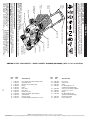
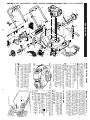
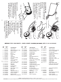
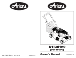
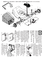
ARIENS ROTARY LAWN MOWER - - MODEL NUMBER A160H22 (96136600) (MFG. I.D. NO. 96146000800)
27
1
28
11
13 12
7
29
35
54
57
16
38
14
16
19
18
41
36
38
17
14
18
17
33
38
15
13
12
40
11
15
29
The operation of any lawn
mower can result in foreign
objects thrown into the eyes,
which can result in severe
eye damage. Always wear
safety glasses or eye shields while operating your lawn mower or performing any
adjustments or repairs. We recommend a
standard safety glasses or wide vision safety
mask worn over spectacles.
HOW TO USE YOUR LAWN MOWER
ENGINE SPEED
The engine speed was set at the factory
for optimum performance. Speed is not
adjustable.
ENGINE ZONE CONTROL
CAUTION: Federal regulations require
an engine control to be installed on this
lawn mower in order to minimize the
risk of blade contact injury. Do not under
any circumstances attempt to defeat the
function of the operator control. The blade
turns when the engine is running.
• Your lawn mower is equipped with an
operator presence control bar which
requires the operator to be positioned
behind the lawn mower handle to start
and operate the lawn mower.
TO OPERATE DRIVE SYSTEM
• To start forward motion, lift drive control bar up to handle.
• To stop forward motion, release drive
control bar.
IMPORTANT: Always keep drive control
fully engaged against handle when in use.
Operator
presence
control bar
DRIVE CONTROL ENGAGED
DRIVE CONTROL DISENGAGED
7
Plate tab
TO ADJUST CUTTING HEIGHT
Raise wheels for low cut and lower wheels
for high cut, adjust cutting height to suit
your requirements. Medium position is
best for most lawns.
• To change cutting height, squeeze adjuster lever toward wheel. Move wheel
up or down to suit your requirements. Be
sure all wheels are in the same setting.
NOTE: Adjuster is properly positioned
when plate tab inserts into hole in lever.
Also, 9-position adjusters (if so equipped)
allow lever to be positioned between the
plate tabs.
LEVER BACKWARD
TO LOWER MOWER
LEVER FORWARD TO RAISE MOWER Lever
Rear
door
Grass
catcher
handle
TO ATTACH GRASS CATCHER
1. Lift the rear door of the lawn mower
and place the grass catcher frame side
hooks onto the door pivot pins.
2. The grass catcher is secured to the
lawn mower housing when the rear
door is lowered onto the grass catcher
frame.
CAUTION: Do not run your lawn
mower without mulcher plate or plug, clipping deflector or approved grass catcher
in place. Never attempt to operate the
lawn mower with the rear door removed or
propped open.
Pivot pins
Catcher frame hook
TO EMPTY GRASS CATCHER
1. Lift up on grass catcher using the
frame handle.
2. Remove grass catcher with clippings
from under lawn mower handle.
3. Empty clippings from bag.
NOTE: Do not drag the bag when emptying; it will cause unnecessary wear.
39
NOTE: All component dimensions given in U.S. inches. 1 inch = 25.4 mm.
IMPORTANT: Use only Original Equipment Manufacturer (O.E.M.) replacement parts. Failure to do so could be hazardous, damage your lawn mower and void your warranty.
OPERATION
21547432
21547437
KNOW YOUR LAWN MOWER
54
57
READ THIS OWNER'S MANUAL AND ALL SAFETY RULES BEFORE OPERATING
YOUR LAWN MOWER. Compare the illustrations with your lawn mower to familiarize
yourself with the location of various controls and adjustments. Save this manual for
future reference.
21547486
21546914
21547473
21547658
Operator presence control bar
Handle knob
Gasoline filler cap
Fuel valve lever
Spark plug
Air filter
Drive cover
Wheel adjuster
(on each wheel)
36
38
40
41
These symbols may appear on your lawn mower or in literature supplied with the
product. Learn and understand their meaning.
Drive
control
bar
Starter
handle
Grass
catcher
Engine oil cap
with dipstick
Muffler
Mulcher door
Housing
Mulcher door – allows conversion to
discharging or bagging operation.
Drive control bar – used to engage
power-propelled forward motion of mower.
21547460
21546896
21547438
21547657
Drive Cover
Locknut, Hex
V-Belt
Kit, Wheel Adjuster, LH
(Includes Knob and Bearing)
Gear Case Assembly, Complete
Locknut, Hex 1/4-20
Spring
Kit, Wheel Adjuster, RH
(Includes Knob and Bearing)
Grassbag Assembly
Frame, Grassbag
28
29
33
35
1
7
11
12
13
14
15
16
17
18
19
27
21547462
21547513
21547455
21547525
21547484
21547482
21547485
21547471
21547636
21547504
21547475
21547478
Drive Control Assembly (Includes Cable)
Control Bar, Drive
Wheel & Tire Assembly, Front
E-Ring
Pinion
Dust Cover
Pawl, Drive
Washer, Flat 3/8
Bearing Assembly, Wheel Adjuster
Selector Knob
Retainer, Spring
Pan Head Tapping Screw #10-24 x 2-3/4
PART
NO.
DESCRIPTION
KEY
NO.
DESCRIPTION
PART
NO.
KEY
NO.
IMPORTANT: This lawn mower is shipped
WITHOUT OIL OR GASOLINE in the engine.
NOTE: Gasoline containing up to 10% ethanol (E10) is acceptable for use in this machine.
The use of any gasoline exceeding 10% ethanol (E10) will void the product warranty.
6
MEETS CPSC SAFETY REQUIREMENTS
Our rotary walk-behind power lawn mowers conform to the safety standards of the
American National Standards Institute and the U.S. Consumer Product Safety Commission. WARNING: The blade turns when the engine is running.
Operator presence control bar – must
be held down to the handle to start the
engine. Release to stop the engine.
Starter handle – used for starting engine.
ARIENS ROTARY LAWN MOWER - - MODEL NUMBER A160H22 (96136600) (MFG. I.D. NO. 96146000800)
ARIENS ROTARY LAWN MOWER - - MODEL NUMBER A160H22 (96136600) (MFG. I.D. NO. 96146000800)
8
1
4
52
46
39
32
30
41
29
41
38
28
41
71
34
25
51
43
53
33
55
45
11
36
42
56
31
16
53
37
10
35
48
49
50
REPAIR PARTS
36
12
26
14
26
47
12
12
21
9
40
27
15
20
6
37
56
69
68
34
57
18
19
55
44
24
28
30 29
32
5
6
2
25
27
59
3
7
64
58
31
17
BEFORE STARTING ENGINE
Gasoline
filler cap
ADD OIL
Your lawnmower is shipped without oil in
the engine. For type and grade of oil to
use, see “ENGINE” in the Maintenance
section of this manual.
CAUTION: DO NOT overfill engine with
oil, or it will smoke on startup.
1. Be sure lawnmower is level.
2. Remove oil fill cap/dipstick from oil fill
spout.
3. You recieve a container of oil with the
unit. Slowly pour the entire container
down the oil fill spout into the engine.
4. Insert and tighten oil fill cap/dipstick.
IMPORTANT:
• Check oil level before each use. Add oil
if needed. Fill to full line on dipstick.
• Change the oil after every 25 hours of
operation or each season. You may
need to change the oil more often
under dusty, dirty conditions. See “TO
CHANGE ENGINE OIL” in the Maintenance section of this manual.
Lower
mark
Oil fill cap /
dipstick
Upper
mark
ADD GASOLINE
• Fill fuel tank to bottom of tank filler neck.
Do not overfill. Use fresh, clean, regular
unleaded gasoline with a minimum of
87 octane. Do not mix oil with gasoline.
Purchase fuel in quantities that can be
used within 30 days to assure fuel freshness.
CAUTION: Wipe off any spilled oil or
fuel. Do not store, spill or use gasoline
near an open flame.
9
CAUTION: Alcohol blended fuels
(called gasohol or using ethanol or methanol) can attract moisture which leads to
separation and formation of acids during
storage. Acidic gas can damage the fuel
system of an engine while in storage. To
avoid engine problems, the fuel system
should be emptied before storage of 30
days or longer. Empty the gas tank, start
the engine and let it run until the fuel lines
and carburetor are empty. Use fresh fuel
next season. See Storage Instructions for
additional information. Never use engine
or carburetor cleaner products in the fuel
tank or permanent damage may occur.
TO STOP ENGINE
• To stop engine, release operator presence control bar. Wait until blade and
all moving parts have stopped and turn
fuel valve to OFF position if you do not
intend to restart the engine soon.
TO START ENGINE
)
OFF
Choke lever
NOTE: Due to protective coatings on the
engine, a small amount of smoke may be
present during the initial use of the product
and should be considered normal.
1. Be sure fuel valve is in the ON position.
) position.
2. Move choke lever to ON (
3. Hold operator presence control bar
down to the handle and pull starter
handle quickly. Do not allow starter
rope to snap back.
NOTE: The choke lever automatically
begins moving to the OFF position when
operator presence control bar is held
down to handle.
OFF
ON (
ON
Fuel valve lever
TO CONVERT MOWER
Grass
catcher
frame
handle
Your lawn mower was shipped ready to be
used as a mulcher. To convert to bagging
or discharging:
REAR BAGGING
• Open rear door and remove mulcher
plug. Store mulcher plug in a safe
place.
• You can now install the grass catcher or
optional clipping deflector.
• To convert to mulching or discharging
operation, install mulcher plug into rear
discharge opening of mower.
Mulcher plug
SIDE DISCHARGING
• Mulcher plug must be installed into rear
discharge opening of mower.
• Open mulcher door and install discharge deflector under door as shown.
• Mower is now ready for discharging
operation.
• To convert to mulching or bagging
operation, discharge deflector must be
removed and mulcher door closed.
8
Open mulcher door
Discharge deflector
SIMPLE STEPS TO REMEMBER WHEN
CONVERTING YOUR LAWN MOWER
FOR MULCHING 1. Rear mulcher plug installed.
2. Mulcher door closed.
FOR REAR BAGGING 1. Rear mulcher plug removed.
2. Grass catcher installed.
3. Mulcher door closed.
FOR SIDE DISCHARGING 1. Rear mulcher plug installed.
2. Discharge deflector installed.
CAUTION: Do not run your lawn
mower without mulcher plug or approved
grass catcher in place. Never attempt to
operate the lawn mower with the rear door
removed or propped open.
ARIENS ROTARY LAWN MOWER - - MODEL NUMBER A160H22 (96136600) (MFG. I.D. NO. 96146000800)
KEY
NO.
1
2
3
4
5
6
7
8
9
10
11
PART
NO.
21547522
21547481
21547524
21547431
21546869
21547509
21546907
21548041
21547519
21547472
21547474
37
12 21547526
14
15
16
17
18
19
20
21
24
25
26
27
21547514
21547521
21547508
21547506
21546872
21546884
21547434
21546893
21546894
21546896
21546882
21547430
DESCRIPTION
Upper Handle
Engine Zone Control Cable
Bracket, Upstop
Mulcher Plug
Wire Tie
Handle Knob
Screw
Control Bar
Rear Door Assembly
Pop Rivet
Screw, Self-Tapping
#10-24 x 5/8
Screw, Hex Hex Head,
Sems 1/4-20 x 5/8
Back Plate
Side Baffle
Discharge Baffle
Rear Baffle
Keps Locknut 1/4-20
Rope Guide
Rear Skirt
Spring, Rear Door, LH
Spring, Rear Door, RH
Nut, Hex, Flanged
Bolt, Rear Door
Wheel & Tire Assembly, Rear
KEY
NO.
28
29
30
31
32
33
34
35
PART
NO.
21547477
21546889
21547440
21547504
21546991
21547510
21546888
21547441
36 21547480
37 21547490
38
39
40
41
21547520
21547442
21547443
21546874
42 21547483
43 21546914
44 21547487
45
46
47
48
21547479
21547436
21547435
21546910
DESCRIPTION
Bolt, Shoulder 3/8-16 x 1
Washer, Curved, Cylindrical
Axle Arm Assembly
Selector Knob
Selector Spring
Mulcher Door
Spacer
Wheel Adjusting Bracket,
Rear, RH
Hinge Bracket Assembly
Screw, Sems, Thread Cutting
5/16-18 x 3/4
Discharge Deflector
Handle Bracket, LH
Handle Bracket, RH
Screw, Hex Head, Threaded,
Rolled 3/8-16 x 1-1/8
Spring, Torsion
Nut, Hex, Nylock
Kit, Housing (Includes Key
Numbers 14, 15 and 51)
Rod, Hinge
Blade Adapter / Pulley
Blade, 22"
Washer, Hardened
KEY
NO.
PART
NO.
49 21546909
50 21546911
51 21547476
52 21546891
53 21546204
55
56
57
58
59
64
21546794
21546871
21546868
21548033
21546883
---
68 21547444
69
71
---
21546887
21547463
21546892
21548020
- - 21548040
DESCRIPTION
Washer, Helical
Screw, Machine, Hex Head
3/8-24 x 1-3/8 Grade 8
Kit, Front Baffle
(Includes Key Number 53)
Danger Decal
Screw, Serrated,
Type TT 1/4-20
Locknut, Hex 3/8-16
Hinge Screw 1/4-20 x 1-1/4
Hairpin Cotter
Lower Handle
Handle Bolt
Engine, Honda, Model
Number GCV160-LAOS3A
(For engine service and
replacement parts, call
Kohler at 1-800-544-2444)
Wheel Adjusting Bracket,
Rear, LH
Clip, Cable
Belt Keeper
Warning Decal (Not Shown)
Owner’s Manual,
English / Spanish
Owner's Manual, French
NOTE: All component dimensions given in U.S. inches. 1 inch = 25.4 mm.
IMPORTANT: Use only Original Equipment Manufacturer (O.E.M.) replacement parts. Failure to do so could be hazardous, damage your lawn mower and void your warranty.