1
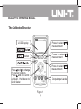
Model UT712: Users Manual
Table of Contents
Title
Introduction
Safety Information
The Calibrator Structure
LCD Display
Turning the Calibrator On
Measuring DC Volts (V and COM jack)
Sourcing DC Volts (V and COM jack)
Measuring DC mA (mA and COM jack)
Measuring DC mA with Loop Power (LOOP and mA jack)
Using the Current Output Modes
Sourcing mA
Simulating a Transmitter
Maintenance
In Case of Difficulty
Cleaning
Calibration
Replacing the Fuses
1
Page
3
4
7
8
9
9
10
11
12
13
13
15
16
16
16
16
17
Model UT712: OPERATING MANUAL
Title
Replacing the Battery
Specifications
DC Voltage and DC Current Input
DC Voltage and DC Current Output
General Specifications
Page
19
21
21
22
23
2
Model UT712: OPERATING MANUAL
Introduction
The Uni-Trend UT712 Volt/mA Calibrator is a source and measurement tool for 0 to
20mA current loop testing and DC Voltage from 0 to 20V. The calibrator does not
source and measure simultaneously.
Your calibrator has a unique design and large LCD can read the data clearly.
Your calibrator is supplied with the following:
User Manual
1 piece
Test Leads
1 set
Alligator Clip
1 set
Carrying Bag
1 piece
9V alkaline battery (ANSI/NEDA 1604A or IEC 6LR61)
1 piece
If the calibrator is damaged or something is missing, contact the place of purchase
immediately.
3
Model UT712: OPERATING MANUAL
International Symbols
Symbol
Meaning
Earth ground
Refer to this user manual for information about this feature.
Battery
Double insulated
Conforms to European Union directives.
Safety Information
Use the calibrator only as specified in this user manual, otherwise the protection
provided by the calibrator may be impaired.
A Warning identified conditions and actions that pose hazard(s) to her user.
4
Model UT712: OPERATING MANUAL
Warning
To avoid possible electric shock or personal injury:
Never apply more than 30V between any two jacks (terminals), or between
any jack and earth ground.
Make sure the battery door is closed before you operate the calibrator.
Remove test leads from the calibrator before you open the battery door.
Do not operate calibrator if it is damged.
Do not use or store the calibrator in an environment of high temperature,
humidity, explosive, inflammable and strong magnetic field. The performance
of the Meter may deteriorate after dampened.
When servicing the calibrator, use only specified replacement parts.
Use the proper jacks, function, and range for your measurementt or output
application.
To avoid false readings, which could lead to possible electric shock or
personal injury, replace the battery as soon as the battery indicator ( )
appears.
Turn the calibrator off when it is not in use and take out the battery when
not using for a long time.
5
Model UT712: OPERATING MANUAL
Constantly check the battery as it may leak when it has not been using for
some time, replace the battery as soon as leaking appears. A leaking
battery will damage the calibrator.
The internal circuit of the calibrator shall not be altered at will to avoid
damage of the calibrator and any acccident.
When the calibator is off, the jacks cannot connect to any loading or they
must not be short circuit between jacks.
When the calibrator is carrying out measurment, do not contact any bare
cable, connector, used jacks or the circuit under test.
6
Model UT712: OPERATING MANUAL
The Calibrator Structure
LCD Display
Press to select mA
measurement
INPUT Button
Press to select V
measurement
Press to select mV
measurement
Press and to change
the cursor location.
Press and to scroll
up/down. Hold down to
scroll faster.
Output/Input Jacks
Figure 1
7
Model UT712: OPERATING MANUAL
Figure 2
OUTPUT
INPUT
mV, V, mA
The calibrator is in output mode
The calibrator is in input mode
The measurement unit of the current reading
Battery is low. Replace the battery
The current cursor location
8
Model UT712: OPERATING MANUAL
Turning the Calibrator On
Press the yellow pushbutton to turn the calibrator on and off. Turn off the calibrator
when not in use.
Measuring DC Volts (V and COM jack)
2.Press so that INPUT
is on the display
INPUT
1.Press to turn the
calibrator on and off
mV or V depending on
range
3.Press to toggle mV
and V ranges
4.Insert the test leads
as shown
Figure 3
9
Model UT712: OPERATING MANUAL
Sourcing DC Volts (V and COM jack)
OUTPUT
The current cursor
location
2.Press so that
OUTPUT is on the
display
mV or V depending
on range
3.Press to toggle mV
and V ranges
1.Press to turn the
calibrator on and off
Press and to
change the cursor
location.
Press and to scroll
up/down. Hold down
to scroll faster.
4.Insert the test leads
as shown
Figure 4
10
Model UT712: OPERATING MANUAL
Measuring DC mA (mA and COM jack)
display “mA “
INPUT
2.Press so that INPUT
is on the display
3.Press to choose
mA range
1.Press to turn the
calibrator on and off
4.Insert the test leads
as shown
Figure 5
11
Model UT712: OPERATING MANUAL
Measuring DC mA with Loop Power (LOOP and mA jack)
display “mA “
INPUT
2.Press so that INPUT
is on the display
3.Press to choose
mA range
1.Press to turn the
calibrator on and off
4.Insert the test leads
as shown
Figure 6
12
Model UT712: OPERATING MANUAL
Using the Current Output Modes
In source mode, the calibrator supplies the current. In simulate mode, the calibrator
simulates a two-wire transmitter in an externally-powered current loop
Sourcing mA
Use source mode whenever you need to supply current into a passive circuit such
as a current loop with no loop supply. Insert the test leads into the OUTPUT + and
– mA jacks as shown on figure 7.
13
Model UT712: OPERATING MANUAL
OUTPUT
display “mA “
2.Press so that
OUTPUT is on the
display
The current cursor
location
3.Press to choose mA
1.Press to turn the
calibrator on and off
4.Insert the test leads
as shown
Press and to
change the cursor
location.
Press and to
scroll up/down. Hold
down to scroll faster.
Figure 7
14
Model UT712: OPERATING MANUAL
Simulating a Transmitter
Use simulate mode when an external 24 to 30V loop power supply is available.
Insert the test leads into the mA SIMULATE – and + jacks as shown below figure 8.
display “mA “
OUTPUT
The current
cursor location
2.Press so that
OUTPUT is on
the display
1.Press to turn
the calibrator on
and off
4.Insert the
test leads as
shown
Press and to
change the cursor
location.
Press and to
scroll up/down. Hold
down to scroll faster.
Figure 8
15
Model UT712: OPERATING MANUAL
Maintenance
Below provides basic maintenance information including battery and fuse replacement
instruction.
Warning
Do not attempt to repair or service your Meter unless you are qualified to
do so and have the relevant calibration, performance test, and service
information.
In Case of Difficulty
l Check the battery and test leads. Replace as necessary.
l Review this user manual to make sure you are using the correct jacks and
pushbuttons.
Cleaning
Periodically wipe the case with a damp cloth and detergent; do not user abrasives
or solvents.
Calibration
Calibrate your calibrator once a year to ensure that it performs according to its
specifications.
16
Model UT712: OPERATING MANUAL
Replacing the Fuses
Warning
To avoid electrical shock or arc blast, or personal injury or damage to the
Meter, use specified fuses ONLY in accordance with the following procedure.
Follow Figure 9 and proceed as follows to replace the Meter’s fuse:
l Turn the calibrator off and remove all connections from the terminals.
l Remove the screw from the battery compartment, and separate the battery
compartment from the case bottom.
l Remove the three screws from the case bottom, and separate the case bottom
from the case top.
l Remove the fuse by gently prying one end loose, then take out the fuse from
its bracket.
l Install ONLY replacement fuses with the identical type and specification as
follows and make sure the fuse is fixed firmly in the bracket.
17
Model UT712: OPERATING MANUAL
Fuse 1: 125mA, 250V, fast type fuse,
ø5×20mm
Fuse 2: 125mA, 250V, fast type fuse,
ø5×20mm
l Rejoin the case bottom and case top,
battery compartment and case bottom,
and install all the screws.
Figure 9
18
Model UT712: OPERATING MANUAL
Replacing the Battery
Warning
To avoid false readings, which could lead to possible electric shock or
personal injury, replace the battery as soon as the battery indicator ( )
appears.
Follow Figure 9 and proceed as follows to replace the battery.
l Turn the calibrator off and remove all the connections from the terminals.
l Remove the screw from the battery compartment, and separate the battery
compartment from the case bottom.
l Replace with a new 9V alkaline battery (ANSI/NEDA 1604A or IEC 6LR61)
l Rejoin the case bottom and the battery compartment, and reinstall the screw,
19
Model UT712: OPERATING MANUAL
Figure 10
20
Model UT712: OPERATING MANUAL
Specifications
Specifications are based on a one year calibration cycle and apply from +18
+28 unless stated otherwise.
to
DC Voltage and DC Current Input
Input
Range
DC Voltage
200mV
(0.00~200.00) mV
0.01mV
20V
(0.000~20.000) V
0.001V
20mA
(0.000~20.000) mA
0.001mA
Loop Current 20mA
(0.000~20.000) mA
0.001mA
DC Current
Input Range
Resolution
Input impedance: 1M (nominal).
When the input value is over the range, the LCD displays OL.
21
Accuracy
±(0.04%
readings +3
digits)
Model UT712: OPERATING MANUAL
DC Voltage and DC Current Output
Output
Range
DC Voltage 200mV
20V
DC Current 20mA
Simulate
20mA
Output Range
Resolution
(0.00~200.00) mV
0.01mV
(0.000~20.000) V
0.001V
(0.000~20.000) mA
0.001mA
(0.000~20.000) mA
0.001mA
Accuracy
±(0.04% readings
+3 digits)
mode
±10%
Loop Power 24V
l Voltage drive capability: 1mA.
l Source mode:
Compliance: 700 at 20mA for battery voltage >6.5V
l Simulate mode:
External loop voltage requirement: 24V nominal, 28V maximum, 12V minimum.
22
Model UT712: OPERATING MANUAL
General Specifications
l Resolution:
DC Voltage:0.01mV (200mV range), 0.001V (20V range)
DC Current:0.001mA (20mA Range)
l Maximum voltage applied between any jack and earth ground or between
any two jacks: 30V
l Storage temperature: -10 to 55
l Operating temperature: 0 to 50
l Operating altitude: 3000 meters maximum
l Temperature coefficient: ±0.005% of range per for the temperature ranges
0 to 18 and 28 to 50 .
l Relative humidity: 95% up to 30 , 75% up to 40 , 45% up to 50
l Vibration: Random 2g, 5 to 500Hz
l Shock: 1 meter drop test
l Safety:Complies with EN61326-1;2006,EN61326-2-2;2006
l Power requirements: Single 9V Alkaline battery (ANSI/NEDA 1604A or IEC
6LR61)
l Size: 193mm x 96mm x 47mm
l Weight: around 0.45kg with battery
23
Model UT712: OPERATING MANUAL
Copyright 2008 Uni-Trend Group Limited.
All rights reserved.
Manufacturer:
Uni-Trend Technology (Dongguan) Limited
Dong Fang Da Dao
Bei Shan Dong Fang Industrial Development District
Hu Men Town, Dongguan City
Guang Dong Province
China
Postal Code: 523 925
Headquarters:
Uni-Trend Group Limited
Rm901, 9/F, Nanyang Plaza
57 Hung To Road
Kwun Tong
Kowloon, Hong Kong
Tel: (852) 2950 9168
Fax: (852) 2950 9303
Email: [email protected]
http://www.uni-trend.com
24