1
Chapter 1
Operation
Introduction ................................................................................................... 1-4
The Command Processor ............................................................................... 1-4
Normal Mode and Security Mode ............................................................ 1-4
User Privilege Levels ................................................................................. 1-7
Remote Security Officer ........................................................................... 1-9
Entering Commands ................................................................................ 1-9
Aliases ................................................................................................... 1-10
Online Help ........................................................................................... 1-10
Storing and Retrieving Configuration Information .................................. 1-11
User Authentication Facility .......................................................................... 1-12
The User Authentication Database ......................................................... 1-13
Asynchronous Port Security ................................................................... 1-17
Telneting from the Router ...................................................................... 1-18
Counters ............................................................................................... 1-18
Semipermanent Manager Port ............................................................... 1-19
RADIUS ........................................................................................................ 1-19
TACACS ...................................................................................................... 1-21
Remote Management .................................................................................. 1-21
Monitoring and Fault Diagnosis ................................................................... 1-22
Event Logging ....................................................................................... 1-22
Restarts ................................................................................................. 1-22
CPU Utilisation ...................................................................................... 1-22
Memory ................................................................................................ 1-22
Power Supply ........................................................................................ 1-23
Nonvolatile Storage (NVS) ............................................................................ 1-24
FLASH Memory ............................................................................................ 1-24
Physical Characteristics .......................................................................... 1-25
The File Subsystem ....................................................................................... 1-25
File Naming Conventions ....................................................................... 1-25
Using Wildcards to Specify Groups of Files ............................................. 1-26
Working With Files ................................................................................ 1-27
FLASH File System ........................................................................................ 1-27
Working with FFS Files ........................................................................... 1-27
Compaction .......................................................................................... 1-28
FFS Messages ........................................................................................ 1-28
The Built-in Editor ........................................................................................ 1-28
HTTP Client and Server ................................................................................ 1-29
Resolving Uniform Resource Locators (URLs) .......................................... 1-31
Mail Subsystem ............................................................................................ 1-31
Configuration Examples ........................................................................ 1-32
Software Releases and Patches ..................................................................... 1-33
1-2
AR Series Router Reference Manual
Releases ................................................................................................ 1-33
Patches ................................................................................................. 1-35
Router Startup Operations ..................................................................... 1-35
Downloading Releases and Patches into the Router ............................... 1-37
Install Information ................................................................................. 1-38
Examples ............................................................................................... 1-39
Special Feature Licences ............................................................................... 1-42
Command Reference ................................................................................... 1-43
ACTIVATE FLASH COMPACTION ............................................................ 1-43
ADD ALIAS ............................................................................................ 1-44
ADD RADIUS SERVER ............................................................................ 1-45
ADD TACACS SERVER ........................................................................... 1-46
ADD USER ............................................................................................. 1-46
ADD USER RSO ..................................................................................... 1-48
CLEAR FLASH TOTALLY .......................................................................... 1-49
CREATE CONFIG .................................................................................... 1-49
CREATE FFILE ......................................................................................... 1-50
DELETE ALIAS ........................................................................................ 1-51
DELETE FFILE ......................................................................................... 1-52
DELETE FILE ........................................................................................... 1-52
DELETE INSTALL ..................................................................................... 1-53
DELETE MAIL ......................................................................................... 1-54
DELETE RADIUS SERVER ........................................................................ 1-54
DELETE TACACS SERVER ....................................................................... 1-55
DELETE USER ......................................................................................... 1-55
DELETE USER RSO ................................................................................. 1-56
DESTROY PATCH ................................................................................... 1-56
DISABLE FEATURE .................................................................................. 1-57
DISABLE HTTP DEBUG ........................................................................... 1-57
DISABLE HTTP SERVER ........................................................................... 1-58
DISABLE MAIL DEBUG ........................................................................... 1-58
DISABLE RELEASE .................................................................................. 1-59
DISABLE SYSTEM SECURITY_MODE ....................................................... 1-59
DISABLE USER ....................................................................................... 1-60
DISABLE USER RSO ................................................................................ 1-60
DUMP ................................................................................................... 1-61
EDIT ...................................................................................................... 1-62
ENABLE FEATURE .................................................................................. 1-65
ENABLE HTTP DEBUG ............................................................................ 1-65
ENABLE HTTP SERVER ............................................................................ 1-66
ENABLE MAIL DEBUG ............................................................................ 1-66
ENABLE RELEASE ................................................................................... 1-67
ENABLE SYSTEM SECURITY_MODE ....................................................... 1-68
ENABLE USER ........................................................................................ 1-68
ENABLE USER RSO ................................................................................. 1-69
HELP ..................................................................................................... 1-69
LOAD .................................................................................................... 1-70
LOGIN ................................................................................................... 1-73
LOGOFF ................................................................................................ 1-74
MAIL ..................................................................................................... 1-74
MODIFY ................................................................................................ 1-75
PURGE USER ......................................................................................... 1-76
RENAME ............................................................................................... 1-76
RESET HTTP SERVER .............................................................................. 1-77
RESET LOADER ...................................................................................... 1-77
RESET USER ........................................................................................... 1-78
RESTART ................................................................................................ 1-79
SET CONFIG .......................................................................................... 1-80
SET HELP ............................................................................................... 1-80
Software Release 2.0.1
C613-03018-00 REV A
Operation
1-3
SET HTTP SERVER .................................................................................. 1-81
SET INSTALL .......................................................................................... 1-82
SET LOADER .......................................................................................... 1-83
SET MAIL ............................................................................................... 1-85
SET MANAGER PORT ............................................................................. 1-86
SET NVS CLEAR_TOTALLY ...................................................................... 1-86
SET NVS CREATE ................................................................................... 1-87
SET NVS DELETE .................................................................................... 1-87
SET NVS MODIFY .................................................................................. 1-88
SET PASSWORD ..................................................................................... 1-89
SET SYSTEM CONTACT ......................................................................... 1-89
SET SYSTEM LOCATION ......................................................................... 1-90
SET SYSTEM NAME ............................................................................... 1-90
SET SYSTEM RPSMONITOR .................................................................... 1-91
SET SYSTEM TERRITORY ........................................................................ 1-91
SET TIME ............................................................................................... 1-92
SET USER ............................................................................................... 1-93
SHOW ALIAS ......................................................................................... 1-95
SHOW BUFFER ...................................................................................... 1-96
SHOW CONFIG ..................................................................................... 1-98
SHOW CPU ......................................................................................... 1-100
SHOW DEBUG ..................................................................................... 1-101
SHOW EXCEPTION .............................................................................. 1-103
SHOW FEATURE .................................................................................. 1-104
SHOW FFILE ........................................................................................ 1-105
SHOW FILE .......................................................................................... 1-107
SHOW FLASH ...................................................................................... 1-108
SHOW FLASH PHYSICAL ...................................................................... 1-109
SHOW HTTP CLIENT ............................................................................ 1-110
SHOW HTTP DEBUG ............................................................................ 1-111
SHOW HTTP SERVER ........................................................................... 1-112
SHOW HTTP SESSION .......................................................................... 1-113
SHOW INSTALL .................................................................................... 1-114
SHOW LOADER ................................................................................... 1-115
SHOW MAIL ........................................................................................ 1-116
SHOW MANAGER PORT ...................................................................... 1-118
SHOW NVS ......................................................................................... 1-118
SHOW NVS DUMP ............................................................................... 1-120
SHOW NVS FREE ................................................................................. 1-121
SHOW PATCH ..................................................................................... 1-122
SHOW RADIUS .................................................................................... 1-122
SHOW RELEASE ................................................................................... 1-123
SHOW STARTUP .................................................................................. 1-124
SHOW SYSTEM ................................................................................... 1-124
SHOW TACACS SERVER ...................................................................... 1-127
SHOW TIME ........................................................................................ 1-127
SHOW USER ........................................................................................ 1-128
SHOW USER RSO ................................................................................ 1-132
UPLOAD .............................................................................................. 1-134
Software Release 2.0.1
C613-03018-00 REV A
1-4
AR Series Router Reference Manual
Introduction
This section describes the functions and commands available on the router to
support day-to-day operational and network management activities.
The commands described in this section fall into six functional groups:
■
The command processor and router configuration.
■
The User Authentication Facility.
■
Monitoring and fault diagnosis of the router and the network.
■
Managing the nonvolatile storage (NVS).
■
Managing FLASH memory and the FLASH File System (FFS).
■
Downloading software releases and enhancements.
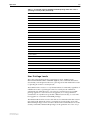
The Command Processor
The router is controlled and monitored with a set of commands which can be
entered from a terminal connected to one of the asynchronous ports, or by
using Telnet to connect to the router.
A user accessing the router from a terminal connected to an asynchronous port
in secure mode, or via a Telnet connection, must enter a login name and
password to gain access to the command prompt (see “User Authentication
Facility” on page 1-12).
The command processor supports three levels of privilege, USER, MANAGER,
and SECURITY OFFICER. USER and MANAGER privilege can be
distinguished by the prompt displayed by the command processor when it is
ready to receive commands. A USER level prompt looks like:
>
while a MANAGER prompt looks like:
Manager >
and a SECURITY OFFICER prompt looks like:
SecOff >
If the router’s system name has been defined with the command:
SET SYSTEM NAME=name
then the system name is included in the prompt. The MANAGER level prompt
for a router with the system name ho.noname.com looks like:
Manager ho.noname.com>
Normal Mode and Security Mode
The commands that a user may execute depend on the user’s privilege level
and the mode in which the router is operating. The router operates in one of
two modes, normal mode and security mode. By default the router operates in
normal mode. Security mode is designed to provide additional protection to
routers fitted with encryption hardware or configured to provide sensitive
Software Release 2.0.1
C613-03018-00 REV A
Operation
1-5
security functions such as IP authentication, Secure Shell (see Chapter 32, Secure
Shell), encryption (Chapter 15, Compression and Encryption Services) or IPsec
(Chapter 34, IP Security (IPsec)). Security mode is enabled using the command:
ENABLE SYSTEM SECURITY_MODE
which also creates a security mode enabler file in the router’s file subsystem.
This file can not be manually modified, displayed, deleted, copied or renamed.
If the router is restarted, the startup process checks for the presence of the
enabler file. If the enabler file is present the router boots up in security mode,
otherwise the router boots up in normal mode. The router is restored to normal
operating mode using the command:
DISABLE SYSTEM SECURITY_MODE
which also deletes the security mode enabler file in the router’s file subsystem.
Sensitive data files, such as encryption keys, can only be stored in the router’s
file subsystem when the router is operating in security mode.
When security mode is disabled, all sensitive data files are automatically
deleted.
The current operating mode is displayed using the command:
SHOW SYSTEM
When the router is operating in security mode, only users with SECURITY
OFFICER privilege (see “User Privilege Levels” on page 1-7) can execute
commands which could impact the security of the router and it’s keys
(Table 1-1 on page 1-5).
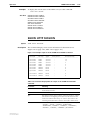
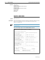
Table 1-1: Commands requiring SECURITY OFFICER privilege when the router is
operating in security mode.
Command
Specific Parameters
ACTIVATE IPSEC
ACTIVATE SCR
ADD FR DLC
ENCRYPTION
ADD IP INT
ADD IP SA
ADD SA
ADD SCR
ADD SSH
ADD USER
CLEAR NVS
CREATE CONFIG
CREATE ENCO KEY
CREATE FR
CREATE IPSEC
CREATE ISAKMP
CREATE PPP
CREATE PPP TEMPLATE
CREATE SA
Software Release 2.0.1
C613-03018-00 REV A
DEFENCRYPTION
1-6
AR Series Router Reference Manual
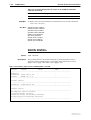
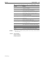
Table 1-1: Commands requiring SECURITY OFFICER privilege when the router is
operating in security mode. (Continued)
Command
Specific Parameters
CREATE SNMP COMMUNITY
CREATE STAR
DEACTIVATE SCR
DELETE FILE
DELELTE IP SA
DELETE NVS
DELETE SA
DELETE SCR
DELETE SSH
DELETE USER
DESTROY ENCO KEY
DESTROY IPSEC
DESTROY ISAKMP
DESTROY SA
DESTROY STAR
DISABLE FEATURE
DISABLE IPSEC
DISABLE ISAKMP
DISABLE SA
DISABLE SSH
DISABLE USER
DUMP
EDIT
ENABLE FEATURE
ENABLE IPSEC
ENABLE ISAKMP
ENABLE PPP DEBUG
ENABLE PPP TEMPLATE DEBUG
ENABLE SA
ENABLE SNMP
ENABLE SSH
ENABLE STAR
MKTTRANSFER
ENABLE USER
LOAD
MAIL
MODIFY
PURGE IPSEC
PURGE USER
RENAME FILE
RESET ENCO
Software Release 2.0.1
C613-03018-00 REV A
Operation
1-7
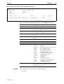
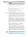
Table 1-1: Commands requiring SECURITY OFFICER privilege when the router is
operating in security mode. (Continued)
Command
Specific Parameters
RESET IPSEC
RESET USER
SET CONFIG
SET ENCO KEY
SET FR
ENCRYPTION, DEFENCRYPTION
SET INSTALL
SET IP INT
SET IPSEC
SET PPP
SET PPP TEMPLATE
SET SA
SET SCR
SET SNMP COMMUNITY
SET SSH
SET STAR
SET USER
SHOW CONFIG
SHOW ENCO KEY
SHOW FEATURE
SHOW FILE
SHOW NVS
SHOW PPP
CONFIG
SHOW STAR
[=id], MKTTRANSFER, NETKEY
UPLOAD
User Privilege Levels
The router supports three levels of privilege for users: USER (lowest),
MANAGER and SECURITY OFFICER (highest). The commands that can be
executed by a user depend on the user’s privilege level and whether the router
is operating in normal or security mode:
The USER level has access to a very limited subset of commands, regardless of
whether the router is operating in normal or security mode. USER level
commands only affect the user’s own session or asynchronous port. USER
privilege applies to a user who has not logged in (i.e. is using a terminal
connected to an asynchronous port that is not in secure mode), or a user who
has logged in to a username with USER privilege.
The MANAGER level has access to the full set of commands when the router is
in normal mode. When the router is operating in security mode, users with
MANAGER privilege can not execute a subset of the commands known as the
security commands. MANAGER privilege can be gained in one of two ways:
Software Release 2.0.1
C613-03018-00 REV A
1-8
AR Series Router Reference Manual
■
Using the command:
LOGIN
from any port or Telnet session to login under a login name that has
MANAGER privilege. The command prompts for a login name and
password. The password is case-sensitive and must be entered exactly as
defined. If the password is entered correctly, the port or Telnet connection
gains MANAGER privilege and the prompt changes to the MANAGER
level prompt. This is the usual method of gaining MANAGER privilege,
especially when managing remote routers.
■
Using the command:
SET MANAGER PORT
to set a particular port as a semipermanent MANAGER port. Any terminal
connected to the specified port will have MANAGER privilege. The SET
MANAGER PORT command on page 1-86 is a MANAGER level command
and can only be entered from a port or a Telnet session that already has
MANAGER privilege. Only one port at a time can be defined as manager
port.
To return to USER mode, use the command:
LOGOFF
Normally, the prompt changes when the user’s privilege level changes from USER to
MANAGER or vice versa. The prompt will not change if commands are being entered
from a terminal connected to a physical port and the port’s PROMPT parameter has
been changed to a user-defined string with the SET PORT command on page 2-32 of
Chapter 2, Interfaces.
The SECURITY OFFICER level has access to the full set of commands
regardless of whether the router is operating in normal mode or security mode.
When the router is operating in security mode, only users with SECURITY
OFFICER privilege can execute security commands (see Table 1-1 on page 1-5).
When the router is operating in normal mode MANAGER privilege is
equivalent to SECURITY OFFICER privilege. A user can only log in under a
login name that has SECURITY OFFICER privilege from either a terminal
directly connected to an asynchronous port on the router or a Telnet session
originating from an authorised IP address (see “Remote Security Officer” on
page 1-9).
A security timer operates while a user is logged in with SECURITY OFFICER
privilege, to minimise the risk of unauthorised access to an un-attended
terminal or Telnet session. Every time a security command is entered, the
security timer is restarted. If the timer expires the user’s privilege is reset to
MANAGER level, but the user remains logged in. Any attempt to execute a
security command will require the user to re-enter the SECURITY OFFICER
password. The timeout period, in seconds, can be configured using the
command:
SET USER SECUREDELAY=10..600
Software Release 2.0.1
C613-03018-00 REV A
Operation
1-9
Remote Security Officer
The Remote Security Officer (RSO) feature enables a remote user to connect to a
router via Telnet from an authorised IP address, and login using a login name
with SECURITY OFFICER privilege as if the user were at a terminal connected
directly to the router. By default the Remote Security Officer feature is disabled.
The RSO feature can be enabled or disabled using the commands:
ENABLE USER RSO
DISABLE USER RSO
Authorised IP addresses can added or deleted with the command:
ADD USER RSO IP=ipadd [MASK=ipadd]
DELETE USER RSO IP=ipadd
The MASK parameter allows a range of IP addresses to be added. The current
state of the RSO feature and the list of authorised IP addresses can be displayed
using the command:
SHOW USER RSO
All RSO commands require SECURITY OFFICER privilege and therefore must
be executed from a terminal directly attached to the router or from a Telnet
session originating from a previously configured RSO address. RSO must be
enabled, and the first address added, from a terminal directly attached to the
router. If RSO is disabled (either from a terminal or a Telnet session) it can only
be re-enabled from a terminal directly attached to the router.
Once RSO has been enabled and configured with one or more IP addresses, a
Telnet session from one of the authorised addresses will be able to login as a
user with SECURITY OFFICER privilege.
Entering Commands
The router supports command line editing and recall. The functions available
are:
■
Move the cursor backwards and forwards in the command line, using the
cursor keys.
■
Move the cursor to either end of the command line with a single keystroke.
■
Insert and delete characters.
■
Clear the command line.
■
Toggle between insert and overstrike editing modes.
■
Recall, edit and execute previous commands.
■
Move backwards and forwards through a history of previous commands.
■
Display a command history and select a command from the list.
■
Clear the command history.
■
Recall the most recent command matching a partially entered command.
Table 1-2 on page 1-10 lists the functions and the terminal keys or key
combinations used to access these functions.
Software Release 2.0.1
C613-03018-00 REV A
1-10
AR Series Router Reference Manual
Table 1-2: Command line editing functions and keystrokes.
Function
VT100 Terminal
Dumb terminal
Move cursor within command line ←, →
Not available
Delete character to left of cursor
[Delete] or [Backspace]
[Delete] or [Backspace]
Toggle between insert/overstrike
[Ctrl/O]
Not available
Clear command line
[Ctrl/U]
[Ctrl/U]
Recall previous command
↑ or [Ctrl/B]
[Ctrl/B]
Recall next command
↓ or [Ctrl/F]
[Ctrl/F]
Display command history
[Ctrl/C] or
SHOW PORT HISTORY
[Ctrl/C]
or SHOW PORT HISTORY
Clear command history
RESET PORT HISTORY
RESET PORT HISTORY
Recall matching command
[Tab] or [Ctrl/I]
[Tab] or [Ctrl/I]
The router assumes that the width of the terminal screen is 80 characters, and
performs command line wrapping at the 80th column regardless of the setting
of the terminal. The cursor does not need to be at the end of the line for the
command to be executed. The default editing mode is insert mode. Characters
are inserted at the cursor position and any characters to the right of the cursor
are pushed to the right to make room. In overstrike mode, characters are
inserted at the cursor position and replace any existing characters.
Aliases
The command line interface supports aliases. An alias is a short name for an
often-used longer character sequence. When the user presses [Enter] to execute
the command line, the command processor first checks the command line for
aliases and substitutes the replacement text. The command line is then parsed
and processed normally. Alias substitution is not recursive—the command line
is scanned only once for aliases.
Aliases are created and destroyed using the commands:
ADD ALIAS=name STRING=substitution
DELETE ALIAS=name
A list of all the aliases defined on the router and their replacement strings can
be displayed using the command:
SHOW ALIAS
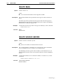
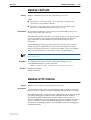
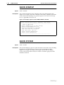
Online Help
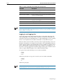
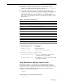
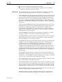
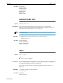
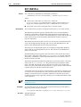
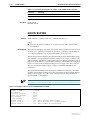
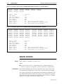
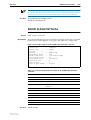
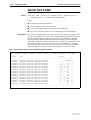
Online help is available for all router commands. Typing a question mark “?” at
the end of a partially completed command displays a list of the parameters that
may follow the current command line, with the minimum abbreviations in
uppercase letters (Figure 1-1 on page 1-11). The current command line is then
re-displayed, ready for further input.
Software Release 2.0.1
C613-03018-00 REV A
Operation
1-11
Figure 1-1: Using the question mark character (“?”) to display help for the current command.
Manager > ADD ?
Options : ACC APPletalk BOOTp BRIDge DECnet FRamerelay GRE IP IPX ISDN
LAPD LOG MIOX NTP OSPF PERM PPP RADius SA SCript SNmp STReam STT TRGger
TACacs USEr X25C X25T TDM
Manager > ADD ACC ?
Options : CALL SCript DOmainname
Manager > ADD ACC CALL ?
Options : DIrection DScript CScript RScript POrt ENcapsulation AUthentication
DOmainname
A multilingual, language-independent online help facility provides more
detailed help information via the command:
HELP [topic]
If a topic is not specified, a list of available topics is displayed. The HELP
command on page 1-69 displays information from the system help file stored
in either NVS or FLASH memory. The help file uses a simple mark-up
language to identify topics, access level (USER or MANAGER) and help text.
Both standard ASCII and Unicode character encodings are supported.
Alternate help files can be uploaded and stored in either NVS or FLASH, then
activated using the command:
SET HELP=helpfile
The current help file can be displayed with the command:
SHOW SYSTEM
The help file is easily modified, for example to provide detailed site-specific
support information. The mark-up language specification and preprocessor
program are available from your distributor or reseller.
Storing and Retrieving Configuration Information
At boot the router executes the commands in the boot script to configure the
router. The default boot script is called boot.cfg, but an alternative script file
can be defined as the boot script using the command:
SET CONFIG=filename
Subsequent commands entered from the command line or executed from a
script affect only the dynamic configuration in memory, which is not retained
over a power cycle. Changes are not automatically stored in nonvolatile
memory. When the router is restarted the configuration will be restored to that
defined by the boot script, or if the router was restarted using the RESTART
command on page 1-79, any script specified in the RESTART command.
To ensure that any configuration changes made after boot are retained across a
restart or power cycle, the modified configuration must be saved as a script
file, using the command:
CREATE CONFIG=filename
Software Release 2.0.1
C613-03018-00 REV A
1-12
AR Series Router Reference Manual
The CREATE CONFIG command on page 1-49 writes the MD5 digest, not the
cleartext, of passwords in commands to the configuration file. When a configuration
script is executed the command processor can determine whether the password value is
cleartext or an MD5 digest.
If the file name specified is boot.cfg, or the file is set as the boot script using
the SET CONFIG command on page 1-80, the modified configuration will
automatically be restored after a restart or power cycle. If another name is
specified, the configuration can be restored after a restart or power cycle using
the command:
ACTIVATE SCRIPT=filename
User Authentication Facility
The User Authentication Facility (UAF) controls access to the router’s command
prompt, asynchronous services and dialup services via a login name and
password. A user will be prompted to enter a login name and password when:
■
The user attempts to access the router’s command prompt via a terminal
connected directly to an asynchronous port set to SECURE mode.
■
The user attempts to access the router’s command prompt via a Telnet
connection.
■
The user attempts to access a dialup service via an asynchronous modem
connected to an asynchronous port.
■
The user enters the LOGIN command on page 1-73.
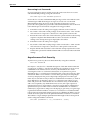
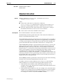
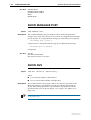
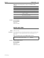
The UAF prompts the user for a login name and password (Figure 1-2 on
page 1-12). The user must enter appropriate responses, pressing [Return] after
each response. Characters entered at the password prompt are not echoed to
the screen, for security reasons.
Figure 1-2: A typical login session for user BRUCE on router CMD.
CMD login: bruce
password:
CMD >
If the user enters an invalid login name or password, the sequence is repeated a
set number of times. If a valid login name and password has still not been
entered the terminal or Telnet session is locked out for a period of time. During
this period the password prompt is withheld, preventing the user from logging
in or entering commands. The manager can specify the number of login
attempts allowed and the length of the lockout period.
The password prompt is displayed regardless of whether or not a password is required
for the login name entered by the user. This makes it more difficult for an intruder to
discover valid login name/password combinations.
Software Release 2.0.1
C613-03018-00 REV A
Operation
1-13
The users authenticated by the UAF can be operators or other routers. If the
user is another router, the authentication will occur without appearing in a
terminal screen.
The UAF supports three methods of user authentication, an internal database
called the User Authentication Database, and interrogation of external RADIUS
(Remote Authentication Dial In User Service) or TACACS (Terminal Access
Controller Access System) servers.
The UAF first queries the User Authentication Database. If the supplied login
name and password does not match an entry in the User Authentication
Database, the UAF sends authentication requests to any RADIUS servers that
have been defined. If there are no defined RADIUS servers or all the RADIUS
servers return a reject response, the UAF will send authentication requests to
any TACACS servers that have been defined. If the supplied login name and
password matches an entry in the User Authentication Database, or one of the
defined RADIUS or TACACS servers returns an accept response to an
authentication request, the login is accepted. If the supplied login name and
password does not match an entry in the User Authentication Database, and all
of the defined RADIUS or TACACS servers return reject responses to
authentication requests, the login is rejected.
The User Authentication Database
The User Authentication Database stores information about the users who are
permitted to have access to the router’s command prompt, asynchronous
services and dialup services. Users are identified by a login name. Each login
name has an associated record in the database which specifies:
■
The password that the user must enter to login to the router.
■
The privilege level for the user: USER, MANAGER or SECURITY
OFFICER.
■
Whether or not the user is permitted to use the TELNET command on
page 11-24 of Chapter 11, Terminal Server, or to connect to a Telnet service
from a Telnet session.
■
The IP address, network mask and MTU (Maximum Transmission Unit) to
use for PPP or SLIP connections to the router via an asynchronous port.
■
A callback number for use with the PPP callback facility.
Adding Entries to the User Authentication Database
When the router is started up for the first time one account is created
automatically. This account has the login name MANAGER, the password
“friend”, and MANAGER privilege. This account can not be deleted, although
the password may be changed. The MANAGER account makes the MANAGE
command (supported in Release 6.6 and earlier) obsolete.
The manager should change the password of the MANAGER account at the
earliest opportunity. Leaving the MANAGER account with the default
password is a security risk, as the account name and default password are well
documented.
Software Release 2.0.1
C613-03018-00 REV A
1-14
AR Series Router Reference Manual
Additional users can be added to the User Authentication Database using the
command:
ADD USER=login-name PASSWORD=password [CALLINGNUMBER=number]
[CBNUMBER=e164number] [DESCRIPTION=description]
[PRIVILEGE={USER|MANAGER|SECURITYOFFICER}] [TELNET={YES|
NO}] [IPADDRESS=ipadd] [IPXNETWORK=network]
[NETMASK=ipadd] [MTU=40..1500]
The number of entries in the database is limited only by the amount of memory
available. Only the login name and password must be specified. The default
privilege level is USER. Other information about a user that may be specified
includes a description for the entry (e.g. the user’s full name), the privilege
level, whether or not the user is permitted to use the TELNET command on
page 11-24 of Chapter 11, Terminal Server or connect to a Telnet service, an IP
number, network mask and MTU (Maximum Transmission Unit). The IP
number, network mask and MTU are only required if the user is to run
asynchronous PPP or SLIP over an asynchronous modem connected to an
asynchronous port. The callback number is only required if the user is to make
a PPP callback request with user authentication. See Chapter 3, Point-to-Point
Protocol (PPP) for more information. The calling number is only used for L2TP
and ISDN services that provide caller ID information.
Modifying Entries in the User Authentication Database
An entry in the database can be modified with the command:
SET USER=login-name [PASSWORD=password]
[CALLINGNUMBER=number] [CBNUMBER=e164number]
[DESCRIPTION=description] [PRIVILEGE={USER|MANAGER|
SECURITYOFFICER}] [TELNET={YES|NO}] [IPADDRESS=ipadd]
[IPXNETWORK=network] [NETMASK=ipadd] [MTU=40..1500]
An entry in the database can be deleted using the command:
DELETE USER=login-name
All entries in the database, except the MANAGER account, can be deleted with
the command:
PURGE USER
The contents of the database can be displayed with the command:
SHOW USER[=login-name]
Passwords
All users, including managers, should take care in selecting passwords. Tools
exist that enable hackers to guess or test many combinations of login names
and passwords easily. The UAF provides some protection against such attacks
by allowing the manager to set the number of consecutive login failures
allowed and a lockout period when the limit is exceeded.
However, the best protection against password discovery is to select a good
password, and keep it secret. When choosing a password:
■
Do make it six or more characters in length. The UAF enforces a minimum
password length, which can be changed by the manager. The default is six
characters.
■
Do include both alphabetic (a–z) and numeric (0–9) characters.
Software Release 2.0.1
C613-03018-00 REV A
Operation
1-15
■
Do include both uppercase and lowercase characters. The passwords
stored by the router are case-sensitive, so “bgz4kal” and “Bgz4Kal” are
different.
■
Do avoid words found in a dictionary, unless combined with other random
alphabetic and numeric characters.
■
Do not use the login name, or the word “password” as the password.
■
Do not use your name, your mothers name, your spouses name, your pets
name, or the name of your favourite cologne, actor, food or song.
■
Do not use your birth date, street number or telephone number.
■
Do not write down your password anywhere.
A manager can alter the password for any user with the command:
SET USER=username PASSWORD=password
This may be necessary if the user has forgotten the password. A log message is
generated whenever the password for a manager account is changed.
A user who is logged in can change their own password using the command:
SET PASSWORD
which prompts for the old password, the new password and confirmation of
the new password. The new password and the confirmation must be identical
for the change to take affect. This reduces the chances of a typing error causing
the password to be different from what the user intended.
Database Security
A manager session that is left unattended is a severe security risk. In particular,
the User Authentication Database can be modified from a manager session. To
reduce the risk of unauthorised activity, a subset of manager commands
(Table 1-3 on page 1-16), called the security commands, have a security timer.
When one of the security commands is entered from a manager session, the
security timer is started. Each time a security command is entered the timer is
restarted. If a security command is entered after the timer has expired, the
manager is prompted to re-enter the password correctly before the command
will be actioned. If the password is not entered correctly the password prompt
will be repeated a set number of times, and if the correct password is still not
entered a log message is generated and the session is logged off.
The security timer enables a manager to make successive additions and
modifications to the database at one time without having to re-enter the
password for every command.
The security timer does not provide a foolproof security mechanism. Managers
should always attempt to log out of a manager session before leaving a
terminal unattended.
Software Release 2.0.1
C613-03018-00 REV A
1-16
AR Series Router Reference Manual
Table 1-3: Secure commands controlled by the security timer.
Command
Description
ADD TACACS SERVER
Adds a TACACS server to the list of TACACS servers used
for user authentication.
ADD USER
Adds a user to the User Authentication Database.
DELETE TACACS SERVER
Deletes a TACACS server from the list of TACACS servers
used for user authentication.
DELETE USER
Deletes a user from the User Authentication Database.
PURGE USER
Deletes all users except MANAGER from the User
Authentication Database.
SET MANAGER PORT
Assigns a port semipermanent MANAGER privilege.
SET USER
Modifies a user record in the User Authentication Database.
If the router is operating in security mode, the manager must also be logged in to a user
account with SECURITY OFFICER privilege in order to execute any of the commands
listed in Table 1-3 on page 1-16.
Logging In and Logging Out
A user will automatically be prompted to enter a login name and password
when attempting to access the router via Telnet or a terminal connected to an
asynchronous port set to SECURE mode, or when attempting to access a dialup
service via an asynchronous modem connected to an asynchronous port.
There are other occasions when a user may wish to login manually. A user on a
terminal connected to an asynchronous port that is not in SECURE mode may
wish to login in order to use facilities that are only available to logged in users,
such as the TELNET command on page 11-24 of Chapter 11, Terminal Server. A
user who is already logged in may wish to temporarily login as another user in
order to acquire different rights, such as MANAGER privilege.
To log in to the router manually, use one of the commands:
LOGIN
LOGON
LOGI
which are synonyms. To log out of a session, use one of the commands:
LOGOFF
LOGOUT
LO
which are synonyms.
If a user Telnets to the router but does not attempt to login within one minute, the router
automatically times out the session and terminates the Telnet connection.
Software Release 2.0.1
C613-03018-00 REV A
Operation
1-17
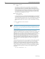
Recovering Lost Passwords
If a user forgets their password, the password can be reset from an account
with MANAGER privilege, using the command:
SET USER=login-name PASSWORD=password
Passwords for accounts with MANAGER privilege can be reset with the same
command, provided the manager can login to at least one account with
MANAGER privilege. However, in the event that all manager account
passwords are forgotten, the password for the MANAGER account can be reset
to the default password “friend” using the following procedure:
1.
Switch the router off at the power supply and remove the router lid.
2.
Set switch 3 of the DIP switch package on the CPU board to “ON”. See the
relevant section of Appendix A, Hardware for the specific router model.
3.
Restart the router. The router will not become operational but as the startup
sequence completes the MANAGER account is restored to its default
settings and a startup message is displayed to this effect.
4.
Switch the router off at the power supply.
5.
Set switch 3 of the DIP switch package on the CPU board to “OFF”. See the
relevant section of Appendix A, Hardware for the specific router model.
6.
Replace the lid and restart the router. After the startup sequence the router
will become operational with the MANAGER account restored to its default
settings.
Asynchronous Port Security
Asynchronous ports may be set to SECURE mode, using the command:
SET PORT SECURE=ON
See Chapter 2, Interfaces for a detailed description of the SET PORT command
on page 2-32 of Chapter 2, Interfaces. By default, all asynchronous ports are set
to SECURE mode. Telnet sessions are always in SECURE mode. A user
accessing the router via a terminal connected to an asynchronous port in
SECURE mode, or via Telnet, must login before the router will accept any other
commands. When a user Telnets to a router the login and password prompts
are always displayed. The password prompt is displayed even if the login
name does not match an entry in the User Authentication Database, to make it
more difficult for an intruder to discover a valid login name. When a login
name and password is entered that does not match an entry in the database,
and is not accepted by any defined TACACS servers, the login sequence is
repeated. If successive login failures occur, the login prompt is withheld for a
specified lockout period. This makes it much more difficult for an intruder to
randomly try login names and passwords hoping to gain entry. A log message
is generated when the number of retries for a connection is exceeded and the
lockout period is instigated. Telnet logins from an offending IP address are also
locked out for this period once the permitted number of failures is exceeded.
The number of login attempts permitted and the length of the lockout period
can be configured with the command:
SET USER [LOGINFAIL=1..10] [LOCKOUTPD=0..30000]
Software Release 2.0.1
C613-03018-00 REV A
1-18
AR Series Router Reference Manual
Telneting from the Router
The router provides three modes of access to host services:
■
Using the CONNECT command on page 11-13 of Chapter 11, Terminal
Server to access asynchronous services. These are typically hosts connected
directly to asynchronous ports on the router and defined as services using
the SET SERVICE command on page 11-17 of Chapter 11, Terminal Server.
■
Using the CONNECT command on page 11-13 of Chapter 11, Terminal
Server to access Telnet services. These are typically Telnet hosts defined as
services using the SET SERVICE command on page 11-17 of Chapter 11,
Terminal Server.
■
Using the TELNET command on page 11-24 of Chapter 11, Terminal Server to
access Telnet hosts.
Each entry in the database has a TELNET attribute, which determines which
modes of access the user is permitted to use.
All users can use the CONNECT command on page 11-13 of Chapter 11,
Terminal Server to access asynchronous services, although users accessing the
router via Telnet or a terminal attached to an asynchronous port in SECURE
mode must login first to gain access to the command prompt.
Users logged into the router via a terminal attached to an asynchronous port
can also use the CONNECT command on page 11-13 of Chapter 11, Terminal
Server to access Telnet services. In addition, if the user is logged in to an
account with the TELNET attribute set to “ON” the user can use the TELNET
command on page 11-24 of Chapter 11, Terminal Server to Telnet to remote hosts.
Users logged into the router via Telnet can, by default, only use the CONNECT
command on page 11-13 of Chapter 11, Terminal Server to access asynchronous
services. If the user is logged in to an account with the TELNET attribute set to
“ON” the user can also use the CONNECT command on page 11-13 of Chapter
11, Terminal Server to access Telnet services and the TELNET command on
page 11-24 of Chapter 11, Terminal Server to Telnet to remote hosts.
A manager can use the TELNET attribute to allow users connected to the
router via a terminal to access a restricted set of Telnet hosts, by defining those
hosts as Telnet services (see the description of the SET SERVICE command on
page 11-17 of Chapter 11, Terminal Server and setting the TELNET attribute to
“OFF” for selected accounts. Users logged in to one of these accounts can use
the CONNECT command on page 11-13 of Chapter 11, Terminal Server to access
the Telnet services but can not use the TELNET command on page 11-24 of
Chapter 11, Terminal Server to access any other Telnet hosts.
Counters
A number of counters record activity associated with the User Authentication
Database. Counters relating to specific users in the database can be displayed
with the command:
SHOW USER[=login-name]
Global counters and configuration parameters can be displayed with the
command:
SHOW USER CONFIGURATION
Software Release 2.0.1
C613-03018-00 REV A
Operation
1-19
All counters are stored in nonvolatile storage so that they are retained across
router reboots and power cycles.
The counters for a specific user can be reset to zero using the command:
RESET USER=login-name
The counters for all users, the global counters, or all counters can be reset to
zero with the command:
RESET USER COUNTER={USER|GLOBAL|ALL}
Semipermanent Manager Port
It is sometimes desirable to have an asynchronous port that has MANAGER
privilege after a router reboot, without a manager having to log on. An
asynchronous port can be set to default to MANAGER privilege using the
command:
SET MANAGER PORT=port-number
Only one port may be a semipermanent manager port. By default, no
semipermanent manager port is defined. This command is defined as one of
the security commands (see “Database Security” on page 1-15).
When the router boots with a semipermanent manager port configured, the
MANAGER account is automatically logged in to the port. The port has full
MANAGER privilege and there is no restriction on Telneting from the port.
The security timer is reset so that the first time a security command is entered
the user will be challenged for the password for the MANAGER account.
RADIUS
RADIUS (Remote Authentication Dial In User Service) is a protocol for
transferring authentication, configuration and accounting information between
a Network Access Server (e.g. a router) which desires to authenticate its links,
and a shared RADIUS Server. The RADIUS (authentication) server manages a
database of users and provides authentication (verifying user name and
password) and configuration information (e.g. IP address, subnet mask, etc.) to
the client. The RADIUS (accounting) server stores accounting information
about past sessions.
The router acts as a RADIUS client, sending requests to a defined list of
RADIUS servers. Router modules use RADIUS in different ways depending on
their individual requirements. See the relevant chapter for specific details of
how RADIUS is used by the router. For example, ISDN and ACC can be
configured to use RADIUS to authenticate a call and return information such as
the IP address and network mask to be used to complete the call.
A RADIUS server is added or deleted using the commands:
ADD RADIUS SERVER=ipadd SECRET=secret
DELETE RADIUS SERVER=ipadd
The list of known RADIUS servers is displayed using the command:
SHOW RADIUS
Software Release 2.0.1
C613-03018-00 REV A
1-20
AR Series Router Reference Manual
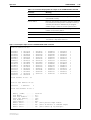
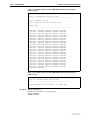
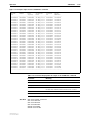
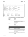
Table 1-4 on page 1-20 lists the RADIUS attributes supported by the router.
Table 1-4: RADIUS attributes supported by the router.
RADIUS Attribute Name
When Used
Description
User-Name
Authentication request
Accounting request
The name of the user to be authenticated.
User-Password
Authentication request
The password of the user to be authenticated, or the user’s
input following an Access-Challenge.
CHAP-Password
Authentication request
The response value provided by a PPP CHAP user in
response to a challenge.
NAS-IP-Address
Authentication request
Accounting request
The identifying IP Address of the NAS which is requesting
authentication of the user.
NAS-PORT
Authentication request
The physical port number of the NAS which is
authenticating the user.
Calling-Station-Id
Authentication request
The number that the call to the NAS came from, using
Automatic Number Identification (ANI) or similar
technology.
Framed-IP-Address
Authentication accept
The address to be configured for the user.
Framed-IP-Netmask
Authentication accept
The IP Netmask to be configured for the user when the user
is a router to a network.
Callback-Number
Authentication accept
A dialling string to be used for callback.
Framed-Route
Authentication accept
Provides routing information to be configured for the user
on the NAS.
Framed-IPX-Network
Authentication accept
The IPX Network number to be configured for the user.
Session-Timeout
Authentication accept
The maximum number of seconds of service to be provided
to the user before the session terminates.
Idle-Timeout
Authentication accept
The maximum number of consecutive seconds of idle
connection allowed to the user before prompt or
termination of the session.
Framed-AppleTalk-Network
Authentication accept
The AppleTalk Network number which the NAS should
probe to allocate an AppleTalk node for the user.
Framed-AppleTalk-Zone
Authentication accept
The AppleTalk Default Zone to be used for this user.
CHAP-Challenge
Authentication request
The CHAP Challenge sent by NAS to a PPP CHAP user.
Acct-Status-Type
Authentication start
Whether or not the Accounting Request marks the
beginning (Start) or end (Stop) of the user service.
Acct-Input-Octets
Authentication stop
The number of octets received from the port over the
course of this service.
Acct-Output-Octets
Accounting stop
The number of octets sent to the port over the course of this
service.
Acct-Session-Id
Accounting start
Accounting stop
A unique accounting ID used to match start and stop
records in a log file.
Acct-Authentic
Accounting start
The method by which the user was authenticated.
Acct-Input-Packets
Accounting stop
The number of packets received from the port in the course
of delivering this service to a Framed User.
Acct-Output-Packets
Accounting stop
The number of packets sent to the port in the course of
delivering this service to a Framed User.
Acct-Terminate-Cause
Accounting stop
The mechanism or reason for terminating the session.
Software Release 2.0.1
C613-03018-00 REV A
Operation
1-21
TACACS
The router supports the use of TACACS (Terminal Access Controller Access
System) servers as an alternative method of user authentication. The router
sends a TACACS request, which includes the username and password, to each
TACACS server in turn. The TACACS server responds with an “accept” or
“reject” response. If the response is “accept” then the user is authenticated. If the
response is “reject”, a request is sent to the next server in the list until all servers
have been queried. If all the servers on the list reject the request then the user
authentication is rejected.
There is a timeout period for TACACS requests, and if a response is not
received within the specified time, the request is retried. The timeout period
and the number of retries to be attempted can be configured using the
command:
SET USER [TACRETRIES=0..10] [TACTIMEOUT=1..60]
Requests are sent to the TACACS servers on the list in a round-robin fashion
until one of the servers accepts the request, all of the servers have rejected the
request or the number of retries has been reached for each server.
A TACACS server is added to the list of defined servers with the command:
ADD TACACS SERVER=ipadd
where ipadd is the IP address of the TACACS server, in dotted decimal notation.
A TACACS server can be deleted from the list of servers using the command:
DELETE TACACS SERVER=ipadd
The list of currently defined TACACS servers can be displayed with the
command:
SHOW TACACS SERVER
Remote Management
Managing remote routers is as easy as managing the local router to which the
terminal is connected. From a terminal connected to any port (with either
USER or MANAGER privilege), use the command:
TELNET ipadd
to Telnet to the remote router, specifying the remote router’s IP address. If the
connection is successful a login prompt from the remote router is displayed.
Login using a login name that has been defined with MANAGER privilege
(such as the default MANAGER login name), and enter the password.
To return to the local router, use the command:
LOGOFF
to terminate the connection. For more information about using Telnet, see
Chapter 11, Terminal Server.
Software Release 2.0.1
C613-03018-00 REV A
1-22
AR Series Router Reference Manual
Monitoring and Fault Diagnosis
Event Logging
The router responds to certain significant events by generating an event log
message. Each router maintains a local event log of the most recent log
messages. To view the log, use the command:
SHOW LOG
The logging facility provides a powerful, flexible and easily configurable tool
for monitoring network activity and selecting and displaying the results. Userdefined output definitions can filter, prioritise and output log messages to
RAM, NVS, an asynchronous port, another router, a syslog server or an email
address. See Chapter 23, Logging Facility for a detailed description of the logging
facility.
Restarts
Some changes to configuration parameters require the router to be restarted for
the changes to take affect. The router is restarted with the command:
RESTART {REBOOT|ROUTER} [CONFIG={filename|NONE}]
If the router encounters a fatal error condition from which it can not recover, it
automatically performs a restart. The reason for the restart may be determined
by examining the router’s exception list, with the command:
SHOW EXCEPTION
The conditions that the router encountered when it last restarted, such as the
amount of RAM and the state of the battery-backed RAM, can be viewed with
the command:
SHOW STARTUP
A complete snapshot of the state of the router prior to the last fatal condition
can be displayed with the command:
SHOW DEBUG
CPU Utilisation
The CPU utilisation over the last second, ten seconds, one minute or since the
router last restarted can be displayed with the command:
SHOW CPU
Memory
The state of the router’s buffer pool can be examined with the command:
SHOW BUFFER
If the pool of free buffers drops below a critical threshold, the router
progressively disables processes, resulting in a loss of functionality. This
problem can potentially arise when a fast source sends enormous amounts of
data to a slow destination or down a slow link. However, the cause is more
Software Release 2.0.1
C613-03018-00 REV A
Operation
1-23
likely to be a problem with the router itself. The problem can be corrected in
the short term by restarting the router, but it should be reported to your
supplier.
Fast buffer memory, on power PC based routers and switches only) is cached
by the CPU and is available only for program variable storage. It cannot be
used for packet buffers.
The contents of memory can be examined with the command:
DUMP
and modified with the command:
MODIFY
The DUMP command on page 1-61 and the MODIFY command on page 1-75 are
provided as diagnostic tools and should not be needed for normal operation of
the router. Inappropriate use of these commands may cause a malfunction of the
router, resulting in the loss of network services.
Power Supply
The AT-AR740 router automatically monitors its own power supply and fan,
and has the option of a redundant power supply. If a redundant power supply
(RPS) is attached, the AT-AR740 software can detect the presence of the RPS
and the state of its output voltages and fan. RPS monitoring, turned off by
default, can be turned on or off using the command:
SET SYSTEM RPSMONITOR={ON|OFF}
The SHOW SYSTEM command on page 1-124 displays the state of the main
power supply and fan, and whether or not the RPS is being monitored. If RPS
monitoring is enabled, it also shows whether an RPS is connected, and the state
of its output voltages and fan.
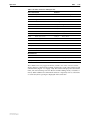
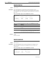
When a fault occurs in the main power supply or fan, the system LEDs on the
front and back panels of the AT-AR740 are flashed in a pattern that identifies
the fault (Table 1-5 on page 1-23). If RPS monitoring is on, the system LEDs also
flash to indicate failures in the RPS connection, power supply or fan. Multiple
faults are indicated by cycling through each error code.
Table 1-5: LED indications for fan an power supply faults on the ATAR740 router.
When this fault occurs... The System LED flashes in this pattern...
Software Release 2.0.1
C613-03018-00 REV A
Router fan failure
One flash: 0.2s on, 2s pause, (repeat)...
RPS fan failure
Two flashes: 0.2s on, 0.3s off, 0.2s on, 0.3s off, 2s pause,
(repeat)...
Router PSU failure
Three flashes: 0.2s on, 0.3s off, 0.2s on, 0.3s off,
0.2s on, 2s pause, (repeat)...
RPS PSU failure
Four flashes: 0.2s on, 0.3s off, 0.2s on, 0.3s off,
0.2s on, 0.3s off, 0.2s on, 2s pause, (repeat)...
RPS not connected
Five flashes: 0.2s on, 0.3s off, 0.2s on, 0.3s off,
0.2s on, 0.3s off, 0.2s on, 0.3s off,
0.2s on, 2s pause, (repeat)...
1-24
AR Series Router Reference Manual
Nonvolatile Storage (NVS)
The nonvolatile storage (NVS) module provides a facility to store information
so that it is not destroyed when the router is reset or powered off. The type of
information that may be stored in the NVS are module configuration tables,
interface configurations, patches and script files.
The NVS is organised as blocks of contiguous memory of varying size. A block
ID and an index uniquely identifies each block and an owner ID indicates
which module created the block. NVS blocks are normally maintained by the
modules that created them, but this can also be done manually.
The command:
SHOW NVS
displays information about each block in the NVS including ID, index, owner,
size, and creation date. The command:
SHOW NVS FREE
displays the amount of free space in the NVS and the size of the largest block
that can be created.
Blocks can be created using the command:
SET NVS CREATE
and deleted using the command:
SET NVS DELETE
All blocks can be deleted using the command:
SET NVS CLEAR_TOTALLY
Data in the NVS blocks can be displayed using the command:
SHOW NVS DUMP
and modified using the command:
SET NVS MODIFY
The router’s file subsystem provides a file-based interface to NVS memory,
allowing NVS to be used to store scripts and other files.
FLASH Memory
FLASH memory is a nonvolatile, reusable memory device that allows large
volumes of data (up to 8MB) to be stored in the router. The primary function of
FLASH memory in the router is to store multiple software releases, simplifying
the servicing and maintenance requirements of the router. Releases can be
remotely loaded into FLASH memory from any router port using the Loader
Module. Multiple software releases can be loaded and then individually
selected for use at runtime by the Install Module. Comprehensive management
features are provided to examine the state of the FLASH memory and to view
or modify the contents.
To enable FLASH memory to support applications other than just software
releases it is structured like a disk subsystem with files which can be created,
Software Release 2.0.1
C613-03018-00 REV A
Operation
1-25
deleted, read and written by any router module. Files can also be manipulated
directly using the command line interface. This allows FLASH to be used to
store any type of data, including releases, patches, configurations and logs.
Physical Characteristics
FLASH memory is a special type of nonvolatile memory which can be erased
and reprogrammed many times in-situ. FLASH memory has advantages over
other types of nonvolatile memory in that it has a very large storage capacity
and it does not require power from a battery to retain stored data. The main
limitations of FLASH memory are that it has a fixed erase block size, so
individual bytes can not be changed without first clearing a whole block of
data, and a limit on the number of erase cycles that can be performed.
However, the erase limit is very high, typically at least 100000 cycles, which
would allow three erases per day for 100 years before the limit was exceeded.
In the router, FLASH memory can be installed directly onto the system board
during manufacture, or subsequently as FLASH SIMM sticks mounted on the
80-pin SIMM connector.
The FLASH SIMM sticks used are specially designed for the router and must be
obtained from your distributor or reseller.
The presence and amount of FLASH memory installed is displayed using the
command:
SHOW SYSTEM
More detailed information about the FLASH memory can be displayed using
the command:
SHOW FLASH PHYSICAL
The File Subsystem
The file subsystem provides a consistent file-based interface to all physical
memory devices on the router used for data storage, including NVS and
FLASH memory. The file subsystem allows data, such as code releases, licence
information and configuration scripts, to be stored on the router in a file
structure and manipulated in the same way with the same commands,
regardless of whether the file is physically stored in NVS or FLASH.
File Naming Conventions
The file subsystem provides a flat file system—directories are not supported.
Files are uniquely identified by a file name of the form:
[device:]filename.ext
where:
■
Software Release 2.0.1
C613-03018-00 REV A
device specifies the physical memory device on which the file is stored, and
must be one of NVS or FLASH. If device is specified, it must be separated
from the rest of the file name by a colon (“:”). If device is not specified, the
default is FLASH.
1-26
AR Series Router Reference Manual
■
filename is a descriptive name for the file, and may be one to eight
characters in length. Valid characters are lowercase letters (a–z), uppercase
letters (A–Z), digits (0–9) and the hyphen character (-).
■
ext is a file name extension, one to three characters in length. Valid
characters are lowercase letters (a–z), uppercase letters (A–Z), digits (0–9)
and the hyphen character (-). The extension is used by the router to
determine the data type of the file and how to use the file (Table 1-6 on
page 1-26). If ext is specified, it must be separated from the filename portion
by a period (“.”)
Table 1-6: File extensions and file types.
Extension
File type/function
CFG
Configuration or boot script
HLP
Help file
HTM
HTML file used by the HTTP server
LIC
Licence information
LOG
Log file
MDS
Modem script
PAT
Patch
PAZ
Compressed patch
REL
Software release
REZ
Compressed release
SCP
Script
TXT
Generic text file
The following are examples of valid file names:
flash:config.scp
A script file.
flash:28-72.rel
Software Release 7.2.
nvs:28-70-02.pat
A patch for Software Release 7.0.
The following are examples of illegal file names:
flash:/sys/head_o.cfg
“/” is not a valid delimiter character, and
directories are not supported.
flash:headoffice.cfg
The filename is too long. A maximum of eight
characters is allowed.
Using Wildcards to Specify Groups of Files
The asterisk character (“*”) may be used as a wildcard character in some
commands to identify a groups of files to be processed by the command. A
wildcard must replace an entire field of the file name — device, filename or ext. A
wildcard can not be combined with other characters. The following are
examples of valid wildcard expressions:
flash:*.*
*:*.rel
The following is not a valid wildcard expression:
flash:28*.rel
Software Release 2.0.1
C613-03018-00 REV A
Operation
1-27
Working With Files
To display a directory of the files stored on the router, in both FLASH and NVS,
use the command:
SHOW FILE
To limit the display to certain files, use the command:
SHOW FILE=filename
filename may contain wildcard characters. Files can be permanently deleted
using the command:
DELETE FILE=filename
filename may contain wildcard characters. Files can be created using the
router’s built-in editor, using the command:
EDIT [filename]
or by downloading the file via HTTP, TFTP or ZMODEM, using the command:
LOAD FILE=filename
FLASH File System
The FLASH File System (FFS) provides additional functionality on top of that
provided by the file subsystem, to manage the peculiarities of FLASH
technologies. The additional functionality of the FFS includes:
■
Header and data integrity is ensured with a checksum mechanism.
■
All FLASH processes can recover from a power cycle without data loss.
■
Automatic recovery of deleted file space by the compaction process.
Information about the state of the FFS can be displayed using the command:
SHOW FLASH
Working with FFS Files
FFS files can be managed like any other file on the router, using the standard
file subsystem commands:
EDIT [filename]
DELETE FILE=filename
LOAD FILE=filename
SHOW FILE[=filename]
In addition, the following commands can be used to manage files stored in
FLASH memory. To display a directory of the files stored in FLASH memory,
use the command:
SHOW FFILE [CHECK]
If CHECK is specified then the file data checksum is also verified. This is
included as an option because it can take some time to complete a check on large
files. A file data check is also carried out each time a file is read by the system.
A FLASH file can be deleted with the command:
DELETE FFILE=filename
Software Release 2.0.1
C613-03018-00 REV A
1-28
AR Series Router Reference Manual
Wildcards are allowed in the filename and ext fields of the file name, but are not
allowed in the device field. The file is marked as deleted but the space
occupied by the file is not freed until the next compaction process.
The FLASH memory can be completely erased using the command:
CLEAR FLASH TOTALLY
This command totally erases all stored FLASH information and reformats the
FLASH file structure.
Compaction
FLASH memory has a granular erase structure which requires data to be
erased in large blocks rather than as individual bytes. To allow files to be
mapped onto this structure the FFS keeps track of the status of each file —
whether it is being written, is complete or is deleted. When the total amount of
FLASH memory used for deleted files reaches a preset limit a compaction
process is initiated. Compaction searches through the FLASH memory copying
good files to a new location. As soon as all the good files within an erase block
have been copied the block is cleared. This results in any deleted files present
in the block being cleared, freeing up space for new files. If there is a large
amount of FLASH memory in use then the compaction process can take several
seconds to complete. However, FLASH memory operations continue to operate
without being affected by the compaction process.
While FLASH is compacting, do not restart the switch or use any commands
that affect the FLASH file subsystem. Do not restart the switch, or create, edit,
load, rename or delete any files until a message confirms that FLASH file
compaction is completed. Interrupting flash compaction may result in damage
to files.
Compaction can also be manually initiated using the command:
ACTIVATE FLASH COMPACTION
FFS Messages
Some FFS processes generate messages in the system log (displayed with the
SHOW LOG command on page 23-34 of Chapter 23, Logging Facility) which
include FFS message codes. See “FLASH File System Message Codes” on
page C-6 of Appendix C, Reference Tables for a complete list of the possible codes
and their meanings.
The Built-in Editor
The router has a built-in full-screen text editor for editing ASCII text files
stored on the router file subsystem.
The editor uses VT100 command sequences and should only be used with a
VT100-compatible terminal, terminal emulation program or Telnet client. The
VT100 screen only supports 24 lines, unlike a PC. Lines 1–23 are used to
display the text of the file being edited, and line 24 is used as the status bar and
Software Release 2.0.1
C613-03018-00 REV A
Operation
1-29
command line (Figure 1-3 on page 1-29). The status bar displays the current file
name, line and column position in the file and the editing mode (overstrike or
insert). When additional command information is required, such as a file name
or search text, then a prompt is displayed in the status bar.
Figure 1-3: The editor screen layout.
The editor is invoked with the command:
EDIT [filename]
The file name is optional as a file can be loaded, or a new file can be created
from within the editor itself. The editor is currently limited to editing one file at
a time. To overcome this limitation use the cut and paste facility to transfer text
between files.
Before starting the editor make sure your terminal, terminal emulation program
or Telnet client is 100% compatible with a VT100 terminal.
Help can be obtained at any time while in the editor by pressing [Ctrl/K,H];
that is, holding down the Ctrl key and pressing in turn the K key then the H
key.
HTTP Client and Server
The router has a built-in HTTP client and server. The HTTP server is
compatible with any HTTP/1.1-compliant browser and allows the router to
serve HTML pages out of FLASH memory to a remote web browser. The HTTP
server is enabled by default. To disable the HTTP server, or to enable the HTPP
server after it has been disabled, use the commands:
DISABLE HTTP SERVER
ENABLE HTTP SERVER
Software Release 2.0.1
C613-03018-00 REV A
1-30
AR Series Router Reference Manual
When a user attempts to access the router via a web browser, the HTTP server
will request authentication from the browser. The browser will prompt the user
for a username and password (Figure 1-4 on page 1-30).
Figure 1-4: Logging in to the router from a web browser.
The username and password entered by the user must match a user defined in
the User Authentication Database (see “The User Authentication Database” on
page 1-13).
By default, the router’s homepage is homepage.htm. This is the page the HTTP
server returns when it receives a request that does not specify a particular
page, and when no web-based GUI is installed on the router. If there is a webbased GUI, the router will return the GUI homepage when a request does not
specify a page. To change the home page to another file stored in the routers’s
FLASH memory, use the command:
SET HTTP SERVER HOMEPAGE=filename.htm
All GET, configure and monitor requests, and authorisation failures are logged
to the Logging Facility (see Chapter 23, Logging Facility). Debugging can be
enabled or disabled using the commands:
ENABLE HTTP DEBUG={ALL|AUTH|MSG|SESSION}
DISABLE HTTP DEBUG={ALL|AUTH|MSG|SESSION}
Debug messages display authorisation attempts, HTTP GET and POST
requests and responses, and TCP state changes. The currently enabled
debugging options can be displayed using the command:
SHOW HTTP DEBUG
The command:
RESET HTTP SERVER
restarts the HTTP server, disables debugging and clears all counters.
To display the current status of the HTTP server, use the command:
SHOW HTTP SERVER
To display information about the currently active sessions on the HTTP server,
use the command:
SHOW HTTP SESSION
The HTTP client enables the router to act as a browser by sending HTTP GET
or POST requests to another HTTP server. The HTTP client is used by the
Software Release 2.0.1
C613-03018-00 REV A
Operation
1-31
Configuration Wizard to download updates from a support web site. To
display the current status of the HTTP client, use the command:
SHOW HTTP CLIENT
Resolving Uniform Resource Locators (URLs)
When the HTTP server receives a request for a URL, it uses the following
procedure to resolve the URL:
■
If the URL matches the name of a file stored in the router’s FLASH
memory, the file will be loaded and sent to the browser.
■
If the URL does not match the name of a file stored in FLASH, the HTTP
server searches a list of dynamically generated HTML pages for a match. If
a match is found the page is generated and sent to the browser.
■
If the URL does not match the name of a file stored in FLASH or the name
of a dynamically generated HTML page, the HTTP server will return the
HTML error 404, indicating the URL could not be found.
Mail Subsystem
The router has a built-in email client and SMTP (Simple Mail Transfer Protocol)
server to enable email messages to be sent from the router to remote mail
systems using SMTP. The email client generates messages that comply with
RFC 822 (“Standard for the Format of ARPA Internet Text Messages”). The SMTP
server implements RFC 821 (“Simple Mail Transfer Protocol“) for the
transmission of mail messages.
The SMTP server can only transmit email messages; it can not accept email messages
from other mail systems.
A mail message is transmitted using the command:
MAIL TO=destination {FILE=filename|MESSAGE=message}
[SUBJECT=subject] [ETRN=mail-domain]
from the router’s command line prompt or from a script. Messages can also be
transmitted automatically by the Trigger Facility (Chapter 20, Trigger Facility),
the Logging Facility (Chapter 23, Logging Facility) and the firewall (Chapter 31,
Firewall).
The body of the message may contain either a single character string or the
contents of a file in the router’s NVS or FLASH memory.
The current state of the mail subsystem and the messages queued for
transmission can be displayed using the command:
SHOW MAIL
Messages that are queued awaiting transmission can be deleted using the
command:
DELETE MAIL=id
Software Release 2.0.1
C613-03018-00 REV A
1-32
AR Series Router Reference Manual
The progress of mail messages can be monitored using the mail subsystem’s
debugging option, which is enabled or disabled with the commands:
ENABLE MAIL DEBUG
DISABLE MAIL DEBUG
Configuration Examples
The following procedures illustrate the steps required to configure the mail
subsystem and transmit email messages. It is assumed that IP has already been
enabled and correctly configured on the router.
To configure the mail subsystem:
1.
Configure a DNS Server.
Configure the IP address of the DNS server that the mail subsystem will
use to resolve email addresses into IP addresses. Without a DNS server the
mail subsystem will not function.
SET IP NAMESERVER=192.168.5.3
2.
Configure the mail host name.
Configure the host name used by the mail subsystem when
communicating with other mail systems. Normally this is the fully
qualified domain name of the router. Without a host name the mail
subsystem will not function.
SET MAIL HOSTNAME=ho1.company.com
3.
Check the configuration.
Check that the mail subsystem is correctly configured and enabled.
SHOW MAIL
To send a file via email from the router’s command prompt:
1.
Send the file as the body of a mail message.
Text format files (files with .CFG, .SCP and .TXT extensions) can be
transferred from the router to a remote user in the body of an email
message. For example, configuration scripts can be sent to a central host for
management and change control. In this example, the file boot.cfg is sent
to the network administrators email address [email protected]:
MAIL [email protected] SUBJECT=”Boot script for
ho1.company.com” FILE=boot.cfg
2.
Check the progress of the message.
The progress of the message as it is transmitted to the remote mail system
can be monitored using the command:
SHOW MAIL
To transmit messages automatically using the Trigger Facility:
1.
Create a script to generate a mail message.
Create a script called mailcpu.scp using the router’s built-in editor that
sends a message to the network administrator:
EDIT mailcpu.scp
Software Release 2.0.1
C613-03018-00 REV A
Operation
1-33
The script contains the following line:
MAIL [email protected] SUBJECT=”WARNING: Load high”
MESSAGE=”CPU utilisation exceeded 80%”
Note that it is not necessary to identify the router in either the Subject field
or the message as the mail system automatically inserts the router’s host
name in the From field of the message header.
2.
Create a trigger to activate the script.
Enable the trigger module and create a trigger to activate the script when
the router’s CPU utilisation rises above 80%:
ENABLE TRIGGER
CREATE TRIGGER=1 CPU=80 DIRECTION=UP SCRIPT=mailcpu.scp
SHOW TRIGGER=1
Software Releases and Patches
Prior to Software Release 6.8, system code resided in a set of Erasable
Programmable Read Only Memories (EPROMs). At router startup the system
code was copied to RAM to allow code patches to be made. Patches could be
loaded in to nonvolatile storage (NVS) which would overlay the system code
in RAM.
From Software Release 6.8, software releases can be stored in FLASH and
loaded into RAM from FLASH without changing EPROMs. Patches can be
stored in and loaded from either NVS or FLASH. The router will boot from any
designated software release in FLASH, or as a last resort, from the software
release in EPROM.
From Software Release 7.2, software releases and patches are also available as
compressed release files. A compressed release file is substantially smaller than
the equivalent standard release file, requires less FLASH memory to store, and
can be downloaded to the router in less time. The disadvantage is that the
router startup process takes longer (5–25 seconds) when booting from a
compressed release.
From Software Release 7.6.0, software releases have a new numbering scheme.
A release is now identified by a number of the format
<major>.<minor>.<interim>. The release whose interim release number is "0" is
known as the "base release". For example, Software Release 7.6.0 is the base
release of 7.6, Software Release 7.6.1 is the first interim release of 7.6.
Releases
A software release contains a copy of the system software that executes on the
router. Releases are given numbers that look like “7.6.0”. In this case the major
release number is “7”, the minor release number is “6” and the interim release
number is “0”. A release can be stored either in EPROM or in FLASH. Releases
can not be stored in NVS because the amount of NVS available in the router is
not large enough to hold an entire release.
A standard release is a single file with a name of the form:
mm-rrr.REL
Software Release 2.0.1
C613-03018-00 REV A
1-34
AR Series Router Reference Manual
where mm identifies the router model (Table 1-7 on page 1-34) and rrr is the
release number (e.g. 761 for Software Release 7.6.1).
Table 1-7: Software Release filename formats
Filename Format
Router Model
8-rrr.REL
AR300 Series routers
52-rrr.REL
AR720 router
18-rrr.REL
Network iQ 1800 Series routers
28-rrr.REL
Network iQ 1000/2800/3000/3800 Series routers
48-rrr.REL
Network iQ 4800 Series routers
There are two methods of providing compressed releases, depending on the
release number of the base EPROMs in the router. For Software Release 7.4 and
later, compressed releases are supported by the base EPROMs and the file
required for a compressed release is:
mm-rrr.REZ
For Software Release 7.2, a special download release is required. The files
required are:
mm-rrrC.REL
mmooDrrr.REL
where oo is the release number of the base EPROMs. Releases prior to Software
Release 7.2 do not support compressed releases.
Releases stored in FLASH are subject to licencing. A FLASH release may be
downloaded into the router, but can not be used until the correct licence
information is entered.
Licence information will be supplied by your distributor or reseller with each software
release. For compressed releases on EPROM releases prior to Software Release 7.4, a
separate licence is required for each of the files mm-rrC.REL and mmooDLrr.REL.
The licence is encoded and is specific to a particular router and a particular
release. A licences may be a FULL licence or a 30-day licence. A 30-day licence
will expire after 30 days; a FULL licence does not have an expiry date. To
enable a release licence, use the command:
ENABLE RELEASE
To disable a release licence, use the command:
DISABLE RELEASE
The current status of release licences in the router can be shown with the
command:
SHOW RELEASE
A number of releases can be stored in the router at once. The EPROM release is
always available, and one or more releases may be stored in FLASH. The router
contains INSTALL information that specifies which release (EPROM or one of
the FLASH releases) is to be loaded at boot. This information may be changed
at any time. The INSTALL information can be overridden so that the release
stored in EPROM is loaded.
Software Release 2.0.1
C613-03018-00 REV A
Operation
1-35
A software release is specific to a particular router series. It is not possible to
run a release on any router series other than that for which the release was
made. The same router release will, however, run on all models in the same
series. If an attempt is made to load the wrong software release into the router
the boot process will fail.
Patches
A router patch contains changes to the router software. A patch usually
contains fixes to software errors, although enhancements to the software may
sometimes be released as patches. Patches are identified by names like
“7.6.0-2”. In this case, “7.6.0” is the release that the patch modifies, and “2” is a
version number that identifies the patch in a series (1, 2, 3...) of patches. Patches
are specific to a particular release, and thus to a particular router series. Any
attempt to use a patch with a non-matching release will result in failure.
A standard patch is a single file with a name of the form:
mmrrr-pp.PAT
where mm identifies the router model (Table 1-7 on page 1-34), rrr is the release
number (e.g. 761 for Software Release 7.6.1), and pp is the version number of
the patch.
Compressed patches are supported on routers running a base EPROM release
of Software Release 7.4 or later. The patch consists of a single file:
mmrrr-pp.PAZ
Compressed patches are not supported for routers running base EPROMs prior
to Software Release 7.4 and running a compressed release.
Patches may be loaded into either FLASH, or, if the patch is small enough, into
NVS. There is no difference between a patch file loaded into FLASH and a patch
file loaded into NVS; the difference lies in the command used to load the file.
The INSTALL information that specifies the release to use also contains
information about the patch. It is possible to load a router with a number of
different patches, but only one patch can be run at a time.
Router Startup Operations
When the router boots, the following sequence of operations is performed:
Software Release 2.0.1
C613-03018-00 REV A
1.
Perform startup self tests.
2.
Perform the install override option.
3.
Load the EPROM release as the INSTALL boot.
4.
Inspect and check INSTALL information.
5.
Load the required EPROM or FLASH release as the main boot.
6.
Start the router.
7.
Execute the boot script, if one has been configured.
1-36
AR Series Router Reference Manual
If a terminal is connected to port 0, a series of status and progress messages,
similar to those shown in Figure 1-5 on page 1-36, are displayed during the
startup process.
Figure 1-5: Router startup messages.
INFO:
INFO:
PASS:
INFO:
PASS:
PASS:
INFO:
INFO:
Force
INFO:
INFO:
INFO:
Self tests beginning.
RAM test beginning.
RAM test, 4096k bytes found.
BBR tests beginning.
BBR test, 128k bytes found.
BBR test. Battery OK.
Self tests complete
Downloading router software.
EPROM download (Y) ?
Initial download succeeded
Executing configuration script <boot.cfg>
Router startup complete
Manager >
The startup self tests check the basic operation of the router. A router that
passes these tests should be able to at least proceed far enough to perform the
load of the EPROM release and to start operating.
The install override option is designed to allow a mandatory router boot from
the EPROM release. The message:
Force EPROM download (Y)?
is displayed on the terminal connected to port 0 and the router pauses. If a key
is not pressed within a few seconds, the startup process will continue and all
steps in the sequence will be executed. If the [Y], [S] or [Ctrl/D] key on the
terminal is pressed immediately after the message is displayed, the router
startup process can be altered (Table 1-8 on page 1-36).
Table 1-8: Router startup sequence keystrokes.
Pressing key...
Forces the router to...
Y
Load the EPROM release, with no patch, and skip straight to step 6.
S
Start with the default configuration. Any boot script or NVS
configuration is ignored.
N
Configure from NVS, ignoring any boot script.
[Ctrl/D]
Enter diagnostics mode.
The EPROM release is always loaded first when starting the router. This release
contains all the code required to obtain and check the INSTALL information.
This first boot is known as the INSTALL boot. The INSTALL information is
inspected and the router set up to perform another load. Even if the actual
release required is the EPROM release, another load is always performed. At
this point the patch load, if required, is also performed.
The router startup occurs immediately after the install override option, or after
the INSTALL information check. This performs a full startup of router software
and initiates the normal operation of the router.
Finally, if a boot script has been defined, the script is executed.
Software Release 2.0.1
C613-03018-00 REV A
Operation
1-37
Downloading Releases and Patches into the Router
The LOADER module is responsible for loading and storing releases, patches
and other files into either NVS or FLASH. The LOADER module uses the
Trivial File Transfer Protocol (TFTP), Hypertext Transfer Protocol (HTTP) or
ZMODEM over an asynchronous port, to retrieve files from a network host.
The FFS and NVS modules are used to create, write and destroy release and
patch files.
The loader can be configured with the command:
SET LOADER
This command sets default values for the name of the file to load, the network
host to load it from, and the memory location in which to store the file. These
default values can be overridden when the load actually takes place. A time
delay between initiating a load and the start of the load can also be configured.
The configuration of the LOADER module can be displayed with the command:
SHOW LOADER
This shows the default configuration for the LOADER module as well as the
status of any current file transfer.
To actually initiate a load, use the command:
LOAD
This command will use either the default values for the LOADER module or
the values specified on the command line. The command:
SHOW LOADER
displays the progress of the load. The current load can be stopped at any time
using the command:
RESET LOADER
leaving the LOADER module ready to load again. Only one file can be loaded
at a time. Another load can not be initiated while loading is in progress.
Once the release or patch file has been loaded, its presence can be checked
with the command:
SHOW FILE
for files in FLASH, or using the command:
SHOW PATCH
for files in NVS. A release or patch file can be removed with the command:
DELETE FILE
for files in FLASH, or with the command:
DESTROY PATCH
for files in NVS.
Files to be loaded by the LOADER module must be resident on a TFTP server
accessible via the network, or accessible via the ZMODEM protocol over an
asynchronous port. Release and patch files are ASCII files, and consist of a
header followed by a sequence of Motorola S-records containing the actual
code for the release or patch. The header has a standard format, which
provides information about the release or patch to the router.
Software Release 2.0.1
C613-03018-00 REV A
1-38
AR Series Router Reference Manual
The header in the release or patch file should not be altered. At best, this will
cause the file load or install to fail, at worst the router could be put into a state
where it will not boot correctly until field service action is taken.
Install Information
The INSTALL module is responsible for maintaining install information and
loading the correct install at boot. An install is a record identifying a release and
an optional patch. Three installs are maintained by the INSTALL module,
temporary, preferred and default.
The default install is the install of last resort. The release for the default install
can not be changed by the manager and is always the EPROM release. The
patch for the default install may be set by the manager.
The temporary and preferred installs are completely configurable. Both the
release and an associated patch may be set. The release may be EPROM or a
release stored in FLASH.
The three different installs are required to handle the following situations:
■
A default install is required to handle the case when only the EPROM
release is present.
■
A temporary install is required to allow a release and/or patch to be
loaded once only, in case it causes a router crash.
■
A preferred install is required because the default install can not be
anything other than the EPROM.
The install information is inspected in a strict order. The temporary install is
inspected first. If this install information is present, the temporary install is
loaded. At the same time, the temporary install information is deleted. This
ensures that if the router reboots immediately as the result of a fatal condition
caused by the temporary install, the temporary install will not be loaded a
second time.
If there is no temporary install defined, or the install information is invalid, the
preferred install is inspected. If present, this install is loaded. The preferred
install information is never deleted.
If neither temporary nor preferred installs are present, the default install is
used. The default install will always be present in the router, because if, for
some reason, it is not, the INSTALL module will restore it.
The preferred install should not be set up with an untested release or patch. It
is advisable to install new releases or patches as the temporary install, and
when the router boots correctly, to then set up the preferred install with the new
release or patch.
To change the install information in the router, use the command:
SET INSTALL
To delete a particular install (except the default install) use the command:
DELETE INSTALL
Software Release 2.0.1
C613-03018-00 REV A
Operation
1-39
To display the current install information, including which install is currently
running in the router, and how the install information was checked at the last
reboot, use the command:
SHOW INSTALL
Examples
Installing a Standard Release using TFTP
This example assumes that the router is correctly configured to allow TFTP to
function. This means that IP has been configured and the router is able to
communicate with the designated TFTP server. The TFTP server is assumed to
be functioning correctly and the release and patch files are assumed to be
present in the server’s TFTP directory. The router has no release or patch files,
and is running the EPROM Software Release 7.6.0. The IP address of the server
is 172.16.1.1. The name of the release file being loaded is 8-761.rel and the
name of the patch file is 8761-01.pat.
To install a standard release:
1.
Configure the loader.
The LOADER module is set up with defaults to make the process of
downloading files in future simpler. All release and patch files in this
router will be stored in FLASH.
SET LOADER SERVER=172.16.1.1 DEST=FLASH
2.
Download the release file to the router.
The release file is downloaded to the router with the command:
LOAD FILE=8-761.REL
The process of downloading a release file can take some time, even if the
router and the TFTP server are connected by high speed links. An
indicative time for downloading a release over Ethernet is 5 to 10 minutes.
The progress of the download can be monitored with the command:
SHOW LOAD
When the download has completed, the presence of the file in FLASH can
be displayed with the command:
SHOW FILE
This shows the file 8-761.rel is present.
3.
Enter the licence information for the release.
To allow this file to be used as a release file, a licence must be entered with
the command:
ENABLE RELEASE=8-761.REL PASSWORD=ce645398fbe NUMBER=7.6.1
The password is provided by your distributor or reseller and is unique for
the release number (in this case 7.6.1), the file name and the router’s serial
number.
4.
Test the release.
The release can now be tested, using the command:
SET INSTALL=TEMPORARY RELEASE=8-761.REL
Software Release 2.0.1
C613-03018-00 REV A
1-40
AR Series Router Reference Manual
The install information can be checked with the command:
SHOW INSTALL
The router is then rebooted, and the install is checked again. This display
should indicate, in the install history, that the temporary install was
loaded.
5.
Make the release the default (permanent) release.
If the router operates correctly with the new release, the release may be
made permanent with the command:
SET INSTALL=PREFERRED RELEASE=8-761.REL
Every time the router reboots from now on, the new release will be loaded
from FLASH.
Installing a Standard Patch
This example illustrates how to install a standard patch on a router.
To install a standard patch:
1.
Download the patch file to the router.
Download the patch file 8761-01.pat into the router with the command:
LOAD FILE=8761-01.PAT
This download takes a lot less time than the download of the release file,
and is verified by showing the file in FLASH.
2.
Test the patch.
As with the release, the patch should first be checked by incorporating it
into a temporary install, with the command:
SET INSTALL=TEMPORARY RELEASE=8-761.REL PATCH=8761-01.PAT
The router is then rebooted, and the install is checked again. This display
should indicate, in the install history, that the temporary install was
loaded.
3.
Make the patch the default (permanent) patch.
If the router operates correctly with the new patch, the patch may be added
to the preferred install with the command:
SET INSTALL=PREFERRED PATCH=8761-01.PAT
The release information is still present in the preferred install and does not
have to be re-entered.
Installing a Compressed Release
This example is identical to the previous example, except that a compressed
release and patch are installed.
To install a compressed release:
1.
Configure the loader.
The LOADER module is set up with defaults to make the process of
downloading files in future simpler. All release and patch files in this
router will be stored in FLASH.
SET LOADER SERVER=172.16.1.1 DEST=FLASH
Software Release 2.0.1
C613-03018-00 REV A
Operation
1-41
2.
Download the release files to the router.
The compressed release files are downloaded to the router with the
commands:
LOAD FILE=8-761.REZ
The process of downloading a release file can take some time, even if the
router and the TFTP server are connected by high speed links. An
indicative time for downloading a release over Ethernet is 5 to 10 minutes.
The progress of the download can be monitored with the command:
SHOW LOAD
When the download has completed, the presence of the files in FLASH can
be displayed with the command:
SHOW FILE
This shows the file 8-761.rez is present.
3.
Enter the licence information for the release.
To allow these file to be used as release files, a licence must be entered for
each file, with the commands:
ENABLE RELEASE=8-761.REZ PASSWORD=ce645398fbe NUMBER=7.6.1
The password is provided by your distributor or reseller and is unique for
the release number (in this case 7.6.1), the file name and the router’s serial
number.
4.
Test the release.
The release can now be tested, using the command:
SET INSTALL=TEMPORARY RELEASE=8-761.REZ
The install information can be checked with the command:
SHOW INSTALL
The router is then rebooted, and the install is checked again. This display
should indicate, in the install history, that the temporary install was
loaded.
5.
Make the release the default (permanent) release.
If the router operates correctly with the new release, the release may be
made permanent with the command:
SET INSTALL=PREFERRED RELEASE=8-761.REZ
Every time the router reboots from now on, the new release will be loaded
from FLASH.
Installing a Compressed Patch
This example illustrates how to install a compressed patch on a router running
base EPROMs for Software Release 7.6.1 or later.
To install a compressed patch:
1.
Download the patch files to the router.
Download the patch file 8761-01.paz into the router with the command:
LOAD FILE=8761-01.PAZ
This download takes a lot less time than the download of the release files,
and is verified by showing the files in FLASH.
Software Release 2.0.1
C613-03018-00 REV A
1-42
AR Series Router Reference Manual
2.
Test the patch.
As with the release, the patch should first be checked by incorporating it
into a temporary install, with the command:
SET INSTALL=TEMPORARY RELEASE=EPROM PATCH=8761-01.PAZ
The router is then rebooted, and the install is checked again. This display
should indicate, in the install history, that the temporary install was
loaded.
3.
Make the patch the default (permanent) patch.
If the router operates correctly with the new patch, the patch may be added
to the preferred install with the command:
SET INSTALL=PREFERRED RELEASE=EPROM PATCH=8761-01.PAZ
The release information is still present in the preferred install and does not
have to be re-entered.
Special Feature Licences
A special feature licence and password are required to activate some special
features over and above the standard software release. Typically, these special
features are covered by government security regulations. Special feature
licences and passwords are quite separate and distinct from the standard
software release licences and passwords.
A special feature licence may be either a 30-day trial license or a full (unlimited
time) license and is specific to a router serial number. Special feature licences
can not be transferred from one router to another.
The password for a special feature licence is a string of at least 16 hexadecimal
characters, and encodes the special feature or features covered by the license,
the licence type (30-day trial licence or full licence) and the router serial
number. The password information is stored in the router’s FLASH memory.
Special feature licences are enabled and disabled with the commands:
ENABLE FEATURE=featurename PASSWORD=password
DISABLE FEATURE={featurename|index}
A list of current special feature licences can be displayed with the command:
SHOW FEATURE[={featurename|index}]
Passwords must be ordered from your local distributor or reseller. You must specify the
special features to be licenced and the serial number(s) of the router(s) on which the
special feature licences are to be enabled.
Software Release 2.0.1
C613-03018-00 REV A
Operation
ACTIVATE FLASH COMPACTION
1-43
Command Reference
This section describes the commands available on the router to support day-today operational and management activities.
See “Conventions” on page lxxi of Preface for details of the conventions used to
describe command syntax. See Appendix B, Messages for a complete list of
messages and their meanings.
ACTIVATE FLASH COMPACTION
Syntax
Description
ACTIVATE FLASH COMPACTION
This command activates the FLASH compaction process. Compaction is the
process of cleaning up garbage (deleted files) by searching through FLASH
memory copying valid files to a new block and erasing the old blocks. The
compaction process normally occurs automatically when the amount of
garbage reaches a preset limit, so manual compaction is not required for
normal operation. This command can be used to recover garbage space before
the automatic compaction threshold is reached.
Compaction is required because the FLASH memory has a granular erase
structure which requires data to be erased in large blocks rather than as
individual bytes. To allow files to be mapped onto this structure the FFS keeps
track of the status of each file — whether it is being written, is complete or is
deleted. When the total amount of FLASH memory used for deleted files
reaches a preset limit a compaction process is initiated. Compaction searches
through the FLASH memory copying good files to a new location. As soon as
all the good files within an erase block have been copied the block is cleared.
This results in any deleted files present in the block being cleared, freeing up
space for new files. If there is a large amount of FLASH memory in use then the
compaction process can take several seconds to complete. However, FLASH
memory operations continue to operate without being affected by the
compaction process.
While FLASH is compacting, do not restart the switch or use any commands
that affect the FLASH file subsystem. Do not restart the switch, or create, edit,
load, rename or delete any files until a message confirms that FLASH file
compaction is completed. Interrupting flash compaction may result in damage
to files.
While compaction is underway the command:
SHOW FLASH
will indicate an FFS global operation of “compacting”. When compaction is
complete the global operation will return to “none”.
See Also
Software Release 2.0.1
C613-03018-00 REV A
SHOW FLASH
1-44
ADD ALIAS
AR Series Router Reference Manual
ADD ALIAS
Syntax
ADD ALIAS=name STRING=substitution
Where:
Description
■
name is a character string 1 to 132 characters in length. It may contain any
printable character. If name contains spaces it must be enclosed in double
quotes. It is case-sensitive.
■
substitution is a character string 1 to 132 characters in length. It may contain
any printable character. If substitution contains spaces it must be enclosed
in double quotes. It is case-sensitive.
This command adds a new alias for a longer character sequence. When the user
presses [Enter] to execute the command line, the command processor first
checks the command line for aliases and substitutes the replacement text. The
command line is then parsed and processed normally. Alias substitution is not
recursive—the command line is scanned only once for aliases. An alias may
represent either part of a command, or a complete command.
The ALIAS parameter specifies the name of the alias. This is the text that the
user enters on the command line.
The STRING parameter specifies the substitution string. When the command
processor parses the command line, all occurrences of the alias are replaced by
this string.
Examples
To create an alias “df” that expands to “delete file=1-190.rez”, use the
command:
add alias=df string=”delete file=1-190.rez”
Thereafter, the following commands are equivalent:
df
del file=1-190.rez
See Also
ADD ALIAS
DELETE ALIAS
Software Release 2.0.1
C613-03018-00 REV A
Operation
ADD RADIUS SERVER
1-45
ADD RADIUS SERVER
Syntax
ADD RADIUS SERVER=ipadd SECRET=secret PORT=port-number
ACCPORT=port-number
where:
Description
■
secret is a character string, 1 to 63 characters in length. It may contain
uppercase letters (A–Z), lowercase letters (a–z), digits (0–9) and the
underscore character (“_”). If the string contains spaces it must be enclosed
in double quotes. It is case-sensitive.
■
ipadd is an IP address in dotted decimal notation.
■
port-number is a port number in the range 0 to 65535.
This command adds a RADIUS server to the list of known RADIUS servers.
RADIUS servers are used for user authentication.
The SERVER parameter specifies the IP address of the RADIUS server, in
dotted decimal notation. The server must not already be in the list of known
RADIUS servers. If SERVER is specified, but PORT and ACCPORT are not,
then the RADIUS server is used for both authentication and accounting, and
requests are sent to the default ports (1645 and 1646). Use the PORT and
ACCPORT parameters to prevent the RADIUS server being used for
authentication or accounting, or to specify a different port number to use.
The SECRET parameter specifies a shared secret used in communications
between the router and the RADIUS server. The secret is used by the router to
encrypt the password field in authentication requests sent to the RADIUS
server, and by the RADIUS server to authenticate the router’s request. The
secret is case-sensitive.
The PORT parameter specifies a non-standard port number for communication
with the RADIUS server. Setting the port number to zero means that the server
will not be used for RADIUS authentication (it may only be required for
RADIUS accounting).
The ACCPORT parameter specifies a port number for communication with the
RADIUS server running RADIUS accounting (RFC 2139). Setting the port
number to zero means that the server will not be used for RADIUS accounting
(it may only be required for RADIUS authentication).
By default the RADIUS server uses port number 1645 to connect to RADIUS
servers for authentication, and port number of 1646 for RADIUS accounting.
The RADIUS accounting port is not the official port number (1813) but is the
port number used by a number of commonly available packages.
Examples
To add a RADIUS server with an IP address of 192.168.17.11 and “Valid8Me” as
the shared secret, use the command:
ADD RADIUS SERVER=192.16817.11 SECRET=Valid8Me
To add a RADIUS server for accounting only, with an IP address of
192.168.17.12 and “Valid8Me” as the shared secret, use the command:
ADD RADIUS SERVER=192.16817.11 SECRET=Valid8Me PORT=0
ACCPORT=1813
Software Release 2.0.1
C613-03018-00 REV A
1-46
ADD TACACS SERVER
See Also
AR Series Router Reference Manual
DELETE RADIUS SERVER
SHOW RADIUS
ADD TACACS SERVER
Syntax
ADD TACACS SERVER=ipadd
where:
■
Description
ipadd is an IP address in dotted decimal notation.
This command adds a TACACS server to the list of TACACS servers used for
authenticating login names.
The SERVER parameter specifies the IP address of the server in dotted decimal
notation. An unlimited number of TACACS servers may be defined, although
two or three would be a sensible maximum number.
Examples
To add a TACACS server with the IP address 172.16.8.5 use the command:
ADD TACACS SERVER=172.16.8.5
See Also
DELETE TACACS SERVER
SHOW TACACS SERVER
ADD USER
Syntax
ADD USER=login-name PASSWORD=password
[CALLINGNUMBER=number] [CBNUMBER=e164number]
[DESCRIPTION=description] [PRIVILEGE={USER|MANAGER|
SECURITYOFFICER}] [TELNET={YES|NO}] [IPADDRESS=ipadd]
[IPXNETWORK=network] [NETMASK=ipadd] [MTU=40..1500]
where:
■
login-name is a character string, 1 to 64 characters in length. Valid characters
are uppercase letters (A–Z), lowercase letters (a–z), and decimal digits (0–9).
The string may not contain spaces.
■
password is a character string, 1 to 32 characters in length. Valid characters
are any printable character. If the string contains spaces it must be enclosed
in double quotes.
■
number is an ISDN phone number, 1 to 32 characters in length. Valid
characters are any printable characters. If the string contains spaces it must
be enclosed in double quotes.
■
e164number is a valid phone number. It may contain digits (0–9) and should
be a valid phone number as described in CCITT standard E.164.
■
description is a character string, 1 to 23 characters in length. Valid characters
are any printable character. If the string contains spaces it must be enclosed
in double quotes.
Software Release 2.0.1
C613-03018-00 REV A
Operation
ADD USER
Description
■
ipadd is an IP address in dotted decimal notation.
■
network is a valid Novell network number, expressed as a hexadecimal
number. Leading zeros may be omitted.
1-47
This command adds a user to the User Authentication Database. The USER
parameter specifies the login name for the user. It is case insensitive.
The PASSWORD parameter specifies the password for the user. The password
is case sensitive. It is intended that the PASSWORD parameter be used to set an
initial password for the user and that the user will change it to some string
known only to the user, using the SET PASSWORD command on page 1-89. A
password set with the SET PASSWORD command may contain any printing
character. A configurable minimum password length is enforced. The default is
6 characters.
The CALLINGNUMBER parameter specifies the calling number to be used to
authenticate incoming calls from L2TP and ISDN services that provide caller
ID information. While any printable characters will be accepted for this
parameter, the calling number it is to match is likely to contain only decimal
digits. Any other characters used in this parameter are unlikely to match the
calling number of an incoming call.
The CBNUMBER parameter specifies the ISDN phone number to use when
making a call back to a remote user using the PPP callback facility.
The DESCRIPTION parameter specifies a descriptive text for the entry, such as
the full name and location of the user. This string may contain any printing
character and the case is preserved in output.
The PRIVILEGE parameter specifies the privilege level for the user. The default
is USER. A user with USER privilege has access to only a limited subset of
commands, generally commands that only affect the user’s own session or
asynchronous port. A user with MANAGER privilege has access to the
complete router command set when the router is operating in normal mode, or
a subset of commands when the router is operating in security mode. A user
with SECURITY OFFICER privilege has access to the full set of commands, and
in particular, can access security commands while the router is operating in
security mode.
The TELNET parameter specifies whether or not the user is permitted to use
the TELNET command on page 11-24 of Chapter 11, Terminal Server to Telnet to
another host, or the CONNECT command on page 11-13 of Chapter 11, Terminal
Server to access a Telnet service when logged in via Telnet.
The IPADDRESS parameter specifies an IP address for the user. The value must
be a valid IP address in dotted decimal form.
The IPXNETWORK parameter specifies the Novell network number assigned
to the user accessing a Novell internetwork. See Chapter 18, Asynchronous Call
Control for more information. The network number may be cleared by setting
IPXNETWORK to NONE instead of a network number. The default is NONE.
The NETMASK parameter specifies an IP network mask for the user. The value
must be a valid IP address in dotted decimal form.
The MTU parameter specifies a Maximum Transmission Unit value for the
user. The value must be a decimal integer in the range 40 to 1500 inclusive.
Software Release 2.0.1
C613-03018-00 REV A
1-48
ADD USER RSO
AR Series Router Reference Manual
The IPADDRESS, NETMASK and MTU parameters are only required if the
user is to login in order to make a PPP or SLIP connection to the router over a
modem connected to an asynchronous port.
Examples
To add a user with the login name “BRUCE”, the password “sbfd4Q” and
MANAGER privilege, use the command:
ADD USER=BRUCE DESCRIPTION=“Bruce Wilson” PASSWORD=sbfd4Q
PRIVILEGE=MANAGER
To add a user with the login name “ACCOUNTS”, the password “Cash4Cast”,
and USER privilege, and specify an IP address, network mask and MTU so that
the user can make SLIP connection to the router, use the command:
ADD USER=ACCOUNTS DESCRIPTION=“Accounting Data Entry”
PASSWORD=Cash4Cast PRIVILEGE=USER IPADDRESS=192.168.35.17
NETMASK=255.255.255.0 MTU=1500
To add a user with the login name “CIPHER”, password “sbr4y3” and
SECURITY OFFICER privilege, use the command:
ADD USER=”CIPHER” PASSWORD=”sbr4y3” PRIVILEGE=SECURITYOFFICER
See Also
DELETE USER
DISABLE SYSTEM SECURITY_MODE
DISABLE USER
ENABLE SYSTEM SECURITY_MODE
ENABLE USER
PURGE USER
RESET USER
SET USER
SHOW USER
ADD USER RSO
Syntax
ADD USER RSO IP=ipadd [MASK=ipadd]
where:
■
Description
ipadd is an IP address in dotted decimal notation.
This command adds a Remote Security Officer address and mask to the remote
access user list. The entire range of addresses defined by the combined IP
address and mask become eligible for Remote Security Officer access.
The IP parameter specifies the base IP address for this range of Remote
Security Officer addresses. All base IP addresses defined with successive use of
this command should be unique, since the base IP address is used to identify
the Remote Security Officer access entry.
The MASK parameter specifies the address mask which extends the range of IP
addresses. If the mask parameter is not present a mask of 255.255.255.255 is
used. The address and mask must be internally consistent in that the result of
ANDing the address and mask should be the address.
Software Release 2.0.1
C613-03018-00 REV A
Operation
CREATE CONFIG
1-49
For security reasons this command will only be accepted if the user has SECURITY
OFFICER privilege.
Examples
To add the IP addresses 192.168.11.7 and 192.168.202.9 as Remote Security
Officers, use the commands:
ADD USER RSO IP=192.168.11.7
ADD USER RSO IP=192.168.202.9
See Also
DELETE USER RSO
DISABLE USER RSO
ENABLE USER RSO
SHOW USER RSO
CLEAR FLASH TOTALLY
Syntax
Description
CLEAR FLASH TOTALLY
This command completely clears the FLASH memory to an erased state.
Clearing the FLASH memory is not required for normal operation. This
command intended as a troubleshooting tool to allow the FLASH file system to
be returned to a known state.
This command will destroy all existing files and reformat the FLASH memory.
Files cannot be salvaged after the FLASH memory has been erased.
While the erasure is under way the SHOW FLASH command on page 1-108
will indicate that the FFS global operation is in the “erasing” state. When the
erasure is complete a message is displayed and the global operation returns to
“none”.
The operation of erasing FLASH may take up to a minute to complete.
See Also
SHOW FLASH
CREATE CONFIG
Syntax
CREATE CONFIG=filename
where:
■
Description
Software Release 2.0.1
C613-03018-00 REV A
filename is a file name of the form device:filename.ext. Valid characters
are the lowercase letters (a–z), digits (0–9) and the hyphen character (-).
Wildcards are not allowed.
This command creates a script file containing the commands required to
recreate the current dynamic configuration of the router.
1-50
CREATE FFILE
AR Series Router Reference Manual
The CONFIG parameter specifies the name of the script or configuration file to
create. The file extension must be “scp” or “cfg”. If the file already exists, it is
replaced. If the file does not exist it is created.
The CREATE CONFIG command on page 1-49 writes the MD5 digest, not the
cleartext, of passwords in commands to the configuration file. When a configuration
script is executed the command processor can determine whether the password value is
cleartext or an MD5 digest.
The configuration of a specific software module can not be saved with this command. To
save the configuration of a specific software module, use the SHOW CONFIG command
on page 1-98 to display the configuration, capture the output and save it to a file.
For security reasons this command will only be accepted if the user has SECURITY
OFFICER privilege.
Examples
To save the current dynamic configuration as the default boot script boot.cfg,
use the command:
CREATE CONFIG=BOOT.CFG
See Also
RESTART
SET CONFIG
SHOW CONFIG
CREATE FFILE
Syntax
CREATE FFILE=filename {DATA=bytes|ADDRESS=address
LENGTH=length}
where:
Description
■
filename is a file name of the form device:filename.ext. Valid characters
are the lowercase letters (a–z), digits (0–9) and the hyphen character (-).
Wildcards are not allowed.
■
bytes is a comma-separated list of up to 80 byte values, expressed as
hexadecimal numbers.
■
address is a memory address, expressed as a hexadecimal number.
■
length is a length in bytes, expressed as a hexadecimal number.
This command is used to create an FFS file. It is intended primarily for testing
purposes, and should not be required during normal operation. There are two
variants of the command. The first variant is used to create small files, and the
DATA parameter specifies the bytes to be written to the file. The second variant
is used to create larger files by copying data from elsewhere in the router’s
memory space. The ADDRESS parameter specifies the source address in
memory and the LENGTH parameter specifies the number of bytes to copy to
the new file, starting at the specified address.
Software Release 2.0.1
C613-03018-00 REV A
Operation
DELETE ALIAS
1-51
Care must be taken when using this command to avoid creating an invalid file
which a module will then try to use. If a module recognises the file name it may
try to use the file, with unpredictable results if the file contents are not in the
expected format.
Do not use this command unless specifically instructed to do so by your
distributor or reseller.
Examples
To create a file called FLASH:TINY.FIL containing the five bytes 0xCD, 0x20,
0x5, 0x7F and 0x28, use the command:
CREATE FFILE=FLASH:TINY.FIL DATA=CD,20,5,7F,28
To create a file called FLASH:BIG.FIL, of length 0xC0000, from the contents of
memory starting at address 0x00, use the command:
CREATE FFILE=FLASH:BIG.FIL ADDRESS=0 LENGTH=C0000
See Also
DELETE FFILE
SHOW FFILE
DELETE ALIAS
Syntax
DELETE ALIAS=name
Where:
■
Description
name is a character string 1 to 132 characters in length. It may contain any
printable character. If name contains spaces it must be enclosed in double
quotes. It is case-sensitive.
This command deletes an existing alias. Occurrences of the alias string in the
command line will no longer be expanded to the substitution text.
The ALIAS parameter specifies the name of the alias to be deleted.
Example
To delete an alias with name “ii”, use the command:
DELETE ALIAS=ii
See Also
Software Release 2.0.1
C613-03018-00 REV A
ADD ALIAS
SHOW ALIAS
1-52
DELETE FFILE
AR Series Router Reference Manual
DELETE FFILE
Syntax
DELETE FFILE=filename
where:
■
Description
filename is a file identifier of the form device:filename.ext. Valid
characters are the lowercase letters (a–z), digits (0–9) and the hyphen
character (-). Wildcards are allowed in the name and extension elements.
This command deletes an FFS file. Wildcards are allowed in the name and type
elements of the file identifier.
Caution must be taken when deleting files, such as patches, releases, licences
and configurations, since they contain information which is vital to the
intended operation of the router.
For security reasons this command will only be accepted if the user has SECURITY
OFFICER privilege.
Examples
To delete the file FLASH:28-68.REL, use the command:
DELETE FFILE=FLASH:28-68.rel
To delete all files in FLASH, use the command:
DELETE FFILE=FLASH:*.*
See Also
CREATE FFILE
SHOW FFILE
DELETE FILE
Syntax
DELETE FILE=filename
where:
■
Description
filename is a file identifier of the form [device:]name.ext. Valid characters
are the lowercase letters (a–z), digits (0–9) and the hyphen character (-).
Wildcards are allowed in the name and extension elements.
This command deletes the specified file or files. Wildcards are allowed in the
name and extension elements of the file identifier.
Caution must be taken when deleting files, such as patches, releases, licences
and configurations, since they contain information which is vital to the
intended operation of the router.
Software Release 2.0.1
C613-03018-00 REV A
Operation
DELETE INSTALL
1-53
For security reasons this command will only be accepted if the user has SECURITY
OFFICER privilege.
Examples
To delete all the patch files on the router, use the command:
DELETE FILE=*:*.PAT
To delete the release file 28-72.REL, use the command:
DELETE FILE=28-72.REL
See Also
RENAME
SHOW FILE
DELETE INSTALL
Syntax
Description
DELETE INSTALL={TEMPORARY|PREFERRED|DEFAULT}
This command deletes the specified install from the install information. In the
case of the default install, only the patch information is deleted, as the release
information must always be left intact in the default install.
The INSTALL module is responsible for maintaining install information and
loading the correct install at boot. An install is a record identifying a release and
an optional patch. Three installs are maintained by the INSTALL module,
temporary, preferred and default.
The default install is the install of last resort. The release for the default install
can not be changed by the manager and is always the EPROM release. The
patch for the default install may be set by the manager.
The temporary and preferred installs are completely configurable. Both the
release and an associated patch may be set. The release may be EPROM or a
release stored in FFS.
Examples
To delete the temporary install, use the command:
DELETE INSTALL=TEMPORARY
See Also
Software Release 2.0.1
C613-03018-00 REV A
SET INSTALL
SHOW INSTALL
1-54
DELETE MAIL
AR Series Router Reference Manual
DELETE MAIL
Syntax
DELETE MAIL=id
where:
■
Description
id is a hexadecimal number in the range 0x0 to 0xffff.
This command deletes the specified mail message from the transmission
queue.
The MAIL parameter specifies the message id of the mail message to be
deleted. The message id can be determined from the output of the SHOW
SHOW MAIL command on page 1-116.
Examples
To delete the mail message with a message id of 0x231b, use the command:
DELETE MAIL=231b
See Also
MAIL
SHOW MAIL
DELETE RADIUS SERVER
Syntax
DELETE RADIUS SERVER=ipadd
where:
■
Description
ipadd is an IP address in dotted decimal notation.
This command deletes a RADIUS server from the list of known RADIUS
servers. RADIUS servers are used for user authentication.
The SERVER parameter specifies the IP address of the RADIUS server, in
dotted decimal notation. The server must be in the list of known RADIUS
servers.
Examples
To delete the RADIUS server with the IP address of 192.168.17.11, use the
command:
DELETE RADIUS SERVER=192.168.17.11
See Also
ADD RADIUS SERVER
SHOW RADIUS
Software Release 2.0.1
C613-03018-00 REV A
Operation
DELETE USER
1-55
DELETE TACACS SERVER
Syntax
DELETE TACACS SERVER=ipadd
where:
■
ipadd is an IP address in dotted decimal notation.
Description
This command deletes a TACACS server from the list of TACACS servers used
for authenticating login names. The SERVER parameter specifies the IP address
of the server in dotted decimal notation.
Examples
To delete the TACACS server with the IP address 172.16.8.5 use the command:
DELETE TACACS SERVER=172.16.8.5
See Also
ADD TACACS SERVER
SHOW TACACS SERVER
DELETE USER
Syntax
DELETE USER=login-name
where:
■
Description
login-name is a character string, 1 to 64 characters in length. Valid characters
are uppercase letters (A–Z), lowercase letters (a–z), and decimal digits (0–9).
The string may not contain spaces.
This command deletes a user from the User Authentication Database. The
USER parameter specifies the login name for the user. It is case insensitive.
If the router is operating in security mode, you cannot delete every user with
SECURITY OFFICER privilege. At least one user with SECURITY OFFICER
privilege must exist in the User Authentication Database for the router to operate in
security mode.
See Also
Software Release 2.0.1
C613-03018-00 REV A
ADD USER
DISABLE USER
ENABLE USER
PURGE USER
RESET USER
SET USER
SHOW USER
1-56
DELETE USER RSO
AR Series Router Reference Manual
DELETE USER RSO
Syntax
DELETE USER RSO IP=ipadd
where:
■
Description
ipadd is an IP address in dotted decimal notation.
This command deletes a Remote Security Officer address range from the
remote access user list. Remote Security Officers who currently have
SECURITY OFFICER privilege will lose SECURITY OFFICER privilege
immediately.
The IP parameter specifies the base IP address for this range of Remote
Security Officer addresses.
For security reasons this command will only be accepted if the user has SECURITY
OFFICER privilege.
Examples
To delete the IP address 192.168.11.7 from the list of Remote Security Officers,
use the command:
DELETE USER RSO IP=192.168.11.7
See Also
ADD USER RSO
DISABLE USER RSO
ENABLE USER RSO
SHOW USER RSO
DESTROY PATCH
Syntax
DESTROY PATCH=name
where:
■
Description
Examples
name is the name of a patch file.
This command deletes a patch file stored in NVS. Patch files stored in FLASH
must be deleted with the DELETE FILE command on page 1-52.
To delete the patch COMMON.PAT from NVS, use the command:
DESTROY PATCH=COMMON.PAT
See Also
DELETE FILE
LOAD
SHOW PATCH
Software Release 2.0.1
C613-03018-00 REV A
Operation
DISABLE HTTP DEBUG
1-57
DISABLE FEATURE
Syntax
DISABLE FEATURE={featurename|index}
where:
Description
■
featurename is a character string, 1 to 12 characters in length. Valid
characters are any printable character.
■
index is a decimal number in the range 1 to the number of special feature
licences.
This command disables the specified special feature licence. The FEATURE
parameter specifies either the name assigned to the special feature when it was
enabled with the ENABLE FEATURE command on page 1-65, or the index
number of the special feature as displayed in the output of the SHOW
FEATURE command on page 1-104. The special feature must exist on the
router and currently be enabled.
For security reasons this command will only be accepted if the user has SECURITY
OFFICER privilege.
Examples
To disable the special feature licence “Triple DES”, use the command:
DISABLE FEATURE=”Triple DES”
To disable the special feature licence with index 2, use the command:
DISABLE FEATURE=2
See Also
ENABLE FEATURE
SHOW FEATURE
DISABLE HTTP DEBUG
Syntax
Description
DISABLE HTTP DEBUG={ALL|AUTH|MSG|SESSION}
This command disables HTTP server debugging. Debug output is sent to the
terminal session or Telnet connection from which the command was entered.
The DEBUG parameter specifies the type of debugging to be disabled. If
AUTH is specified, debugging of authentication attempts is disabled. If MSG is
specified, debugging of HTTP GET and SET requests and responses, is
disabled. If SESSION is specified, debugging of TCP state changes and session
activity is disabled. If ALL is specified, all debugging is disabled. Debugging is
disabled by default.
Examples
To disable HTTP server debugging, use the command:
DISABLE HTTP DEBUG
Software Release 2.0.1
C613-03018-00 REV A
1-58
DISABLE HTTP SERVER
See Also
AR Series Router Reference Manual
DISABLE HTTP SERVER
ENABLE HTTP DEBUG
ENABLE HTTP SERVER
RESET HTTP SERVER
SHOW HTTP CLIENT
SHOW HTTP DEBUG
SHOW HTTP SERVER
SHOW HTTP SESSION
DISABLE HTTP SERVER
Syntax
Description
Examples
DISABLE HTTP SERVER
This command disables the HTTP server. The HTTP server serves HTML pages
out of the router’s FLASH memory to a web browser, and allows users to login
into the router. The server is enabled by default.
To disable the HTTP server, use the command:
DISABLE HTTP SERVER
See Also
DISABLE HTTP DEBUG
ENABLE HTTP DEBUG
ENABLE HTTP SERVER
RESET HTTP SERVER
SHOW HTTP CLIENT
SHOW HTTP DEBUG
SHOW HTTP SERVER
SHOW HTTP SESSION
DISABLE MAIL DEBUG
Syntax
Description
Examples
DISABLE MAIL DEBUG
This command disables the display of debugging information for mail. By
default debugging is disabled.
To disable the display of debugging information for mail, use the command:
DISABLE MAIL DEBUG
See Also
ENABLE MAIL DEBUG
SHOW MAIL
Software Release 2.0.1
C613-03018-00 REV A
Operation
DISABLE SYSTEM SECURITY_MODE
1-59
DISABLE RELEASE
Syntax
DISABLE RELEASE=release-name
where:
■
Description
release-name is the name of a release file, of the form
device:filename.ext. Valid characters are the lowercase letters (a–z),
digits (0–9) and the hyphen character (-). Wildcards are not allowed.
This command removes the licence for the specified release file.
The RELEASE parameter specifies the name of the release file. If the device
field is not specified, the default is FLASH.
Examples
To disable release 28-761.rel, use the command:
DISABLE RELEASE=28-761.REL
See Also
ENABLE RELEASE
SHOW RELEASE
DISABLE SYSTEM SECURITY_MODE
Syntax
Description
DISABLE SYSTEM SECURITY_MODE
This command disables security mode on the router. When the router is
operating in security mode, a subset of router commands, called the security
commands, require SECURITY OFFICER privilege to execute. Sensitive data
files such as encryption key files can only be stored in the router’s file
subsystem when the router is in security mode.
When security mode is disabled, all sensitive data files (e.g. encryption key
files) are deleted from the router’s file subsystem.
Security mode should be enabled on any router that is fitted with a hardware
encryption device or is configured to provide secure features like encryption,
authentication or Secure Shell.
Examples
To disable security mode, use the command:
DISABLE SYSTEM SECURITY_MODE
See Also
Software Release 2.0.1
C613-03018-00 REV A
ADD USER
ENABLE SYSTEM SECURITY_MODE
SET USER
SHOW SYSTEM
SHOW USER
1-60
DISABLE USER
AR Series Router Reference Manual
DISABLE USER
Syntax
DISABLE USER=login-name
where:
■
Description
See Also
login-name is a character string, 1 to 64 characters in length. Valid characters
are uppercase letters (A–Z), lowercase letters (a–z), and decimal digits (0–9).
The string may not contain spaces.
This command temporarily disables a user login name. The login name must
be currently enabled. The USER parameter specifies the login name for the
user. It is case insensitive. Login attempts using the login name will be ignored
and TACACS servers will not be consulted.
ADD USER
DELETE USER
ENABLE USER
PURGE USER
RESET USER
SET USER
SHOW USER
DISABLE USER RSO
Syntax
Description
DISABLE USER RSO
This command disables Remote Security Officer access. Remote Security
Officers who currently have SECURITY OFFICER privilege will loose
SECURITY OFFICER privilege immediately.
For security reasons this command will only be accepted if the user has SECURITY
OFFICER privilege.
Examples
To disable Remote Security Officer access, use the command:
DISABLE USER RSO
See Also
ADD USER RSO
DELETE USER RSO
ENABLE USER RSO
SHOW USER RSO
Software Release 2.0.1
C613-03018-00 REV A
Operation
DUMP
1-61
DUMP
Syntax
DUMP [ADDR=address] [LEN=length] [SIZE={BYTE|LONG|WORD}]
[SPACE={SD|SP|UD|UP|UR}]
where:
Description
■
address is the first address (in hexadecimal) to be dumped.
■
length is the number of bytes (in hexadecimal) to dump.
This command displays the contents of the router’s memory. The block of
memory to be displayed is specified by the parameters ADDR, LEN and
SPACE. The parameter SPACE specifies which of the possible CPU address
spaces is to be dumped (Table 1-9 on page 1-61)
Table 1-9: Router CPU address spaces.
SPACE value
CPU address space
UD
User Data
UP
User Program
UR
User Reserved
SD
Supervisor Data
SP
Supervisor Program
The SIZE parameter specifies whether the data should be displayed grouped as
BYTEs, LONGWORDs or WORDs. Note that LEN is always in bytes,
regardless of the value of SIZE.
If the LEN, SIZE or SPACE parameters are omitted then they default to the
value they had at the previous invocation of the command. If the ADDR
parameter is omitted it will increment to dump the block of memory
immediately following the block dumped by the previous invocation. If the
ADDR parameter is given without a value (e.g. just the string ADDR or
ADDR=) then it will dump the block of memory previously dumped.
It is possible to use this command to dump I/O devices. This may interrupt the
operation of the router. The DUMP command is provided mainly as a
diagnostic tool. It should not be needed for normal operation of the router.
A typical display is shown in Figure 1-6 on page 1-62. The left-hand column
shows the address of the data in each row. The next eight columns give the data
starting at the address for the next 16 bytes. The right-most column is an ASCII
representation of the data in the row, with non-printing characters represented
by a dot.
Software Release 2.0.1
C613-03018-00 REV A
1-62
EDIT
AR Series Router Reference Manual
Figure 1-6: Example output from the DUMP command.
00000000
00000010
00000020
00000030
00000040
00000050
00000060
00000070
00000080
00000090
000000a0
000000b0
000000c0
000000d0
000000e0
000000f0
0001
0001
0001
0001
0001
0001
0001
0001
0001
0001
0001
0001
0001
0001
0001
0001
667c
667c
667c
667c
667c
667c
66d4
667c
667c
667c
667c
667c
667c
667c
667c
667c
0001
0001
0001
0001
0001
0001
0001
0001
0001
0001
0001
0001
0001
0001
0001
0001
667c
667c
667c
667c
667c
667c
6b14
1308
667c
667c
667c
667c
667c
667c
667c
667c
0000
0001
0001
0001
0001
0001
0001
0001
0001
0001
0001
0001
0001
0001
0001
0001
b424
667c
667c
667c
667c
667c
667c
6aa4
667c
667c
667c
667c
667c
667c
667c
667c
0001
0001
0001
0001
0001
0001
0001
0001
0001
0001
0001
0001
0001
0001
0001
0001
667c
667c
667c
667c
667c
667c
667c
66c8
667c
667c
667c
667c
667c
667c
667c
667c
..f|..f|...$..f|
..f|..f|..f|..f|
..f|..f|..f|..f|
..f|..f|..f|..f|
..f|..f|..f|..f|
..f|..f|..f|..f|
..f|..f...k...f|
..f|......j...f.
..f|..f|..f|..f|
..f|..f|..f|..f|
..f|..f|..f|..f|
..f|..f|..f|..f|
..f|..f|..f|..f|
..f|..f|..f|..f|
..f|..f|..f|..f|
..f|..f|..f|..f|
For security reasons this command will only be accepted if the user has SECURITY
OFFICER privilege.
Examples
The command used to produce the output shown above was:
DUMP ADDR=0 LEN=100 SIZE=WORD SPACE=SD
See Also
MODIFY
EDIT
Syntax
EDIT [filename]
where:
■
Description
filename is a file name of the form device:filename.ext. Valid characters
are the lowercase letters (a–z), digits (0–9) and the hyphen character (-).
Wildcards are not allowed.
This command invokes the router’s built-in full-screen text editor to edit an
ASCII text file. If a filename is specified then the editor will load the file if it
exists on the system. If the device field is not specified, the default is FLASH.
The editor uses VT100 command sequences (Table 1-10 on page 1-63) and
should only be used with a VT100-compatible terminal, terminal emulation
program or Telnet client.
Software Release 2.0.1
C613-03018-00 REV A
Operation
EDIT
1-63
Table 1-10: Editor functions and keystrokes.
Cursor Movement
Deletion
↑ or Ctrl/Z
Ctrl/T
Delete word right
Ctrl/Y
Delete line
Up one line
↓ or Ctrl/X Down one line
→
Right one character
←
Left one character
Block Operations
Ctrl/B
Start of file
Ctrl/K,B
Begin block mark
Ctrl/D
End of file
Ctrl/K,D
Unmark block
Ctrl/A
Start of line
Ctrl/K,U
Cut block to buffer
Ctrl/E
End of line
Ctrl/K,C
Copy block to buffer
Ctrl/U
Up one screen
Ctrl/K,V
Paste block from buffer
Ctrl/V
Down one screen
Ctrl/K,Y
Delete block
Ctrl/F
Word right
Search
Exit
Ctrl/K,F
Find text
Ctrl/K,X
Exit editor; save file
Ctrl/L
Repeat last find
Ctrl/C
Quit editor; don’t save file
Miscellaneous
Ctrl/I
Insert mode
Ctrl/O
Overstrike mode
Ctrl/W
Refresh the screen
Ctrl/K,H
Display help screen
Ctrl/K,O
Open a file
The VT100 screen only supports 24 lines, unlike a PC. Lines 1–23 are used to
display the text of the file being edited, and line 24 is used as the status bar and
command line (Figure 1-7 on page 1-64). The status bar displays the current file
name, line and column position in the file and the editing mode (overstrike or
insert). When additional command information is required, such as a file name
or search text, then a prompt is displayed in the status bar.
Software Release 2.0.1
C613-03018-00 REV A
1-64
EDIT
AR Series Router Reference Manual
Figure 1-7: The editor screen layout.
The editor is invoked with the command:
EDIT [filename]
The file name is optional as a file can be loaded, or a new file can be created
from within the editor itself. The editor is currently limited to editing one file at
a time. To overcome this limitation use the cut and paste facility to transfer text
between files.
Before starting the editor make sure your terminal, terminal emulation program
or Telnet client is 100% compatible with a VT100 terminal.
Help can be obtained at any time while in the editor by pressing [Ctrl/K,H];
that is, holding down the Ctrl key and pressing in turn the K key then the H
key.
For security reasons this command will only be accepted if the user has SECURITY
OFFICER privilege.
Examples
To edit a file called NVS:SHOW SCP, use the command:
EDIT NVS:SHOW.SCP
See Also
DELETE FILE
LOAD
SHOW FILE
Software Release 2.0.1
C613-03018-00 REV A
Operation
ENABLE HTTP DEBUG
1-65
ENABLE FEATURE
Syntax
ENABLE FEATURE=featurename PASSWORD=password
where:
Description
■
featurename is a character string, 1 to 12 characters in length. Valid
characters are any printable character.
■
password is a character string, at least 16 characters in length. Valid
characters are hexadecimal characters (0–9, a–f, A–F).
This command enables the special feature licence identified by the special
feature licence name and password.
The FEATURE parameter specifies a user-defined name for the special feature
licence that appears in the output of the SHOW FEATURE command on
page 1-104 and is used to identify the special feature licence in other
commands.
The PASSWORD parameter specifies the password for the special feature
licence. The password identifies the special feature(s) being licenced, the
licence type (30-day trial licence or full licence) and the router serial number.
The password information is stored in the router’s FLASH memory.
For security reasons this command will only be accepted if the user has SECURITY
OFFICER privilege.
Examples
To enable the special feature licence “Triple DES” with password
“591a9d5d9b2e8969cbf7”, use the command:
ENABLE FEATURE=”3DES” PASSWORD=”591a9d5d9b2e8969cbf7”
See Also
DISABLE FEATURE
SHOW FEATURE
ENABLE HTTP DEBUG
Syntax
Description
ENABLE HTTP DEBUG={ALL|AUTH|MSG|SESSION}
This command enables HTTP server debugging. Debug output is sent to the
terminal session or Telnet connection from which the command was entered.
The DEBUG parameter specifies the type of debugging to be enabled. If AUTH
is specified, debugging of authentication attempts is enabled. If MSG is
specified, debugging of HTTP GET and SET requests and responses, is
enabled. If SESSION is specified, debugging of TCP state changes and session
activity is enabled. If ALL is specified, all debugging is enabled. To enable
combinations of debugging options, enter multiple commands. Debugging is
disabled by default.
Software Release 2.0.1
C613-03018-00 REV A
1-66
ENABLE HTTP SERVER
Examples
AR Series Router Reference Manual
To enable debugging of authentication attempts and HTTP GET/SET
messages, use the commands:
ENABLE HTTP DEBUG=AUTH
ENABLE HTTP DEBUG=MSG
See Also
DISABLE HTTP DEBUG
DISABLE HTTP SERVER
ENABLE HTTP SERVER
RESET HTTP SERVER
SET HTTP SERVER
SHOW HTTP CLIENT
SHOW HTTP DEBUG
SHOW HTTP SERVER
SHOW HTTP SESSION
ENABLE HTTP SERVER
Syntax
Description
Examples
ENABLE HTTP SERVER
This command enables the HTTP server. The HTTP server serves HTML pages
out of the router’s FLASH memory to a web browser, and allows users to login
into the router. The server is enabled by default.
To enable the HTTP server, use the command:
ENABLE HTTP SERVER
See Also
DISABLE HTTP DEBUG
DISABLE HTTP SERVER
ENABLE HTTP DEBUG
RESET HTTP SERVER
SET HTTP SERVER
SHOW HTTP CLIENT
SHOW HTTP DEBUG
SHOW HTTP SERVER
SHOW HTTP SESSION
ENABLE MAIL DEBUG
Syntax
Description
Examples
ENABLE MAIL DEBUG
This command enables the display of debugging information for mail. When
debugging is enabled, messages recording the progress of email messages are
displayed to the terminal from which the command was entered. By default
debugging is disabled.
To enable mail debug, use the command:
ENABLE MAIL DEBUG
Software Release 2.0.1
C613-03018-00 REV A
Operation
ENABLE RELEASE
See Also
1-67
DISABLE MAIL DEBUG
SHOW MAIL
ENABLE RELEASE
Syntax
ENABLE RELEASE=release-name [PASSWORD=password]
NUMBER=release-number
where:
Description
■
release-name is the name of a release file, of the form
device:filename.ext. Valid characters are the lowercase letters (a–z),
digits (0–9) and the hyphen character (-). Wildcards are not allowed.
■
password is the password to licence this release, expressed as a string of
hexadecimal characters (A–F, 0–9). It is not case sensitive.
■
release-number is the release number for this release.
This command enables a release file in the router.
The RELEASE parameter specifies the name of the release file. If the device
field is not specified, the default is FLASH.
The PASSWORD parameter specifies the password for this release, encoded as
a sequence of hexadecimal digits. The password is supplied by your distributor
or reseller, and is specific to a particular release and router serial number. The
password enables the release with either a full licence or a 30-day licence.
If the PASSWORD parameter is not present, the router looks for a reason to be
able to generate a password for this release. Valid reasons include the router
EPROMs having the same major and minor version numbers as the release
being licenced, or a valid release licence being found with the same major and
minor version numbers as the release being licenced. If either of these reasons
is found the router will generate a password internally, otherwise the
command will not complete. If the EPROMs or a valid FULL release licence are
found to provide the reason for generating a release licence, a FULL licence will
be generated. If the only valid release licences found are 30 day trial licences, a
30 day trial licence will be generated.
The NUMBER parameter specifies the software release for the release file being
licenced. This is entered in dotted decimal form, like “7.6.1”.
To enable a release for Software Release 7.6.0 or later on a router running
Software Release 7.4 or earlier, the following procedure must be used:
Software Release 2.0.1
C613-03018-00 REV A
1.
If the interim release number of the release being enabled is "0" (for
example, release 7.6.0), enter the release number without the interim release
number (e.g. NUMBER=7.6).
2.
If the interim release number is not "0" (for example, 7.6.1), enter the release
number as two numbers, the first number being the major release number
and the second number being 65536*<interim-number>+<minor-number>.
For example, for release 7.6.1, enter NUMBER=7.65542)."
1-68
ENABLE SYSTEM SECURITY_MODE
Examples
AR Series Router Reference Manual
To enable release 28-761.rel with the password CE645398FBE for software
release 7.6.1, use the command:
ENABLE RELEASE=28-761.REL PASSWORD=CE645398FBE NUMBER=7.6.1
See Also
DISABLE RELEASE
SHOW RELEASE
ENABLE SYSTEM SECURITY_MODE
Syntax
Description
ENABLE SYSTEM SECURITY_MODE
This command enables security mode on the router. When the router is
operating in security mode, a subset of router commands, called the security
commands, require SECURITY OFFICER privilege to execute. Sensitive data
files such as encryption key files can only be stored in the router’s file
subsystem when the router is in security mode.
Security mode should be enabled on any router that is fitted with a hardware
encryption device or is configured to provide secure features like encryption,
authentication or Secure Shell.
If the router is operating in security mode, SECURITY OFFICER privilege is required
to execute many commands. Security mode can not be enabled unless at least one user
with SECURITY OFFICER privilege exists in the User Authentication Database.
Examples
To enable security mode, use the command:
ENABLE SYSTEM SECURITY_MODE
See Also
ADD USER
DISABLE SYSTEM SECURITY_MODE
SET USER
SHOW SYSTEM
SHOW USER
ENABLE USER
Syntax
ENABLE USER=login-name
where:
■
Description
login-name is a character string, 1 to 64 characters in length. Valid characters
are uppercase letters (A–Z), lowercase letters (a–z), and decimal digits (0–9).
The string may not contain spaces.
This command enables a user login name that has been disabled. The USER
parameter specifies the login name for the user. It is case insensitive. Login
attempts using the login name will be processed as normal.
Software Release 2.0.1
C613-03018-00 REV A
Operation
HELP
See Also
1-69
ADD USER
DELETE USER
DISABLE USER
PURGE USER
RESET USER
SET USER
SHOW USER
ENABLE USER RSO
Syntax
Description
ENABLE USER RSO
This command enables Remote Security Officer access. Authorised IP
addresses must be added with the ADD USER RSO command on page 1-48
before Remote Security Officer access can be used.
For security reasons this command will only be accepted if the user has SECURITY
OFFICER privilege.
Examples
To enable Remote Security Officer access, use the command:
ENABLE USER RSO
See Also
ADD USER RSO
DELETE USER RSO
DISABLE USER RSO
SHOW USER RSO
HELP
Syntax
HELP [topic]
where:
■
Description
topic is a topic to display.
This command displays online help for commands. If a topic is not specified, a
list of available topics is displayed. If a topic is specified, and is available, a list
of commands relating to the topic is displayed.
The system help file must be assigned using the SET HELP command on
page 1-80.
Examples
To get help on OSPF, use the command:
HELP OSPF
See Also
Software Release 2.0.1
C613-03018-00 REV A
SET HELP
SHOW SYSTEM
1-70
LOAD
AR Series Router Reference Manual
LOAD
Syntax
LOAD [METHOD=TFTP] [DELAY=delay] [DESTINATION={FLASH|NVS}]
[FILE=filename] [SERVER={hostname|ipadd}]
LOAD [METHOD={HTTP|WEB|WWW}] [DELAY=delay]
[DESTINATION={FLASH|NVS}] [FILE=filename]
[HTTPPROXY={hostname|ipadd} [PROXYPORT=1..65535]]
[SERVER={hostname|ipadd}]
LOAD [METHOD=ZMODEM] [DELAY=delay] [DESTINATION={FLASH|
NVS}] [FILE=filename] [PORT=port]
LOAD [METHOD=NONE] [DELAY=delay] [DESTINATION={FLASH|NVS}]
[FILE=filename] [PORT=port]
where:
Description
■
delay is a time delay, in seconds.
■
filename is a character string, 1 to 100 characters in length. This is a full path
name for the file to load in the syntax of the server from which the file will
be loaded.
■
ipadd is an IP address in dotted decimal notation.
■
hostname is a character string, 1 to 40 characters in length.
■
port is the number of an asynchronous port. Ports are numbered
sequentially starting with port 0.
This command downloads a file to the router using Trivial File Transfer Protocol
(TFTP), HyperText Transfer Protocol (HTTP), ZMODEM or direct input from an
asynchronous port. Any parameters not specified use the default values set
with the SET LOADER command on page 1-83. Some parameters are invalid or
have different meanings depending on the method used to download the file.
The DELAY parameter specifies the delay, in seconds, between initiating the
file download and the download actually starting. This feature is provided to
allow reconfiguration of ports and devices after initiating the download. For
example, a manager may be at a remote site with a single PC which is to act as
both the access device to the router and the TFTP server. By specifying a delay,
the manager has time to reconfigure the PC from terminal emulation mode to
TFTP server mode before the download starts. The DELAY parameter is
optional.
The DESTINATION parameter specifies where the file will be stored. If NVS is
specified, the file is stored in the battery backed non-volatile storage on the
router. Only patch files and script files can be stored in NVS due to the size
limitations of NVS. If FLASH is specified, the file is stored in the FLASH File
System (FFS) on the router. Patch files, release files and script files may be
stored in FLASH. If DESTINATION is not specified, and has not been set with
the SET LOADER command on page 1-83, the default is FLASH.
The FILE parameter specifies the name of the file, in the syntax of the server
from which the file will be downloaded. The FILE parameter is required unless
it has been set with the SET LOADER command on page 1-83. The FILE
parameter is a full path name rather than just a file name. The only restriction is
that the last part of the file parameter must be a valid file name for the
LOADER module. When METHOD is set to TFTP, HTTP, ZMODEM or NONE,
Software Release 2.0.1
C613-03018-00 REV A
Operation
LOAD
1-71
valid file names are of the form filename.ext where filename is one to eight
characters in length and ext is three characters in length. The following are
examples of valid file names for methods TFTP, ZMODEM or NONE:
\user\public\filename.ext ; UNIX or DOS server
[network.cfg]filename.ext ; DEC VAX server
Note that, starting at the end of the file name and working backwards, the first
character not valid in file names delimits a valid file name for the router. If the
slash at the beginning of the path is omitted in this command, the LOAD
command adds it. The following are examples of valid file names for method
HTTP:
/path/filename.ext
path/filename.ext
The HTTPPROXY parameter specifies the proxy server used to handle HTTP
requests. Either the IP address or the fully qualified domain name of the proxy
server may be specified. If a domain name is specified the router will perform a
DNS lookup to resolve the name.
The METHOD parameter specifies the method to use when downloading the
file. If HTTP is specified, HTTP is used to download the file. The options WEB
and WWW are synonyms for HTTP. If TFTP is specified, TFTP is used to
download the file. If ZMODEM is specified, the ZMODEM protocol is used to
download the file. If ZMODEM is specified, the PORT parameter must be
specified, unless it has been set with the SET LOADER command on page 1-83.
If NONE is specified, only text files can be downloaded and all input received
via the port will be directed to the specified file on the router’s file subsystem.
The file transfer is terminated by the first control character received that is not a
CR or LF character. The FILE parameter is not used when METHOD is set to
ZMODEM. The PORT parameter is not valid when METHOD is set to HTTP,
WEB, WWW, TFTP or NONE. The default is TFTP.
The PORT parameter specifies the asynchronous port via which the file will be
downloaded, when the METHOD parameter is set to ZMODEM or NONE. If
METHOD is set to ZMODEM or NONE, the PORT parameter is required
unless it has been set with the SET LOADER command on page 1-83.
The PROXYPORT parameter specifies the port on a proxy server. The
PROXYPORT parameter is only valid if METHOD is HTTP and HTTPPROXY
is specified. The default is 80.
The SERVER parameter specifies the IP address or the hostname (a fully
qualified domain name) of the TFTP server or HTTP server from which the file
is loaded. If a host name is specified, a DNS lookup is used to translate this to
an IP address. See SET IP NAMESERVER command on page 8-118 of Chapter 8,
Internet Protocol (IP) for more information about setting up name servers. The
PING command on page 8-103 of Chapter 8, Internet Protocol (IP) can be used to
verify that the router can communicate with the server via IP. The SERVER
parameter is required if METHOD is HTTP or TFTP, unless it has been set by
the SET LOADER command on page 1-83. The SERVER parameter is not valid
when METHOD is set to ZMODEM or NONE. The following are examples of
valid server names for method HTTP:
host.company.com
192.168.3.4
Software Release 2.0.1
C613-03018-00 REV A
1-72
LOAD
AR Series Router Reference Manual
For security reasons this command will only be accepted if the user has SECURITY
OFFICER privilege.
Examples
To download a release using the default values set previously with the SET
LOADER command on page 1-83, use the command:
LOAD
To download release 28-761.rel into the FLASH File System from a TFTP
server with an IP address of 172.16.8.5, with a delay of one minute, use the
command:
LOAD FILE=28-761.REL DESTINATION=FLASH SERVER=172.16.8.5
DELAY=60
To load a script called SHOW.SCP from asynchronous port 1, use the command:
LOAD FILE=SHOW.SCP PORT=1
To load the script SHOW.SCP from asynchronous port 1 using the ZMODEM
protocol, use the command:
LOAD PORT=1 METHOD=ZMODEM
To download the file 8-191.rez from the downloads directory on the web
server at www.company.com, when a name server has been set, use the
command:
LOAD METHOD=HTTP DEST=FLASH FILE=/downloads/8-191.rez
SERVER=www.company.com
To download the file 8-191.rez from the downloads directory on the web
server at www.company.com (with IP address 192.168.1.1) when a name
server is not defined, use the command:
LOAD METHOD=HTTP DEST=FLASH FILE=/downloads/8-191.rez
SERVER=192.168.1.1
To download the file 8-191.rez from the downloads directory on the web server
at www.company.com using a proxy server at 192.168.1.2 and the default proxy
port, use the command:
LOAD METHOD=HTTP DEST=FLASH FILE=/downloads/8-191.rez
HTTPPROXY=192.168.1.1 SERVER=www.company.com
See Also
SET LOADER
SHOW LOADER
UPLOAD
Software Release 2.0.1
C613-03018-00 REV A
Operation
LOGIN
1-73
LOGIN
Syntax
LOGIN [login-name]
where:
■
Description
login-name is a character string, 1 to 64 characters in length. Valid characters
are uppercase letters (A–Z), lowercase letters (a–z), and decimal digits (0–9).
The string may not contain spaces.
This command is used to login to the router. The User Authentication Facility
prompts the user for a login name (if not specified) and a password. The user
must enter appropriate responses, pressing [Return] after each response.
Characters entered at the password prompt are not echoed to the screen, for
security reasons.
The password prompt is displayed regardless of whether or not a password is required
for the login name entered by the user. This makes it more difficult for an intruder to
discover valid login name/password combinations.
If the user enters an invalid login name or password, the sequence is repeated a
set number of times. If a valid login name and password has still not been
entered the terminal or Telnet session is locked out for a period of time. During
this period the password prompt is withheld, preventing the user from logging
in or entering commands. The manager can specify the number of login
attempts allowed and the length of the lockout period using the SET USER
command on page 1-93.
This command is not normally required. The user will automatically be
prompted to enter a login name and password when attempting to access the
router via Telnet or a terminal connected to an asynchronous port set to
SECURE mode, or when attempting to access a dialup service via an
asynchronous modem connected to an asynchronous port.
This command might be used to login from a terminal connected to an
asynchronous port that is not in SECURE mode in order to use facilities that are
only available to logged in users, or to login as another user in order to acquire
different rights, such as MANAGER privilege.
This command may be abbreviated to LOGI. The command LOGON is an alias
for LOGIN.
If a user Telnets to the router but does not attempt to login within one minute, the router
automatically times out the session and terminates the Telnet connection.
See Also
Software Release 2.0.1
C613-03018-00 REV A
LOGOFF
1-74
LOGOFF
AR Series Router Reference Manual
LOGOFF
Syntax
Description
See Also
LOGOFF
This command is used to log out from the router. For a terminal attached to an
asynchronous port, the port returns to its default prompting state, either the
login prompt for a port in SECURE mode, or the command prompt. For a
Telnet session the TCP connection is terminated. LOGOUT is an alias for the
LOGOFF and both commands may be abbreviated to LO.
LOGIN
MAIL
Syntax
MAIL TO=destination {FILE=filename|MESSAGE=message}
[SUBJECT=subject] [ETRN=mail-domain]
where:
Description
■
destination is a character string, 3 to 131 characters in length. Valid
characters are letters (a-z, A-Z), digits (0-9) and the underscore character
("_").
■
filename is a filename of the form [device]:filename.ext. device is the
name of a memory device in which the file was stored (e.g. FLASH or
NVS). ext is any valid file type that contains text, such as .CFG, .SCP and
.TXT. Valid characters are letters (a-z, A-Z), digits (0-9) and the underscore
character (“_”). Wildcards are not allowed.
■
message is a character string, 1 to 131 characters in length. Valid characters
are letters (a-z, A-Z), digits (0-9), the space character and the underscore
character (“_”). If subject contains spaces it must be enclosed in double
quotes.
■
subject is a character string, 1 to 131 characters in length. Valid characters
are letters (a-z, A-Z), digits (0-9), the space character and the underscore
character (“_”). If subject contains spaces it must be enclosed in double
quotes.
■
mail-domain is a character string, 3 to 63 characters in length. Valid
characters are letters (a-z, A-Z), digits (0-9) and the underscore character
(“_”).
This command sends an email message or the contents of a file to the specified
email address.
The TO parameter specifies the email address to which the email will be sent.
This is normally in the form [email protected]. However, if only the IP
address of the destination mail host is known, that can be used by enclosing it
in square brackets, e.g. user@[202.49.73.5].
The FILE parameter specifies the name of a file on the router to send in the
body of the email. The file must be of type text, and exist on the system.
Software Release 2.0.1
C613-03018-00 REV A
Operation
MODIFY
1-75
The MESSAGE parameter specifies a single line of text to send in the body of
the email. The parameters MESSAGE and FILE are mutually exclusive.
The SUBJECT parameter specifies the subject line to appear in the email. This
field is not required but should normally be present in an email.
The ETRN parameter sends an ETRN request (as defined in RFC 1985) to the
remote mail server to forward any queued mail messages for the specified mail
domain or host name. This can be used to assist mail servers that are connected
to the Internet via dial-up rather than permanent connections. A trigger can be
created to send an ETRN message to the email service provider each time the
router connects to the Internet.
Some mail servers will reject email messages from hosts without reverse DNS entries.
For security reasons this command will only be accepted if the user has SECURITY
OFFICER privilege.
Examples
To send an email message to [email protected], use the command:
MAIL [email protected] SUBJ="Test Message" MESS="Greetings
from router 192.168.14.1"
To send an ETRN request to the mail server mserver1.isp.com to forward mail
queued for users in the email domain “company.com”, use the command:
MAIL [email protected] ETRN=company.com
See Also
DELETE MAIL
SET MAIL
SHOW MAIL
MODIFY
Syntax
MODIFY ADDR=address SIZE={BYTE|LONG|WORD} VAL=value-list
[SPACE={SD|SP|UD|UP|UR}]
where:
Description
Software Release 2.0.1
C613-03018-00 REV A
■
address is the base address of the block of memory to modify.
■
value-list is either a list of up to five numbers (in hexadecimal) separated by
commas (e.g. VAL=12,4ac,0,14e,65), or a text string of up to twenty
characters surrounded by double quotes (e.g. VAL=“string”).
This command modifies (overwrites) the contents of the router’s memory. The
values to be written to memory are specified by the VAL parameter and are
written to contiguous memory locations starting at the memory address
specified by the ADDR parameter. The SIZE parameter specifies whether the
values are written as BYTEs, LONGWORDs or WORDs. ADDR, VAL and SIZE
must be specified. The SPACE parameter is optional and can be used to select
any of the valid CPU address spaces (Table 1-9 on page 1-61). If SPACE is not
specified the value will default to SD.
1-76
PURGE USER
AR Series Router Reference Manual
It is possible to use this command to modify any memory or I/O devices. This
may interrupt the operation of the router.
The MODIFY command is provided mainly as a diagnostic tool. It should not
be needed for normal operation of the router.
For security reasons this command will only be accepted if the user has SECURITY
OFFICER privilege.
Examples
This example modifies the first two words of memory starting at memory
location 0x00000000:
MOD ADDR=0 SIZE=WORD VAL=5,6AA4
See Also
DUMP
PURGE USER
Syntax
Description
See Also
PURGE USER
This command deletes all users from the User Authentication Database. The
MANAGER account remains but the password is set to the default password,
“friend”. Global configuration parameters and counters are not affected. To
clear these counters use the RESET USER command on page 1-78.
ADD USER
DELETE USER
DISABLE USER
ENABLE USER
RESET USER
SET USER
SHOW USER
RENAME
Syntax
RENAME src-filename dest-filename
where:
■
Description
src-filename and dest-filename are file identifiers of the form
[device:]name.ext. Valid characters are the lowercase letters (a–z), digits
(0–9) and the hyphen character (-).
This command renames the specified file. The source and destination files must
be on the same device (NVS or FLASH). The source file name must identify an
existing file, and the destination file name must not already be in use. If the
source file is not a text file then the source and destination file extensions must
be the same.
Software Release 2.0.1
C613-03018-00 REV A
Operation
RESET LOADER
1-77
Caution must be taken when renaming files, such as patches, releases, licences
and configurations, since they contain information which is vital to the
intended operation of the router.
For security reasons this command will only be accepted if the user has SECURITY
OFFICER privilege.
Examples
To rename the file boot.cfg to saveboot.cfg, use the command:
RENAME BOOT.CFG SAVEBOOT.CFG
See Also
DELETE FILE
SHOW FILE
RESET HTTP SERVER
Syntax
Description
Examples
RESET HTTP SERVER
This command resets the HTTP server. The server is restarted, debugging is
disabled and all counters are reset to zero (0).
To reset the HTTP server, use the command:
RESET HTTP SERVER
See Also
DISABLE HTTP DEBUG
DISABLE HTTP SERVER
ENABLE HTTP DEBUG
ENABLE HTTP SERVER
SET HTTP SERVER
SHOW HTTP CLIENT
SHOW HTTP DEBUG
SHOW HTTP SERVER
SHOW HTTP SESSION
RESET LOADER
Syntax
Description
See Also
Software Release 2.0.1
C613-03018-00 REV A
RESET LOADER
This command aborts the current file transfer being undertaken by the
LOADER module. All resources used by the transfer are released and any file
in the process of being created is deleted. The LOADER module becomes
immediately ready for a new load to be initiated.
LOAD
SET LOADER
SHOW LOADER
1-78
RESET USER
AR Series Router Reference Manual
RESET USER
Syntax
RESET USER[=login-name] [COUNTER[={ALL|GLOBAL|USER}]]
where:
■
Description
login-name is a character string, 1 to 64 characters in length. Valid characters
are uppercase letters (A–Z), lowercase letters (a–z), and decimal digits (0–9).
The string may not contain spaces.
This command is used to reset User Authentication Database counters for one
or all users, or to reset global counters for the User Authentication Facility.
If a login name is specified with the USER parameter, the COUNTER
parameter is optional (only USER may be specified) and the activity counters
for the specified user are reset. The login name is not case sensitive.
If a login name is not specified with the USER parameter then the COUNTER
parameter is required and specifies which counters should be reset. If USER is
specified, the activity counters for all users are reset. If GLOBAL is specified,
the global counters for the User Authentication Facility are reset. If ALL is
specified, all counters are reset.
Examples
To reset the activity counters for user BRUCE, use the command:
RESET USER=BRUCE
To reset the activity counters for all users, use the command:
RESET USER COUNTER=USER
To reset the global counters, use the command:
RESET USER COUNTER=GLOBAL
See Also
ADD USER
DELETE USER
DISABLE USER
ENABLE USER
PURGE USER
SET USER
SHOW USER
Software Release 2.0.1
C613-03018-00 REV A
Operation
RESTART
1-79
RESTART
Syntax
RESTART {REBOOT|ROUTER} [CONFIG0={filename|NONE}]
where:
■
Description
filename is a file name of the form device:filename.ext. Valid characters
are the lowercase letters (a–z), digits (0–9) and the hyphen character (-).
Wildcards are not allowed.
This command restarts the router with either the current configuration file (set
with the SET CONFIG command on page 1-80) or the specified configuration
file.
If REBOOT is specified the router performs a cold start (hardware reset) and
executes the default configuration file, if one is defined. The CONFIG
parameter may not be specified.
If ROUTER is specified the router performs a warm start of all software
modules (the hardware is not reset) and executes the default configuration file,
if one is defined. The CONFIG parameter may be used to specify a script or
configuration file other than the current default. The file extension must be
“scp” or “cfg”. If NONE is specified, the router will reboot without executing
any configuration file.
If the router is operating in security mode and a configuration script is specified, the
configuration script must create a user with SECURITY OFFICER privilege, so that
when the router restarts in security mode there is at least one user with sufficient
privilege to execute critical commands. The router will display a warning message to
this effect and prompt for a confirmation.
Examples
To restart the router using the configuration file test.cfg instead of the default
configuration file, use the command:
RESTART ROUTER CONFIG=TEST.CFG
See Also
Software Release 2.0.1
C613-03018-00 REV A
SHOW CONFIG
SHOW EXCEPTION
SHOW STARTUP
1-80
SET CONFIG
AR Series Router Reference Manual
SET CONFIG
Syntax
SET CONFIG=filename
where:
■
Description
filename is a file name of the form device:filename.ext. Valid characters
are the lowercase letters (a–z), digits (0–9) and the hyphen character (-).
Wildcards are not allowed.
This command sets the script file which the router will use as its default
configuration. The file name is stored in either an NVS block if the router is
fitted with NVS, or in a FLASH File System file.
The CONFIG parameter specifies the name of the script or configuration file to
use. The file extension must be “scp” or “cfg”. The file must already exist on
the router. The commands in the script file are executed when the router is
rebooted or performs a warm restarted.
For security reasons this command will only be accepted if the user has SECURITY
OFFICER privilege. If the router is operating in security mode, the configuration script
must create a user with SECURITY OFFICER privilege, so that when the router
restarts in security mode there is at least one user with sufficient privilege to execute
critical commands. The router will display a warning message to this effect and prompt
for a confirmation.
Examples
To set the default configuration file to boot.cfg, use the command:
SET CONFIG=BOOT.CFG
See Also
RESTART
CREATE CONFIG
SHOW CONFIG
SET HELP
Syntax
SET HELP=helpfile
where:
■
Description
Examples
helpfile is a file name of the form device:filename.ext. Valid characters
are the lowercase letters (a–z), digits (0–9) and the hyphen character (-).
Wildcards are not allowed.
This command sets the system help file used by the HELP command on
page 1-69. The HELP parameter specifies the name of the text file containing
the help text for the router. If the device field is not specified, the default is
FLASH.
To set the help file to the file E72-01.HLP, use the command:
SET HELP=E72-01.HLP
Software Release 2.0.1
C613-03018-00 REV A
Operation
SET HTTP SERVER
See Also
1-81
HELP
SHOW SYSTEM
SET HTTP SERVER
Syntax
SET HTTP SERVER HOMEPAGE=filename
where:
■
Description
Example
filename is a filename 1 to 8 characters in length, followed by an extension
of .HTM. Valid characters are lowercase letters (a–z), uppercase letters (A–
Z), digits (0–9) and the hyphen character (-). The router does not
distinguish upper- and lowercase letters.
This command sets the home page for the router’s HTTP server. The filename
must be the name of a file stored in the router’s FLASH memory. The
HOMEPAGE parameter specifies the page the HTTP server returns when it
receives a request that does not specify a particular page, and when no webbased GUI is installed on the router. If there is a web-based GUI, the router will
return the GUI home page when a request does not specify a page, ignoring the
HOMEPAGE parameter set with this command. The default is homepage.htm.
To set the router’s HTTP server homepage to the file index.htm stored in the
router’s FLASH memory, use the command:
SET HTTP SERVER HOMEPAGE=index.htm
See Also
Software Release 2.0.1
C613-03018-00 REV A
DISABLE HTTP DEBUG
DISABLE HTTP SERVER
ENABLE HTTP DEBUG
ENABLE HTTP SERVER
RESET HTTP SERVER
SHOW HTTP CLIENT
SHOW HTTP DEBUG
SHOW HTTP SERVER
SHOW HTTP SESSION
1-82
SET INSTALL
AR Series Router Reference Manual
SET INSTALL
Syntax
SET INSTALL={TEMPORARY|PREFERRED|DEFAULT}
[RELEASE={release-name|EPROM}] [PATCH[=patch-name]]
where:
Description
■
release-name is the name of a release file, of the form
device:filename.ext. Valid characters are the lowercase letters (a–z),
digits (0–9) and the hyphen character (-). Wildcards are not allowed.
■
patch-name is the name of the patch file to set in this install.
This command sets up release and patch information for one of the installs.
The INSTALL parameter specifies which install is to be set. The INSTALL
module is responsible for maintaining install information and loading the
correct install at boot. An install is a record identifying a release and an optional
patch. Three installs are maintained by the INSTALL module, temporary,
preferred and default.
The default install is the install of last resort. The release for the default install
can not be changed by the manager and is always the EPROM release. The
patch for the default install may be set by the manager.
The temporary and preferred installs are completely configurable. Both the
release and an associated patch may be set. The release may be EPROM or a
release stored in FFS.
The RELEASE parameter specifies the release file for this install. The release
file is either a file name of the form device:filename.ext for files in the file
subsystem, or EPROM, to indicate the EPROM release. The default value for
the device field is FLASH.
The PATCH parameter specifies the patch file for this install, and is a file name
of the form device:filename.ext. The patch file may be resident in either
NVS or FLASH. The default value for the device field is FLASH. If the patch
name is not given, the patch file information for a given install is removed and
only the release file will be loaded for the install.
A patch file can not be set up for an install unless a release file is already set up,
or a release file is specified in the same command. This stops the inadvertent
setting of an install to be just a patch file. When the router reboots in such a
case the particular install is ignored, which may have undesirable effects on the
router operation.
For security reasons this command will only be accepted if the user has SECURITY
OFFICER privilege.
Examples
To set up the release file 28-761.rel and patch file 28761-01.pat in FLASH as a
temporary install, use the command:
SET INSTALL=TEMPORARY RELEASE=28-761.REL PATCH=28761-01.PAT
See Also
DELETE INSTALL
SHOW INSTALL
Software Release 2.0.1
C613-03018-00 REV A
Operation
SET LOADER
1-83
SET LOADER
Syntax
SET LOADER [DELAY={delay|DEFAULT}] [DESTINATION={FLASH|
NVS|DEFAULT}] [FILE=filename] [HTTPPROXY={hostname|
ipadd|DEFAULT}] [METHOD={HTTP|TFTP|WEB|WWW|ZMODEM|NONE|
DEFAULT}] [PORT={port|DEFAULT}] [PROXYPORT={1..65535|
DEFAULT}] [SERVER={hostname|ipadd|DEFAULT}]
where:
Description
■
delay is a time delay, in seconds.
■
filename is a character string, 1 to 100 characters in length. This is a full path
name for the file to load in the syntax of the server from which the file will
be loaded.
■
ipadd is an IP address in dotted decimal notation.
■
hostname is a character string, 1 to 40 characters in length.
■
port is the number of an asynchronous port. Ports are numbered
sequentially from port 0.
This command sets default values for the LOAD command on page 1-70. All
values that can be specified with the LOAD command can also be specified as
defaults with the SET LOADER command. All these parameters except FILE
can also be set back to the factory defaults with the option DEFAULT. Any
parameters not specified in the LOAD command will use the default value.
The DELAY parameter specifies the delay, in seconds, between initiating the
file download and the download actually starting. This feature is provided to
allow reconfiguration of ports and devices after initiating the download. For
example, a manager may be at a remote site with a single PC which is to act as
both the access device to the router and the TFTP server. By specifying a delay,
the manager has time to reconfigure the PC from terminal emulation mode to
TFTP server mode before the download starts. The DELAY parameter is
optional. If DEFAULT is specified, this parameter is set to the factory default,
which is no delay.
The DESTINATION parameter specifies where the file will be stored. If NVS is
specified, the file is stored in the battery backed non-volatile storage on the
router. Only patch files and script files can be stored in NVS due to the size
limitations of NVS. If FLASH is specified, the file is stored in the FLASH File
System (FFS) on the router. Patch files, release files and script files may be
stored in FLASH. If DEFAULT is specified, this parameter is set to the factory
default, FLASH.
The FILE parameter specifies the name of the file, in the syntax of the server
from which the file will be downloaded. The FILE parameter is a full path
name rather than just a file name. The only restriction is that the last part of the
parameter must be a valid file name for the LOADER module. When
METHOD is set to TFTP, HTTP, ZMODEM or NONE, valid file names are of
the form filename.ext where filename is one to eight characters in length
and ext is three characters in length. The following are examples of valid file
names for methods TFTP, ZMODEM or NONE:
\user\public\filename.ext ; UNIX or DOS server
[network.cfg]filename.ext ; DEC VAX server
Software Release 2.0.1
C613-03018-00 REV A
1-84
SET LOADER
AR Series Router Reference Manual
Note that, starting at the end of the file name and working backwards, the first
character not valid in file names delimits a valid file name for the router. If the
slash at the beginning of the path is omitted in this command, the LOAD
command adds it. The following are examples of valid file names for method
HTTP:
/path/filename.ext
path/filename.ext
The HTTPPROXY parameter specifies the proxy server used to handle HTTP
requests. Either the IP address or the fully qualified domain name of the proxy
server may be specified. If a domain name is specified, the router will perform
a DNS lookup to resolve the name. If DEFAULT is specified, this parameter is
set to the factory default, which has no value set for HTTPPROXY, clearing any
value previously set as default.
The METHOD parameter specifies the method to use when downloading the
file. If HTTP is specified, HTTP is used to download the file. The options WEB
and WWW are synonyms for HTTP. If TFTP is specified, TFTP is used to
download the file. If ZMODEM is specified, the ZMODEM protocol is used to
download the file. If ZMODEM is specified, the PORT parameter must be
specified, unless it has been set with the SET LOADER command on page 1-83.
If NONE is specified, only text files can be downloaded and all input received
via the port will be directed to the specified file on the router’s file subsystem.
The file transfer is terminated by the first control character received that is not a
CR or LF character. The FILE parameter is not valid when METHOD is set to
ZMODEM. The PORT parameter is not valid when METHOD is set to HTTP,
WEB, WWW, TFTP or NONE. If DEFAULT is specified, this parameter is set to
the factory default, which is TFTP.
The PORT parameter specifies the asynchronous port via which the file will be
downloaded, when the METHOD parameter is set to ZMODEM or NONE. If
METHOD is set to ZMODEM or NONE, the PORT parameter is required
unless it has been set with the SET LOADER command on page 1-83. If
DEFAULT is specified, this parameter is set to the factory default, which is no
PORT set, clearing any value previously set as default.
The PROXYPORT parameter specifies the port on a proxy server. The
PROXYPORT parameter is only valid if METHOD is HTTP and HTTPPROXY
is specified. If DEFAULT is specified, this parameter is set to the factory
default, which is 80.
The SERVER parameter specifies the IP address or the host name (a fully
qualified domain name) of the TFTP server or HTTP server from which the file
is loaded. If a host name is specified, a DNS lookup is used to translate this to
an IP address. See SET IP NAMESERVER command on page 8-118 of Chapter 8,
Internet Protocol (IP) for more information about setting up name servers. The
PING command on page 8-103 of Chapter 8, Internet Protocol (IP) can be used to
verify that the router can communicate with the server via IP. The SERVER
parameter is not used when METHOD is set to ZMODEM or NONE. The
following are examples of valid server names when METHOD is set to HTTP:
host.company.com
192.168.3.4
If DEFAULT is specified, this parameter is set to the factory default, which has
no value set for SERVER, clearing any value previously set as default.
Software Release 2.0.1
C613-03018-00 REV A
Operation
SET MAIL
Examples
1-85
To set the default download parameters to be release 28-72.rel downloaded
into the FLASH File System from the TFTP server with IP address 172.16.8.5,
with a delay of one minute, use the command:
SET LOAD FILE=28-72.REL DESTINATION=FLASH SERVER=172.16.8.5
DELAY=60
To clear all defaults previously set with the SET LOADER command (except
the filename), and restore defaults to the loader module, use the command:
SET LOADER DELAY=DEFAULT DESTINATION=DEFAULT
HTTPPROXY=DEFAULT METHOD=DEFAULT PORT=DEFAULT
PROXYPORT=DEFAULT SERVER=DEFAULT
See Also
LOAD
SHOW LOADER
SET MAIL
Syntax
SET MAIL HOSTNAME=hostname
where:
■
Description
hostname is a character string, 1 to 63 characters in length. Valid characters
are any character except spaces (“ “), control characters (ASCII 0–31 and
127) and the special characters “()<>@,;:\".[]”.
This command sets the host name used by the mail system when it
communicates with other mail systems.
The HOSTNAME parameter specifies the host name used by the mail system
when it communicates with other mail systems. The host name is normally the
fully specified domain name of the router, e.g. router1.myorg.com. The host
name will appear in the From field of the message header when the message is
received by the remote mail system.
The mail system is not enabled until the host name has been specified
Examples
To set the mail host name to router1.myorg.com, use the command:
SET MAIL HOSTNAME=router1.myorg.com
See Also
Software Release 2.0.1
C613-03018-00 REV A
SHOW MAIL
1-86
SET MANAGER PORT
AR Series Router Reference Manual
SET MANAGER PORT
Syntax
SET MANAGER PORT={port-number|NONE}
where:
■
Description
port-number is the number of the port. Ports are numbered sequentially
starting with port 0.
This command sets the semipermanent manager port. If a valid port number is
specified the port becomes the semipermanent manager port. If the specified
port was secure before the command was entered it loses its secure setting. If
any other port is currently the semipermanent manager port then that port
loses its semipermanent MANAGER privilege and becomes a secure port. If
NONE is specified the current semipermanent manager port (if any) loses its
semipermanent MANAGER privilege and becomes a secure port. There may
be no more than one semipermanent manager port at any time.
This command is one of the security commands (see “Database Security” on page 1-15).
If the security timer expires before the command is entered, the manager will be
prompted to re-enter the password for the login name from which the command was
issued.
Examples
To set port 0 as the semipermanent manager port, use the command:
SET MANAGER PORT=0
To remove the semipermanent manager port, use the command:
SET MANAGER PORT=NONE
See Also
LOGIN
SHOW MANAGER PORT
SET PORT in Chapter 2, Interfaces
SET NVS CLEAR_TOTALLY
Syntax
Description
SET NVS CLEAR_TOTALLY
This command resets the nonvolatile storage (NVS) and deletes all the NVS
blocks.
For security reasons this command will only be accepted if the user has SECURITY
OFFICER privilege.
See Also
SET NVS CREATE
SET NVS DELETE
SET NVS MODIFY
SHOW NVS
Software Release 2.0.1
C613-03018-00 REV A
Operation
SET NVS DELETE
1-87
SET NVS CREATE
Syntax
SET NVS CREATE BLOCK=id INDEX=index LENGTH=length
CREATOR=creator
where:
Description
■
id is the block ID in hexadecimal of the block to create.
■
index is the index in hexadecimal of the block.
■
length is the size (in bytes) in hexadecimal of the block.
■
creator is the creator ID in hexadecimal of the block.
This command creates a new nonvolatile storage (NVS) block identified by
BLOCK and INDEX. If a block already exists with the specified id/index, an
error is returned. The contents of the block is undefined.
The SET NVS CREATE command on page 1-87 should not normally be required since
all software modules create the NVS blocks they require during initialisation or
operation. This command is intended mainly for debugging purposes.
For security reasons this command will only be accepted if the user has SECURITY
OFFICER privilege.
Examples
To create an NVS block with a block id, index and creator id of 99, and a length
of 512 bytes, use the command:
SET NVS CREATE BLOCK=99 INDEX=99 CREATOR=99 LENGTH=200
See Also
SET NVS CLEAR_TOTALLY
SET NVS DELETE
SET NVS MODIFY
SHOW NVS
SET NVS DELETE
Syntax
SET NVS DELETE BLOCK=id INDEX=index
where:
Description
Software Release 2.0.1
C613-03018-00 REV A
■
id is the block identifier in hexadecimal.
■
index is the block index in hexadecimal.
This command will delete a block from the nonvolatile storage (NVS). The
block must be identified by BLOCK and INDEX. The keyword DELETE may
not be abbreviated.
1-88
SET NVS MODIFY
AR Series Router Reference Manual
For security reasons this command will only be accepted if the user has SECURITY
OFFICER privilege.
Examples
To delete the NVS block with a block id and index of 99, use the command:
SET NVS DELETE BLOCK=99 INDEX=99
See Also
SET NVS CLEAR_TOTALLY
SET NVS CREATE
SET NVS MODIFY
SHOW NVS
SET NVS MODIFY
Syntax
SET NVS MODIFY BLOCK=id INDEX=index OFFSET=offset
SIZE={BYTE|LONG|WORD} VALUES=value-list
where:
Description
■
id is the block identifier in hexadecimal.
■
index is the block index in hexadecimal.
■
offset is the offset in hexadecimal within the block where the values should
be written.
■
value-list is a list of values, in hexadecimal, separated by commas.
This command allows the contents of a nonvolatile storage (NVS) block to be
modified. The block must be identified by BLOCK and INDEX.
The command will write the data values, padded to length SIZE, contiguously
into the block starting at the specified OFFSET. None of the data values may
require more space than the specified SIZE.
For security reasons this command will only be accepted if the user has SECURITY
OFFICER privilege.
Examples
To set the third byte of the NVS block with a block id and index of 99, to the
value 254, use the command:
SET NVS MODIFY BLOCK=99 INDEX=99 OFFSET=3 SIZE=BYTE VALUES=FE
See Also
SET NVS CLEAR_TOTALLY
SET NVS CREATE
SET NVS DELETE
SHOW NVS
SHOW NVS DUMP
Software Release 2.0.1
C613-03018-00 REV A
Operation
SET SYSTEM CONTACT
1-89
SET PASSWORD
Syntax
Description
SET PASSWORD
This command changes the login password for the user currently logged in to
the port from which the command was entered. If a user is not logged in to the
port an error message is displayed. If a user is logged in to the port, the user is
prompted for the existing password, the new password and confirmation of
the new password. The passwords entered are not echoed to the screen.
The new password and the confirmation must be identical for the change to
take affect. This reduces the chances of a typing error causing the password to
be different from what the user intended.
A log message is generated whenever the password for an account with
MANAGER privilege is changed. A configurable minimum password length is
enforced. The default is 6 characters.
Examples
To change the password for the current user, use the command:
SET PASSWORD
Old password:
New password:
Confirm:
See Also
ADD USER
SET USER
SET SYSTEM CONTACT
Syntax
SET SYSTEM CONTACT=contact-name
where:
■
Description
Examples
contact-name is a character string, 1 to 256 characters in length. Valid
characters are any printable character. If the string includes spaces it must
be enclosed in double quotes.
This command assigns a string defining the contact name for this router. For
example “Bruce Johns, 64-3-343-0803”. The string can be a maximum of 80
characters. The text is displayed in the output of the SHOW SYSTEM
command on page 1-124. It also updates the MIB object sysContact which can
then be read using SNMP.
To set the contact name for this router to “Bruce Johns, 64-3-343-0803”, use the
command:
SET SYSTEM CONTACT=“Bruce Johns, 64-3-343-0803”
See Also
Software Release 2.0.1
C613-03018-00 REV A
SET SYSTEM LOCATION
SET SYSTEM NAME
SET SYSTEM TERRITORY
SHOW SYSTEM
1-90
SET SYSTEM LOCATION
AR Series Router Reference Manual
SET SYSTEM LOCATION
Syntax
SET SYSTEM LOCATION=location
where:
■
Description
Examples
location is a character string, 1 to 256 characters in length. Valid characters
are any printable character. If the string includes spaces it must be enclosed
in double quotes.
This command assigns a string defining the physical location of this router. For
example “Laboratory, First Floor, Head Office Building”. The string can be a
maximum of 80 characters. The text is displayed in the output of the SHOW
SYSTEM command on page 1-124. It also updates the MIB object sysLocation
which can then be read using SNMP.
To set the location for this router to “Laboratory, First Floor, Head Office
Building”, use the command:
SET SYSTEM LOCATION=“Laboratory, First Floor, Head Office
Building”
See Also
SET SYSTEM CONTACT
SET SYSTEM NAME
SET SYSTEM TERRITORY
SHOW SYSTEM
SET SYSTEM NAME
Syntax
SET SYSTEM NAME=name
where:
■
Description
Examples
name is a character string, 1 to 256 characters in length. Valid characters are
any printable character. If the string includes spaces it must be enclosed in
double quotes.
This command assigns a string defining the name of this router. By convention
this is the full domain name of the IP entity. For example, nd1.co.nz. The
name can be a maximum of 80 characters. The text is displayed in the output of
the SHOW SYSTEM command on page 1-124. It also updates the MIB object
sysName which can then be read using SNMP.
To set the name for this router to “nd1.co.nz”, use the command:
SET SYSTEM NAME=“nd1.co.nz”
See Also
SET SYSTEM CONTACT
SET SYSTEM LOCATION
SET SYSTEM TERRITORY
SHOW SYSTEM
Software Release 2.0.1
C613-03018-00 REV A
Operation
SET SYSTEM TERRITORY
1-91
SET SYSTEM RPSMONITOR
Syntax
Description
SET SYSTEM RPSMONITOR={ON|OFF}
This command turns monitoring of the redundant power supply (RPS) on or
off (on models that support RPS monitoring only). When RPS monitoring is on,
the state of the RPS connection, power supply and fan can be displayed with
the SHOW SYSTEM command on page 1-124, and any failures will be
indicated by flashing LED patterns (Table 1-11). By default, RPS monitoring is
off.
Table 1-11: LED indications for fan an power supply faults on the ATAR740 router.
When this fault occurs... The System LED flashes in this pattern...
Examples
RPS fan failure
0.2s on, 0.3s off, 0.2s on, 2s pause, (repeat)...
RPS PSU failure
0.2s on, 0.3s off, 0.2s on, 0.3s off,
0.2s on, 0.3s off, 0.2s on, 2s pause, (repeat)...
RPS not connected
0.2s on, 0.3s off, 0.2s on, 0.3s off,
0.2s on, 0.3s off, 0.2s on, 0.3s off,
0.2s on, 2s pause, (repeat)...
To turn on monitoring of the router’s RPS, use the command:
SET SYSTEM RPSMONITOR=ON
See Also
SHOW SYSTEM
SET SYSTEM TERRITORY
Syntax
SET SYSTEM TERRITORY={AUSTRALIA|CHINA|EUROPE|JAPAN|KOREA|
NEWZEALAND|USA}
Description
This command assigns a territory identifier for the router. The territory
identifier is used by the Q.931, PRI and PBX modules to set defaults that are
appropriate for the territory in which the router is being operated. The default
territory is EUROPE.
If the router territory identifier is changed, parameters in the Q.931, PRI and PBX
modules that are influenced by the territory in which the router is being operated will
automatically be changed to values appropriate for the new territory setting. If the
current territory value is specified, i.e. the territory is unchanged, then the module
parameters are restored to the default values for that territory.
Examples
To set the name for this router to Australia, use the command:
SET SYSTEM TERRITORY=AUSTRALIA
Software Release 2.0.1
C613-03018-00 REV A
1-92
SET TIME
AR Series Router Reference Manual
See Also
SET SYSTEM CONTACT
SET PBX in Chapter 25, Telephony Services
SET PRI in Chapter 5, Integrated Services Digital Network (ISDN)
SET Q931 in Chapter 5, Integrated Services Digital Network (ISDN)
SET SYSTEM LOCATION
SET SYSTEM NAME
SHOW PBX in Chapter 25, Telephony Services
SHOW PRI CONFIGURATION in Chapter 5, Integrated Services Digital Network
(ISDN)
SHOW PRI STATE in Chapter 5, Integrated Services Digital Network (ISDN)
SHOW Q931 in Chapter 5, Integrated Services Digital Network (ISDN)
SHOW SYSTEM
SET TIME
Syntax
SET [TIME=time] [DATE=date]
where:
Description
Examples
■
time is the time in 24 hour format (hh:mm:ss).
■
date is the date in the format dd-mmm-yy where the month is given as the
first three letters of the month name (e.g. APR).
This command sets the time and/or date stored in the router’s real-time clock.
The following commands set the router’s real-time clock to 10pm on 29
January 1993:
SET TIME=22:00:00
SET DATE=29-JAN-93
See Also
SHOW TIME
Software Release 2.0.1
C613-03018-00 REV A
Operation
SET USER
1-93
SET USER
Syntax
SET USER=login-name [CALLINGNUMBER=number]
[CBNUMBER=e164number] [DESCRIPTION=description]
[PASSWORD=password] [PRIVILEGE={USER|MANAGER|
SECURITYOFFICER}] [TELNET={YES|NO}] [IPADDRESS=ipadd]
[IPXNETWORK=network] [NETMASK=ipadd] [MTU=40..1500]
SET USER [LOGINFAIL=1..10] [LOCKOUTPD=0..30000]
[MANPWDFAIL=1..5] [SECUREDELAY=10..600]
[MINPWDLEN=1..23] [TACRETRIES=0..10] [TACTIMEOUT=1..60]
where:
Description
■
login-name is a character string, 1 to 64 characters in length. Valid characters
are uppercase letters (A–Z), lowercase letters (a–z), and decimal digits (0–9).
The string may not contain spaces.
■
password is a character string, 1 to 32 characters in length. Valid characters
are any printable character. If the string contains spaces it must be enclosed
in double quotes.
■
number is an ISDN phone number, 1 to 32 characters in length. Valid
characters are any printable characters. If the string contains spaces it must
be enclosed in double quotes.
■
e164number is the phone number to dial when performing callback. It may
contain digits (0–9) and should be a valid phone number as described in
CCITT standard E.164.
■
description is a character string, 1 to 23 characters in length. Valid characters
are any printable character. If the string contains spaces it must be enclosed
in double quotes.
■
ipadd is an IP address in dotted decimal notation.
■
network is a valid Novell network number, expressed as a hexadecimal
number. Leading zeros may be omitted.
This command modifies a user record in the User Authentication Database or
alters global parameters affecting the User Authentication Facility.
The first variant of the command is used to alter a user record in the User
Authentication Database. The USER parameter specifies the login name of a
user in the database. Other parameters specified on the command modify the
information stored in the database for that user. The second variant of the
command is used to alter the global security parameters for the User
Authentication Facility.
The CALLINGNUMBER parameter specifies the calling number to be used to
authenticate incoming calls from L2TP and ISDN services that provide caller
ID information. While any printable characters will be accepted for this
parameter, the calling number it is to match is likely to contain only decimal
digits. Any other characters used in this parameter are unlikely to match the
calling number of an incoming call.
The CBNUMBER parameter specifies the ISDN phone number to use when
making a call back to a remote user using the PPP callback facility.
Software Release 2.0.1
C613-03018-00 REV A
1-94
SET USER
AR Series Router Reference Manual
The DESCRIPTION parameter specifies a descriptive text for the entry, such as
the full name and location of the user. This string may contain any printing
character and the case is preserved in output.
The PASSWORD parameter specifies the password for the user. The password
is case sensitive. It is intended that the PASSWORD parameter be used to set an
initial password for the user and that the user will change it to some string
known only to the user, using the command:
SET PASSWORD
A password set with the SET PASSWORD command on page 1-89 may contain
any printing character. A configurable minimum password length is enforced.
The default is 6 characters.
The PRIVILEGE parameter specifies the privilege level for the user. The default
is USER. A user with USER privilege has access to only a limited subset of
commands, generally commands that only affect the user’s own session or
asynchronous port. A user with MANAGER privilege has access to the
complete router command set when the router is operating in normal mode, or
a subset of commands when the router is operating in security mode. A user
with SECURITY OFFICER privilege has access to the full set of commands, and
in particular, can access security commands while the router is operating in
security mode.
The TELNET parameter specifies whether or not the user is permitted to use
the TELNET command on page 11-24 of Chapter 11, Terminal Server to Telnet to
another host, or the CONNECT command on page 11-13 of Chapter 11, Terminal
Server to access a Telnet service when logged in via Telnet.
The IPADDRESS parameter specifies an IP address for the user. The value must
be a valid IP address in dotted decimal form.
The IPXNETWORK parameter specifies the Novell network number assigned
to the user accessing a Novell internetwork. See Chapter 18, Asynchronous Call
Control for more information. The network number may be cleared by setting
IPXNETWORK to NONE instead of a network number. The default is NONE.
The NETMASK parameter specifies an IP network mask for the user. The value
must be a valid IP address in dotted decimal form.
The MTU parameter specifies a Maximum Transmission Unit value for the
user. The value must be a decimal integer in the range 40 to 1500 inclusive.
The IPADDRESS, NETMASK and MTU parameters are only required if the
user is to login in order to make a PPP or SLIP connection to the router over a
modem connected to an asynchronous port.
The LOGINFAIL parameter sets the number of successive login failures a user
may make before the login prompt is withheld for the lockout period. The
default value is 3.
The LOCKOUTPD parameter sets the number of seconds that the login prompt
will be withheld when the number of login retries exceeds the value set by
LOGINFAIL. The default is 600 seconds.
The MANPWDFAIL parameter sets the number of successive attempts a
manager may make to enter the correct password while entering a security
command before the session is automatically logged off. The default value is 3.
Software Release 2.0.1
C613-03018-00 REV A
Operation
SHOW ALIAS
1-95
The SECUREDELAY parameter sets the number of seconds that may elapse
between the entry of one security command and the next without the user
being required to re-enter the SECURITY OFFICER password to validate the
command. The default is 60 seconds.
The MINPWDLEN parameter sets the minimum password length that will be
enforced for the ADD USER commands and SET PASSWORD commands. The
default is 6 characters.
The TACRETRIES parameters sets the number of times a TACACS request will
be resent when a response is not received within the timeout period. The
default value is 3.
The TACTIMEOUT parameter sets the number of seconds the router will wait
for a TACACS response before retransmitting the request, or giving up if the
number of retries permitted has been reached. The default value is 5 seconds.
Examples
To change the password to “BZ4gal” and the privilege level to MANAGER for
user BRUCE, use the command:
SET USER=BRUCE PASSWORD=BZ4gal PRIVILEGE=MANAGER
To change the minimum password length to eight characters for all users, use
the command:
SET USER MINPWDLEN=8
See Also
ADD USER
DELETE USER
DISABLE SYSTEM SECURITY_MODE
DISABLE USER
ENABLE SYSTEM SECURITY_MODE
ENABLE USER
PURGE USER
RESET USER
SHOW USER
SHOW ALIAS
Syntax
Description
SHOW ALIAS
This command displays the aliases currently defined on the router (Table 1-8
on page 1-95, Table 1-12 on page 1-96).
Figure 1-8: Example output from the SHOW ALIAS command.
Alias ....... df
String .... delete file=1-190.rez
Alias ....... ii
String .... ip interface
Software Release 2.0.1
C613-03018-00 REV A
1-96
SHOW BUFFER
AR Series Router Reference Manual
Table 1-12: Parameters displayed in the output of the SHOW ALIAS command.
See Also
Parameter
Meaning
Alias
The name of the alias.
String
The string substituted for the alias when it appears in a command line.
ADD ALIAS
DELETE ALIAS
SHOW BUFFER
Syntax
SHOW BUFFER [SCAN[=address [QUEUEPOINTERS]]]
where:
■
Description
address is the memory address of a section of router code, expressed in
hexadecimal.
This command displays information about the memory buffers in use by router
modules. If no optional parameters are specified, a summary of the buffers in
use is displayed (Figure 1-9 on page 1-96, Table 1-13 on page 1-97).
The SCAN parameter displays more detailed information about buffers usage.
If an address is not specified, the memory addresses of sections of router code
and the number of buffers in used by that section are displayed (Figure 1-10 on
page 1-97). If an address is specified, the addresses of the buffers in use by that
section of router code are displayed (Figure 1-11 on page 1-98). The value for
address is obtained from the output of a previous SHOW BUFFER SCAN
command.
The QUEUEPOINTERS parameter displays additional information about the
contents of the buffers used by the router code section at the specified address
(Figure 1-12 on page 1-98), and is only valid when the SCAN parameter is
specified with a valid address.
The SCAN and QUEUEPOINTERS parameters display low-level debugging
information. Use these parameters only when directed to by technical support personnel.
Figure 1-9: Example output from the SHOW BUFFER command.
Memory ( DRAM ) ..........
Free Memory ..............
Free fast buffers ........
Total fast buffers .......
Free buffers .............
Total buffers ............
Buffer level 3 ...........
Buffer level 2 ...........
Buffer level 1 ...........
1638
48 %
1799
1802
4013
4096
125
250
500
kB
(don’t process input frames)
(don’t do monitor or command output)
(don’t buffer up log messages)
Software Release 2.0.1
C613-03018-00 REV A
Operation
SHOW BUFFER
1-97
Table 1-13: Parameters displayed in the output of the SHOW BUFFER command.
Parameter
Meaning
Memory (DRAM)
The total amount of DRAM installed in the router.
Free memory
The amount of free (unused) memory, as a percentage of
total available memory.
Free fast buffers
[Power PC based routers and switches only] The number of
free (unused) fast memory buffers. Fast buffer memory is
cached by the CPU and is available only for program
variable storage. It cannot be used for packet buffers.
Total fast buffers
[Power PC based routers and switches only] The total
number of fast memory buffers.
Free buffers
The number of free (unused) memory buffers.
Total buffers
The total number of memory buffers.
Buffer level n
Levels at which certain processes are halted if the value of
“Free buffers” drops below that level.
Figure 1-10: Example output from the SHOW BUFFER SCAN command.
Scan of buffers in use
00093d62
000cd326
001f544e
0013fe40
000ebd32
0016ef96
000b6866
001194d4
0011b354
001fb4e8
00161596
00163154
00157156
000892ae
0012f6d2
000c512a
2
5
1
2
1
1
1
1
1
2
1
1
1
1
1
15
001338a2
000cd542
001f5484
0008c8b0
000ec0a2
0012fd76
001f5338
0011deb0
0011d7e8
001fb52a
00153b60
001069fc
000f4028
001524fa
00141e30
00087624
1
1
1
1
2
1
10
17
1
1
1
1
1
1
1
1
0013d27c
0006d1f0
001f54c0
0008c8f0
000ec364
0012f64a
001526e0
0011fd6a
001fe0ca
0005e95c
000994ae
000a4916
00169bd8
00087014
00141e3a
1
1
1
1
3
1
1
2
1
1
1
1
1
1
1
000cd26a
000a03e4
000a50da
0008c92c
00080048
00086e3c
0011e892
0011d278
001fb446
0005e9f8
000d133e
000a5298
000a9654
00089666
0014190e
1
1
1
1
8
1
2
1
1
1
1
1
1
1
1
000ccfc2
000a4256
00082e52
0008f7f6
00081352
0008871a
00099486
001139a4
001fb48c
000d3976
000bbc3a
00141e26
001352a4
0008625c
00141940
Total buffers in use - 84
Scan of fast buffers in use
002e3644
1 002f2170
2
Total fast buffers in use -3
Memory ( DRAM ) ..........
Free Memory ..............
Free fast buffers ........
Total fast buffers .......
Free buffers .............
Total buffers ............
Buffer level 3 ...........
Buffer level 2 ...........
Buffer level 1 ...........
Software Release 2.0.1
C613-03018-00 REV A
16384 kB
48 %
1799
1802
4013
4096
125 (don't process input frames)
250 (don't do monitor or command output)
500 (don't buffer up log messages)
7
1
1
1
1
1
1
1
2
1
1
1
16
1
1
1-98
SHOW CONFIG
AR Series Router Reference Manual
Figure 1-11: Example output from the SHOW BUFFER SCAN command for a specified address.
002c93bc
002d65bc
002eb5bc
002ce7bc
002df8bc
002ec3bc
002d42bc
002dffbc
002ecabc
Memory ( DRAM ) ..........
Free Memory ..............
Free fast buffers ........
Total fast buffers .......
Free buffers .............
Total buffers ............
Buffer level 3 ...........
Buffer level 2 ...........
Buffer level 1 ...........
002d49bc
002e0dbc
002d57bc
002e14bc
002d5ebc
002eaebc
16384 kB
48 %
1799
1802
4013
4096
125 (don't process input frames)
250 (don't do monitor or command output)
500 (don't buffer up log messages)
Figure 1-12: Example output from the SHOW BUFFER SCAN QUEUEPOINTERS command.
002c93bc
002d42bc
002d57bc
002d65bc
002dffbc
002e14bc
002eb5bc
002ecabc
002df8bc
002d49bc
002d5ebc
002ec3bc
002ce7bc
002eaebc
002d65bc
002569f0
002d5ebc
002569f0
002d49bc
002eb5bc
002df8bc
002e0dbc
002eaebc
002ec3bc
Memory ( DRAM ) ..........
Free Memory ..............
Free fast buffers ........
Total fast buffers .......
Free buffers .............
Total buffers ............
Buffer level 3 ...........
Buffer level 2 ...........
Buffer level 1 ...........
002c9434
002d4334
002d5834
002d6634
002e0034
002e1534
002eb634
002ecb34
002ce7bc
002d49bc
002d5ebc
002df8bc
002e0dbc
002eaebc
002ec3bc
002e0dbc
002d57bc
002c93bc
002dffbc
002e14bc
002eb5bc
002ecabc
002dffbc
002d42bc
002d57bc
002c93bc
002ce7bc
002e14bc
002d65bc
002ce834
002d4a34
002d5f34
002df934
002e0e34
002eaf34
002ec434
16384 kB
48 %
1799
1802
4013
4096
125 (don't process input frames)
250 (don't do monitor or command output)
500 (don't buffer up log messages)
SHOW CONFIG
Syntax
SHOW CONFIG [DYNAMIC[=module-id]]
where:
■
Description
module-id is the name of a router module (see “Module Identifiers and
Names” on page C-2 of Appendix C, Reference Tables for a complete list).
This command displays the current configuration file for the router, or the
current dynamic configuration for the router or specified software module.
If no optional parameters are specified, the current default configuration file
(set with the SET CONFIG command on page 1-80) is displayed, along with
information about how the current configuration in the router was obtained
(Figure 1-13 on page 1-99, Table 1-14 on page 1-99).
Software Release 2.0.1
C613-03018-00 REV A
Operation
SHOW CONFIG
1-99
The DYNAMIC parameter displays the current dynamic configuration of the
router, or of the specified software module. The information displayed is the
sequence of router commands required to recreate the current dynamic
configuration.
Figure 1-13: Example output from the SHOW CONFIG command.
Boot configuration file: boot.cfg (exists)
Current configuration: boot.cfg
Table 1-14: Parameters displayed in the output of the SHOW CONFIG command.
Parameter
Meaning
Boot configuration file
The current boot configuration file set with the SET CONFIG
command on page 1-80, and whether or not the file exists; one
of:
“Not set”: The boot configuration file has not been set
“<filename> (exists)”: The boot configuration file has been set to
<filename> and <filename> exists.
“<filename> (doesn’t exist)”: The boot configuration file has been
set to <filename> but <filename> does not exist.
Current Configuration
The source of the current configuration; one of:
“None”: The router booted up with no configuration, because
there was no configuration file set, the file boot.cfg was
not found, the DIP switches were not set for a special
configuration and there is no NVS in the router to upgrade
from (or the router release is for a newer model that does not
have NVS); or the user entered “s” or “S” in response to the
“Force EPROM download” message.
“NVS”: The router booted up using the configuration stored in old
NVS tables, because there was no configuration file set, the
file boot.cfg was not found and the DIP switches were not
set for a special configuration; or the user entered “n” or “N”
in response to the “Force EPROM download” message.
Software Release 2.0.1
C613-03018-00 REV A
1-100
SHOW CPU
AR Series Router Reference Manual
Table 1-14: Parameters displayed in the output of the SHOW CONFIG command.
Parameter
Meaning
Current configuration
(continued)
“<filename> (warm restart)”: The router booted up using
<filename>, but this was a warm restart (RESTART ROUTER
CONF=<filename>).
“None (file not found)”: The router booted up with no
configuration because the required configuration file was not
found. Note that RESTART ROUTER CONF=<filename> and
SET CONF=<filename> check that the file exists, but it is
possible to execute a SET CONF command, and then delete
the file!
“<filename>”: The router booted from the <filename>
configuration file. This is the normal case.
“Receiver sensitivity test script (DIP switch)”: The router's DIP
switches are set to force the router to execute a configuration
for factory testing. This case should never be seen.
“Remote configuration script (DIP switch)”: The router's DIP
switches are set to execute a special configuration designed
to allow a manager to dial in and configure the router. There
are two DIP switch settings that can cause this message. One
forces this configuration always, the other only runs the
special configuration if a valid configuration file is not found
(either one set or boot.cfg).
“<file> (default)”: The router booted from the default
configuration file, boot.cfg, because a configuration file
has not been set. The router looks for boot.cfg in NVS first,
then in FLASH.
Examples
To display the default configuration file, use the command:
SHOW CONFIG
To display the current dynamic configuration of the router, use the command:
SHOW CONFIG DYNAMIC
To display the current dynamic configuration of just the IPX routing software,
use the command:
SHOW CONFIG DYNAMIC=IPX
See Also
RESTART
CREATE CONFIG
SET CONFIG
SHOW CPU
Syntax
Description
SHOW CPU
This command displays CPU utilisation since the router last restarted
(Figure 1-14 on page 1-101, Table 1-15 on page 1-101).
Software Release 2.0.1
C613-03018-00 REV A
Operation
SHOW DEBUG
1-101
Figure 1-14: Example output from the SHOW CPU command.
CPU Utilisation ( as a percentage )
---------------------------------------Maximum since router restarted ..... 62
Average since router restarted ..... 0
Average over last minute ........... 0
Average over last 10 seconds ....... 2
Average over last second ........... 1
----------------------------------------
Table 1-15: Parameters displayed in the output of the SHOW CPU command.
See Also
Parameter
Meaning
Maximum since router restarted
The maximum CPU utilisation recorded since the router
restarted.
Average since router restarted
The average CPU utilisation recorded since the router
restarted, as a percentage of total CPU capacity.
Average over last minute
The average CPU utilisation over the last minute, as a
percentage of total CPU capacity.
Average over last 10 seconds
The average CPU utilisation over the last 10 seconds, as
a percentage of total CPU capacity.
Average over last second
The average CPU utilisation over the last second, as a
percentage of total CPU capacity.
SHOW BUFFER
SHOW DEBUG
Syntax
Description
SHOW DEBUG [STACK]
This command displays a snapshot of the state of the router immediately prior
to the last fatal condition, and is used for debugging purposes. If the command
is used without the STACK parameter, it generates the same output as the
following sequence of commands, in addition to a stack dump:
SHOW
SHOW
SHOW
SHOW
SHOW
SHOW
SHOW
SHOW
SHOW
SHOW
SHOW
SYSTEM
FILES
INSTALL
FEATURE
RELEASE
CONFIGURATION DYNAMIC
BUFFER SCAN
CPU
LOG
EXCEPTION
FFILE CHECK
If the STACK parameter is used, the output depends on whether the last fatal
condition was a hardware reset or a software reboot. After a software reboot,
the output is a stack dump only (Figure 1-15 on page 1-102). After a hardware
reset, no stack dump information is available (Figure 1-16 on page 1-102).
Software Release 2.0.1
C613-03018-00 REV A
1-102
SHOW DEBUG
AR Series Router Reference Manual
Figure 1-15: Sample output from the SHOW DEBUG STACK command after a
software reboot
-----------------------------------------------------This is a production version of code
-----------------------------------------------------Router RESTART occurred
Check exception table for restart cause
STACK DUMP
-----------------------------------------------------00012830:
00012840:
00012850:
00012860:
00012870:
00012880:
00012890:
000128a0:
000128b0:
000128c0:
000128d0:
000128e0:
000128f0:
00012900:
00012910:
00012920:
00012930:
00012940:
00012950:
00012960:
00012970:
00012980:
00012990:
000129a0:
000129b0:
00000001
00010000
0004c300
0000e990
20040005
00090c58
0000e990
00000000
00000001
004bea9c
000128d8
00000000
00000001
004bea9c
002b2660
00317567
00000001
00000000
0047c29c
00400100
000115a8
004b029c
00000001
000115b4
00000000
00000001
00000001
004c29f0
004bea9c
19c20084
00000000
00000000
00000000
002b2660
0027c164
002b2850
00000000
00000483
07400000
0001294c
00000fd5
00000022
00317572
0000030c
00000006
004b029c
00000000
004b029c
0028bc74
00000001
00000010
0001289c
0001287c
00000000
00090c2c
002aa284
00000000
0001294c
004bea9c
004b030a
00000000
004b029c
0009bcd6
004b030a
00000023
00317571
004b030a
00000000
00000000
0009bb78
00000001
00000484
00000000
00000001
00000000
0000e9a8
00012004
000128d8
00000010
004b0318
00000001
000128d4
002b2850
00000007
00000010
00000000
004bea9c
0000003f
00000014
00000010
00287170
00000010
000115a4
00000010
00000010
0009bb34
00000000
Figure 1-16: Sample output from the SHOW DEBUG STACK command after a
hardware reset
-----------------------------------------------------This is a production version of code
-----------------------------------------------------Router hardware reset occurred - no debug info
See Also
SHOW EXCEPTION
SHOW LOG in Chapter 23, Logging Facility
SHOW STARTUP
SHOW SYSTEM
Software Release 2.0.1
C613-03018-00 REV A
Operation
SHOW EXCEPTION
1-103
SHOW EXCEPTION
Syntax
Description
SHOW EXCEPTION
This command displays the router exception list (Figure 1-17 on page 1-103).
There may be up to ten entries in the list, ordered from most recent (event 01)
to least recent (event 10). The explicit format of each entry depends on the
exception type and hence what information was stored for that event.
The Spurious interrupts field is the number of spurious interrupts handled by
the router since startup. Under normal operating conditions this field should
always be zero (0).
The fatal trap with error code of $001e is a CPU software trap that is invoked in
response to the RESTART command on page 1-79 and hence should not be
considered an error
Figure 1-17: Example output from the SHOW EXCEPTION command.
Spurious interrupts = 0
Router exception list
-----------------------------------------------------------------------------No: 01
Offset/Type : $008/Bus error
Address
: $0019aaee
Time
: 09:17:19 on 10-May-1997
Clock Log : 09:16:42 on 10-May-1997
SSW
: $0225
Fault Addr : $0d0a0044
No: 02
Offset/Type : $008/Bus error
Time
: 09:15:26 on 10-May-1997
SSW
: $0225
Address
: $0019aaee
Clock Log : 09:14:29 on 10-May-1997
Fault Addr : $0d0a0044
No: 03
Offset/Type : $028/Line A emulator
Time
: 10:42:59 on 01-May-1997
Address
Clock Log
: $0009624c
: 10:41:22 on 01-May-1997
No: 04
Offset/Type : $028/Line A emulator
Time
: 10:42:59 on 01-May-1997
Address
Clock Log
: $0009624c
: 10:41:22 on 01-May-1997
No: 05
Offset/Type : $028/Line A emulator
Time
: 10:42:59 on 01-May-1997
Address
Clock Log
: $0009624c
: 10:41:22 on 01-May-1997
No: 06
Offset/Type : $028/Line A emulator
Time
: 10:42:59 on 01-May-1997
Address
Clock Log
: $0009624c
: 10:41:22 on 01-May-1997
------------------------------------------------------------------------------
Software Release 2.0.1
C613-03018-00 REV A
1-104
SHOW FEATURE
AR Series Router Reference Manual
SHOW FEATURE
Syntax
SHOW FEATURE[={featurename|index}]
where:
Description
■
featurename is a character string, 1 to 12 characters in length. Valid
characters are any printable character.
■
index is a decimal number in the range 1 to the number of special feature
licences.
This command displays information about the special feature licences in the
router. If a special feature licence name or index is not specified, summary
information about all special feature licences is displayed (Figure 1-18 on
page 1-104, Table 1-16 on page 1-104). If a special feature licence name or index
is specified, detailed information about the specified special feature licence is
displayed (Figure 1-19 on page 1-105, Table 1-17 on page 1-105).
For security reasons this command will only be accepted if the user has SECURITY
OFFICER privilege.
Figure 1-18: Example output from the SHOW FEATURE command.
The Special Feature licences
Index
FeatureName
Licence
Period
-----------------------------------------------------------1
ENCO
Full
2
Test
30 day Trial
16 aug 1998- 16 sep 1998
3
Test2
password incorrect
The current valid features:
Triple DES Encryption
SW Compression
Table 1-16: Parameters displayed in the output of the SHOW FEATURE command.
Parameter
Meaning
Index
The index number for this special feature licence.
FeatureName
The name assigned to the special feature licence with the
ENABLE FEATURE command on page 1-65.
Licence
The type of licence; one of “Full”, “30 day Trial”, or
“password incorrect” if an invalid password has been
specified with the ENABLE FEATURE command on
page 1-65.
Period
The period for which the licence is valid; either a date range
for a 30-day trial licence or “-” for a full licence.
The current valid features
A list of the special features enabled by this licence.
Software Release 2.0.1
C613-03018-00 REV A
Operation
SHOW FFILE
1-105
Figure 1-19: Example output from the SHOW FEATURE command for a specified
special feature licence.
The special feature licence : ENCO
Licence Type
: full
Period
: -
The included features
: 3des Encryption
Table 1-17: Parameters displayed in the output of the SHOW FEATURE command
for a specified special feature licence.
Examples
Parameter
Meaning
The special feature licence
The name assigned to the special feature licence with the
ENABLE FEATURE command on page 1-65.
Licence Type
The type of licence; one of “Full”, “30 day Trial”, or
“password incorrect” if an invalid password has been
specified with the ENABLE FEATURE command on
page 1-65.
Period
The period for which the licence is valid; either a date range
for a 30-day trial licence or “-” for a full licence.
The included features
A list of the special features enabled by this licence.
To display a list of all special feature licences, use the command:
SHOW FEATURE
To display detailed information about special feature licence “Triple DES”, use
the command:
SHOW FEATURE=”Triple DES”
See Also
DISABLE FEATURE
ENABLE FEATURE
SHOW FFILE
Syntax
SHOW FFILE[=file-identifier] [CHECK]
where:
■
Description
Software Release 2.0.1
C613-03018-00 REV A
file-identifier is a valid FFS file identifier of the form device:filename.ext.
Valid characters are the lowercase letters (a–z), digits (0–9) and the hyphen
character (-). Wildcards are allowed in any of the elements.
This command displays a list of the files in the FFS that match the specified file
identifier (Figure 1-20 on page 1-106, Table 1-18 on page 1-106). If a file
identifier is not specified then all files are displayed. Wildcards can be used to
replace any part of the file identifier to allow a more selective display. The
CHECK parameter specifies that the file data checksums are to be verified.
1-106
SHOW FFILE
AR Series Router Reference Manual
If the CHECK parameter is specified then the command output may take a number of
seconds to complete when larger files are being checked.
Figure 1-20: Example output from the SHOW FFILE command.
dev
creator name
type
size
file date & time
address check
----------------------------------------------------------------------------flash
aa
cfg
1040 06-May-1997 10:55:31 01E09AA8
flash
test
cfg
899 03-Jun-1997 15:38:34 01CC8C6C
flash
test1
cfg
1768 01-Jun-1997 00:23:52 01E090F4
flash
test3
cfg
2501 08-May-1997 11:44:04 01E0AD50
flash
b8
scp
3606 06-May-1997 16:43:59 01E09EF8
flash
isdn-d
scp
189 01-Jun-1997 00:27:49 01E0981C
flash
mtimea
scp
203 28-Apr-1997 15:09:32 01E0991C
flash inst
release
lic
64 05-May-1997 17:30:45 01E09A28
flash load
28-74ang pat
36960 01-Jun-1997 00:08:32 01E00054
flash load
28-74tst pat
10676 23-May-1997 17:18:31 01CC4274
flash load
28-74ang rel
2019228 13-May-1997 15:50:52 01E0BDE0
flash load
28-74
rez
832632 14-May-1997 20:47:05 01FF8DBC
----------------------------------------------------------------------------flash use:
files .....
2910628 bytes (12 files)
garbage ...
9868 bytes
free ......
1273808 bytes
total .....
4194304 bytes
-----------------------------------------------------------------------------
Table 1-18: Parameters displayed in the output of the SHOW FFILE command.
Examples
Parameter
Meaning
dev
The device in which the file is stored.
creator
The module which created the file.
name
The file name.
type
The file type.
size
The size of the file in bytes, as a decimal number.
file date & time
The date and time the file was created.
address
The base address of the file, in hexadecimal.
check
The result of the file data check (if CHECK was specified).
files
The number of bytes of FLASH memory used by valid files.
garbage
The number of bytes of FLASH memory used by deleted files.
free
The number of bytes of FLASH memory free.
total
The total size of FLASH memory.
To display all the patch files created by the Loader module, use the command:
SHOW FFILE=FLASH:*.PAT
See Also
CREATE FFILE
DELETE FFILE
Software Release 2.0.1
C613-03018-00 REV A
Operation
SHOW FILE
1-107
SHOW FILE
Syntax
SHOW FILE[=filename]
where:
■
Description
filename is a file identifier of the form [device:]name.ext. Valid characters
are the lowercase letters (a–z), digits (0–9) and the hyphen character (-).
Wildcards are allowed in the name and extension elements.
This command displays a list of the files in the file subsystem that match the
specified file name (Figure 1-21 on page 1-107, Table 1-19 on page 1-107).
Wildcards can be used to replace any part of the file identifier to allow a more
selective display. If the file name matches an explicit file and the file is an ASCII
text file, the contents of the file are displayed.
Figure 1-21: Example output from the SHOW FILE command.
Filename
Device
Size
Created
--------------------------------------------------------------28-72.pat
flash
111764
05-May-1997 12:41:42
28-74ang.rel
flash
2013756 09-May-1997 15:58:55
28f72-06.pat
flash
123268
18-Apr-1997 15:58:16
release.lic
flash
32
08-May-1997 16:43:49
test.cfg
flash
1698
09-May-1997 10:39:42
config.ins
nvs
32
09-May-1997 10:22:46
---------------------------------------------------------------
Table 1-19: Parameters displayed in the output of the SHOW FILE command.
Examples
Parameter
Meaning
Filename
The name of the file.
Device
The device on which the file is physically stored; one of “flash” or “nvs”.
Size
The size of the file in bytes, as a decimal number.
Created
The date and time the file was created.
To display all the patch files on the router, use the command:
SHOW FILE=*:*.PAT
To display the contents of the script file CONFIG.SCP, use the command:
SHOW FILE=CONFIG.SCP
See Also
Software Release 2.0.1
C613-03018-00 REV A
DELETE FILE
1-108
SHOW FLASH
AR Series Router Reference Manual
SHOW FLASH
Syntax
Description
SHOW FLASH [FFS]
This command displays general status information about the FLASH File
System (FFS). The FFS provides a consistent file-based interface to the physical
FLASH memory structure, and housekeeping and management functions
(Figure 1-22 on page 1-108, Table 1-20 on page 1-108).
Figure 1-22: Example output from the SHOW FLASH command.
FFS info:
global operation ...... none
compaction count ...... 35
est compaction time ... 48 seconds
files .................
328 bytes
garbage ...............
655424 bytes
free ..................
1441400 bytes
total .................
2097152 bytes
(3 files)
diagnostic counters:
event
successes
failures
-------------------------------------get
0
0
open
0
1
read
0
0
close
0
0
complete
0
0
write
0
0
create
0
0
put
0
0
delete
0
0
check
0
0
erase
0
0
compact
0
0
verify
0
0
--------------------------------------
Table 1-20: Parameters displayed in the output of the SHOW FLASH command.
Parameter
Meaning
global operation
The global operation currently running; one of “none”,
“restarting”, “erasing”, “compacting”, or “verifying”.
compaction count
The number of times the FLASH has been compacted since
the last total erasure.
est compaction time
Estimate of how long compaction would take if it was
started now.
files
Amount of space used by valid files.
garbage
Amount of space used by deleted files.
free
Amount of free space.
total
Total FLASH size.
diagnostic counters
Counts of the successes and failures for each type of FFS
operation.
Software Release 2.0.1
C613-03018-00 REV A
Operation
SHOW FLASH PHYSICAL
1-109
FFS failure counts do not necessarily mean that an error has occurred, but are also
incremented if the file specified could not be found. For example attempting to delete a
file which does not exist will result in the delete failures count being incremented.
See Also
ACTIVATE FLASH COMPACTION
SHOW FLASH PHYSICAL
SHOW FLASH PHYSICAL
Syntax
Description
SHOW FLASH PHYSICAL
This command displays physical information about the specific type of FLASH
installed in the router (Figure 1-23 on page 1-109, Table 1-21 on page 1-109).
Figure 1-23: Example output from the SHOW FLASH PHYSICAL command.
total size ............
device type ...........
devices ...............
location ..............
programming power .....
block erase time ......
total erase blocks ....
erase block size ......
erase bit state .......
page buffers ..........
size of page buffer ...
4 MBytes
28F008
4
SIMM stick
off
1600 milliseconds
64
128 kBytes
1
0
0 bytes
Table 1-21: Parameters displayed in the output of the SHOW FLASH PHYSICAL
command.
See Also
Software Release 2.0.1
C613-03018-00 REV A
Parameter
Meaning
total size
The amount of FLASH memory installed.
device type
The type of FLASH device installed.
devices
The number of FLASH devices installed.
location
The location of the FLASH memory; one of “SIMM stick” or
“built in”.
programming power
The state of programming power; one of “on” or “off”.
block erase time
The time taken to erase an erase block.
total erase blocks
The number of erase blocks.
erase block size
The size of each erase block, in bytes.
erase bit state
The state of an erased bit.
page buffers
The number of page buffers.
size of page buffer
The size of each page buffer, in bytes.
SHOW FLASH
1-110
SHOW HTTP CLIENT
AR Series Router Reference Manual
SHOW HTTP CLIENT
Syntax
Description
SHOW HTTP CLIENT
This command displays the current state of the HTTP client (Figure 1-24 on
page 1-110, Table 1-22 on page 1-110).
Figure 1-24: Example output from the SHOW HTTP CLIENT command.
HTTP Client
-----------------------------------------------------------Sessions opened .............. 1
Sessions closed .............. 1
Transmitted requests ......... 1
Received replies ............. 1
------------------------------------------------------------
Table 1-22: Parameters displayed in the output of the SHOW HTTP CLIENT
command.
Examples
Parameter
Meaning
Sessions opened
The number of HTTP client sessions that have been started.
Sessions closed
The number of HTTP client sessions that have been closed.
Transmitted requests
The number of HTTP GET and POST requests transmitted by
the client.
Received replies
The number of HTTP responses received by the client.
To display the current status of the HTTP client, use the command:
SHOW HTTP CLIENT
See Also
DISABLE HTTP DEBUG
DISABLE HTTP SERVER
ENABLE HTTP DEBUG
ENABLE HTTP SERVER
RESET HTTP SERVER
SET HTTP SERVER
SHOW HTTP CLIENT
SHOW HTTP DEBUG
SHOW HTTP SERVER
SHOW HTTP SESSION
Software Release 2.0.1
C613-03018-00 REV A
Operation
SHOW HTTP DEBUG
1-111
SHOW HTTP DEBUG
Syntax
Description
SHOW HTTP DEBUG
This command displays the debugging options currently enabled for the HTTP
server (Figure 1-25 on page 1-111, Table 1-23 on page 1-111).
Figure 1-25: Example output from the SHOW HTTP DEBUG command.
Enabled Debug Modes
-----------------------------------------------------------AUTH,MSG
-----------------------------------------------------------Enabled Debug Modes
------------------------------------------------------AUTH,MSG
-------------------------------------------------------
Table 1-23: Parameters displayed in the output of the SHOW HTTP DEBUG
command.
Examples
Parameter
Meaning
Enabled Debug Modes
The debugging modes currently enabled for the HTTP
server; one or more of “NONE”,”AUTH”, “MSG”,
“SESSION” or “ALL”.
To display the currently enabled debugging modes for the HTTP server, use
the command:
SHOW HTTP DEBUG
See Also
Software Release 2.0.1
C613-03018-00 REV A
DISABLE HTTP DEBUG
DISABLE HTTP SERVER
ENABLE HTTP DEBUG
ENABLE HTTP SERVER
RESET HTTP SERVER
SET HTTP SERVER
SHOW HTTP CLIENT
SHOW HTTP SERVER
SHOW HTTP SESSION
1-112
SHOW HTTP SERVER
AR Series Router Reference Manual
SHOW HTTP SERVER
Syntax
Description
SHOW HTTP SERVER
This command displays configuration and status information for the HTTP
server (Figure 1-26 on page 1-112, Table 1-24 on page 1-112).
Figure 1-26: Example output from the SHOW HTTP SERVER command.
HTTP Server
------------------------------------------------------Status ....................... Enabled
Homepage ..................... homepage.htm
Listen port .................. Open
Sessions opened .............. 0
Sessions closed .............. 0
Received requests ............ 0
Unknown requests ............. 0
Transmitted replies .......... 0
Authorisation replies ........ 0
Authorisation sucesses ....... 0
Authorisation failures ....... 0
------------------------------------------------------
Table 1-24: Parameters displayed in the output of the SHOW HTTP SERVER
command.
Parameter
Meaning
Status
The status of the HTTP server, one of “Enabled” or
“Disabled”.
Homepage
The homepage returned by the router when it receives a
request that does not specify a page, and when there is no
web-based GUI installed.
Listen port
Whether or not the HTTP server’s TCP listen port is open:
one of “Open” or “Closed”.
Sessions opened
The number of HTTP server sessions that have been started.
Sessions closed
The number of HTTP server sessions that have been closed.
Received requests
The number of HTTP GET and POST requests received by the
server.
Unknown requests
The number of unrecognised HTTP requests received by the
server
Transmitted replies
The number of HTTP responses transmitted by the server.
Authorisation successes
The number of successful authentication attempts received
by the server.
Authorisation failures
The number of authentication failures incurred during login
attempts. Authentication failures occur when users fail to
enter a user name or password when prompted by the
browser, or enter an invalid user name or password
Software Release 2.0.1
C613-03018-00 REV A
Operation
SHOW HTTP SESSION
Examples
1-113
To display the current status of the HTTP server, use the command:
SHOW HTTP SERVER
See Also
DISABLE HTTP DEBUG
DISABLE HTTP SERVER
ENABLE HTTP DEBUG
ENABLE HTTP SERVER
RESET HTTP SERVER
SET HTTP SERVER
SHOW HTTP CLIENT
SHOW HTTP DEBUG
SHOW HTTP SESSION
SHOW HTTP SESSION
Syntax
Description
SHOW HTTP SESSION
This command displays TCP session information for the HTTP server
(Figure 1-27 on page 1-113, Table 1-25 on page 1-113).
Figure 1-27: Example output from the SHOW HTTP SESSION command.
Session
In Use
Type
TCP State
Activations
----------------------------------------------------------Session1
TRUE
Server
32
Session2
TRUE
Server
15
Session3
TRUE
Server
7
Session4
TRUE
Server
2
Session5
TRUE
Server
1
Session6
FALSE
None
0
Session7
FALSE
None
0
Session8
FALSE
None
0
..
Session29 FALSE
None
0
Session30 FALSE
None
0
Table 1-25: Parameters displayed in the output of the SHOW HTTP SESSION
command.
Software Release 2.0.1
C613-03018-00 REV A
Parameter
Meaning
Session
The session ID for a session. A maximum of 30 sessions can be
active at any one time.
In Use
Whether or not the session is active; one of “TRUE” or “FALSE.”
Type
The type of session; one of “None” (no active session), “Client”
(the session is an outgoing connection from the router’s HTTP
client to a remote HTTP server), or “Server” (the session is an
incoming connection from a client to the router’s HTTP server).
TCP State
THe current status of the TCP state machine; one of “FREE”,
“CLOSED”, “LISTEN”, “SYNSENT”, SYNRECEIVED”,
“ESTABLISHED”, “FINWAIT1”, “FINWAIT2”, “CLOSEWAIT”,
“LASTACK”, “CLOSING”, “TIMEWAIT”, OR “DELETE”.
1-114
SHOW INSTALL
AR Series Router Reference Manual
Table 1-25: Parameters displayed in the output of the SHOW HTTP SESSION
command. (Continued)
Examples
Parameter
Meaning
Activations
The number of times the session has been activated.
To display TCP session information for the HTTP server, use the command:
SHOW HTTP SESSION
See Also
DISABLE HTTP DEBUG
DISABLE HTTP SERVER
ENABLE HTTP DEBUG
ENABLE HTTP SERVER
RESET HTTP SERVER
SET HTTP SERVER
SHOW HTTP CLIENT
SHOW HTTP DEBUG
SHOW HTTP SERVER
SHOW INSTALL
Syntax
Description
SHOW INSTALL
This command shows the install information, which install the router is
currently running and the history of checking install information at boot
(Figure 1-28 on page 1-114, Table 1-26 on page 1-115).
Figure 1-28: Example output from the SHOW INSTALL command.
Install
Release
Patch
Dmp
------------------------------------------------------------------------Temporary
Preferred
flash:8d-181.rez
Default
EPROM (8-1.6.0)
------------------------------------------------------------------------Current install
------------------------------------------------------------------------Preferred
flash:8d-181.rez
------------------------------------------------------------------------Install history
------------------------------------------------------------------------No Temporary install selected
Preferred install selected
Preferred release successfully installed
Preferred patch successfully installed
-------------------------------------------------------------------------
Software Release 2.0.1
C613-03018-00 REV A
Operation
SHOW LOADER
1-115
Table 1-26: Parameters displayed in the output of the SHOW INSTALL command.
See Also
Parameter
Meaning
Install
The type of install; one of “Temporary”, “Preferred” or
“Default”.
Release
The release file for the install.
Patch
The patch file for the install.
Dmp
The third party Data Manipulation Program for the install.
This is not present on most models and software releases.
Current install
The install currently running in the router.
Install history
A list of checks the INSTALL module carried out on the
install boot. This list shows how the current install came to
be selected and loaded.
DELETE INSTALL
SET INSTALL
SHOW LOADER
Syntax
Description
SHOW LOADER
This command displays the default values for the LOADER module and the
progress of the current load (Figure 1-29 on page 1-115 and Table 1-27 on
page 1-116).
Figure 1-29: Example output from the SHOW LOADER command.
Loader Information
-----------------------------------------------------------------------------Defaults:
Method.............. TFTP
File ............... /netupgrades/new.cfg
Server ............. tftp.company.com (192.168.1.1)
HTTP Proxy ......... Proxy Port ......... Default ( 80 )
Port ............... Destination ........ Flash
Delay (sec) ........ 0
Current Load:
Method.............. HTTP
File ............... /netupgrades/8-200gui.rez
Server ............. www.company.com (192.168.163.22)
TCP Port ........... 80
Destination ....... Flash
Delay (sec) ........ 0
Status ............. Loading
Load Level ......... 0%
------------------------------------------------------------------------------
Software Release 2.0.1
C613-03018-00 REV A
1-116
SHOW MAIL
AR Series Router Reference Manual
Table 1-27: Parameters displayed in the output of the SHOW LOADER command.
See Also
Parameter
Meaning
Defaults
This section lists the default values used for parameters not
specified in the LOAD and UPLOAD commands.
Current Load
This section lists the values currently being used to load a file to
or from the router.
Last Load
This section lists the values last used to load a file to or from the
router.
Method
The method used to load files; one of “TFTP”, “HTTP”, “WEB”,
“WWW”, “ZMODEM” or “NONE”.
File
The name of the file to be loaded.
Server
The IP address or host name of the server. Used only when
METHOD is set to TFTP or HTTP.
HTTP Proxy
The IP address or host name of the proxy server when METHOD
is set to HTTP and access is via a proxy server.
Proxy Port
TCP Port
The port on the proxy server when METHOD is set to HTTP and
access is via a proxy server.
Port
The asynchronous port on the router when METHOD is set to
ZMODEM or NONE.
Destination
The destination for the file loaded; one of “FLASH” or “NVS”.
Delay
The delay, in seconds, to wait before starting to load a file.
Status
The status of the LOADER module; one of “Idle”, “Waiting”,
“Loading”, “Load Complete” or “Load Aborted”. If the SHOW
LOADER command shows a Status of “Load Complete” or
“Load Aborted”, the next SHOW LOADER command will show
a Status of “Idle” (unless another LOAD is initiated first).
Load Level
The progress of the load as a percentage of the file downloaded.
This is only displayed if the LOADER Status is “Loading”.
Last Message
The last error or informational message sent to the device from
which the last LOAD command on page 1-70 was issued. At
router boot, the Last Message is undefined and shows as “-”.
This is not displayed if the LOADER status is “Loading’.
LOAD
SET LOADER
UPLOAD
SHOW MAIL
Syntax
Description
SHOW MAIL
This command displays the current configuration of the email system, and any
email messages that are currently queued for transmission.
Software Release 2.0.1
C613-03018-00 REV A
Operation
SHOW MAIL
1-117
Figure 1-30: Example output from the SHOW MAIL command
MAIL
Host Name ............
State ................
Debug ................
Mails Sent ...........
router2.company.com
alive
disabled
0
Date/Time
Id
To
Subject
State
Retries
-----------------------------------------------------------------------------29 15:00:05 0002 [email protected]
Test Message
Open
0
------------------------------------------------------------------------------
Table 1-28: Parameters displayed in the output of the SHOW MAIL command.
Examples
Parameter
Meaning
Host Name
The host name used by the mail system.
State
The state of the mail system; one of “alive”, “DEAD - name
server not set” or “DEAD - hostname not set”.
Debug
Whether or not debugging is enabled for the mail system;
one of “enabled” or “disabled”.
Mails Sent
The number of mail messages transmitted since the last
router restart.
Date/Time
The date and time the message was queued for
transmission.
Id
The unique message id for the message.
To
The email address to which the message is to be sent.
Subject
The contents of the subject field in the message header.
State
The state of the transmission process; one of:
“initial”
Starting
“get MX-IP”
Performing DNS lookup on MX record
“get IP”
Performing DNS lookup
“Connect”
TCP connection established
“S-helo”
Sending HELO command
“S-from”
Sending MAIL FROM command
“S-rcpt”
Sending RCPT TO command
“S-data”
Sending DATA command
“S-header”
Sending headers
“S-file”
Sending file
“S-buffer”
Sending message text
“S-last”
Sending dot to terminate message
“S-done”
Sending message transmission
“S-quit”
Sending QUIT command
Retries
The number of times the mail system has re-transmitted the
message because an acknowledgement was not received
from the remote mail system.
To show the state of the email system, use the command:
SHOW MAIL
Software Release 2.0.1
C613-03018-00 REV A
1-118
SHOW MANAGER PORT
See Also
AR Series Router Reference Manual
DELETE MAIL
DISABLE MAIL DEBUG
ENABLE MAIL DEBUG
MAIL
SHOW MAIL
SHOW MANAGER PORT
Syntax
Description
SHOW MANAGER PORT
This command displays the port number of the current semipermanent
manager port, if any. There may be no more than one semipermanent manager
port at any time. If a semipermanent manager port is defined, a message like:
The manager port is port 0
is displayed. If no semipermanent manager port is defined, the message:
No manager port is defined.
is displayed.
See Also
LOGIN
SET MANAGER PORT
SET PORT in Chapter 2, Interfaces
SHOW NVS
Syntax
SHOW NVS [BLOCK=id [INDEX=index]]
where:
Description
■
id is a block ID number in hexadecimal.
■
index is a block index number in hexadecimal.
This command shows the contents of the nonvolatile storage (NVS). If the
BLOCK parameter is specified then only blocks with the specified id are
shown. If the INDEX parameter is specified then only the block with the
specified id and index are shown (Figure 1-31 on page 1-119, Table 1-29 on
page 1-119).
For security reasons this command will only be accepted if the user has SECURITY
OFFICER privilege.
Software Release 2.0.1
C613-03018-00 REV A
Operation
SHOW NVS
1-119
Figure 1-31: Example output from the SHOW NVS command.
Block
Index
Size
Creation
Creator
Block
ID
(bytes)
Date
ID
Address
-------------------------------------------------------------00000044 00000000 00000048 01-May-1997 00000026 01200028
0000001a 00000002 00000178 01-May-1997 00000012 01200098
0000002e 00000002 0000002c 01-May-1997 0000001e 01200238
00000032 00000003 00000050 01-May-1997 00000022 0120028c
00000040 00000000 00000f00 01-May-1997 00000002 01200304
00000014 00000000 0000043c 01-May-1997 0000000e 0120122c
00000027 00000000 00000030 01-May-1997 0000001a 01201690
00000022 00000000 0000000c 01-May-1997 00000011 012016e8
00000015 00000000 00000020 01-May-1997 0000000f 0120171c
00000018 0000003f 00000028 01-May-1997 0000000f 01201764
00000016 00000000 000001ec 01-May-1997 00000010 012017b4
00000018 00000000 00000028 01-May-1997 0000000f 012019c8
00000019 00000005 00000070 01-May-1997 00000011 01201a18
0000002f 00000002 00000040 01-May-1997 0000001f 01201ab0
0000002f 00000004 00000000 01-May-1997 0000001f 01201b18
0000002e 00000001 000000f4 01-May-1997 0000001e 01201b40
00000024 00000001 00000000 01-May-1997 00000018 01201c5c
00000024 00000003 00000044 01-May-1997 00000018 01201c84
00000024 00000004 000000c8 01-May-1997 00000018 01201cf0
00000009 00000001 00000018 01-May-1997 00000006 01201de0
00000009 00000002 00000060 01-May-1997 00000006 01201e20
00000038 00000000 00000000 01-May-1997 00000021 01203068
00000031 00000001 00000070 01-May-1997 00000021 01203090
0000000b 00000000 000000a0 01-May-1997 00000008 01203128
0000000b 00000001 000007a0 01-May-1997 00000008 012031f0
0000000c 00000000 0000010e 01-May-1997 00000008 012039b8
0000003d 00000000 0000003c 01-May-1997 00000025 01203af0
00000024 0000000e 00000100 01-May-1997 00000018 01203b54
0000001a 00000003 0000001a 01-May-1997 00000012 01203c7c
00000032 00000002 00000050 08-May-1997 00000022 01203cc0
00000043 00000001 00000058 09-May-1997 00000029 01203d38
00000045 000003fd 00000024 10-May-1997 00000026 01203db8
00000045 000003fc 00000de4 10-May-1997 00000026 01203e04
--------------------------------------------------------------
Table 1-29: Parameters displayed in the output of the SHOW NVS command.
See Also
Software Release 2.0.1
C613-03018-00 REV A
Parameter
Meaning
Block ID
The ID of the block in hexadecimal.
Index
The index of the block in hexadecimal.
Size (bytes)
The size of the block in hexadecimal bytes.
Creation Date
The date the block was created. “**-***-**” indicates that
the date was undefined when the block was created.
Creator ID
The ID of the module that created the block.
Block Address
A pointer to battery backed RAM where the block starts.
SET NVS CLEAR_TOTALLY
SET NVS CREATE
SET NVS DELETE
SET NVS MODIFY
SHOW NVS FREE
SHOW NVS DUMP
1-120
SHOW NVS DUMP
AR Series Router Reference Manual
SHOW NVS DUMP
Syntax
SHOW NVS DUMP [BLOCK=id] [INDEX=index] [LENGTH=length]
[OFFSET=offset] [SIZE={BYTE|LONG|WORD}]
where:
Description
■
id is the block ID in hexadecimal.
■
index is the block index in hexadecimal.
■
length is the length of data to be dumped in hexadecimal.
■
offset is the offset into the data to start dumping from in hexadecimal.
This command dumps data from a nonvolatile storage (NVS) block (Figure 1-32
on page 1-120, Table 1-30 on page 1-121). The SIZE parameter specifies whether
the data should be displayed grouped as BYTEs, LONGWORDs or WORDs.
BLOCK, INDEX, LENGTH, OFFSET, SIZE are compulsory the first time the
command is used after a reboot; thereafter they are optional, and if not specified,
the values from the previous invocation are used. If OFFSET is not specified
then the dump will continue from the end of the previous display. If OFFSET is
specified without a value the value from the previous invocation is used.
Figure 1-32: Example output from the SHOW NVS DUMP command.
ID: 00000001
Index : 00000001
Offset: 00000000
Length: 00000100
Size: LONG
Offset
Data
ASCII
---------------------------------------------------------------------------00000000 00010001 00020006 636f6d6d 6f6e0000
........common..
00000010 00000000 00000000 00000001 0010ae30
...............0
00000020 00113f8b 000720f2 00064ef9 0010b84a
..?... ...N....J
00000030 00242876 000726b8 00064ef9 0010b0b0
.$(v..&...N.....
00000040 002426a2 00072ee0 00064ef9 0010ae30
.$&.......N....0
00000050 00242c4a 00073054 00064ef9 0010b6b8
.$,J..0T..N.....
00000060 00243646 000798c8 00064ef9 0010ae48
.$6F......N....H
00000070 0024964a 0007a644 00064ef9 0010b200
.$.J...D..N.....
00000080 0024a77e 0007a6f0 00064ef9 0010b060
.$.~......N....‘
00000090 0024a68a 0007f588 00064ef9 0010b278
.$........N....x
000000a0 0024f73a 00083be8 00064ef9 001113f0
.$.:..;...N.....
000000b0 00249f14 00086d3c 00064ef9 00111a68
.$....m<..N....h
000000c0 0024d6e0 00088542 00064ef9 00110900
.$.....B..N.....
000000d0 0024dd7e 00098b66 00064ef9 0010cc48
.$.~...f..N....H
000000e0 0024a6ea 00098f44 00064ef9 0010cf62
.$.....D..N....b
000000f0 0024ade2 00099a14 00064ef9 0010c984
.$........N.....
----------------------------------------------------------------------------
Software Release 2.0.1
C613-03018-00 REV A
Operation
SHOW NVS FREE
1-121
Table 1-30: Parameters displayed in the output of the SHOW NVS DUMP
command.
See Also
Parameter
Meaning
ID
The block ID (in hexadecimal) of the block displayed.
Index
The block index in (hexadecimal) of the block displayed.
Offset
The offset (in hexadecimal) of the data displayed.
Length
The length of data in (hexadecimal) displayed.
Size
The units in which the data is displayed: one of “BYTE”,
“LONG” or “WORD”.
Offset
The offset of the current record from the ID, Index and
Offset specified in the header.
Data
The data.
ASCII
An ASCII representation of the data.
SET NVS CREATE
SET NVS DELETE
SET NVS MODIFY
SHOW NVS
SHOW NVS FREE
SHOW NVS FREE
Syntax
Description
SHOW NVS FREE
This command shows how much free space there is in the nonvolatile storage
(NVS) and the size of the largest block that can be created (Figure 1-33 on
page 1-121).
Figure 1-33: Example output from the SHOW NVS FREE command.
Total free space in NVS (bytes)
Size of the largest free block (bytes)
See Also
Software Release 2.0.1
C613-03018-00 REV A
SET NVS CLEAR_TOTALLY
SET NVS CREATE
SET NVS DELETE
SET NVS MODIFY
SHOW NVS
SHOW NVS DUMP
000150e4
000150bc
1-122
SHOW PATCH
AR Series Router Reference Manual
SHOW PATCH
Syntax
Description
SHOW PATCH
This command displays all patch files stored in NVS (Figure 1-34 on
page 1-122, Table 1-31 on page 1-122). Patch or release files stored in FLASH
are not displayed; these can be displayed with the SHOW FILE command on
page 1-107.
Figure 1-34: Example output from the SHOW PATCH command.
Patch files
Name
Device
Size
Version
--------------------------------------------28-74.pat
flash
376032
7.4.0-11
28760-02.paz
flash
109644
7.6.0-02
---------------------------------------------
Table 1-31: Parameters displayed in the output of the SHOW PATCH command.
See Also
Parameter
Meaning
Name
The name of the patch file.
Device
The device on which the patch is physically stored; one of “flash”
or “nvs”.
Size
The size of the patch file in bytes, expressed as a decimal number.
Version
The version number of the patch, consisting of the version number
of the release to which the patch applies, followed by a hyphen
and the generation number of the patch itself.
LOAD
DESTROY PATCH
SHOW RADIUS
Syntax
Description
SHOW RADIUS
This command displays the list of known RADIUS servers (Figure 1-35 on
page 1-122, Table 1-32 on page 1-123). RADIUS servers are used for user
authentication.
Figure 1-35: Example output from the SHOW RADIUS command.
Server
Port AccPort Secret
-------------------------------------192.168.17.11
1645
1646 ******
172.31.253.9
1645
0 ******
--------------------------------------
Software Release 2.0.1
C613-03018-00 REV A
Operation
SHOW RELEASE
1-123
Table 1-32: Parameters displayed in the output of the SHOW RADIUS command.
Examples
Parameter
Meaning
Server
The IP address of this RADIUS server.
Port
The port number used to communicate with the RADIUS
authentication server.
AccPort
The port number used to communicate with the RADIUS
accounting server.
Secret
The shared secret used in communications between the
router and the RADIUS server. Asterisks are displayed to
prevent accidental discovery by unauthorised users.
To displays the list of known RADIUS servers, use the command:
SHOW RADIUS
See Also
ADD RADIUS SERVER
DELETE RADIUS SERVER
SHOW RELEASE
Syntax
Description
SHOW RELEASE
This command shows the release licence information in the router (Figure 1-36
on page 1-123, Table 1-33 on page 1-123). All releases that have a licence are
displayed, along with the status of the licence.
Figure 1-36: Example output from the SHOW RELEASE command.
Release
Licence
Period
------------------------------------------------------------------flash:load\28-74ang.rel
full
flash:load\28-761.rel
30 day trial
10-May-1998 to 10-Jun-1998
-------------------------------------------------------------------
Table 1-33: Parameters displayed in the output of the SHOW RELEASE command.
See Also
Software Release 2.0.1
C613-03018-00 REV A
Parameter
Meaning
Release
The full name of the release file.
Licence
The licence type, one of “full” or “30-day trial”.
Period
The period of the licence if it is a 30-day trial licence.
DISABLE RELEASE
ENABLE RELEASE
1-124
SHOW STARTUP
AR Series Router Reference Manual
SHOW STARTUP
Syntax
Description
SHOW STARTUP
This command prints the state of the bits in the router Startup Status Flag
(Figure 1-37 on page 1-124). This command can be used to check the state of the
router when it last started up. If a given bit signals an error then its message
has an > appended to the front of it.
Figure 1-37: Example output from the SHOW STARTUP command.
Router Startup Status Flag is 00600040, which means:
---------------------------------------------------4096k of RAM found
> Router CRASHED prior to this startup
Battery backed RAM battery OK
Battery backed RAM not corrupted
Real time clock not corrupted
Real time clock, time set
Router software download OK
Router vector download OK
----------------------------------------------------
SHOW SYSTEM
Syntax
Description
SHOW SYSTEM
This command displays general system information about the router, including
the hardware installed, memory, software release and patches loaded
(Figure 1-38 on page 1-125, Table 1-34 on page 1-125). It will also display
location and contact details if these have been set with the appropriate SET
SYSTEM command.
Software Release 2.0.1
C613-03018-00 REV A
Operation
SHOW SYSTEM
1-125
Figure 1-38: Example output from the SHOW SYSTEM command.
Router System Status
Time 17:10:06 Date 25-Sep-1999.
Board
ID Bay Board Name
Rev
Serial number
-------------------------------------------------------------------------------Base
62
AR720
M1-0 6845218
IC Module 40
0 AR022 PIC Eth
M2-0 6844595
IC Module 38
1 AR023 PIC Sync
M1-1 6844715
MAC
67
AR012 CMAC
M2-0 33636409
-------------------------------------------------------------------------------Memory DRAM : 16384 kB
FLASH : 4096 kB
-------------------------------------------------------------------------------SysDescription
CentreCOM AR720 version 1.8.1-00 08-Sep-1999
SysContact
David Johns, ext 8331
SysLocation
Laboratory, First Floor, Head Office Building
SysName
LAB
SysUpTime
250074 ( 00:41:40 )
Software Version: 1.8.1-00 08-Sep-1999
Release Version : 1.8.1-00 08-Sep-1999
Patch Installed : NONE
Territory
: europe
Help File
: help.hlp
Boot configuration file: load.cfg (exists)
Current configuration: load.cfg
Security Mode
: Disabled
Patch files
Name
Device
Size
Version
-------------------------------------------52772-02.paz
flash
94856
7.7.2-2
--------------------------------------------
Table 1-34: Parameters displayed in the output of the SHOW SYSTEM
command.
Software Release 2.0.1
C613-03018-00 REV A
Parameter
Meaning
Board
The board type; one of “Base”, “Expansion”, “Engine”,
“GenericIO”, “IO Module”, “IC Module” or “MAC”.
ID
The identification number of the board.
Bay
The bay number in which the ICM or IOM expansion card is
installed.
Board Name
The descriptive name of the board.
Rev
The revision number and hardware modification level of the
board.
Serial number
The serial number of the board.
DRAM
The amount of DRAM memory installed.
FLASH
The amount of FLASH memory installed.
SysDescription
A description of the product and software release.
SysContact
A string specifying a contact name or address to call for the
router. This is set with the SET SYSTEM CONTACT command on
page 1-89.
1-126
SHOW SYSTEM
AR Series Router Reference Manual
Table 1-34: Parameters displayed in the output of the SHOW SYSTEM command.
(Continued)
Parameter
Meaning
SysLocation
A string specifying the location of the router. This is set with the
SET SYSTEM LOCATION command on page 1-90.
SysName
A string specifying the name (usually the complete IP domain
name) of the router. This is set with the SET SYSTEM NAME
command on page 1-90.
SysUpTime
The elapsed time, in 100ths of a second, since the last router
restart.
Software Version
The patch version running on the router.
Release Version
The software release running on the router.
Patch Installed
A description of the patch currently installed, or “NONE” of no
patch is installed.
Territory
The territory in which the router is being used; one of
“australia”, “china”, “europe”, “japan”, “korea”,
“newzealand” or “usa”. This can be set with the SET SYSTEM
TERRITORY command on page 1-91.
Help File
The system help file, used by the HELP command on page 1-69
for online help. This can be set with the SET HELP command on
page 1-80.
Main PSU
The current state of the router’s internal power supply unit
(PSU); one of “On” or “***OFF***”. Only displayed on
models that support power supply monitoring.
Main Fan
The current state of the router’s internal fan; one of “On” or
“***OFF***”. Only displayed on models that support power
supply monitoring.
RPS Monitor
Whether or not RPS monitoring is enabled; one of “On” or
“Off”. Only displayed on models that support RPS monitoring.
RPS Connected
Whether or not an RPS is connected; one of “Yes” or
“***NO***”. Only displayed on models that support RPS
monitoring, when RPS monitoring is enabled.
RPS PSU
The current state of the RPS power supply unit; one of “On”
or “***OFF***”. Only displayed on models that support
redundant power supply (RPS) monitoring, when an RPS is
connected and RPS monitoring is enabled.
RPS Fan
The current state of the RPS fan; one of “On” or
“***OFF***”. Only displayed on models that support
redundant power supply (RPS) monitoring, when an RPS is
connected and RPS monitoring is enabled.
Boot configuration file
The current boot configuration file set with the SET CONFIG
command on page 1-80 and whether or not the file exists
(Table 1-14 on page 1-99).
Current configuration
The source of the current router configuration. This can be one
of a number of items, including a configuration file name, NVS,
no configuration or configuration set by DIP switches
(Table 1-14 on page 1-99).
Security Mode
Whether or not security mode is enabled; one of “Enabled” or
“Disabled”.
Patch files
Information about the patch files installed on the router, or the
message “Warning (248283): No patches found.”.
Software Release 2.0.1
C613-03018-00 REV A
Operation
SHOW TIME
1-127
Table 1-34: Parameters displayed in the output of the SHOW SYSTEM command.
(Continued)
See Also
Parameter
Meaning
Name
The name of a patch file.
Device
The memory device where the patch file is stored; one of “nvs”
or “flash”.
Size
The size of the patch file in bytes.
Version
The version number of the patch, consisting of the version
number of the release to which the patch applies, followed by
a hyphen and the generation number of the patch itself.
DISABLE SYSTEM SECURITY_MODE
ENABLE SYSTEM SECURITY_MODE
SET HELP
SET SYSTEM CONTACT
SET SYSTEM LOCATION
SET SYSTEM NAME
SET SYSTEM RPSMONITOR
SET SYSTEM TERRITORY
SHOW TACACS SERVER
Syntax
Description
SHOW TACACS SERVER
This command displays the list of TACACS servers used for authenticating
login names (Figure 1-39 on page 1-127).
Figure 1-39: Example output from the SHOW TACACS SERVER command.
TACACS server addresses
----------------------192.168.35.17
192.168.163.30
-----------------------
See Also
ADD TACACS SERVER
DELETE TACACS SERVER
SHOW TIME
Syntax
Description
SHOW TIME
This command displays the current router time as maintained by the real-time
clock. The message displayed looks like:
System time is 09:18:05 on 10-Jun-1997
Software Release 2.0.1
C613-03018-00 REV A
1-128
SHOW USER
See Also
AR Series Router Reference Manual
SET TIME
SHOW USER
Syntax
SHOW USER[=login-name] [CONFIGURATION]
where:
■
Description
login-name is a character string, 1 to 64 characters in length. Valid characters
are uppercase letters (A–Z), lowercase letters (a–z), and decimal digits (0–9).
The string may not contain spaces.
This command displays the contents of the User Authentication Database or
global configuration parameters and counters for the User Authentication
Facility.
For a user with MANAGER or SECURITY OFFICER privilege, the command
displays the contents of the User Authentication Database. If the router is in
SECURITY MODE the command also displays the number of users currently
logged in with SECURITY OFFICER privilege. If a login name is specified,
information for the specified user is displayed. If a login name is not specified
the entire database is displayed (Figure 1-40 on page 1-129, Table 1-35 on
page 1-129). For a user with USER privilege, parameters are not allowed, and
the user’s own database record is displayed.
The CONFIGURATION parameter displays global configuration parameters
and counters for the User Authentication Facility (Figure 1-41 on page 1-130,
Table 1-36 on page 1-130). A login name may not be specified with the
CONFIGURATION parameter.
Software Release 2.0.1
C613-03018-00 REV A
Operation
SHOW USER
1-129
Figure 1-40: Example output from the SHOW USER command.
Number of logged in Security Officers currently active ...1
User Authentication Database
------------------------------------------------------------------------------Username: tony ()
Status: enabled
Privilege: user
Telnet: no
Ip address: 192.168.1.5
Netmask: 255.255.255.0
Mtu: 1500
Logins: 2
Fails: 0
Sent: 0
Rcvd: 0
Username: dave ()
Status: enabled
Privilege: Sec Off
Telnet: yes
Callback number: 0061393546786
Calling number: 5554491
Logins: 2
Fails: 1
Sent: 0
Rcvd: 0
Username: manager (Manager Account)
Status: enabled
Privilege: manager
Telnet: yes
Logins: 4
Fails: 0
Sent: 0
Rcvd: 0
------------------------------------------------------------------------------Active (logged in) Users
-----------------------User
---manager
dave
manager
Port/Device
----------Port 0
Telnet 1
Telnet 2
Location
-------local
192.168.1.7
192.168.2.3
Login Time
---------10:16:08 03-Jul-2000
10:15:47 03-Jul-2000
10:16:08 03-Jul-2000
Table 1-35: Parameters displayed in the output of the SHOW USER command.
Parameter
Meaning
User Authentication
Database
This section shows the contents of the User Authentication
Database
Number of logged in Security The number of users currently logged in with SECURITY
Officers currently active
OFFICER privilege. This counter does not include users
whose SECURITY OFFICER privilege is disabled because they
have not entered a security command within the
SECUREDELAY period.
Software Release 2.0.1
C613-03018-00 REV A
Username
The login name.
Status
The current status of the entry; one of “enabled” or
“disabled”.
Privilege
The privilege level for this user; one of “Sec Off”,
“manager” or “user”.
Telnet
Whether or not the user is permitted to use the TELNET
command to telnet to a host; one of “yes” or “no”.
IP address
The IP address for this user.
Netmask
The network mask for this user.
Mtu
The MTU for this user.
IPX network
The Novell network number assigned to the user. This field
is not present if a network number has not been assigned.
Callback number
The ISDN phone number for this user when making a call
back to a remote user.
Calling number
The number to check against the incoming calling number
of an L2TP or ISDN call, if the call provides caller ID
information.
1-130
SHOW USER
AR Series Router Reference Manual
Table 1-35: Parameters displayed in the output of the SHOW USER command.
Parameter
Meaning
Logins
The number of times a successful login has been made
using this login name.
Fails
The number of times an incorrect password was given for
this login name.
Sent
The number of octets sent by the user to the router.
Rcvd
The number of octets set to the user from the router.
Active (logged in) Users
This section summarises the users currently logged in.
user
The login name of the user.
Port/Device
The port or device on the router that the user is logged in
to; one of ‘Port x’, Telnet x’ or ‘SSH x’, where x is the device
instance.
Location
The location of the user, either ‘local’ if the user is attached
to an asynchronous port or the IP address of the remote
device.
Login Time
The time the user most recently logged in.
Figure 1-41: Example output from the SHOW USER CONFIGURATION command.
User Authentication Facility configuration and counters
-------------------------------------------------------------------------------Security parameters
login failures before lockout ............
4
(LOGINFAIL)
lockout period ...........................
20 seconds
(LOCKOUTPD)
manager password failures before logoff ..
3
(MANPWDFAIL)
maximum security command interval ........
30 seconds
(SECUREDELAY)
minimum password length ..................
6 characters (MINPWDLEN)
TACACS retries ...........................
3
(TACRETRIES)
TACACS timeout period ....................
5 seconds
(TACTIMEOUT)
semi-permanent manager port ..............
0
Security counters
logins
7
databaseClearTotallys
0
managerPwdChanges
0
defaultAcctRecoveries
0
unknownLoginNames
1
tacacsLoginReqs
1
totalPwdFails
5
tacacsLoginRejs
1
managerPwdFails
3
tacacsReqTimeouts
0
securityCmdLogoffs
1
tacacsReqFails
0
loginLockouts
1
--------------------------------------------------------------------------------
Table 1-36: Parameters displayed in the output of the SHOW USER
CONFIGURATION command.
Parameter
Meaning
login failures before lockout
The default number of login failures allowed by a user
before the login prompt is withheld for the lockout
period.
lockout period
The default lockout period, in seconds, that the login
prompt will be withheld from a user after a number of
consecutive login failures.
Software Release 2.0.1
C613-03018-00 REV A
Operation
SHOW USER
1-131
Table 1-36: Parameters displayed in the output of the SHOW USER
CONFIGURATION command. (Continued)
Software Release 2.0.1
C613-03018-00 REV A
Parameter
Meaning
manager password failures...
The default number of successive failures a manager may
make entering the login password before the session is
logged off.
maximum security command...
The default interval, in seconds, that may elapse between
successive secure commands without the manager being
prompted to re-enter the login password.
minimum password length
The default value for the minimum password length.
TACACS retries
The default value for the number of times a TACACS
request will be retransmitted if a response is not received
within the timeout period.
TACACS timeout period
The default value, in seconds, that the router will wait for
a TACACS response before retransmitting the request.
semi-permanent manager port
The port number of the semipermanent manager port.
logins
The total number of logins by any user to the router.
managerPwdChanges
The number of times a manager privilege level password
has been changed.
unknownLoginNames
the number of attempted logins with a login name that
did not exist in the database and was not validated by a
TACACS server.
totalPwdFails
The total number of times an incorrect password was
given for a login name that exists in the database.
managerPwdFails
The number of times a manager was challenged to give
their password for a security command and they entered
the incorrect password.
securityCmdLogoffs
The number of times a manager was logged off because
a correct password was not entered when required to
validate a security command.
loginLockouts
The number of times the login lockout period was
instigated because too many unsuccessful login attempts
were made.
databaseClearTotallys
The number of times the database has been cleared.
defaultAcctRecoveries
The number of times the router was rebooted with DIP
switch 3 set to restore the default account passwords.
tacacsLoginReqs
The number of login requests made to a TACACS server.
tacacsLoginRejs
The number of rejects received from a TACACS server in
response to a login request.
tacacsReqTimeouts
the number of login requests to a TACACS server that
terminated in a timeout.
tacacsReqFails
The number of login attempts terminated because of
TACACS server timeouts.
1-132
SHOW USER RSO
See Also
AR Series Router Reference Manual
ADD USER
DELETE USER
DISABLE SYSTEM SECURITY_MODE
DISABLE USER
ENABLE SYSTEM SECURITY_MODE
ENABLE USER
PURGE USER
RESET USER
SET USER
SHOW USER RSO
Syntax
Description
SHOW USER RSO
This command displays information about the current state of Remote Security
Officer access and the log of access events (Figure 1-42 on page 1-132,
Table 1-37 on page 1-133).
For security reasons this command will only be accepted if the user has SECURITY
OFFICER privilege.
Figure 1-42: Example output from the SHOW USER RSO command.
Remote Security Officer Access is enabled.
Remote Security Officer Log
----------------------------------------------------------Remote Security Officer ... 203.97.65.4/255.255.255.255
Failed Logins ............. 5
Last failed login ......... 29-Apr-1998 14:33:50
Successful Logins ......... 3
Last successful login ..... 29-Apr-1998 14:34:23
----------------------------------------------------------Remote Security Officer ... 192.168.5.0/255.255.255.0
Failed Logins ............. 1
Last failed login ......... 28-Apr-1998 23:33:50
Successful Logins ......... 0
Last successful login ..... **-***-**** **:**:**
----------------------------------------------------------Remote Security Officer ... 203.197.165.114/255.255.255.252
Failed Logins ............. 0
Last failed login ......... Successful Logins ......... 0
Last login ................ **-***-**** **:**:**
----------------------------------------------------------Illegal Login attempts
IP address
Date/time
Attempts
--------------------------------------------------202.50.100.3
15-Apr-1998 14:21:21
1
129.54.214.34
12-Mar-1998 21:34:23
2
---------------------------------------------------
Software Release 2.0.1
C613-03018-00 REV A
Operation
SHOW USER RSO
1-133
Table 1-37: Parameters displayed in the output of the SHOW USER RSO command.
Parameter
Meaning
Remote Security Officer Access The current state of Remote Security Officer access; one of
is...
“enabled” or “disabled”.
Examples
Remote Security Officer Log
The list of Remote Security Officers and a log of access
events for those Remote Security Officers.
Remote Security Officer
The address range (IP address and mask) of a Remote
Security Officer. A mask other than 255.255.255.255
defines a range of Remote Security Officer addresses.
Failed logins
The number of failed login attempts by users in the Remote
Security Officer address range.
Last failed login
The date and time of the last failed login attempt, or
“**-***-**** **:**:**” if there have been no failed
login attempts.
Successful logins
The number of successful login attempts by users in the
Remote Security Officer address range.
Last successful login
The date and time of the last successful login attempt, or
“**-***-**** **:**:**” if there have been no
successful login attempts.
Illegal login attempts
A log of illegal login attempts from IP addresses not in one
of the defined Remote Security Officer address ranges.
IP address
The IP address from which the Telnet session originated.
Date/time
The date and time of the login attempt.
Attempts
The number of attempts made from this IP address.
To display the log of Remote Security Officer access events, use the command:
SHOW USER RSO
See Also
Software Release 2.0.1
C613-03018-00 REV A
ADD USER RSO
DELETE USER RSO
DISABLE USER RSO
ENABLE USER RSO
1-134
UPLOAD
AR Series Router Reference Manual
UPLOAD
Syntax
UPLOAD [METHOD=TFTP] [FILE=filename] [SERVER={hostname|
ipadd}]
UPLOAD [METHOD=ZMODEM] [FILE=filename] [PORT=port]
where:
Description
■
filename is the name of the file to upload. This may be a full path name for
the file in the syntax of the TFTP server.
■
ipadd is an IP address in dotted decimal notation.
■
hostname is a character string up to 40 characters in length.
■
port is the number of an asynchronous port. Ports are numbered
sequentially starting with port 0.
This command uploads a file from the router using Trivial File Transfer Protocol
TFTP or ZMODEM. Any parameters not specified use the default values set
with the SET LOADER command on page 1-83. Some parameters are invalid or
have different meanings depending on the method used to download the file.
The FILE parameter specifies the name of the file on the router’s file subsystem
and should be a fully qualified file name, including the device name. The FILE
parameter is required unless it has been set with the SET LOADER command
on page 1-83.
The METHOD parameter specifies the method to use when uploading the file.
If TFTP is specified, TFTP is used to upload the file. If METHOD is TFTP, the
FILE and SERVER parameters are required, unless they have been set with the
SET LOADER command on page 1-83. If ZMODEM is specified, the ZMODEM
protocol is used to upload the file. If ZMODEM is specified, the port parameter
must also be specified, unless it has been set with the SET LOADER command
on page 1-83. Only text files can be uploaded with METHOD set to ZMODEM.
The PORT parameter is not used when METHOD is set to TFTP. The default is
TFTP.
The PORT parameter specifies the asynchronous port that the file will be
uploaded from, when the METHOD parameter is set to ZMODEM. If
METHOD is set to ZMODEM, the PORT parameter is required unless it has
been set with the SET LOADER command on page 1-83.
The SERVER parameter specifies the IP address or the host name (a fully
qualified domain name) of the TFTP server to which the file is uploaded. If a
host name is specified, a DNS lookup is used to translate this to an IP address.
See the SET IP NAMESERVER command on page 8-118 of Chapter 8, Internet
Protocol (IP) for more information about setting up name servers. The PING
command on page 8-103 of Chapter 8, Internet Protocol (IP) can be used to verify
that the router can communicate with the server via IP. The SERVER parameter
is required if METHOD is TFTP, unless it has been set by the SET LOADER
command on page 1-83. The SERVER parameter is not used when METHOD is
ZMODEM.
For security reasons this command will only be accepted if the user has SECURITY
OFFICER privilege.
Software Release 2.0.1
C613-03018-00 REV A
Operation
UPLOAD
Examples
To upload the file SHOW.SCP stored in FLASH memory to a TFTP server with
an IP address of 172.16.8.5, use the command:
UPLOAD FILE=SHOW.SCP SERVER=172.16.8.5
See Also
Software Release 2.0.1
C613-03018-00 REV A
1-135
LOAD
SET LOADER
SHOW FILE
SHOW LOADER