1
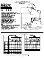
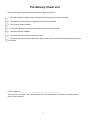
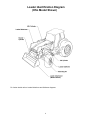
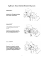
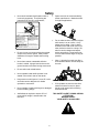
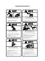
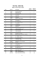
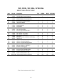
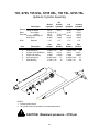
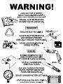
WARRANTY REGISTRATION AND POLICY
Buhler Manufacturing products are warranted fo r a period of twelve (12) months from
original date of purchase, by original purchaser, to be free fr om defects in material and
workmanship under correct, normal agricultural use and proper applications.
Buhler Manufacturing’s obligati ons under this warranty shall be limited to the repair or
exchange, at Buhler Manufacturing’s option, of any Buhler Manufacturing product or
part which proves to be defective as provided. Buhler Manufacturing reserves the right
to either inspect the product at the buyer’s location or have it returned to the factory for
inspection.
The above warranty does not extend to goods damaged or subject to accident, abuse or
misuse after shipment from Buhler Manufac turing’s factory, nor to goods altered or
repaired by anyone other than an authorized Buhler Manufacturing representative.
Buhler Manufacturing makes no Express
Warranties other than those which are
specifically described. Any descripti
on of goods, including any references and
specifications in catalogues, circulars and other written material published is for the sole
purpose of identifying goods and shall conform to such descriptions. Any sample or
model is for illustrative purposes only and does not create an Express Warranty that the
goods conform to sample or model shown.
The purchaser is solely responsible for
determining suitability of goods sold. This
warranty is expressly in lieu
of all other warranties expre ssed or implied. Buhler
Manufacturing will in no event be liable for
any incidental or consequential damages
whatsoever, nor for any sum in excess of the price received for the goods for which
liability is claimed.
WARRANTY CLAIMS:
Warranty requests must be prepared on Buhl er Manufacturing Warranty Claim Forms
with all requested information properly comple ted. Warranty Claim s must be submitted
within a thirty (30) day period from date of failure repair.
WARRANTY LABOR:
Any labor subject to warranty must be authorized by Buhler Manufacturing. The labor
rate for replacing defective parts, where app licable, will be credited at a rate determined
by the Company, Buhler Manufacturing.
IMPORTANT FACTS:
Buckets and Bucket Tines Carry No Warranty
Bent Spears Carry No Warranty
Snowblower Fan Shafts Carry No Warranty
Mower Blades Carry No Warranty
Portable Auger Parts Have Two (2) Year Warranty
Loader Parts Have Two (2) Year Warranty
PRINTED IN CANADA
795
Hydraulic Farm Loader
Operator’s Manual
Table of Contents
Section
Description
Page
Warranty Registration and Policy............................................
Table of Contents....................................................................
Introduction
and
Identification
Loader Specification Chart..................................................... 2
Torque Chart .......................................................................... 2
Pre-delivery Check List .......................................................... 3
Loader Identification Diagram ................................................ 4
Hydraulic Hose Kit Identification Diagrams............................ 5
Safety
and
Pre-use
Information
Safety ..................................................................................... 6
Important Precautions ............................................................ 7
Safety Decals ......................................................................... 8
Lubrication and Decals Location Diagram ............................. 9
Operating
Information
Assembly
and
Parts
Information
General Instructions and Information.................................... 10
Operation and Maintenance.................................................. 11
Operating Suggestions for Loading ...................................... 12
Operating Suggestions for Backfilling ................................... 13
Attaching the Loader to Your Tractor.................................... 14
Removing the Loader from Your Tractor .............................. 16
Trouble Shooting................................................................... 18
General Notes and Instructions ............................................ 19
TSL General Notes and Instructions..................................... 20
Sub-frame Diagram............................................................... 22
TSL Mainframe Diagram ....................................................... 24
Mainframe Diagram……………………………………………...26
Hydraulic Plumbing Diagram ................................................ 28
HSL Hydraulic Plumbing Diagram ........................................ 30
TSL Hydraulic Plumbing Diagram......................................... 32
Hydraulic Cylinder Assembly ................................................ 34
PLEASE READ AND UNDERSTAND THIS MANUAL
BEFORE OPERATING LOADER
Pre-delivery Check List
Before delivering this equipment please complete the following check list.
1. The loader has been installed using the appropriate mounting kit for the tractor and loader.
2. The hydraulic system installed is appropriate for the tractor and loader
3. The loader is properly installed.
4. All bolts are tightened to the torque specifications shown in the torque chart.
5. All safety decals are readable.
6. The loader has been tested and operates properly.
7. The operator’s manual has been delivered to the owner who has been instructed on the safe and proper use
of the loader.
Dealer’s Signature_________________________________________________
This check list is to remain in this Owner’s Manual and is the responsibility of the dealer to complete it before
delivery to the customer.
3
Loader Identification Diagram
(HSL Model Shown)
For further details refer to Loader Mainframe and Subframe diagrams.
4
Hydraulic (Hose Kit) Identification Diagrams
Hose Kit “A”
Loader Powered by the tractor remotes.
Consists of four hoses leading from loader
tubing to tractor remote couplers
Hose Kit “B”
Loader operated by an external OC or CC
valve that is powered from the tractor
remotes
Consists of 4 hoses leading from loader
tubing to external mounted valve and 2
hoses from valve to tractor couplers. Use
the valve type shown with hose kit “B”.
Hose Kit “C”
Loader operated by an external valve that is
plumbed into the tractor hydraulic system.
Consists of 4 hoses leading from loader
tubing to external mounted valve plus the
necessary fittings, hoses and adapter blocks
(if necessary) to tap into tractor hydraulic
system. Use valve type shown with hose kit
“C”.
5
Safety
•
Never work beneath raised loader unless it
is securely supported. The following are
instructions for the Lift Lock Supports;
•
Space rear tires as recommended by
tractor manufacturer. Maximize width
for high lift applications.
•
Do not raise bucket to extreme heights
while tractor is on an incline. Carry
loader low for safety. Note in above
illustration how load center moves out
when bucket is raised on a slope. Be
alert for terrain changes and adjust
bucket accordingly. Keep bucket low,
no more than one foot high, as long as
possible.
•
Note: A pivoting front axle acts like a
three-wheeled tractor until the stops hit
the axle.
•
If lift cylinders are used to raise front
wheels of tractor for service, place
blocks under tractor before working
around front end.
Lift Lock
Support
Clevis
Lift Cylinder Shaft
LIFT LOCK INSTRUCTIONS
TO ENGAGE SUPPORTS:
TO DISENGAGE SUPPORTS:
1. RAISE LOADER PAST LEVEL
POSITION
2. SECURE SUPPORTS INTO
POSITION ON THE CLEVIS AND
CYLINDER SHAFT.
3. SLOWLY LOWER FULL WEIGHT OF
LOADER ONTO SUPPORTS.
1. RAISE LOADER OFF LIFT LOCK
SUPPORTS.
2. SWING LOCK SUPPORTS UP INTO
STORAGE POSITION.
IMPORTANT:
-THE BUCKET MUST BE EMPTY
-ALWAYS USE BOTH SUPPORTS
-DO NOT USE WHEN TRACTOR IS MOVING.
-DO NOT STORE LIFT LOCK SUPPORTS OTHER THAN WHERE INDICATED.
-REPLACE IMMEDIATELY IF DAMAGED.
•
Do not pivot or turn tractor with bucket raised,
except at a minimum speed. Always make
allowance for length of loader when making
turns.
•
Never leave tractor unattended while the
bucket is raided. Always lower bucket to the
ground and shut off before leaving tractor seat.
•
Do not walk under raised bucket.
•
Never operate loader while operator is not
seated in the driver’s seat on the tractor.
•
Keep tractor on solid ground. Loose fill, rocks
and holes can be dangerous for loader
operation or movement.
•
Never operate a loader with frayed or damaged
hoses or leaking fittings.
•
Add ballast as required to ensure 25% of
gross vehicle weight is transferred to the
rear axle.
THIS SAFETY ALERT SYMBOL MEANS:
ATTENTION!
BECOME ALERT!
YOUR SAFETY IS INVOLVED!
6
Important Precautions
FALLING HAZARD
ELECTROCUTION HAZARD
To prevent serious injury or death:
To prevent serious injury or death:
Do not lift, carry or allow anyone to ride on or work from
any portion of loader.
Stay away from power lines and cables.
Electrocution can occur with or without direct
contact.
CRUSHING HAZARD
HIGH PRESSURE FLUID
To prevent serious injury of death:
To prevent serious injury or death:
Do not handle round bales or other shiftable objects
unless loader is equipped with an attachment designed
for this purpose.
Do not handle loose loads that are not secured.
Do not lift load higher than necessary.
Relieve pressure on system before repairing or adjusting
or disconnecting.
Wear proper hand and eye protection when searching
for leaks. Use wood or cardboard instead of hands.
Keep all components in good repair.
If hydraulic fluid penetrates skin, obtain medical
treatment IMMEDIATELY.
ROLL-OVER HAZARD
To prevent serious injury or death:
CRUSHING HAZARD
To prevent serious injury or death:
Move and turn tractor at low speed.
Carry load no higher than necessary to clear the ground
when transporting.
Add wheel ballast or rear weight for stability.
Move wheels to widest possible settings to increase
stability.
It is recommended the tractor be equipped with a rollover
protective structure (ROPS).
Do not allow bystanders in loader work area.
Lower loader to the ground before leaving seat.
Do not walk or work under raised loader. For servicing,
refer to operator's manual.
Read and understand operator's manual before operating
loader.
7
Safety Decals
These decals are located as shown on the Decal Location diagram and the Sub-Frame Assembly
diagram.
WARNING
OVERHEAD HAZARD
STAY AWAY FROM UNDER LIFT
ARMS AND BUCKET
To prevent serious injury or death:
1. Do not stand or work under raised loader, unless supported.
2. Support bucket and lift arms before working under loader.
3. Lower loader to the ground before leaving seat.
CAUTION
1. Read Operator's Manual before operating.
2. Move and turn tractor at low speed.
3. Carry loader arms at a low position during transport.
4. Lower loader arms, stop engine and lock brakes before
leaving operator seat.
5. Do not stand or work under raised loader, unless properly
supported.
6. Add recommended wheel ballast or rear weight for stability.
7. Move wheels to widest recommended settings to increase
stability.
8. Do not handle large round bales or other shiftable objects
unless loader is equipped with a grapple fork.
9. Do not use loader to move or carry people.
10. Stay away from power lines. Electrocution can occur
without direct contact.
11. Review safety instructions annually.
8
General Instructions and Information
As with any piece of equipment, the care with which your loader is operated and maintained
will greatly affect it’s life and the safety of the people using it.
1. Keep all pivots well lubricated for longer bushing life. Inspect every 500 hours of operation
for wear.
2. Periodically check all bolts for tightness. If any bolt is damaged, replace it with a bolt of
equivalent grade or strength.
3. Follow the recommendations of the tractor manufacturer in regards to the quantity of oil used.
4. Check oil level frequently to ensure the system is full.
5. When making an oil check, be sure lift cylinders are retracted.
6. Before operating the loader, particularly if the loader is left standing for any length of time,
check the hydraulic system and oil level.
7. When installing hydraulics, follow the circuit carefully. See hydraulic hook-up section and
make sure the hoses do not contact any hot manifolds or sharp edges on tractor. After
assembly, raise the loader slowly and check to make sure that the hoses do not bind in all
positions.
CAUTION
The pressure of the relief and open center valves is set at the factory. Do not tamper with the
setting, serious injury to the operator or damage to the loader or tractor hydraulics may occur.
Warranty will be void if the loader is operated above recommended pressure.
9. When servicing any hydraulic components, care must be taken to prevent any foreign matter
from entering the system.
10. Do not neglect oil leaks. Leaks affect loader operation, are dangerous and can result in
personal injury or damage to the hydraulic system.
11. Never leave the cylinder shafts exposed when loader is not in use.
12. Worn or damaged components should be replace as soon as possible with only the
manufacturer’s recommended component or equivalent.
10
Operation and Maintenance
GENERAL
Refer to tractor Operator’s Manual for Operating
information on the tractor’s hydraulic system.
Hydraulic systems using aux iliary valves should have
them located for easy reach from the tractor seat.
Hoses should be connected in such a
manner that
pushing forward on valve handles lowers the boom or
dumps the bucket.
LOWER
BOOM
DUMP
BUCKET
CAUTION: Always connect boom hoses to float
section.
Weight added to rear of tractor provides better traction
and an easier, more efficient loader operation. Extra
weight, along with widening the rear wheels, reduces
the risk of roll-over.
LOWER
BOOM
DUMP
BUCKET
WARNING
The smaller the tractor is, the easier it will roll. We
recommend that weight be added to rear tires with
liquid or by the
installation of rear wheel weights.
Where additional weight is required, a counterweight
box can be fabricated for tractors with three-point
hitches.
Extra weight can also be added by the use of a heavy
implement mounted to the three-point hitch.
A roll-over protective structure is also recommended.
11
In cold weather, operate the tractor’s engine at idle
speed until the hydraulic fluid is warmed
up. High
engine speed when the hydraulic fluid is cold will
cause the pump to wear prematurely.
Under normal conditions, operate the tractor’s engine
at ½ throttle. Shift the tractor into a low gear before
entering a pile of material to minimize strain on loader
arms.
Operating Suggestions for Loading
DO THIS!
When handling heavy loads, be sure to lower
lift arms slowly. This is known as feathering
the hydraulic lever. If load is lowered too fast
and stopped suddenly, excessive shock loads
are created which can damage loader or
tractor.
NOT THIS!
When loading bucket, drive straight into
material. Attempting to turn tractor while
loading bucket can cause damage to both the
loader and tractor.
A straight bottom offers more resistance to lift.
Come in level:
NOTE: Bottom surface of bucket is parallel to
line on motion
To increase loading efficiency, minimize angle of
turn and length to run between pile and
spreader.
Work both levers back to direct pressure to
both cylinders.
Combined action of lift and bucket cylinders
increases loading efficiency.
Leave material which drifts over side of bucket
for final clean-up.
12
Operating Suggestions
For Backfilling
DO THIS!
Backgrade work surface with a loaded
bucket. Release all pressure on lift cylinders
so full weight of bucket is scraping ground.
Use heel of bucket.
When backfilling approach pile with a flat
bucket. Leave dirt in bucket. Dumping on
each pass wastes time.
NOT THIS!
WARNING!
DO NOT USE LOADER
AS BATTERING RAM!
SAFETY: FIRST, LAST, ALWAYS
DO NOT use bucket in dumped position for
bulldozing. This will only impose severe
shock loading on the bucket cylinders and
make it more difficult to maintain a level
grade.
13
Attaching the Loader to Your Tractor
1.
Position the tractor as centrally as possible and drive, using lowest gear possible, into the
loader frame until hoses can be connected.
2.
Couple up the hydraulic hose lines to the loader or tractor valve ensuring proper function
(see Operator and Maintenance Section)
NOTE: When mounting the loader for the first time, slowly
work the cylinders back and forth, so that most of the air is
removed. Loosen the bolts on the hooks so that they can
be moved. Also, check that the nuts in the rear of the
subframes are in line with the holes.
3.
On some tractors, the lift cylinders may have to be extended slightly,
so that the subframes can clear the front axle. Do not extend the
cylinders more than is required.
IMPORTANT! On self leveling loaders, the
bucket will dump at the same time the loader
is raised. Therefore, operate both hydraulic
levers together.
4.
Drive the tractor ahead until the subframe is past the front axle and the front hook is close
to mounting boss.
WARNING! Check front grill clearance during
installation to avoid tractor damage.
5.
Retract or extend the lift cylinders to line up the front hook with the mounting boss.
IMPORTANT!
On self leveling
loaders, the bucket will roll back at
the same time the loader is lowered.
Therefore, operate both hydraulic
levers together.
14
Attaching the Loader to Your Tractor
(Continued)
6.
When the hook is lined up, dump or roll back the bucket to lower or raise the subframe
upright to align with the mounting boot.
7.
Continue to drive the tractor forward until the subframe uprights are seated in the boot.
8.
Secure the subframe uprights with the bolts and washers. Torque to 500 ft-lbs.
IMPORTANT: When mounting for the first
time, the front hook bolts will have to be
tightened after positioning the hook
directly over the mounting boss (most
rearward position).
9.
Raise the loader and lock the support stand tubes into the up position.
NOTE: When mounting for the first time,
raise the loader slowly and check to make
sure that the hoses do not bind or become
pinched in all positions. Work the loader and
bucket up and down to work out all the air in
the hydraulics. Check and refill the tractor’s
hydraulic system.
15
Removing the Loader from Your Tractor
WARNING! When removing the loader, it must be fitted with a bucket or
other suitable attachment to give the frame stability after removal. If this is
not done, the frame will not remain standing.
IMPORTANT! Always remove the loader on firm, level ground (away from
children’s play areas and high traffic areas). This makes attaching and
removing much faster and easier. It also makes the free standing loader
more stable.
1.
Raise the loader, lower support stand tubes and lock into position
2.
Lower the loader until the stand tubes are firmly on the ground and
then dump the bucket so that it is also firmly on the ground.
There should be slight downward pressure.
3.
Loosen the bolts from the rear of the subframe boots and swing
bolt up into lock position.
16
Removing the Loader from Your Tractor
(Continued)
4.
Roll back the bucket slightly and simultaneously extend or retract
the lift cylinders to free hooks from spools. Then slowly back
up the tractor.
5.
Once the subframe is clear of the boot and the hook is clear of the mounting boss, roll
back the bucket all the way. This raises the rear uprights of the loader.
NOTE: On some mountings, the lift cylinders
must be extended more while the tractor is
backing up, so that the subframes clear the
front axle.
6.
Continue backing up until the loader is clear.
CAUTION! Be sure the hoses DO NOT get
pinched or catch on any frame members
while backing up.
7.
After the loader is clear, retract the lift cylinders to protect the shafts and disconnect the
hydraulic lines at quick couplers.
17
Trouble Shooting
PROBLEM
Loader slow and/or will not dump.
POSSlBLE CAUSE
Quick couplers leaking.
Hydraulic oil too heavy.
Oil filter plugged.
Hydraulic pump worn.
Oil line restricted or leaking.
Control valve does not shift properly.
Air in hydraulic system.
Loader chatters or vibrates when
raising and lowering.
Excessive movement at pivots
Pump noisy
Oil leaks.
Insufficient lift capacity
Cylinder leaks internally.
Faulty valve.
Air leak in pump inlet line.
Air in hydraulic system.
Oil level too low.
Worn bushings and/or pins.
Inlet line restricted or leaking.
Oil level too low.
Pump worn or damaged.
Damaged fittings or hoses.
Loose connections.
Worn or damaged O-ring wiper
seal in cylinder rod end.
Worn or damaged O-rings in valve.
Improper hydraulic pump operation.
Load is greater than boom lift capacity.
Internal boom cylinder leakage.
Improper hydraulic valve operation.
Worn control valve.
Worn cylinder piston seals.
Excessive wear on bottom oil bucket Float position not used while operating
and wear pads.
loader.
Hydraulic cylinders inoperative.
Hose from control valve improperly
connected.
Pump operating continually on closed Tractor control valve relief stuck
center tractor hydraulic system.
open.
Slow leakdown.
Loader lift and bucket tilt controls do
not work according to decal.
Valve noisy and/or hot
Tractor loads/pump squeals
Hydraulic control valve set too low.
Hoses improperly connected.
Open center control valve on closed
center tractor.
Closed center control valve on open
center tractor.
18
REMEDY
Check connections and compatibility or
replace.
Change or replace filter.
Clean or replace filter.
Repair or replace pump.
Check all hoses and tubes for leaks,
damage or restrictions. Replace damaged
or restricted hoses or tube lines.
Inspect, clean, repair or replace valve.
Cycle lift cylinders and bucket cylinders
several times to free system of air.
Replace seals.
Repair or replace valve.
Check, tighten or replace inlet line.
Cycle lift cylinders and bucket cylinders.
Add oil as required.
Replace bushings and/or pins.
Check for air leaks, restrictions or collapsed
hose. Tighten or replace hose. Clean
filter if necessary.
Add oil as required.
Repair or replace pump.
Replace damaged parts.
Tighten fittings.
Install a seal repair kit.
Install an O-ring repair kit.
Repair or replace pump.
Check loader specifications.
Replace any worn parts and install
a seal repair kit.
Repair or replace valve.
Have authorized dealer replace seals.
Have authorized dealer replace seals.
Use float position provided on valve.
Refer to plumbing diagrams.
See your tractor manual for proper
adjustment or Loader dealer for loader
valve. (3000 PSI is maximum pressure
relief setting recommended.)
Adjust valve in accordance with manual.
Refer to plumbing diagrams
and correct hose connections.
Replace relief valve with closed center plug
and plug the power beyond adapter on valve.
Install open center plug on optional valve.
Replace closed center plug with relief and
install short plug in place of power beyond
adapter.
General Notes and Instructions to the Operator
Regarding ALLIED HSL Loader Operations
1. The
hydraulic self-leveling system (HSL) utilizes two metering cylinders
which displace oil into or out of the bucket cylinders as the loader is raised
or lowered. The cylinder volumes and geometry’s are carefully matched
for each loader model to provide the correct amount of oil to keep the
bucket level after it is initially leveled.
2.
The HSL system incorporates two relief valves which are only utilized if
the bucket cylinders are at either end of the stroke. If the loader is
raised with the bucket fully dumped, oil will be bypassed at high
pressure into the lower side of the lift cylinder circuit. If the loader is
lowered with the bucket fully rolled back, oil will be bypassed at high
pressure into the raised side of the lift cylinder circuit. Note that these two
conditions are likely to occur only intermittently, and although the pump
will be forced to supply oil at a higher pressure no damage to the loader
components will occur. It is, however, recommended to avoid the above
situations and keep the bucket somewhat level while raising or lowering
the loader for smoother operation.
3.
Note that the large volume (piston side) of the leveling cylinders is
connected to the large volume of the bucket cylinders, and the small
volume (rod side) is connected between the two sets of cylinders. The
effect of this configuration is to create a breakout force “boost” if the
bucket cylinders are pressurized toward the rollback position during
breakout.
4.
The opposite effect of the above situation is that the loader will have poor
lift capacity if lifting with the bucket cylinders pressurized in the dumped
position. This is, however, a very unlikely occurrence (lifting a load with
bucket fully dumped).
5.
The cartridge style relief valves are factory set at 2,000 psi cracking
pressure and are capable of bypassing 15-20 GPM. If loader lock-up
should occur due to a low tractor relief setting, higher inlet flows or return
line restrictions, the relief valve setting may be bucket off slightly until the
lock-up condition is overcome (as described in note 2 above).
6.
CAUTION: Never utilize the leveling cylinders to raise the loader. This
could occur if the lift cylinders are placed in float while the bucket cylinders
are held pressurized in the retracted position. If the loader should rise,
pressurize the lift cylinders to lower it; otherwise a rapid drop may occur
when the bucket cylinders are extended. Note that this situation is unlikely
to occur during normal loader operation and is possible only with a lightly
loaded bucket.
19
General Notes and Instructions to the Operator
Regarding ALLIED TSL Loader Operations
1. The
true self levelling system (TSL) utilizes mechanical linkages to
maintain bucket level while raising and lowering. The pivot plate
weldment, levelling tubes and linkages have been developed to ensure
that the bucket remains at the same position throughout its range of
motion. This feature is standard with 2.50” and 3.00” diameter bucket
cylinders.
2.
The TSL system incorporates a relief and anticavitation manifold to
provide extra dump at ground and rollback at full lift height. This feature is
available on 3.00” bucket cylinders only. If the loader is raised with the
bucket fully dumped, oil from the bucket piston side will be bypassed at
high pressure to the bucket shaft side and the lift shaft side as the quick
attach contacts the dump stop. If the loader is lowered with the bucket
fully rolled back, oil from the bucket shaft side will be bypassed at high
pressure to the bucket piston side and makeup will be provided by the lift
piston side as the quick attach contact the rollback stop. Note that these
two conditions are likely to occur intermittently and although the pump will
be forced to supply oil at a higher pressure, no damage to the loader
components will occur. It is, however, recommended to avoid the above
situations and keep the bucket somewhat level while raising or lowering
the loader for smoother operation.
3.
The extra bucket stroke length allows for the bucket to be dumped to
approximately 90 degrees at ground. This allows for bucket assist when
traction is minimal. If the loader is raised from this position, the bucket will
retract as the quick attach contacts the dump stop and the circuit goes
through relief as described in note 2.
4.
Extra bucket retraction allows for the bucket to be rolled back as the
loader raises. The TSL feature maintains the bucket level, but as required
the bucket can be manually rolled back approximately 20 degrees to allow
for increased bucket capacity. If the loader is lowered from this position,
the bucket will extend as the quick attach contacts the rollback stop and
the circuit goes through relief as described in note 2.
5.
The relief valve is factory set at 3250 PSI cracking pressure and is
capable of bypassing 10-15 GPM. If loader lock-up should occur due to a
low tractor relief setting, higher inlet flows or return line restrictions, the
relief valve may be backed off slightly until the lock-up condition is
overcome (counterclockwise turn of set-screw). Contact the factory for
further instructions.
20
Notes
21
795, 795 HSL, S795, S795HSL, 795 TSL, S795 TSL
Sub Frame Parts Table
Item
1
2
1
2
1
2
1
2
3
4
5
6
7
8
9
10
11
12
13
14
15
16
17
18
19
20
21
22
23
24
25
26
27
Part No.
31411
31412
31408
31409
31423
31424
31425
31426
112751
112747
112746
112748
111423
111426
112642
113281
110887
812717
812026
812944
84127
812939
81967
81723
112730
112812
112805
112983
112982
812882
113474
24329
112615
Description
795 Sub Frame Weldment Left
795 Sub Frame Weldment Right
795 HSL Sub Frame Weldment Left
795 HSL Sub Frame Weldment Right
795 S Sub Frame Weldment Left
795 S Sub Frame Weldment Right
S795HSL Sub Frame Weldment Left
S795HSL Sub Frame Weldment Right
Hook Weldment
Plate Clamp
Spacer Block
Shim
Cross Member Weldment
Tube Cross Member
Shaft Pivot 1.75 DIA X 5.50 Long
Bolt Retainer Weldment
Loader Lift Lock Weldment
Grommet 0.375 ID X 1.00 OD X .13
Bolt Hex 0.313nc X 1.00 gr5 pl
Bolt Car. 0.625nc X 3.00 gr5 pl
Bolt Car. 0.625nc X 3.50 gr5 pl
Bolt Hex 0.875nc X 10.00 gr8 pl
Nut Lock (nylon) 0.625nc grB pl
Washer Lock 0.875 pl
Washer Boot
*Decal General Caution
*Decal - 795 X 1.40
*Decal - Warning Overhead Hazard
*Decal - Lift Lock Instruction
Bolt Car. 0.625nc X 2.50 gr5 pl
*Decal - Cross Member Caution
Mounting Wrench (for 0.875 bolt)
*Decal - S X 1.40
*Part of decal replacement kit X9942
23
Regular
Quantity
1
1
2
2
4
2
1
1
2
2
2
2
2
8
2
2
14
2
2
2
2
2
2
4
2
-
HSL/TSL
S795HSL/TSL
Quantity S Quantity
Quantity
1
1
1
1
1
1
2
2
2
2
2
2
4
4
4
2
2
2
1
1
1
1
1
1
2
2
2
2
2
2
2
2
2
2
2
2
2
2
2
8
8
8
2
2
2
2
2
2
14
14
14
2
2
2
2
2
2
2
2
2
2
2
2
2
2
2
2
2
2
4
4
4
2
2
2
1 (TSL)
1 (TSL)
1
-
795 TSL, S795 TSL
Main Frame Parts Table
Item
1
1
2
3
4
5
6
7
8
9
10
11
12
13
14
15
16
17
18
19
20
21
22
23
24
25
26
27
28
29
30
31
32
33
34
35
36
37
38
39
40
41
42
43
44
45
46
47
48
Part No.
24731
24739
24717
24716
112798
108827
114296
114303
113690
110907
12779
114170
112954
112955
112800
114194
24242
24708
24314
114252
81581
81669
81592
81344
81967
113691
81570
113570
113766
114104
113697
113154
114119
114120
81966
84583
FNH114039
FNH114040
114097
114101
113998
113995
813228
81637
813356
114132
813358
113488
52281-000
Description
795 TSL Mainframe
S795 TSL Mainframe
Quick Attach Left
Quick Attach Right
Cross Tube
Pin Weldment
Stand Tube
Stand foot
Link Spacer
Stand Pin 0.625 diameter
Hair Pin Clip
Levelling Rod
Pin 1.25 X 6.75 LG
Pin 1.25 DIA X 5.00 LG
Pin 1.25 DIA X 6.13 LG
Levelling Tube
Cross Tube Cover
Cylinder Bucket
Cylinder Lift
Pin 1.25 dia. X 6.75 lg
Hex Bolt 0.375 DIA X 2.5 LG
Hex Bolt 0.625 DIA X 3.5
Hex Nut 0.375 DIA
Locknut 0.375 DIA
Locknut 0.625 DIA
Bushing 1.25 I.D. X 1.63 O.D x 0.75'' lg
Flat Washer 0.375 DIA
Bushing 1.25 I.D. X 1.63 O.D. x 1.88'' lg
Bushing 1.25 I.D. x 1.50 O.D. x 1.38'' lg
Pin 1.25 DIA X 7.48
Pin 1.25 DIA X 8.63 LG
Pin 1.25 DIA X 7.63 LG
Link Weldment Left
Link Weldment Right
Locknut 0.50 DIA
Grease Fitting 1/8 NPT Straight
Bolt Plate
Rod Guide
Link Assembly 11.25
Pivot Plate Left
Pivot Plate Right
Pin 1.25 DIA X 7.13 LG
1/2" Wing nut (pl)
1/2" Lock washer (Pl)
Decal - Buhler Allied X 1.75
Decal - TSL X 1.75
Decal - True Self Leveling
Decal - Quick Attach Instruction
Bright Orange Scotchcal #72368
25
795 TSL
Quantity
1
1
1
1
2
2
2
2
2
4
1
2
2
2
2
1
2
2
4
32
4
4
41
4
8
4
4
20
4
4
2
2
2
2
2
1
1
4
1
1
2
2
2
2
2
2
2
10ft
S795 TSL
Quantity
1
1
1
1
2
2
2
2
2
4
1
2
2
2
2
1
2
2
4
32
4
4
41
4
8
4
4
20
4
4
2
2
2
2
2
1
1
4
1
1
2
2
2
2
2
2
2
10ft
795, S795, 795 HSL, S795 HSL
Main Frame Parts Table
Item
1
1
1
1
2
3
4
5
6
7
8
9
10
11
12
13
14
15
16
17
18
19
20
21
22
23
24
25
26
27
28
29
Part No.
31596
31595
31597
31600
24296
24297
112798
108827
111231
111232
24329
110907
12779
111441
112954
112955
112800
113766
24242
24309
24314
24319
81581
81669
81592
81344
81967
81570
23842
813356
52281-000
113488
Description
795 Main Frame Weldment
795 HSL Main Frame Weldment
S795 Main Frame Weldment
S795 HSL Main Frame Weldment
Quick Attach Weldment Left
Quick Attach Weldment Right
Tube Cross Qtach
Pin Weldment
Stand Weldment
Strap Stand
Wrench Mounting
Pin 0.625 Dia. Stand
Hair Pin Clip #9 Western Wire
Levelling Rod
Pin 1.25 Dia. x 6.75 Long
Pin 1.25 Dia. x 5.00 Long
Pin Qtach
Bushing 1.25 ID x 1.50 OD x 1.375 Long
Tube Cover
3.0 Dia. x 20.75 Bucket Cylinder
3.0 Dia. x 30.00 Lift Cylinder
3.5 Dia. x 12.00 Leveling Cylinder
Bolt Hex 0.375nc x 2.50 gr5 pl
Bolt Hex 0.625nc x 3.50 gr5 pl
Nut Hex 0.375nc gr2 pl
Nut Lock (nylon) 0.375nc grB pl
Nut Lock (nylon) 0.625nc grB pl
Washer Flat Std. 0.375 hs pl
*Decal - Hyd. Self Level x 0.75
*Decal - Buhler Allied x 1.75
*Bright Orange Scotchcal #72368
*Decal - Quick Attach Instruction
*Part of decal replacement kit X 9942
27
795
1
1
1
1
2
2
2
1
2
5
1
4
4
4
8
1
2
2
16
4
4
20
6
4
2
12ft
2
795HSL
1
1
1
1
2
2
2
1
2
5
1
6
6
4
8
1
2
2
2
20
4
4
24
6
4
2
2
12ft
2
S795
1
1
1
1
2
2
2
1
2
5
1
6
6
4
8
1
2
2
16
4
4
20
6
4
2
12ft
2
S795 HSL
1
1
1
1
2
2
2
1
2
5
1
6
6
4
8
1
2
2
2
20
4
4
24
6
4
2
2
12ft
2
795, S795
Hydraulic Plumbing Diagram
28
795, S795
Plumbing Parts Table
Item
1
2
3
4
5
6
7
8
9
10
11
12
13
14
15
16
17
18
Part No.
24309
24314
811572
811471
811466
812947
112833
112834
112937
112835
112836
112837
812128
811414
812069
11362
81592
81344
Description
3.0 Dia. x 20.75 Cyl. Assy. Bucket
3.0 Dia. x 30.00 Cyl. Assy. Lift
3/8 x 15" Hose 3/4 MORB x 3/4 SWFJIC
3/8 x 20" Hose 3/4 MORB x 3/4 SWFJIC
3/8 x 24" Hose 3/4 MORB x 3/4 SWFJIC
3/8 x 22" Hose 3/4 SWFJIC x 3/4 SWFJIC
Tubing - Lift Cyl. Bottom Raise
Tubing - Lift Cyl. Top Drop
Tubing - Lift Cyl. Common (31.0")
Tubing - Bucket Cyl. Bottom Rollbk
Tubing - Bucket Cyl. Top Dump
Tubing - Bucket Cyl. Cross Tube
Elbow 90 3/4 MJIC x 3/4 MJIC
Elbow 90 3/4 MORB x 3/4 MJIC
Tee 3/4 MJIC
Clip Pipe Std.
Nut Hex 0.375nc gr2 pl
Nut Lock (Nylon) 0.375nc grB pl
29
Qty.
2
2
2
2
2
2
1
1
2
1
1
2
4
2
4
9
4
5
795 HSL, S795 HSL
Hydraulic Plumbing Diagram
30
795 HSL, S795 HSL
Hydraulic Plumbing Diagram
Item
1
2
3
4
5
6
7
8
9
10
11
12
13
14
15
16
17
18
19
20
21
22
23
24
25
Part No.
24319
24309
24314
811754
811572
811471
811466
812947
811434
112837
112937
112833
112834
112835
112836
112831
112832
23875
811414
812069
812786
812828
11362
81592
81344
Description
3.5 Dia. x 12.00 Cyl. Assy. Level
3.0 Dia. X 20.75 Cyl. Assy Bucket
3.0 Dia. X 30.00 cyl. Assy Lift
3/8 x 18 Hose 3/4 MORB x 3/4 SWFJIC
3/8 x 15 Hose 3/4 MORB x 3/4 SWFJIC
3/8 x 20 Hose 3/4 MORB x 3/4 SWFJIC
3/8 x 24 Hose 3/4 MORB x 3/4 SWFJIC
3/8 x 22 Hose 3/4 SWFJIC x 3/4 SWFJIC
3/8 x 30 Hose 3/4 MORB x 3/4 SWFJIC
Tubing - Bucket Cyl. Cross Tube
Tubing - Lift Cyl. Top Drop Common
Tubing - Lift Cyl. Bottom Raise
Tubing - Lift Cyl. Top Drop
Tubing - Bucket Cyl. Bottom Rollback
Tubing - Bucket Cyl. Top Dump
Tubing - Bucket Cyl. Bottom Ext HSL
Tubing - Bucket Cyl. Top Ext HSL
Valve Relief Assy
Elbow 90 3/4 MORB x 3/4 MJIC
Tee 3/4 MJIC
Tee 3/4 MJIC x 3/4 SWFJIC
Tee 3/4 MORB 3/4 MJIC x 3/4 MJIC
Clip Pipe Std.
Nut Hex 0.375nc gr2 pl
Nut Lock (Nylon) 0.375nc grB pl
31
Qty.
2
2
2
1
2
2
4
4
1
2
2
1
1
1
1
1
1
2
4
8
2
2
11
4
7
795 TSL, S795 TSL
Plumbing Parts Table
Item
1
2
3
4
5
6
7
8
9
10
11
12
13
14
15
16
17
18
19
20
21
22
23
24
25
26
Part No.
24314
24708
812069
886897
811414
812128
11362
113031
114233
114234
114235
114236
114328
112837
811471
811424
114605
811434
114237
812697
812696
115260
115730
25253
812052
81922
Description
3.0 DIA x 30.00 Cylinder Assembly Lift
3.0 DIA x 22.00 Cylinder Assembly Bucket
Tee 3/4-16MJIC X 3/4-16 MJIC
Adaptor Str 7/8 Morb x 3/4 MIJC
Elbow 90º 3/4-16 MORB to 3/4 MJIC
Elbow 90º 3/4 MJIC x 3/4 MJIC
Pipe Clip
Tubing Ext. Lift Cyl 23.0"
Tubing Lift Cyl. (Bottom, Raise)
Tubing Lift Cyl. Right (Top, Drop)
Tubing Bucket Cyl. (Bottom, Dump)
Tubing Bucket Cyl. (Top, Rollback)
Tubing Lift Cyl. Left (Bottom, Raise)
Tubing Cross Tube
Hose 3/8 X 20 3/4-16 MORB X 3/4-16 SWJIC
Hose 3/8 X 30 3/4-16 SWFJIC X 3/4-16 SWFJIC
Hose 3/8 X 24 3/4-16 MORB X 3/4-16 SWFJIC
Hose 3/8 X 30 3/4-16 MORB X 3/4-16 SWFJIC
Tubing Lift Cylinder Left (Top, Drop)
Hose 3/8 x 24 3/4 Swfjic x 3/4 Swfjic
Hose 3/8 x 18 3/4 Swfjic x 3/4 Swfjic
Hose 3/8 x 15 3/4 Swfjic x 3/4 Swfjic
Hose 3/8 x 20 3/4 Swfjic x 3/4 Swfjic
TSL Manifold
Bolt Hex 0.250nc x 3.00 gr5 pl
Nut Lock (Nylon) 0.25nc grbpl
33
Quantity
2
2
8
4
2
2
9
2
1
1
1
1
1
2
2
2
2
2
1
1
1
1
1
1
2
2
795, S795, 795 HSL, S795 HSL, 795 TSL, S795 TSL
Hydraulic Cylinder Assembly
Description
Diamete
r
Length of Stroke
Retra
cted Length
Extended
Length
Cylinder Assembly No.
Seal Kit No.
Shaft
Diameter
Item
1
2
3
4
5
6
7
Description
Head Plate
Shaft Weldment
Cylinder Tube Weldment
Piston Half (wide)
Piston Half (narrow)
Self-Locking Nut
Shaft Bushing
TSL
Bucket
Bucket
Lift
Cylinders Cylinders
Cylinders
3.00"
3.00”
3.00"
20.75"
22.00”
30.00"
35.38" 51.75”
41.50"
58.13"
73.75” 71.50"
24309
24708
24314
X1656
X1424
X1424
1.50"
1.75”
1.75"
Part
Part
Number
Number
24656 2460
6
112865 1139
28
24409
24713
112862
112862
112863
112863
810457 8104
57
113766 1135
78
Leveling
Cylinders
3.50"
12.00"
22.00"
34.00"
24319
X1655
1.75"
Part
Part
Number
Number
24606 2465
5
112873 1129
34
24313
24317
112882
112659
112883
112941
810457 8104
57
113766 1137
66
NOTES:
1. Bucket cylinder shown
2. All cylinder seals are contained in corresponding seal kit.
CAUTION: Maximum pressure – 2750 psi
34
DIVISION LOCATIONS
U.S. WAREHOUSES
Allied Division
1201 Regent Ave. W.
Box 1003
Winnipeg, MB R2C 3B2
Ph.: (204) 661-8711
Fax: (204) 654-2503
AR, West Memphis
(870) 732-3132
NC, Dunn
(910) 892-8500
GA, Stone Mountain
(770) 908-9439
NC, Statesville
(704) 873-0531
IA, Atlantic
(712) 243-5520
ND, Bismarck
(701) 223-1886
Farm King Division
301 Mountain Street S.
Morden, MB R6M 1X7
Ph.: (204) 822-4467
Fax: (204) 822-6348
IA, Lakeview
(712) 657-8585
ND, Fargo
(701) 282-7003
ID, Meridian
(208) 887-6006
NY, Oneida
(315) 363-3390
IL, Hooppole
(815) 948-2591
NY, Syracuse
(315) 463-5276
IL, LeRoy
(309) 962-8414
OH, Youngstown
(330) 793-0862
IN, Clarksville
(812) 284-3376
OR, Portland
(503) 234-0378
IN, Crawfordsville
(317) 362-4495
SD, Huron
(605) 352-8616
KS, Wichita
(765) 265-9577
TX, Houston
(713) 928-2632
MN, Lakeville
(952) 469-5267
UT, Salt Lake City
(801) 972-4321
MT, Billings
(406) 248-7771
WI, Portage
(608) 742-1370
Inland Division
675 Washington Ave.
Winnipeg, MB R2K 1M4
Ph: (204) 667-7854
Fax: (204) 669-2599
B.I.I. Division
rd
1330 43 Street N.W.
Fargo, ND 58102
Ph: (701) 282-7014
Fax: (701) 282-5865
CANADIAN WAREHOUSES
B.C., Abbotsford
(604) 864-2665
NE,
AB, Edmonton
(403) 962-6991
Gothenburg
(308) 537-7175
OFFSHORE WAREHOUSES
SK, Regina
(306) 781-2300
Burando Hill
Katanning
W. Australia
011-618-98-214422
ON, Woodstock
(519) 539-0435
ON, Jasper
(613) 283-1758
QC, Dorion
(450) 455-4840
011-52
Chihuahua, Mexico
-158-90306
Buhler Manufacturing “a partnership”
1201 Regent Ave. W.
Winnipeg, MB.
R2C 3B2
Ph.: (204) 661-8711
Fax: (204) 654-2503
www.buhler.com
Printed in Canada
John Kerr Equipment Ltd.
Wilcoxholm Farm
Linlithgow, W. Lothian
Scotland
011-441-506-842280
Skovde, Sweden
011-46-500-452651
Naestved, Denmark
011-45-557-29511