1
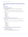
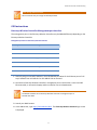
VIEW CERTIFIED CONFIGURATION GUIDE
October 2012 | 1725-36166-001 Rev C
SpectraLink® 8020/8030 and 8400 Series Wireless Telephones
with
Enterasys Networks®
Enterasys C20, C25, C4110, C5110, C5210, V2110
with AP 3605, 3610, 3620, 3630, 3640
VIEW Configuration Guide: Enterasys Networks
Trademarks
©2012, Polycom, Inc. All rights reserved.
POLYCOM®, the Polycom "Triangles" logo and the names and marks associated with Polycom products are
trademarks and/or service marks of Polycom, Inc. and are registered and/or common law marks in the United States
and various other countries. All other trademarks are property of their respective owners. No portion hereof may be
reproduced or transmitted in any form or by any means, for any purpose other than the recipient's personal use,
without the express written permission of Polycom.
Disclaimer
While Polycom uses reasonable efforts to include accurate and up-to-date information in this document, Polycom
makes no warranties or representations as to its accuracy. Polycom assumes no liability or responsibility for any
typographical or other errors or omissions in the content of this document.
Limitation of Liability
Polycom and/or its respective suppliers make no representations about the suitability of the information contained in
this document for any purpose. Information is provided "as is" without warranty of any kind and is subject to change
without notice. The entire risk arising out of its use remains with the recipient. In no event shall Polycom and/or its
respective suppliers be liable for any direct, consequential, incidental, special, punitive or other damages whatsoever
(including without limitation, damages for loss of business profits, business interruption, or loss of business
information), even if Polycom has been advised of the possibility of such damages.
Customer Feedback
We are striving to improve the quality of our documentation and we appreciate your feedback. Email your opinions
and comments to [email protected].
Visit support.polycom.com for software downloads, product documents, product licenses, troubleshooting tips,
service requests, and more.
2
Contents
Introduction .....................................................................................................5
Certified Product Summary .................................................................................................................. 5
Known Limitations ................................................................................................................................ 6
Polycom References.............................................................................................................................. 6
Product Support .................................................................................................................................... 6
Chapter 1: Network Connection and Provisioning ............................................ 9
Overview ............................................................................................................................................... 9
Network Topology ................................................................................................................................ 9
Accessing the Enterasys Wireless Controller for the First Time ......................................................... 10
CLI Instructions ................................................................................................................................ 10
Enterasys Wireless Controller C20 .............................................................................................. 10
Enterasys Wireless Controller, C25, C4100, C5110, C5210......................................................... 10
To access all Enterasys Wireless Controllers using a terminal program: .................................... 10
GUI Instructions............................................................................................................................... 11
Enterasys Wireless Controller Management port interface ....................................................... 11
Reset to Factory Defaults.................................................................................................................... 12
CLI Instructions ................................................................................................................................ 12
GUI Instructions............................................................................................................................... 13
Upgrading the Enterasys Wireless Convergence Software ................................................................ 14
Provisioning Enterasys Wireless Controller ........................................................................................ 15
Defining the Topology and Setting Up for PTT Operation .............................................................. 15
For “Physical” Topology Mode .................................................................................................... 16
For “Routed” Topology Mode ..................................................................................................... 16
For “Bridge Traffic Locally At AP Topology” Mode ..................................................................... 17
For “Bridge Traffic Locally At HWC Topology” Mode.................................................................. 18
Default Gateway ............................................................................................................................. 19
Enterasys Wireless AP Discovery ..................................................................................................... 20
Chapter 2: Configuration for Wi-Fi Standard QoS ........................................... 23
Defining RADIUS Servers ..................................................................................................................... 23
Defining Admission Control Thresholds.............................................................................................. 25
Defining Classes of Service.................................................................................................................. 26
Defining a Class of Service Policy .................................................................................................... 27
Create a Custom Class of Service ................................................................................................ 28
Create a Second Class of Service................................................................................................. 30
3
VIEW Configuration Guide: Enterasys Networks
Define Policy for Custom Classes of Service ............................................................................... 32
Setting up WLAN Services ................................................................................................................... 34
Setting up Security .......................................................................................................................... 34
Setting up Privacy for WPA2-Enterprise ..................................................................................... 34
Setting up Privacy for WPA2-PSK ................................................................................................ 35
Setting up Privacy for None ........................................................................................................ 36
Setting up Authentication for WPA2-Enterprise......................................................................... 37
Setting up Authentication for WPA-PSK ..................................................................................... 38
Setting up Quality of Service (QoS) for the WLAN Services ............................................................. 39
Setting up an Idle Timeout .............................................................................................................. 42
Setting up Radio Properties ................................................................................................................ 43
Defining 80xx and 8400 VNS (subnets) ............................................................................................... 47
4
Introduction
Polycom’s Voice Interoperability for Enterprise Wireless (VIEW) Certification Program is designed to
ensure interoperability and high performance between SpectraLink 8440/8450/8452 and 8020/8030
Wireless Telephones and WLAN infrastructure products.
The products listed below have been thoroughly tested in Polycom’s lab and have passed VIEW
Certification. This guide describes the configuration of the Enterasys C20C25, C4110, C5110, C 5210,
V2110 and the Enterasys AP 3605, 3610, 3620, 3630, 3640 with SpectraLink 8020/8030 and
8440/8450/8452 Wireless Telephones.
Certified Product Summary
Manufacturer:
Enterasys Networks: www.enterasys.com
Certified products:
Controllers:
C20
C25
C4110
C5110
C5210
V2110
AP Radio(s):
2.4 GHz (802.11b/g/n), 5 GHz (802.11a/n)
Security:
None, WEP, WPA-PSK, WPA2-PSK, WPA2-Enterprise (EAP-FAST and
PEAPv0/MSCHAPv2) with OKC (Opportunistic Key-Caching)
QoS:
Wi-Fi Standard for SpectraLink 8440/8450/8452 and 8020/8030
AP and WLC software
version tested:
8.11.06.0002
Network topology:
Bridge Traffic Locally at HWC
Bridge Traffic Locally at AP
Routed**
Handset* models tested:
SpectraLink 8440/8450/8452 Wireless Telephone
Handset radio mode:
802.11b
802.11b/g
802.11bgn
802.11a & 802.11an
Meets VIEW minimum call
capacity per AP:
8 calls
8 calls
8 calls
10 calls
Handset models tested:
SpectraLink 8020/8030 Wireless Telephone
Handset radio mode:
802.11b & b/g mixed. 802.11 g only
802.11a
Meets VIEW minimum call
capacity per AP:
6 calls
8 calls
APs:
3605
3610
3620
3630
3640
*SpectraLink handset models and their OEM derivates are verified compatible with the WLAN hardware
and software identified in the table. Throughout the remainder of this document they will be referred to
5
VIEW Configuration Guide: Enterasys Networks
collectively as “SpectraLink Wireless Telephones”, “phones” or “handsets”. The 8440, 8450 (with 1D bar
code reader), and 8452 (with 1D and 2D bar code reader) handsets will be referred to collectively as the
8400 handsets.
** Routed network topology is only recommended with single controller deployment. If multiple
controllers are present then the Mobility feature must be configured.
Known Limitations
• A-MPDU aggregation in 11n mode is not recommended on the radio supporting the handsets. AMSDU is compatible.
• Only “Fit” mode (not standalone) is supported with the handsets. The AP 3630/3640 models need
to be converted to “Fit” mode as they are in standalone mode by default. See the Enterasys
Wireless Convergence Software User Guide Version 8.11.xx for details.
• The Admission Control Thresholds algorithm employed by Enterasys Wireless Controllers will
prevent accepting additional calls once the total network traffic exceeds the percentage defined,
regardless of class of the traffic.
Polycom References
For the SpectraLink 8020/8030 Wireless Telephones, please refer Best Practices Guide for Deploying
SpectraLink 8020/8030 Wireless Telephones This white paper covers the security, coverage, capacity
and QoS considerations necessary for ensuring excellent voice quality with enterprise Wi-Fi networks.
For the SpectraLink 8400 Series Wireless Telephones, please refer to Best Practices Guide for Deploying
Polycom SpectraLink 8400 Series Wireless Telephones for detailed information on wireless LAN layout,
network infrastructure, QoS, security and subnets.
These two white papers identify issues and solutions based on SpectraLink’s extensive experience in
enterprise-class Wi-Fi telephony. It provides recommendations for ensuring that a network environment
is adequately optimized for use with SpectraLink Wireless Telephones.
The Polycom UC Software Administrators’ Guide provides a comprehensive list of every parameter
available on SpectraLink 8400 Series Wireless Telephones.
Product Support
For additional support, contact Enterasys Networks using one of the following methods:
• World Wide Web http://www.enterasys.com/support
• Phone 1-800-872-8440 (toll-free in U.S. and Canada)
or 1-978-684-1000
6
Introduction
• For the Enterasys Networks Support toll-free number in your country:
http://www.enterasys.com/support
• Internet mail [email protected]
For the most effective response from Enterasys Network Support, please type [Enterasys Wireless
Convergence Software] in the subject line.
7
Chapter 1: Network Connection and
Provisioning
Overview
SpectraLink 8020/8030 phones can be configured with Wi-Fi Standard QoS from the WLAN Settings
menu using the Custom selection.
SpectraLink 8400 phones only support Wi-Fi Standard QoS.
Network Topology
Note: Example configuration shown
This configuration is not applicable to all customer environments.
9
VIEW Configuration Guide: Enterasys Networks
Accessing the Enterasys Wireless Controller for the First
Time
CLI Instructions
Enterasys Wireless Controller C20
1 Download the CP210x VCP driver that is specific to your Operating System (OS) from
www.silabs.com.
2 Connect your laptop to the Enterasys Wireless Controller C20 via USB A/B Device Cable.
1 Using a terminal program of choice, configure the following settings for the appropriate COM
device:
○ Speed – 115200
○ Databits – 8
○ Parity – None
○ Stop Bits – 1
○ Flow Control – None
Enterasys Wireless Controller, C25, C4110, C5110, C5210
1 Connect your laptop to the Enterasys Wireless Controller via Null Modem DB9 F-F (Female to
Female) cable.
2 Using a terminal program of choice, configure the following settings for the appropriate COM
device:
○ • Speed – 115200
○ • Databits – 8
○ • Parity – None
○ • Stop Bits – 1
○ • Flow Control – None
To access all Enterasys Wireless Controllers using a terminal program:
1 At the login: prompt, type admin.
2 At the Password: prompt, type abc123.
3 Press Enter. The Enterasys Wireless Convergence OS banner is displayed.
10
Network Connection and Provisioning
Note: Change default password.
We recommend that you change the default password.
GUI Instructions
Enterasys Wireless Controller Management port interface
The management port on the Enterasys Wireless Controller may be labeled differently depending on the
Enterasys Wireless Controller.
Management port label on the Enterasys Wireless Controller
Enterasys Wireless Controller
Management Port Label
C5110
Gb 1
C4110
Gb 1
C5210
(Gigabit Ethernet) port1
C20
Admin
C25
Management
V2110
eth0 (as defined by VM installation)
1 Statically assign an unused IP address in the 192.168.10.0/24 subnet for the Ethernet port of a PC.
Any IP address from 192.168.10.2 to 192.168.10.254 can be used.
2 Connect the Enterasys Wireless Controller’s management port to the PC with a cross-over RJ45
Ethernet cable, or connect the laptop and the controller into an isolated switch.
Note: Default Management Port Address
The default IP address of the Enterasys Wireless Controller’s management port is
192.168.10.1:5825.
3 Launch your Web browser.
4 In the address bar, type https://192.168.10.1:5825. The Enterasys Wireless Assistant login screen
is displayed.
11
VIEW Configuration Guide: Enterasys Networks
5 In the User Name text box, type admin.
6 In the Password text box, type abc123.
7 Click Login. The Enterasys Wireless Assistant is displayed.
Note: Change default password.
We recommend that you change the default password.
Reset to Factory Defaults
CLI Instructions
1 At the CLI prompt, type reset mgmt.
2 Press Enter. The following prompt is displayed:
WARNING: Resetting management will clear all configuration including the
management port configuration. It will disconnect any clients currently
using the system. Following the reset, the system will be rebooted.
Do you wish to continue?(y/n)
3 At the prompt, type y.
12
Network Connection and Provisioning
GUI Instructions
1 From the main menu, click Wireless Controller Configuration. The Wireless Controller
Configuration screen is displayed.
2 In the Reset Configuration section, select the appropriate configuration reset options:
○ Remove installed license – The system reboots and restores all aspects of the system
configuration to the initial settings and the license key is removed. However, the Management
IP address is preserved. This permits administrators to remain connected through the
Management interface.
○ Remove management port configuration – The system reboots and resets the entire system
configuration to the factory shipping state. The Management IP address reverts to
192.168.10.1.
3 Click Reset Configuration.
○ Depending on the configuration reset options you select, a warning message is displayed asking
you to confirm your selection.
○ If the Remove installed license option is selected, the warning message also displays the
license activation key and optional features license keys.
Note: Copy license key information.
Copy the license key information displayed in the warning message in order to reuse these keys
after the Enterasys Wireless Controller resets to its factory defaults.
4 Click Yes to continue. Your system reboots and the configuration is reset to its factory defaults.
13
VIEW Configuration Guide: Enterasys Networks
Upgrading the Enterasys Wireless Convergence Software
Note: Upgrade software location.
For the latest Enterasys Wireless Convergence software, visit www.enterasys.com/support.
1 From the main menu, click Wireless Controller. The Wireless Controller Configuration screen is
displayed.
2 From the left pane, click Software Maintenance. The HWC Software tab is displayed.
3 Select Remote. The FTP server boxes are displayed.
4 Enter the following information:
○ FTP Server – The IP address of the FTP server to retrieve the image file from.
○ User ID – The user ID used to log in to the FTP server.
○ Password – The password for the user ID.
○ Confirm – The password to log on to the FTP server. This field is to confirm you have typed the
correct password.
○ Directory – The directory on the server in which the image file that is to be retrieved is stored.
○ Filename – The name of the image file to retrieve
5 Click the Upgrade now button.
14
Network Connection and Provisioning
Provisioning Enterasys Wireless Controller
Defining the Topology and Setting Up for PTT Operation
For defining the network Topology below, it is good to make a note of the names of the physical ports.
Data port label on the Enterasys Wireless Controller
Enterasys Wireless Controller
Data Port Label
C5110
esa0, esa1 and esa2
C5210
(Gigabit Ethernet) port2, port3,
(SFP+/GBIC) port1, port2
C4110
Port1, Port2, Port3 and Port4
C20, C25, V2110
esa0 and esa1
15
VIEW Configuration Guide: Enterasys Networks
Before the controller can be attached to the network, the topology that it will used must be defined or
chosen. The controller comes by default with an Admin topology and a Bridged at AP untagged
topology. The Admin topology cannot be used for AP management. The available modes for network
operation are:
• Physical
• Routed
• Bridge Traffic Locally at AP (the default topology Bridged at AP untagged uses this mode)
• Bridge Traffic Locally at HWC
1 From the main menu of the browser, select VNS Configuration.
2 From the left pane, select Topologies.
For “Physical” Topology Mode
1 From the Topologies screen, click on New.
2 Give the topology a name.
3 Select Physical from the dropdown list for Mode:.
4 Enter a VLAN ID:.
5 Select a Port:.
6 Enter Layer 3 parameters. Enter the IP address assigned to the designated physical port for the
Interface IP: choose a DHCP: selection, and enter DHCP parameters as necessary.
7 Check the AP Registration: and Management Traffic: radio boxes.
8 Click Save.
For “Routed” Topology Mode
1 From the Topologies screen, click on New.
2 Give the topology a name In the Core area, from the Mode drop-down menu, select Routed.
3 Check the Layer 3 radio box if needed. In the Layer 3 area, in the Gateway box, type the network
gateway address.
4 In the Mask box, type the appropriate values.
16
Network Connection and Provisioning
Note: Define Multicast Filter for PTT Operation
In the Routed Topology, the SpectraLink Multicast Filter must be defined for proper PTT
operation.
5 On the Multicast Filters tab, check the radio buttons Multicast Support and Defined groups:.
6 Select the item Spectralink Mcst(224.0.1.116) from the dropdown list of Defined groups:.
7 To save your changes, click Save.
For “Bridge Traffic Locally At AP Topology” Mode
1 This topology is already defined. If a new topology is defined of this type is desired, click on New.
2 Enter a name in the Name: field.
3 In the Core area, from the Mode drop-down menu, select Bridge Traffic Locally At AP.
17
VIEW Configuration Guide: Enterasys Networks
4 To save your changes, click Save.
For “Bridge Traffic Locally At HWC Topology” Mode
1 In the Core area, from the Mode drop-down menu, select Bridge Traffic Locally At HWC.
2 In the Layer 2 area, in the VLAN ID box, type the VLAN number.
3 From the Port drop-down menu, select the physical interface to egress traffic from.
4 If Layer 3 functions are desired, check the Layer 3: radio box.
a In the Layer 3 area, in the Interface IP box, type the network address.
b In the Mask box, type the appropriate values.
c From the DHCP Option drop-down menu, you can select either the Local DHCP Server or Use
DHCP Relay, depending upon your network topology. Click the Configure button. (More
details for DHCP options are available in Enterasys Wireless Convergence Software User Guide
Version 8.11.xx.)
Note: Define Multicast Filter for PTT Operation
In the Bridge Locally at HWC Topology, the SpectraLink Multicast Filter must be defined for proper
PTT operation.
5 On the Multicast Filters tab, check the radio buttons Multicast Support and Defined groups:.
6 Select the item SpectraLink Mcst(224.0.1.116) from the dropdown list of Defined groups:.
7 To save your changes, click Save.
18
Network Connection and Provisioning
8 To save your changes, click Save.
Note: AP Registration cannot use Admin topology.
The Admin Topology cannot be used for AP Registration.
Default Gateway
1 From the main menu, click Wireless Controller. The Wireless Controller Configuration screen is
displayed.
2 From the left pane, click Routing Protocols. The Static Routes tab is displayed.
3 In the Destination Address box, type (0.0.0.0).
4 In the Subnet Mask box, type (0.0.0.0).
5 In the Gateway box, type the IP address of the next hop for the configured data port used for AP
Registration, click Add.
19
VIEW Configuration Guide: Enterasys Networks
6 To save your changes, click Save.
7 Connect the Enterasys Wireless Controller’s data port to the network infrastructure with an RJ45
cable.
Enterasys Wireless AP Discovery
Wireless APs discover the IP address of a Enterasys Wireless Controller using a sequence of mechanisms
that allow for the possible services available on the enterprise network. The discovery process is
successful when the Wireless AP successfully locates a Enterasys Wireless Controller to which it can
register.
Ensure that the appropriate services on your enterprise network are prepared to support the discovery
process. The following three steps summarize the most commonly used discovery methods (For
additional methods, refer to Enterasys Wireless Convergence Software User Guide Version 8.11.xx):
1 Use Dynamic Host Configuration Protocol (DHCP) Option 60 to query the DHCP server for available
Enterasys Wireless Controllers. The DHCP server will respond to the Wireless AP with Option 43,
which will list the available Enterasys Wireless Controllers.
For the DHCP server to respond to a Wireless AP’s Option 60 request, the DHCP server with the
vendor class identifier (VCI) for each Wireless AP must be configured. The DHCP server must be
configured with the IP addresses of the Enterasys Wireless Controllers.
20
Network Connection and Provisioning
2 Use a Domain Name Server (DNS) lookup for the host name Controller.domain-name.
The Wireless AP tries the DNS server if it is configured in parallel with SLP unicast and SLP
multicast.
If you use this method for discovery, place an A record in the DNS server for Controller.<domainname>. The <domain-name> is optional, but if used, ensure it is listed with the DHCP server.
3 Use a multicast SLP request to find SLP SAs
The Wireless AP sends a multicast SLP request, looking for any SLP Service Agents providing the
Enterasys service.
The Wireless AP will try SLP multicast in parallel with other discovery methods.
21
Chapter 2: Configuration for Wi-Fi
Standard QoS
Defining RADIUS Servers
1 From the main menu, click VNS Configuration.
2 In the left pane, click Global, then Authentication.
3 To define a new RADIUS server available on the network, click the New button. The RADIUS
Settings pop up window displays.
23
VIEW Configuration Guide: Enterasys Networks
4 In the Server Alias box, type a name that you want to assign to the RADIUS server.
5 In the Hostname/IP box, type either the RADIUS server’s FQDN (fully qualified domain name) or IP
address.
6 In the Shared Secret box, type the password that will be used to validate the connection between
the Enterasys Wireless Controller and the RADIUS server.
7 To save your changes, click Save. The new server is displayed in the RADIUS Servers list.
8 To save your changes, click Save.
24
Configuration for Wi-Fi Standard QoS
Defining Admission Control Thresholds
1 From the main menu, click VNS Configuration. The Virtual Network Configuration screen is
displayed.
2 In the left pane, expand the Global pane and click Wireless QoS.
3 Select 75% from the dropdown list for Max Video (VI) BW for roaming streams: and Max Video
(VI) BW for new streams:.
4 The percentage to enter for Max Voice (VO) BW for roaming streams: and Max Voice (VO) BW
for new streams: varies depending on the radio used to support the calls. Use the largest number
shown for mixed radio deployments.
a Enter 50%.
25
VIEW Configuration Guide: Enterasys Networks
Defining Classes of Service
It is only necessary to adjust the classes of service if the SIP server, PBX, or handsets are using a DSCP tag
to CoS (Class of Service) mapping that is not already defined in the Enterasys controller. The defined
mapping in the Enterasys controller is shown in the table below.
Default Settings for DSCP Tags to Service Class Mapping
DSCP
Service Class
0: CS0/DE
Bronze (2)
8: CS1
Background (0)
16: CS2
Best Effort (1)
24: CS3
Silver (3)
32: CS4
Gold (4)
40: CS5
Platinum (5)
48: CS6
Premium (Voice) (6)
56: CS7
Network Control (8)
10: AF11
Bronze (2)
12: AF12
Bronze (2)
14: AF13
Bronze (2)
18: AF21
Silver (3)
20: AF22
Silver (3)
22: AF23
Silver (3)
26: AF31
Gold (4)
28: AF32
Gold (4)
30: AF33
Gold (4)
34: AF41
Platinum (5)
36: AF42
Platinum (5)
38: AF43
Platinum (5)
46: EF
Premium (Voice) (6)
All others
Background (0)
• The defaults for the 80xx phones for class of service and DSCP tags depend on the Telephony Type
selected from the Admin menus. They are Voice (Premium – class 6) 46 and Video (Gold (4)) – 40
or 26. This values work with the default values in the Enterasys.
• The defaults for the 8400 Series phones for class of service and DSCP tags are Voice (Premium –
class 6) 46 and Video (Gold (4)) – 44. 44 does not work properly for prioritizing the control frames
with the default of the Enterasys. Configurations can be used to set the 8400 Series phones to a
different DSCP value. This can be achieved using the phone web browser on a phone by phone
basis. Here is a screen shot of the setting, reached as Settings from the top menu->Network>QoS.
26
Configuration for Wi-Fi Standard QoS
• For a large facility, this setting may be changed from the provisioning .cfg files. The necessary
setting is:
• < qos.ip.callControl.dscp=”40” >
• This statement may be added to the configuration files on the provisioning server for the phone
to change the DSCP tag.
• The call servers and other devices on the network must match the mapping in the controller and
in the handset. DSCP tags to CoS mapping must be consistent throughout the network.
• If a call server or other device in the network is necessitating a custom mapping, the rest of this
section describes how to define the custom policy.
Defining a Class of Service Policy
The CoS settings that are relevant to a VOIP handset/wireless network are Background, Best Effort,
Gold, Premium Voice, and Network Control. If any of these are not defined as in the Default Settings for
DSCP Tags to Service Class Mapping, they must be redefined in the Enterasys controller.
If no redefinition is necessary, create a policy by doing the following:
1 From the main menu, click VNS Configuration. The Virtual Network Configuration screen is
displayed.
2 Click New.
3 Type a new for the policy, e.g. “view”.
27
VIEW Configuration Guide: Enterasys Networks
4 Click Save.
Create a Custom Class of Service
If a custom Class of Service definition is necessary, create a new Class of Service with the name, for
example, wiredToWirelessCallControl.
1 From the main menu, click VNS Configuration. The Virtual Network Configuration screen is
displayed.
2 In the left pane, click on Classes of Service.
28
Configuration for Wi-Fi Standard QoS
3 Click New.
4 Choose the desired Service Class from Default Settings for DSCP Tags to Service Class Mapping
from the 802.1p dropdown list.
5 Click Save.
29
VIEW Configuration Guide: Enterasys Networks
Create a Second Class of Service
Create a second Class of Service, called from example, wirelessToWiredCallControl to map the CoS to a
DSCP tag. (If desired, clicking on the Select button will display a popup with the ability to use a DSCP tag
instead of a ToS value and will supply the corresponding ToS value as shown immediately below.)
30
Configuration for Wi-Fi Standard QoS
6 Click Close.
31
VIEW Configuration Guide: Enterasys Networks
7 Click Save.
Define Policy for Custom Classes of Service
Define a policy to use the custom classes of service defined.
1 From the left pane with VNS Configuration selected, click on Policies.
2 Click New.
3 Type a new for the policy, e.g. “view”.
4 Click the tab Filter Rules in the right pane.
5 Click Add.
6 Define the wireless to wired mapping:
a From the dropdown list, select Destination (dest) for the In Filter:
b From the dropdown list, select none for the Out Filter:
c Enter 0.0.0.0/0 to select all traffic for the IP/subnet.
d Choose the appropriate Class of Service Priority from the Priority: dropdown list.
32
Configuration for Wi-Fi Standard QoS
e Choose Allow from the Access Control: dropdown list.
f Choose the name entered above for the wireless to wired custom class of service from the
Class of Service: dropdown list.
g Click OK.
7 Defined the wired to wireless mapping
a From the dropdown list, select none for the In Filter:
b From the dropdown list, select Source(src) for the Out Filter:
c Enter 0.0.0.0/0 to select all traffic for the IP/subnet.
d Enter the custom ToS/DSCP: tag value shown above when the wired to wireless custom Class
of Service was defined.
e Choose Allow from the Access Control: dropdown list.
f Choose the name entered above for the wired to wireless custom class of service from the
Class of Service: dropdown list.
g Click OK.
33
VIEW Configuration Guide: Enterasys Networks
Setting up WLAN Services
Setting up Security
Setting up Privacy for WPA2-Enterprise
1 From the main menu, click VNS Configuration. The Virtual Network Configuration screen is
displayed.
2 In the left pane, expand the WLAN Services pane, then click on the name of the desired WLAN
Service.
3 Click the Privacy tab.
4 Select the WPA option.
5 Deselect the WPA v.1 option.
6 Select the WPA v.2 option.
7 Under WPA v.2 section, select AES only from the Encryption drop-down menu.
8 From the Key Management Options drop-down menu, select Opportunistic Keying & Pre-auth.
34
Configuration for Wi-Fi Standard QoS
Setting up Privacy for WPA2-PSK
1 From the main menu, click VNS Configuration. The Virtual Network Configuration screen is
displayed.
2 In the left pane, expand the WLAN Services pane, then select the desired WLAN Service.
3 Click the Privacy tab.
4 Select the WPA - PSK option.
5 Deselect the WPA v.1 option.
6 Select the WPA v.2 option.
7 Under WPA v.2 section, select AES only from the Encryption drop-down menu.
35
VIEW Configuration Guide: Enterasys Networks
8 To save your changes, click Save.
9 Click the Apply button to save all changes.
Setting up Privacy for None
1 From the main menu, click VNS Configuration. The Virtual Network Configuration screen is
displayed.
2 In the left pane, expand the WLAN Services pane, then select the desired WLAN Service.
3 Click the Privacy tab.
4 Select the None option.
36
Configuration for Wi-Fi Standard QoS
5 To save your changes, click Save.
6 Click the Apply button to save all changes.
Setting up Authentication for WPA2-Enterprise
1 From the main menu, click VNS Configuration. The Virtual Network Configuration screen is
displayed.
2 In the left pane, expand the WLAN Services pane, then select the desired WLAN Service.
3 Click the Auth & Acct tab.
4 Under Authentication section, select 802.1x from the Mode drop-down menu.
5 From the Radius Servers section, select the desired Radius Server from the drop-down menu and
click Use.
6 Select the Auth checkbox.
37
VIEW Configuration Guide: Enterasys Networks
7 To save your changes, click Save.
Setting up Authentication for WPA-PSK
1 From the main menu, click VNS Configuration. The Virtual Network Configuration screen is
displayed.
2 In the left pane, expand the WLAN Services pane, then select the desired WLAN Service.
3 Click the Auth & Acct tab.
4 Under Authentication section, select Disabled from the Mode drop-down menu.
38
Configuration for Wi-Fi Standard QoS
5 To save your changes, click Save.
Setting up Quality of Service (QoS) for the WLAN Services
1 In the left pane, expand the WLAN Services pane, then click on the name of the desired WLAN
Service.
2 Click the QoS tab.
3 If the WLAN Service is for 80xx handsets, under the Wireless QoS section, select the following:
• WMM
• Turbo Voice
• Select U-APSD.
• Do not select Flexible Client Access.
39
VIEW Configuration Guide: Enterasys Networks
4 If the WLAN Service is for 8400 Series handsets, under the Wireless QoS section, select the
following:
○ WMM
○ Do not select Turbo Voice.
○ Select U-APSD.
○ Do not select Flexible Client Access.
40
Configuration for Wi-Fi Standard QoS
5 Check the radio buttons Use Global Admission Control for Voice (VO) and Use Global Admission
Control for Video (VI).
6 Do not change any settings in the Advanced tab on the QoS tab. If the controller has been
upgraded from a previous version which used DSCP mapping, delete and re-create the WLAN’s
without mapping. To get a non-standard DSCP tag to service class mapping, see the section on
defining policies within the VNS Configuration.
41
VIEW Configuration Guide: Enterasys Networks
Setting up an Idle Timeout
To allow the phones to be removed from the active client list in a timely manner, set an idle time for the
WLAN’s defined.
1 From the main menu, click VNS Configuration. The Virtual Network Configuration screen is
displayed.
2 In the left pane, expand the WLAN Services pane, then click on the name of the desired WLAN
Service.
3 Click the Advanced tab.
4 Set the Idle (pre) and (post) values to 1 minute.
42
Configuration for Wi-Fi Standard QoS
Setting up Radio Properties
Note: Choose Antenna for AP Model.
For the AP3620/3640, under AP Properties, select the installed antenna from the drop-down
menu for the Left, Middle, Right Antenna Type.
1 From the main menu, click Wireless AP Configuration. The Wireless AP Configuration screen is
displayed.
2 From the list of Wireless APs, select the Wireless 802.11n AP that is being used for the SpectraLink
VNS.
3 On the Wireless AP Configuration screen, select the tab for the radio that is being used for the
SpectraLink VNS. (Note that the screenshot has been scrolled down to reveal the Advanced
button.)
4 For Radio Mode, select the protocol to be used for the SpectraLink VNS.
43
VIEW Configuration Guide: Enterasys Networks
Note: Radio Power Settings.
For setting up the Max Tx Power, please consult your facility’s RF site survey, designed for voice
traffic, to determine if you have sufficient coverage to support all data rates. SpectraLink Wireless
Telephones require the following minimum dBm reading to support the corresponding
Mandatory data rate setting in the access point.
802.11
Radio Standard
Minimum Available
Signal Strength (RSSI)
Maximum
"Mandatory" Data Rate
802.11b
-70 dBm
1 Mb/s
-60 dBm
11 Mb/s
-63 dBm
6 Mb/s
-47 dBm
54 Mb/s
-60 dBm
6 Mb/s
-45 dBm
54 Mb/s
802.11g
802.11a
Note: RF Deployment reference
For additional details on RF deployment please see the Deploying Enterprise-Grade Wi-Fi
Telephony white paper and the Best Practices Guide to Network Design Considerations for
SpectraLink Wireless Telephone.
5 Click the Advanced button.
44
Configuration for Wi-Fi Standard QoS
6 Under Base Settings, set the DTIM Period to 2.
7 For radios using 11n rates, enter Enabled for Aggregate MSDUs and Disabled for Aggregate
MPDUs.
8 Click the WLAN Assignment tab.
9 Select the radio that is being used for the SpectraLink VNS.
45
VIEW Configuration Guide: Enterasys Networks
10 To save your changes, click Save.
46
Configuration for Wi-Fi Standard QoS
Defining 80xx and 8400 VNS (subnets)
Note: Define 8400 Series VNS and 80xx VNS.
Polycom recommends a dedicated VNS for the 8400 Series handsets and a dedicated VNS for the
80xx handsets. Note that the handsets can still call each other if they are connected to the same
call server.
1 From the main menu, click VNS Configuration. The Virtual Network Configuration screen is
displayed.
2 In the left pane, expand the New pane and click Add VNS (subnet).
3 Type a name that will identify the new VNS in the VNS Name box.
4 In the WLAN Service area, select the WLAN service created in Setting up WLAN Services. The
WLAN Service window is displayed. Enter a name for the service and the SSID and click on Save.
47
VIEW Configuration Guide: Enterasys Networks
5 Back on the VNS screen, in the Default Policies area, select an existing Non-Authenticated and
Authenticated policy (use the name of the policy created in Defining Classes of Service).
6 From the Topology area, select the topology created in Defining the Topology and Setting Up for
PTT Operation from the Assigned Topology drop-down list.
Note: Allowed VNS Topologies.
The SpectraLink telephones can be deployed in Bridge Traffic Locally at AP, Bridge Traffic Locally
at HWC or Routed topology. Which one is applicable depends on the customer environment. In
Bridge Traffic Locally at AP topology, voice traffic is terminated on the AP. In Bridge Traffic
Locally at HWC and Routed (tunneled topology), voice traffic is terminated at the Enterasys
Wireless Controller. Appropriate network connectivity to the SIP GW should be provided in all
three topologies.
7 Enable the WLAN.
48
Configuration for Wi-Fi Standard QoS
49