1
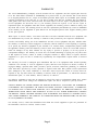
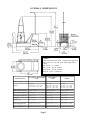
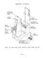
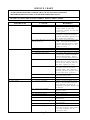
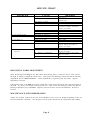
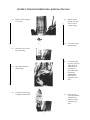
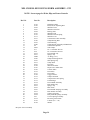
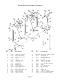
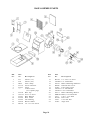
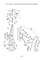
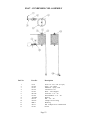
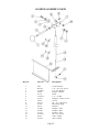
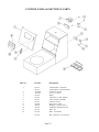
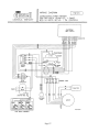
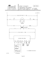
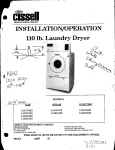
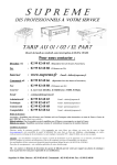
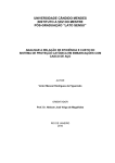
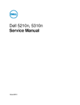
Form Finishers Models: Suzie II Mr. Cissell Ms. Cissell Sensi-Form CISSELL MANUFACTURING COMPANY HEADQUARTERS 831 SOUTH FIRST ST. P.O. BOX 32270 LOUISVILLE, KY 40232-2270 PHONE: (502) 587-1292 SALES FAX: (502) 585-3625 SERVICE/PARTS FAX: (502) 681-1275 THIS MANUAL MUST BE GIVEN TO THE EQUIPMENT OWNER. MANCONS 8/00 IH WARRANTY The Cissell Manufacturing Company (Cissell) warrants all new equipment (and the original parts thereof) to be free from defects in material or workmanship for a period of one (1) year from the date of sale thereof to an original purchaser for use, except as hereinafter provided. With respect to non-durable parts normally requiring replacement in less than one (1) year due to normal wear and tear, including, but not limited to, cloth goods, valve discs, hoses, and iron cords, and with respect to all new repair or replacement parts for Cissell equipment for which the one (1) year warranty period has expired, or for all new repair or replacement parts for equipment other than Cissell equipment, the warranty period is limited to ninety (90) days from date of sale. The warranty period on each new replacement part furnished by Cissell in fulfillment of the warranty on new equipment or parts shall be for the unexpired portion of the original warranty period on the part replaced. With respect to electric motors, coin meters and other accessories furnished with the new equipment, but not manufactured by Cissell, the warranty is limited to that provided by the respective manufacturer. Cissell's total liability arising out of the manufacture and sale of new equipment and parts, whether under the warranty or caused by Cissell's negligence or otherwise, shall be limited to Cissell repairing or replacing, at its option, any defective equipment or part returned f.o.b. Cissell's factory, transportation prepaid, within the applicable warranty period and found by Cissell to have been defective, and in no event shall Cissell be liable for damages of any kind, whether for any injury to persons or property or for any special or consequential damages. The liability of Cissell does not include furnishing (or paying for) any labor such as that required to service, remove or install; to diagnose troubles; to adjust, remove or replace defective equipment or a part; nor does it include any responsibility for transportation expense which is involved therein. The warranty of Cissell is contingent upon installation and use of its equipment under normal operating conditions. The warranty is void on equipment or parts; that have been subjected to misuse, accident, or negligent damage; operated under loads, pressures, speeds, electrical connections, plumbing, or conditions other than those specified by Cissell; operated or repaired with other than genuine Cissell replacement parts; damaged by fire, flood, vandalism, or such other causes beyond the control of Cissell; altered or repaired in any way that effects the reliability or detracts from its performance, or; which have had the identification plate, or serial number, altered, defaced, or removed. No defective equipment or part may be returned to Cissell for repair or replacement without prior written authorization from Cissell. Charges for unauthorized repairs will not be accepted or paid by Cissell. CISSELL MAKES NO OTHER EXPRESS OR IMPLIED WARRANTY, STATUTORY OR OTHERWISE, CONCERNING THE EQUIPMENT OR PARTS INCLUDING, WITHOUT LIMITATION, A WARRANTY OF FITNESS FOR A PARTICULAR PURPOSE, OR A WARRANTY OF MERCHANTABILITY. THE WARRANTIES GIVEN ABOVE ARE EXPRESSLY IN LIEU OF ALL OTHER WARRANTIES, EXPRESS OR IMPLIED. CISSELL NEITHER ASSUMES, NOR AUTHORIZES ANY PERSON TO ASSUME FOR IT, ANY OTHER WARRANTY OR LIABILITY IN CONNECTION WITH THE MANUFACTURE, USE OR SALE OF ITS EQUIPMENT OR PARTS. For warranty service, contact the Distributor from whom the Cissell equipment or part was purchased. If the Distributor cannot be reached, contact Cissell. Page 1 TABLE OF CONTENTS Cissell Equipment Warranty ................................................................................................. 1 Specifications and Dimensions ............................................................................................. 3 Installation Instructions ......................................................................................................... 4 Operation and Safety Precautions ....................................................................................... 5 Operation-Controls........................................................................................................6 Service Chart and Maintenance ......................................................................................... 7-8 Revolving Form Adjustment.........................................................................................8 Instructions for Removing and Replacing Bag............................................................9 Instructions for Tying Lower Tie String ............................................................................ 1 0 Replacement Form Bags ........................................................................................................ 1 1 Instructions for Adjsting Height of Revolving Form...................................................12 Mr. Cissell Form Assembly Parts ...................................................................................... 13-14 Waist, Hip, and Lower Control Parts .................................................................................. 1 5 Base and Blower Parts ........................................................................................................... 1 6 Ms. Cissell and Sensi Form Parts ..................................................................................... 17-18 Suzie II Parts................................................................................................................19 Front and Rear Paddle Assembly.................................................................................20 Steam Column and Piping Parts ......................................................................................... 2 1 Condenser and Spray Gun Parts ...................................................................................... 22-23 Damper Assembly Parts ......................................................................................................... 2 4 Control Panel and Electrical Parts ...................................................................................... 2 5 Wiring Diagrams .................................................................................................................. 26-28 Page 2 OVERALL DIMENSIONS NOTE: Shown with Mr. Cissell Form. To figure the height from floor, add 7-3/4 (19.7cm) to the form heights listed below. Mr. Cissell - 51 (130cm) Ms. Cissell - 58-7/8 (150cm) Sensi-Form - 58-7/8 (150cm) Suzie II - 59-1/4 (150.49 cm) SPECIFICATIONS MS. CISSELL, SENSI-FORM CF600 MR. CISSELL CF100 SUZIE II 1 H.P. Motor 115V, 50/60 Hz., 1 Ph, 12 Amps 230V, 50/60 Hz., 1 Ph, 6 Amps 1 H.P. Motor 115V, 60 Hz., 1 Ph, 6 Amps 230V, 60 Hz., 1 Ph, 3 Amps 230V, 50 Hz., 1 Ph, 3 Amps 1 H.P. Motor 115V, 60 Hz., 1 Ph, 6 Amps 230V, 60 Hz., 1 Ph, 3 Amps 115V, 50 Hz., 1 Ph. 3 Amps Maximum Operating Pressure 100 P.S.I. (6.9 Bars) 100 P.S.I. (6.9 Bars) 100 P.S.I. (6.9 Bars) Boiler Horsepower Required 2.5 H.P. (1.9 kw) 2 H.P. (1.5 kw) 2 H.P. (1.5 kw) Steam Supply & Return Lines 1/2" (1.27 cm) 1/2" (1.27 cm) 1/2" (1.27 cm) Net Weight 220 lbs. (100 kg) 220 lbs. (100 kg) 220 lbs. (100 kg) Shipping Weight 250 lbs. (113 kg) 250 lbs. (113 kg) 250 lbs. (113 kg) Export Shipping Dimensions 61" x 25" x 69" (155 cm x 64 cm x 175 cm) 61" x 25" x 69" (155 cm x 64 cm x 175 cm) 61" x 25" x 69" (155 cm x 64 cm x 175 cm) Export Crate Volume 61 Cubic Feet (1.73 m 3) 61 Cubic Feet (1.73 m 3) 61 Cubic Feet (1.73 m 3) Electrical Page 3 INSTALLATION INSTRUCTIONS NOTE: This machine should be installed by qualified service personnel only. 1. Uncrate the machine. Check the nameplate voltage and current; match it with the power being connected. 2. Set the machine in position and bolt to floor. 3. Connect Water Spray Gun to machine. Remove the Lint Screen to access the connection. Open the valve on the Condenser and replace the Lint Screen. 4. Connect steam supply line as shown in illustration. 5. Connect steam return line as shown. NOTE: Before final return line connection is made, open the steam supply valve and blow all foreign matter out of the steam lines. Failure to do so will cause trap to leak. 6. Make electrical connections in junction box on rear of machine, following applicable electric codes. Include a fused disconnect switch or circuit breaker with slow-blow characteristics and be capable of carrying 15 amps, 115 volts or 8 amps, 230 volts. 7. Install the revolving form on the machine. 8. Turn on the electric power to machine. Remove the plastic cover from the bag. Open the steam lines. 9. Test the machine, following the OPERATING INSTRUCTIONS in this manual. Page 4 SAFETY PRECAUTIONS Please read these warnings before operating or servicing machine. CAUTION: This machine emits hot steam. To prevent burns, avoid contact with hot steam. Before service machine, close steam supply valve and purge lines. CAUTION: Shut off electrical supply before servicing to avoid electrical shock. OPERATING INSTRUCTIONS 1. Machine can be operated from any side. Position foot switches at convenient location. 2. Place garment on form. Adjust shoulder form width by turning knob in either direction. The Mr. Cissell form requires adjustment of the Waist, Hip and Lower control knobs. After adjusting lock the controls by twisting the knobs clockwise. 3. Press the AIR foot switch to operate the blower for sizing the form bag. Size the bag by adjusting the DAMPER CONTROL. Using the Control Panel, press the MODE SELECT until the AIR light glows and press START/CANCEL to operate the blower, then proceed with sizing the bag. 4. Set the three control timers to the recommended settings: Steaming: 6-9 seconds Conditioning: 4-9 seconds Drying: 12-16 seconds These settings should be fine-tuned to the particular garment, steam pressure and ambient conditions. The recommended cycle is the steam/air conditioning and the drying. The control will power up in this cycle. 5. This machine has the ability to pre-steam a garment prior to the automatic finishing cycle. To actuate this cycle, press the MODE SELECT pad until the PRE-STEAM LIGHT glows, then press START. Using the foot switch, press PRE-STEAM. 6. If a cycle is operating, it can be cancelled at any time by pressing any foot switch or control panel pads. Control Panel Page 5 OPERATION - CONTROLS Page 6 SERVICE CHART CAUTION: BEFORE SERVICEING MACHINE, SHUT OFF ELECTRICAL POWER TO AVOID POSSIBLE ELECTRICAL SHOCK. SHUT OFF STEAM SUPPLY AND PURGE PRESSURE FROM STEAM LINES TO AVOID BURNS FROM HOT STEAM. REFER TO PARTS SHEETS FOR CORRECT REPLACEMENT PARTS. PROBLEM (1) No Steam CAUSE A. Steam supply valve closed. B. Electric power off. C. Bad solenoid valve coil. D. Steam timer may slip on shaft and be set on 0. (2) No Air See A. B. C. item 11. Damper closed. Drying timer slipping. Defective motor relay. D. Blower wheel stuck. E . Defective motor. F. (3) Steam Valve Leaks (4) Wet Steam Defective motor capacitor. See items 1B and 11. A. Defective steam valve. A. Trap not operating. B. Check valve problem. C. D. E. F. Strainer clogged. Return line closed. Steam cycle set too long. Steam lines installed wrong. G . Heavy condesate in supply. H . Units not trapped correctly. I . Back pressure in return line. Page 7 REMEDY Open valve in steam supply line. Check for blown fuse, tripped circuit breaker or loose wire connection. Tighten wire nuts and restore power. Disconnect power and measure coil resistance. A good coil should be between 50-125 hms. Replace coil if not within these parameters. Loosen set screw and remove knob shaft. Turn shaft to maximum counter-clockwise position. Attach knob to shaft pointing to 0 and tighten set screw. Open damper. See item 1D. Disconnect and measure resistance of relay coil. A good coil should be between 240-360 ohms. Replace coil if not within these parameters. Check wheel by moving by hand. If wheel rubs or is stuck, loosen the set screws and align the wheel on the shaft. Tighten set screws. Measure the resistance of the black and white wires on the motor terminal board. They should be between 5-20 ohms. Replace motor if not within these parameters. If relay, blower wheel, and motor are good, replace motor. Replace valve. Check size and operation of trap. Refer to the Installation Instructions and make corrections in installation if needed. Replace trap if defective. Check for proper installation. Replace if bad. Clean or replace as needed. Open return line. Reduce steam timer setting. Refer to steam line Installation Instructions. Install by-pass from supply header to return line. Each machine needs separate trap. Check trap installation. Return lines must be gravity fed to condensate tank. Properly vent the condensate tank. SERVICE CHART PROBLEM (5) Water inthe base. (6) Noisy or vibration. (7) Not enough steam. (8) Too much steam. (9) Too much air. (10) Form will not inflate. (11) Timer control does not function. CAUSE A. Wet steam. B. Steam leak in machine. See items 3, 4, and 8. A. Foreign object in blower. B. Wheel out of balance. C. Wheel loose on shaft. D. Motor mount bent. E . Motor bearings bad.. See items 1A, 1D, or 11. Timer set too long. See item 11. Timer set too long. See item 11. A. Damper is closed. See items 2 and 11. A. No power on control. B. Moisture accumulated. C. Timer control bad. REMEDY See item 4. Inspect and repair or replace leaking part. Remove foreign object. Inspect wheel for loose weights, out of round or damage. Repair or replace as needed. Tighten set screws on wheel hub. Repair or replace as needed. Repair or replace as needed. Reset timer. Reset timer. Open damper; check damper control linkage and reapir or replace as needed. Check fuse on back of control, replace if needed. Check for steam or water leaks. Dry out control. Replace timer control. REVOLVING FORM ADJUSTMENT If the Revolving Form drags on the base rather than turning freely, it must be raised. First remove the form by lifting it straight up off the base. Then loosen the Bearing Locknut and turn the Bearing Adjustment Screw counter-clockwise. Check adjustment by replacing form and rotate. Repeat adjustment if needed. If Revolving Form is too high above base, steam will escape from between the base and the bottom of the form. To correct, first remove form from the base. Then loosen the Bearing Locknut and turn the Bearing Adjustment Screw clockwise. Replace form on the base and check adjustment. Repeat if needed. MAINTENANCE RECOMMENDATION Change the air filter located on the rear of the machine at least every six months depending on the use and environmental conditions. See the parts section of this manual for the replacement part number. Page 8 INSTRUCTIONS FOR REMOVING & REPLACING BAG (1) Remove yellow weights, 1 each side. (4) Replace yellow weights, one each side, on end of control strings (3) Lower the control ring inside bag. (2) Tie bottom string in groove and close zipper. Refer to instructions on next page for proper knot when tying string. Straighten bag until control strings are at the sides (1) Place bag over revolving assembly shoulder form, with front of bag toward front of form. t t (2) Raise the lower control ring (inside bag). t (3) Open zipper and untie bottom string (4) Lift bag off of revolving assembly shoulder form. t Page 9 INSTRUCTIONS FOR TYING LOWER TIE STRING Page 10 REPLACEMENT FORM BAGS MS. CISSELL Part No. F1310 MR. CISSELL Part No. FD10 SENSI-FORM Part No. F1311 SUZIE II Part No. F833 Page 11 CISSELL STEAM-AIR FINISHER INSTRUCTIONS FOR ADJUSTING HEIGHT OF REVOLVING FORM Should the revolving form drag on the base rather than turn freely, the form must be raised. Conversely, if the revolving form hides too high above the base, permitting steam to escape from the space between the form and base, the form must be lowered. WHEN ADJUSTMENT MUST BE MADE, REMOVE REVOLVING FORM BY SIMPLY LIFTING IT STRAIGHT UP OFF THE BASE. PROBLEM: Revolving form drags on base. TO CORRECT: Loosen F286 Bearing Lock Nut. Turn F287 Bearing Adjustment Screw COUNTERCLOCKWISE CHECK ADJUSTMENT: PROBLEM: Replace revolving form on base. Rotate form. If perfectly adjusted, form will rotate freely and snugly on felt seal around top of base. If form is still too low... or too high...repeat adjustment until it is correct. Revolving Form rides too high above base. TO CORRECT: Loosen F286 Bearing Lock Nut. Turn F287 Bearing Adjustment Screw CLOCKWISE. CHECK ADJUSTMENT: Replace revolving form on base. Rotate form. If perfectly adjusted, form will rotate freely and snugly on felt seal around top of base. If form is still too high... or too low... repeat adjustment until it is correct. Page 12 MR. CISSELL REVOLVING FORM ASSEMBLY Page 13 MR. CISSELL REVOLVING FORM ASSEMBLY - F22 NOTE: See next page for Waist, Hip, and Lower Controls. Ref. No. 1 2 3 4 5 6 7 8 9 10 11 12 13 14 15 16 17 18 19 20 21 22 23 24 25 26 27 28 29 30 31 32 33 34 35 36 37 38 39 40 41 42 43 44 Part No. Description F192 F381 F492 F493 F494 F336 F197 F317 F533 F140 F279 F289 F9 F842 F11 F24 F432 F433 F888 F240 F243 F237 F267 F304 F303 F302 F332 F333 F104 F335 F151 F137 F334 F434 F435 F427 F436 F437 F218 F438 F63 F534 F122 P104 Insulating Gasket Knob, Pin, & Adjusting Rod Shoulder Form Shoulder Extension Bearing Plate Shoulder Link Shoulder Tension Spring Shoulder Lever Control Box & Pan Assembly Clamp Bearing Bolt Thrust Bearing Cup & Bearing Assembly with Hardware Cloth Steam Spreader Vent Clamp* No. 11 Wooden Sleever* No. 24 Wooden Sleever* Front Paddle only Sponge only E Ring (3/16) Clamp Slide Support Pin Slide Spring Clip Clamp Slide Pivot Pin Waist Index Plate Hip & Lower Index Plate Control Slides Front Plate Front Latch Trigger Release Clamp Latch Rod Compression Latch Spring Latch Plunger Front Handle Assembly Rear Paddle only Sponge only Back Latch Front Paddle & Sponge Assembly Rear Handle Assembly Clamp Leaf Spring Rear paddle & Sponge Assembly Covered Spring Assembly Revolving Form Frame Locknut (1/4 - 28) Washer *Not part of F22 Assembly Page 14 WAIST, HIP, AND LOWER CONTROLS Ref. No. Part No. Description 1 2 3 4 5 6 7 8 9 10 11 12 13 14 15 16 F322 F323 F321 F301 F300 F319 F318 F377 F324 F325 F490 V2 P39 F429 F439 F440 Waist Control Knob Hip Control Knob Lower Control Knob Spacer Spacer Actuating Lever Actuating Lever Bearing Pin Bearing Pin Connecting Link Draw String Lever Cotter Pin Yoke, Pin & Cotter Pin Tension Spring Hip Lever Rod Waist Lever Rod Ref. No. 17 18 19 20 21 22 23 24 25 26 27 28 29 30 31 Page 15 Part No. Description 040113282 Bead Chain (order by length) F442 Cord, Beads, & Couplings Set F443 2 Pins & 4 E Rings F888 E Ring F444 2 Pins & 4 E Rings F445 2 Pins & 4 E Rings F446 Swivel & Chain Coupling F447 Spacer F448 Lower Swivel Arm F449 Hip Swivel Arm F450 Lever F331 Bearing Pin F451 Lower Lever Rod F1003 Lower Lever Rod Assembly F1004 Hip Lever Rod Assembly BASE ASSEMBLY PARTS Ref. No. 1 2 3 4 5 6 7 8 9 10 11 12 13 Part No. F11 F24 F842 F1319 F1427 ---- Description Sleever (11) Sleever (24) Vent Clamp Screen Retainer Filter Control Panel (see separate page) F1238 Base Top TU7733 #8 x 1/2 Screw F1203 Base Bottom F1290 Rear Jacket F1264 Fan Housing FG292 Blower Wheel RC344 1/4 - 20 x 3/4 Screw Ref. No. 13 14 15 16 17 18 19 20 21 22 23 24 25 Page 16 Part No. Description RC344 TU2846 AF130 SB180 F1265 TU2947 TU2814 AF131 MTR297 C363 FG226 C249 F1463 1/4 - 20 x 3/4 Screw 1/4 Lockwasher Motor Mounting Hardware Junction Box Cover Lower Rear Cover 1/4 Flat Washer 5/16 Lockwasher Motor Mounting Bracket Motor, 115-230/50-60/1 5/16 x 1-1/4 Bolt Inlet Cone 5/16 Hex Nut Angle Seal MS. CISSELL, SENSI-FORM REVOLVING FORM ASSEMBLY Page 17 MS. CISSELL, SENSI-FORM REVOLVING FORM ASSEMBLY Ref. No. Part No. Description 1 F517 2 3 4 5 6 7 8 9 10 11 12 13 14 15 16 17 18 19 20 21 22 23 24 25 26 27 28 29 30 31 32 33 34 35 36 37 38 39 40 41 42 43 44 45 F381 F192 F493 F492 F494 F197 F336 F317 TU3477 FB187 FB185 F1242 TU3480 F431 PT355 F860 F859 F279 F1309 FG277 TU4787 AF207 AF176 F433 F432 F237 F243 F888 F240 F267 AF157 F122 FG135 F359 FG288 F489 FG450 F197 F950 FG443 FB187 F901 F1188 F949 Adjustable Shoulder Form consists of Parts 2-9. Knob & Rod Assembly Insulating Gasket Shoulder Extension Shoulder Bearing Plate Tension Spring Shoulder Link Shoulder Lever #10 - 24 x 1/2 Screw #10 Lockwasher #10 - 24 Hex Nut Revolving Form #10 - 24 x 5/8 Screw Bearing Cup 1/4 Hex Nut Wa s h e r 1/4 - 20 x 1/2 Screw Thrust Bearing Shell Assembly Stud 3/8 - 16 x 9/16 Jam Nut Cloth Cover Front Paddle Clamp Assembly Sponge Front Paddle Channel Clamp Slide Slide Spring Clip Retaining Ring Pin Pivot Pin Trigger Release Assembly 1/4 - 28 Hex Nut Handle Retaining Ring Pin Retaining Ring Latch Pin Spring Wa s h e r Latch Rod Lockwasher #10 - 24 x 3/8 Screw Leaf Clamp Spring & Pivot Pivot Pin Page 18 SUZIE II REVOLVING FORM FG236 ITEM# PART# DESCRIPTION 1-2 F381 3 4 5 6 7 8 9 10 F49 F192 F492H F493 F336 F494H F197 F317 Knob, Shoulder Adjustable Rod & Pin Rod & Pin Shoulder Lever Pin* Pyroid Gasket Shoulder Sliding Shoulder Shoulder Connecting Link Bearing Plate Shoulder Tension Spring Shoulder Lever 11 12 13 14 15 16 17 18 19 FG219 FG220 FG222 FG223 TU2089 FG201 FG444 FG202 F289 Frame Assembly Pivot Plate Assembly 3-5/8" x 1/4" Pin 4-1/2" x 1/4" Pin Spring Support Rod Yoke Weight Ring Bearing Assembly 21 22 23 24 25 26 27 28 29 30 31 32 33 34 35 36 FG156 AF207 FG264 TU3478 P104 FB185 TU3477 M271 PT355 F860 F859 F359 TU3480 F122 FB201 FG284 Turning Arm Knob Cloth Steam Spreader Shell Assembly #8-32 x 1/2" Pan Head Screw* 1/4" Brass Cut Washer* #10-24Hex Nut* #10-24 x 1/2" Flat Head Screw* 3/16" Split Lockwasher* 1/4"-20 S.S. Hex Head Nut 1/4" S.S. Split Lockwasher 1/4"-20 x 1/2" S.S. Screw* Retaining Rings* #10-24 Round Head Screw* 1/4"-28 Brass Nut* Cotter Pin* 1/4" x 5/8" Roll Pin* F833 F816 FG310 FG311 Nylon Bag Net Overbag Bag Weights 50 CY. 2" x 1-1/8" Bag weights 60 CY. 2" x 1-1/2" F517 Adjustable Shoulder Assembly FG290 Revolving Form Frame Assembly FG291 Revolving Form Shell Assembly Not Illustrated (*Shipped as a package of 6) Page 19 FG137 Front Paddle Assy 36 Ref. No. 1 2 3 4 5 6 7 8 9 10 11 12 13 14 15 16 Part No. Description FG137WH FG164WH F433 F432 F237 F243 F240 F267 F218 F104 F949 F1121 F136 FG443 FG135 F197 FG450 FG287 Front Paddle Assy 36 Rear Paddle assy 24 Sponge (36) Paddle Channel (36) Clamp Slide Slide, Spring (2 Reqd) Slide Pin, (2 Reqd.) (1/8) Pivot Pin (1/8) Clamp Leaf Spring Handle Trigger Handle Pin (3/16) Rod Hinge Pin (3/16) Rod Hinge Latch Rod Handle Welded Assy Spring Latch Pin Clamp Base FG164 Rear Paddle Assy 24 Ref. No. Page 20 Part No. 17 18 19 20 21 22 23 FG277 FG288 F435 F434 F901 F842 F904 24 25 26 27 28 29 30 31 32 F24 F11 ET183 F888 F122 F950 F489 TU4787 FB187 Description Stud Pin (3/8) Sponge (24) Paddle Channel (24) #10 - 24 x 3/8 Hex. Hd. Screw* Vent Clamp Sandpaper & Sponge Set for F842 #24 Sleever #11 Sleever E Ring for 1/8 Pin* E Ring for 3/16 Pin* 1/4 - 28 Brass Nut 3/8 Cut Washer* E Ring for 3/8 Rod* 3/8 - 16 Hex Nut* #10 Split Lockwasher* STEAM COLUMN & PIPING PARTS Ref. No. 1 2 3 4 5 6 7 8 9 10 11 12 13 14 15 16 Part No. F1227 F1269 F286 F287 F542 F1292 390401016 F1289 F1296 F1394 F1397 F894 IB139 VSB134 IB140 F1449 Ref. No. Description Steam Chamber Column Bearing Support Frame Bearing Locknut Bearing Adjustment Screw Pipe Plug Union 3/8 x 2 Pipe Nipple Solenoid Valve Steam Nozzle Steam Spreader Pipe Nipple (3/8 x close) Drawband 3/8 - 16 x 1-1/4 Bolt 3/8 Lockwasher 3/8 Flat Washer Connector Flare 17 18 19 20 22 23 24 25 26 27 29 30 31 Page 21 Part No. Description F1456 Coil Supply Tube Assy (CF100) F1458 Coil Supply Tube Assy (CF600) F1324 Steam Coil (CF100) F1288 Steam Coil (CF600) F1399 1/4 - 20 x 1 Screw (see page 19) 400518040 Insulation (order by length) FG143 Pipe Tee SC196 Pipe Weldment SC505 Coupling F1461 Elbow w/Fitting F1439 Condenser F896 Drawband Eye F1457 Coil Return Tube Assy (CF100) F1459 Coil Return Tube Assy (CF600) F1448 Column Supply Tube Assy Ref. No. 1 2 3 4 5 6 7 8 9 10 11 Part No. Description J42 P530 SGV35 SF274 SG38 J3 136067752 F1273 OP225 F1441 SG043 SK043 Hose Clamp Elbow - 1/4 x 1/8 Adapter Spray Gun Hose Spring Small Hose Clamp Insulation (order by length) Spray Gun Pipe Straight Connector - 1/8 NPT x 1/4 Tube (see page 19) Spray Gun Repair Kit for Spray Gun consists of a plunger tube, strainer, nozzle, and 2 gaskets Page 22 F1447 - CONDENSER COIL ASSEMBLY Ref. No. Part No. Description 1 2 3 4 5 6 7 8 9 10 11 12 13 F725 F1440 F1441 F1439 F1445 RC382 F1446 TU2847 PT355 OP297 BR61 SU65 F1461 Screw 10 - 24 x 5/8 (2 reqd) Valve - 1/4 Globe Manifold - Spray Gun Condenser Coil Plate - Coil Support Lock Nut - 1/4 - 20 Threaded Rod - 1/4 - 20 Wa s h e r Nut - 1/4 - 20 Compression Fitting Bushing Nut Compression w/PU8 Bead Elbow Page 23 DAMPER ASSEMBLY PARTS Ref. No. Part No. Description 1 2 3 4 5 6 7 8 9 10 11 12 13 14 15 16 17 D16 RC344 TU2847 F660 F750 TU4934 F1216 F664 SV332 F358 F639 F1280 F1283 F1222 TU7733 F645 F1438 Control Knob 1/4 - 20 x 3/4 Screw 1/4 Cut Washer Rubber Washer Shaft 1/4 - 20 Nut Damper Control Lever Swivel #8 - 32 x 3/8 Screw Retaining Ring Wa s h e r Damper Tube Damper Wire Damper Plate #8 x 1/2 Screw Tube Clamp Wire Clamp Page 24 CONTROL PANEL & ELECTRICAL PARTS Ref. No. Part No. Description 1 F1301 F1305 TU8629 TU7733 F1300 F1302 F1243 F1259 ET250 SF259 F1406 F1325 F1396 Transformer (120/24V) Transformer (200-240/24V) Terminal Board #8 x 1/2 Screw Relay Capacitor (1 H.P. Motor) Foot Switch Assembly Control Panel Electronic Timer Damper Control Label #8 Black Anodized Screw Wire Tie Wire Tie Mount F1304 Wire Harness (not shown) 2 3 4 5 6 7 8 9 10 11 12 Page 25 Page 26 Page 27 Page 28