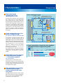
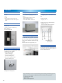
1
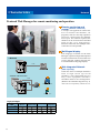
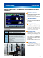
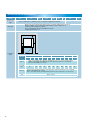
Platinous J Series
Temperature & Humidity Chamber · Low Temperature (& Humidity) Chamber
Ultra Low Temperature (& Humidity) Chamber · High Temperature & Humidity Chamber
Low Humidity Type (Low) Temperature & Humidity Chamber · Clean Temperature & Humidity Chamber
CAT.NO.E11110-V1305
The Platinous J Series – The next generation
of environmental test chambers
Its rich collection of advanced features has quickly made the Platinous J Series the environmental
test chamber of choice over the world.
At the very top of the list of impressive Platinous J Series features is a dramatic reduction in
power consumption, thanks to a new energy saving, highly reliable cooling system.
The new N-instrumentation allows J Series chambers to support easy-to-use networking system.
A comprehensive selection of options along with improved installation procedures creates a new
structure customizable to meet individual needs.
Backed-up with more than 50 years of brand history, and a foundation based on solid experience,
our technology is constantly being improved and polished in order to ensure our customers
unmatched reliability, performance, and safety.
Type 1
1
Type 2
Contents
● Communication Network
p.3 to 5
● The N Controller
p.6 to 7
● Energy Saving Features
p.8 to 9
● Common Features
p.10 to 13
● High Temperature & Humidity Chamber PHP
p.14
● Clean Temperature & Humidity Chamber PCR
p.15
● Low Humidity Type (Low) Temperature &
Humidity Chamber PDR/PDL
p.15
● Series Configuration
p.16
● Installation Requirements
p.17
● Specifications
p.18 to 25
● Temperature & Humidity Control Range Chart
Type 3
p.26
● Option list by model
p.28 to 29
● Options
p.30 to 38
Type 4
* Equipped with options.
2
Characteristics
Network
Featured Web Manager for remote monitoring and operation
Remote monitoring and
control (Ethernet connection)
● Email alert
LAN
PC
Intranet
(company LAN)
Mail server
Platinous J
Mobile phone
Smartphone
A unique web application allows the
u s e r t o mo n it o r t he ch a mb e r, s e t
programs, and start and stop operation
from a PC connected
to the chamber
PC
LAN’s port. No software required, the
chamber can be accessed
and controlled
携帯電話
f r o m a ny P C v スマートフォン
i a a we b b r ow s e r.
Wireless connection and multiple units’
connection are also possible.
タブレットコントローラー
(オプション)
Multilingual
display
The language available for the Web
Manager (Japanese/English/Simplified
Chinese/Traditional Chinese/Korean)
can be changed without affecting the
N-instrumentation language display.
● Network
LAN
Web Integrated Network
(Sold separately)
PC
Check the status of multiple chambers
f r o m a s i n g l e s c r e e n (u p t o 10 0
chambers, web-compatible devices
on ly). T h is e q u ipme nt i nclude s a
scheduler ideal for test management.
(Refer to the schematic diagram on p. 4)
Platinous J
• Wireless LAN connection
LAN
Tablet controller
Wi-Fi router
Platinous J
Smartphone
Login privileges
Screen
Privileges
Chamber
Monitor
Constant Mode/
Program Setup
Run/Stop
Administrator
Operator
User
3 ● Program copy and computer editing
Device
Configuration
*Please ask us for compatibility with other devices.
Characteristics
Network
Programming (test profile)
● Programming
● Run/Stop
● Chamber monitor
● E-mail alert
Program patterns stored on the chamber
can be modified from the web browser.
Run/Stop
Even when the chamber is OFF (but the
breaker is ON), it is possible to select
the desired program pattern and start
chamber operation. It is also possible to
turn the chamber power OFF from the
PC.
Recording and management
of data
The Web Manager saves data (approx.
30 - se c ond i nt e r va l s), t h at ca n b e
accessed from a PC, and displayed as a
graph on the browser (up(別売)
to 100 days of
Web統合管理システム
data). It is also possible to save the data クライアントPC
on the PC in CSV for mat (commaWeb統合管理システム
separated values).
● Email alert
LAN
E-mail alert
When an alarm is triggered, an e-mail is
sent to the registered PC or mobile
address. Multiple addresses
can be set
LAN
form the Device Configuration screen.
イントラネット
LAN
LAN
*Requires an intranet environment capable of
sending e-mail.
Platinous J
PC
Intranet
LAN LAN)
LAN
(company
WEB
マネージャー
Mail server
RS-485
RS-485
Mobile phone
Smartphone
Web camera (option)
Install a web camera in front of the
chamber window to monitor your test
プラチナス Jシリーズ
area from the browser.
ビルドインチャンバー
Eシリーズ
冷熱衝撃装置 TSA
小型環境試験器
● Network
Web Integrated Network (Sold separately)
LAN
LAN
PC
Platinous J
LAN
Intranet
Client PC
Platinous J
• Wireless LAN connection
LAN
LAN
WEB MANAGER
RS-485
Walk-in Type Chamber
E Series
Tablet controller
Web Integrated Network
Thermal Shock Chamber
Wi-Fi TSA
router
LAN
WEB MANAGER
Platinous J
RS-485
Bench-Top Type Chamber
Smartphone
4
Characteristics
USB
Pattern Manager Lite software: Get the most out of USB memory
Replicate program patterns
● Program copy and computer editing
C opy p r og r a m p at t e r n s f r om one
chamber to transfer to another without
using a PC.
* USB memory is not included.
Copy
Pattern Manager Lite software
All chambers are delivered with the
Pat ter n Manager Lite, computer
application software used to edit program
patterns, display graphs of temperature
and humidity and log data.
Edit
● Program editing
● Log data display
* Refer to the instruction manual DVD for software
installation
Supported languages
Japanese or English lang uages are
available.
Continuous logging via
external memory
Temperature and humidity data can be
logged directly on the USB memory.
Reference: A 4GB USB memory device could
contain 10 years’ worth of temperature and humidity
log data recorded at 1-second interval.
Backtrace function
USB memory port
● Test Navi (http://www.test-navi.com/eng/index.html)
This website provides practical knowledge on environmental testing
that ESPEC has acquired through years of experience, as well as
covering everything from the fundamentals to the latest information on
environmental and reliability testing.
Product registration
membership Website
Download Pattern Manager and
WEB manager information.
Environmental Test
Standards
For Pattern Manager Lite
Test methods download
5
· Updates for product
software
Download
· Search for environmental
test standards
· Download test profiles
from a list of environmental
test standards
Backtrace data are created when the
chamber triggers an alarm. All items
required for chamber control including
set temperature and humidity, measured
temperat ure and humidity, etc. are
recorded for the period before and after
the alarm was triggered.
(For details on how to use the backtrace
function, refer to p. 13)
Download test profiles from
international standards
ESPEC’s reliability test information
website, “Test Navi” compiles various
test standards used for environmental
testing.
Download the program patter ns of
various test standards and copy them to
your chamber, or edit them using the
Pattern Manager Lite.
Characteristics
N-Instrumentation
High-speed processing N-Instrumentation features improved operability
and legibility
Tabbed user interface
Provides high resolution and fast display.
Tabs at the bottom of the screen make it
easy to activate any section.
Eco operation settings are easier than ever.
Register test patterns
Up to 40 patterns for program operation
and 3 patterns for constant operation can
be registered.
Trend graph output
Trend graphs can be displayed according
to set conditions and data can be recorded
in internal memory. Data can also be
recorded directly onto USB memory for
backup purposes. Measurement intervals
and other settings can be changed.
N-Instrumentation
Operating mode Constant operation, program operation, remote operation, stop
3 patterns
40 patterns (99 steps per program)
Setting range
Constant setup
Program setup
Language
English, Japanese, Chinese, Korean (switch without restarting)
External
memory
function
• Interface
USB 2.0 standard compliant (A-type connector)
• Supported functions
Write log, Read/Write program (application software: Pattern
Manager Lite), write backtrace
Web function
• Interface
Ethernet port (100base-TX)
• Server functions
Remote monitor/setup (constant, program)/operation, email alert,
Web Manager functions
• Browser
Windows internet Explorer 7 or 8
Information screen
T he infor mation section displays
information on the chamber status, such
as defrosting, or humidifying tray water
auto refill.
Messages displayed according to operating
timer inform you of the humidifier
maintenance checks, condenser filter or
strainer checks.
It is also possible to register and use
additional notification items.
Multilingual display
A simple operation changes display text
to Japanese, Chinese (simplif ied,
traditional), or Korean. Select the language
that suits your needs.
6
Characteristics
N-Instrumentation
● Detailed settings for each step
● Constant setup
Up to 40 patterns for program operation
can be registered.
Configure settings such as refrigerator
and time signal settings.
Up to 3 patterns for constant operation
can be registered.
● Sampling settings
● Trend graph display
● Graph data writing settings
Select the recording cycle.
1-second interval:18 hours
5-minute interval: 227 days
The actual measured values and the set
values are displayed on a graph.
The data that has been recorded can be copied
to a USB memory device. The data can also be
recorded directly to a USB memory device.
● Timer settings
● Hour meter with reset
● Screen settings
For each timer, configure the start and
stop times or the time setting.
Start, pause and reset the timers, or set
them to automatic.
To set humidity display, language display
etc.
● Notification function
● Information
● Alarm notification
Set the cleaning period of the condenser
filter and humidifier pan. An arbitrary
notification can be assigned to No. 3.
The details of the blinking INFO icon are
displayed.
When an alarm occurs, the alarm or
warning items are displayed.
7
● List of programs
Characteristics
Energy savings
Energy savings and high performance achieved thanks to
the refrigeration system
• Temperature control
Operating conditions
0.50
1.00
1.50
2.00
2.50
PL-3
+60°C
PR-3
Energy
savings rate
PU-3
66% max.
PL-3
+20°C
PR-3
PU-3
• Temperature & humidity control
Operating conditions
+85°C/
85%rh
+20°C/
40%rh
0.50
1.00
Power consumption (kWh)
2.00
2.50
1.50
Energy
savings rate
PL-3
70% max.
PR-3
PL-3
PR-3
Power consumption comparison when equipped
with the DC inverter energy saving system
J Series
K Series
Operating conditions
0°C
PL-3
–10°C
PU-3
–20°C
Power consumption (kWh)
0.50
1.00
1.50
2.00
2.50
Energy
savings rate
48% max
The J Series switches between large and
small refrigerators, depending on the
chamber capacity and the temperature and
humidity range; it also handles precisely
various heat loads by using a multicompressor system that manage a main
and a sub-circuit.
From the first Platinous Series sold in 1961,
we have been strongly committed to response
and accuracy in the control of temperature
and humidity (air-conditioning system), by
adopting our own unique systems.
In this series, we made further improvements
of our control system by focusing on energy
savings more than ever.
One of these enhanced features is the PID
control of refrigeration capacity. The Smart
Refrigerator & Dehumidifier System can
control minutely both heating and cooling
at minimal levels, thanks to the new
N-instrumentation embedded in the
chamber. PID control applies to both main
and sub refrigeration circuits.
Energy savings principle diagram
Heater output
J Series
K Series
Power consumption (kWh)
Smart Refrigerator and
Dehumidifier System with PID
control (Patent pending)
Test area
stabilization
point
Refrigeration
output
Power consumption comparison (example)
K Series
Heating/
humidifying
Cooling/
dehumidifying
J Series
Heating PID control
N-Instrumentation
Refrigeration
PID control
N-Instrumentation
Increased reliability of the
refrigeration circuit
K Series (PL - AC inverter spec.)
Chamber equipped with shelves (option)
We have installed an injection circuit for
compressor cooling. A heater exchanger
is also installed in the refrigeration system
and the compressor is protected from
refrigerant accidentally flooding back.
8
Characteristics
On chambers equipped with the 400 W
refrigerator, the Smart Refrigerator &
Dehumidifier System controls the operation
when stable at constant ranges above 50°C
/40%rh, after the chamber activated the
sub refrigerator to run at minimum
capacity. Chambers using this double
energy saving control can run with the
best energy-saving rates.
For example, the PL−3J power consumption
can be cut by 70% max. under 85°C /85%rh
conditions. (Compared to previous
model)
PR-3
PL-3
PR-3
+85°C/
85%rh
+20°C/
40%rh
PL-3
If the chamber is often used in low
temperature ranges, you can select the DC
inverter control refrigeration system with
excellent energy saving characteristics in
low temperature ranges.
High temperature & humidity
chamber PHP provides
energy savings under high
heat loads
The PHP chamber features a built-in heat
pipe. This ensures low energy consumption
even in tests involving high heat loads.
(For details, refer to page 14.)
9
0.50
Solenoid
valve
1.00
Power consumption (kWh)
2.00
2.50
1.50
Sub refrigeration circuit Energy
savings rate
PL-3
PR-3
70% max.
Compressor
400W
Expansion
mechanism
Heat
exchanger
Power consumption comparison when equipped
with the DC inverter energy saving system
J Series
K Series
Operating conditions
0°C
PL-3
PL-2/3/4, PU-2/3/4
Heat
exchanger
PR-3
–10°C
Optimized for energy savings
in low temperature ranges
–––DC inverter (option)
66%
• Temperature & humidity control
Operating conditions
2.50
Compressor
Energy
1.5 kW
(Type 4: savings rate
3 kW)
max.
Accumulator
Expansion
mechanism
PU-3
2.00
1.50
Condenser
PL-3
PU-3
+20°C
1.00
Bypass
circuit
Test
area
+60°C
0.50
Condenser
PL−2/3/4, PU−2/3/4, PSL, PG, PDL, PCR
Operating conditions
Solenoid
valve
Bypass
circuit
A sub refrigeration circuit for
further energy savings
Electronic
• Temperature control
expansion valve
Intermediate
injection circuit
The electronic expansion valve located on
the cooling side, has an extended water
flow control rate (0 to 100%), while the
Smart Refrigerator & Dehumidifier System
controls the refrigeration capacity to its
minimum. Consequently, while creating
a highly accurate temperature and humidity
environment, the refrigeration circuit
suppresses heater output and reduces
power consumption of both refrigerator
and heater.
J Series
K Series
Power circuit
consumption (kWh)
Main refrigeration
● New refrigeration circuit
Cooler
(Main refrigeration circuit)
Power consumption comparison (example)
Cooler
Newly developed
refrigeration circuit
Energy savings
PU-3
–20°C
Power consumption (kWh)
0.50
1.00
1.50
2.00
2.50
Energy
savings rate
48% max
Characteristics
PR · PL· PSL
100
98
90
90
TheRelative
refrigeration
system features an electronic
80
humidity
Standard control
temperature
70
auto-expansion
valve
with non-step
% rh
and humidity
60
control
range
which realizes
high-precision temperature
55
50
and humidity control within a wide low
40
temperature
32 area of +10ºC and low humidity
30
Low humidity
area of 20%rh
20 (at +70 to +85ºC).
control range
80
70
Relative 60
humidity 50
% rh 40
30
20
15
10
0
5
10
20
30
40
15
50
60
Temperature °C
70
80
90
100
85
* With no specimen and under ambient temperature at +23°C.
* Continuous humidity operation at +40°C or lower because of frost on the cooler.
PHP
100
95
90
85
80
75
70
98
10
0
10
20with
30 a
40 50 60 70 80 90
Standard equipped
18
85
Temperature
°C
humidifier delay15function
to prevent
* With
no specimen and under
temperature at +23°C.
dew
condensation
onambient
specimens
* Restrictions on continuous humidity operation at +40°C or lower be
on the cooler.operation starts after the
Humidifier
temperature is attained in order to reduce
dew condensation
and its associated
PCR
drawbacks.
100
85
90
80
Quick lead-time
for extended
70
range of60options
55
60
Relative
humidity 50
% rh 40
30
55
45
20
10
0
Achieve high-precision
PDR · PDL
temperature
and humidity
control100
in a wide testing range
10
20
50 60 70 80 90 100
45 55
75 85
95
Wide-view
door
Temperature °C
At ambient temperature at +23°C.
At ambient temperature at +30°C.
At ambient temperature at +40°C.
Door with viewing window
30
35
40
* With no specimen.
Door without viewing window
More
than50100 options are available for
Relative
40
selection,
humidity and we arranged process so that
30
%
rh
compatibility
to any model of the Series can
20
be done smoothly
according to your needs.
10
Even when selecting
a number of options,
0
10 20 30 40 50 60 70 80 90
we can deliver a customized
product in
Temperature °C
15
85
short time. Retrofit options are also available
* With no specimen and under ambient temperature at +23°C.
as option
package (easy installation).
* Restrictions on continuous humidity operation at +40°C or lower be
frost on the cooler.
A variety of doors are
available for selection (Option)
Several types of chamber doors are
available for selection: a standard type
with viewing window, a door without a
viewing window, and an all-glass door
that allows you to check the inside of the
whole test area.
Furthermore, you can customize the door
according to your application by, for
example, adding hand-in ports to the door
or installing an inner glass door to the
chamber door.
10
Characteristics
All-glass wide-view door
(Option) PR-2·3·4 PL-2·3·4 PU-2·3·4
An all-glass wide-view door provides an
unrestricted view of every bit of space
inside the chamber. This option is the
optimum choice when observation of or
operations on a specimen are required
during testing.
The entire surface of the door is made of
multi-layer EC (metal film deposition)
glass that withstands temperatures from
-40 to +120ºC (+100ºC when hand-in ports
are equipped). Temperature differential
with the outside of the chamber can be
controlled to suppress the formation of
condensation on the glass surface.
The glass can be equipped with hand-in
ports for models type 3 and 4. Areas around
the hand-in ports are designed to suppress
condensation, which tends to form there.
(Japanese patent number 4137894)
Wide-view door (with hand-in ports)
Right-side cable port
(Patent pending)
Until now, Platinous chamber were
equipped with a control panel and
machinery compartment, preventing
access of the test area on the right side.
In the J Series, it is now possible to add a
cable port on the right side of the chamber
(option).
Right side now includes a customer space,
where we can add several options, such
as the right side cable port, but also
decrease protrusions, according to the
customer requests.
Right-side cable port
Combination with ESPEC
evaluation systems
Even more accurate ion migration
evaluations can be performed by connecting
a Platinous J Series to our AMI System
(sold separately).
When the right side cable port is equipped,
free access on both sides of the chamber
is available, and it is easier to install
multiple units.
11
Ion Migration Evaluation System connection (example)
Characteristics
※当社器比
Automatic humidifier water
replacement
Humidifier stagnant water contains
impurities and is a cause of trouble, so the
chamber now features a function that
automatically replaces the water at the
period set from the controller screen.
Chamber detailed settings
Water supply setting
Water supply system
Several options to supply water to the
chamber are offered, including direct tap
water connection, pure water, additional
tanks, etc.
Wick replacement (Patent pending)
The difficulty in replacing the wet-bulb
wick has been improved by changing the
shape of the wick's plug part to allow
smooth replacement work.
Water tank
Additional water supply tank (option)
Easy filter cleaning
The condenser filter can be easily attached
and removed from the left side of the
chamber to make cleaning even easier.
Chamber restricted use with
the power key switch
Wick inside chamber
Condenser filter
It is now possible to lock the chamber door
to prevent accidental operation of the
chamber during testing.
The handle part design has also been
improved so the door closing is easier and
safer.
As an option, a power key switch can also
be equipped to control the start and stop
of the chamber.
Reuse, resource savings
The test area size is the same as the
previous Platinous Series so shelves and
shelf brackets can be reused.
Door handle lock
Power key switch (option)
12
Characteristics
Backtrace function
When the chamber stops because of
trouble, the operation state just before the
chamber stops is automatically recorded
and saved. Saved data can be transferred
by USB memory.
Attach this data file to an email to ESPEC,
and we will perform troubleshooting.
Online diagnostics services
Diagnostics service is available using the
backtrace data from the time of trouble.
Send the backtrace data to ESPEC via
email; we will analyze the cause of the
trouble and report the diagnosis back to
you.
This service ensures accurately-performed
diagnosis so that, in the case that
repair work is required, appropriate
troubleshooting will be prescribed
ensuring reduced testing downtime.
Backtrace setting
●O
nline diagnostics services (http://www.espec.co.jp/english/support/onlinediagnosticsservice.html)
International safety standard
compliance
Complies with Safety of Machinery
(ISO 12100), Low Voltage (IEC 60204),
EMC (IEC 61000-6-2, IEC 61000-6-4).
● International safety standard compliance
220, 380 and 400V AC spec. are in compliance with the
requirements of the European Community Directives (hereinafter
referred to as CE spec.)
· Machinery Directive 2006/42/EC
· Low Voltage Directive 2006/95/EC
· Electromagnetic Compatibility Directive 2004/108/EC
· Pressure Equipment Directive 1997/23/EC
13
Characteristics
PHP
High temperature & humidity
chamber featuring a heat
pipe for cooling
消費電力量比較(例)
Jシリーズ
Kシリーズ
・ 温度制御
消費電力量
(kWh)
運転条件
0.50
1.00
1.50
2.00
2.50
PL-3
+60℃
PR-3
66%ダウン
省エネ率
最大
%
66
PU-3
56%ダウン
Test
55%ダウ
ン
can be conducted at
95°C/95%rh
59%ダウン
PL-3
+20℃
PR-3 High Temperature & High Humidity Chamber (Type 2, Type 3, Type 4)
PU-3
Structure diagram of heat pipe
Low-temperature area
・ 温湿度制御
0.50
運転条件
1.00
1.50
PL-3
+85℃/
85%rh
(vapor becomes condensed)
消費電力量(kWh)
2.00
2.50
省エネ率
Heat release
最大
%
70
Vapor flow
PR-3
PL-3
+20℃/
40%rh Heating
PR-3
Sealed vessel
Condensate liquid
Heated area
(operating fluid evaporates)
DCインバーター搭載時消費電力量比較
Inside of the chamber
Outside of the chamber
Jシリーズ
Kシリーズ
運転条件
Allowable heat
0℃
消費電力量
(kWh)
0.50
1.00
2.00
2.50
load (Chamber temperature and humidity: +85°C/85% rh)
Model
PL-3PHP
PL
2J
PU-3
300 W
100 W
3J −20℃
300 W
100 W
4J
600 W
100 W
−10℃
1.50
ESPEC has developed a high temperature
and humidity chamber with superior
energy-saving efficiency.
Heat pipes are used for the cooling system,
which
means that the refrigeration system
65%ダウ
ン
省エネ率
does
26%ダウ
ン not use electrical power to reduce
最大
66%
power consumption.
省エネ率
最大
%
48
Control via the heat pipe is not affected
by dehu m id if icat ion t h roug h t he
refrigerator, achieving wider control range
70%ダウ
forンhigh temperature and high humidity.
23%ダウン
65%ダウン
省エネ率 the heat load
Accommodates
最大from
70% specimen
generated
25%ダウン
28%ダウン
As the refrigerator operates even under
high temperature and high humidity,
excess capacity is not available to treat
the heat generated from specimen. As a
result, the current allowable heat load is
very limited.
PHP is capable of treating a 600W (PHP4J) heat generated from a specimen while
operating at a temperature of 85ºC and
relative humidity of 85%.
39%ダウン
省エネ率
Optimized
for continuous
最大
operation in48%
high temperature
and high humidity testing
Stable operation in the high temperature
and high humidity region, plus reduced
power consumption and water consumption
all make these models ideal for continuous
long-term operation.
● Comparison of power consumption under high heat load
Chamber temperature and humidity: +85°C/85%rh
Heat load: 170 W
Operating conditions
With
load
Without
load
0.50
Power consumption (kWh)
1.00
Jシリーズ
Kシリーズ
PHP-3
PL-3
PHP-3
省エネ率
最大
%
70
PL-3
14
Characteristics
PCR·PDR·PDL
ISO Class 5 Clean
temperature & humidity
chamber
The clean temperature & humidity chamber
employs a HEPA filter to realize ISO Class
5 cleanliness in humidity control.
Low humidity type
temperature chamber with
expanded low humidity range
5 to 98%rh
With the independently-developed rotary
regenerative dehumidifier method, the
low humidity range is expanded to 5%rh
(at +60ºC).
The humidity range in low-temperature
range (+10 ºC/15%rh) can also be
controlled.
The low temperature and humidity range
can yet be extended further (option).
Clean Temperature & Humidity Chamber (PCR)
Low Humidity & Low Temperature Chamber (PDL)
· PL· PSL
PDR · PDL
00
98
100
90
90
80
Relative 80
humidity
70
% rh
60
55
50
70
60
50
40
32
30
20
15
10
0
5
10
20
15
30
40
50
60
Temperature °C
70
80
90
100
80
40
10
0
10
20 30
50
60
70
80
90
100
85
* Restrictions on continuous humidity operation at +40°C or lower because of frost
on the cooler.
100
98
40
Temperature °C
* With no specimen and under ambient temperature at +23°C.
PCR
15
Low humidity
control range
15 18
P
90
Standard temperature
and humidity
control range
30
20
85
pecimen and under ambient temperature at +23°C.
us humidity operation at +40°C or lower because of frost on the cooler.
00
98
85
90
80
70
Temperature Chambers
Temperature & Humidity Chambers
SERIES
Model
Temperature
PR
Temperature &
Humidity Chamber
−20 to +100°C
−20 to +150°C
−20 to +180°C
PL
Low Temperature
& Humidity Chamber
−40 to +100°C
−40 to +150°C
−40 to +180°C
PSL
Ultra Low Temperature
& Humidity Chamber
−70 to +100°C
−70 to +150°C
−70 to +180°C*
PHP
High Temperature &
Humidity Chamber
ambient temperature
+10 to +100°C
PDR
Low Humidity Type
Temperature &
Humidity Chamber
−20 to +100°C
Humidity
20 to 98%rh
Inside capacity
Cleanliness
Type1: 120L
Type2: 225L
Type3: 408L
Type4: 800L
Type2: 306L
Type4: 800L
40 to 98%rh
Type2: 219L
Type3: 398L
Type4: 784L
5 to 98%rh
Type3: 408L
Type4: 800L
30 to 90%rh
Type3: 312L
PDL
Low Humidity Type
Low Temperature &
Humidity Chamber
−40 to +100°C
PCR
Clean Temperature &
Humidity Chamber
−20 to +100°C
PU
Low Temperature
Chamber
−40 to +100°C
−40 to +150°C
−40 to +180°C
Type1: 120L
Type2: 225L
Type3: 408L
Type4: 800L
PG
Ultra Low Temperature
Chamber
−70 to +100°C
−70 to +150°C
−70 to +180°C*
Type2: 306L
Type4: 800L
Class5
* Applicable only to Type2
16
INSTALLATION REQUIREMENTS
Model
Humidifier water
supply
PR
PL
PSL
PHP
PDR
PDL
PCR
PU
PG
─
Use pure water with a conductivity of 0.1 to 10 μS/cm supplied from the tank.
Drain holes are positioned at the bottom of the rear panel (150 mm above the floor).
Prepare 1 drain hose for temperature and humidity use and 1 drain hose for
continuous water supply use (option).
Hose outer diameter: 18 mm, inner diameter: 12 mm
Length: approximately 1 m
Drainage
C
A
A
B
Installation
space
Model
Side: A
Front: B
(cm)
PR、PL、PU
Type 1
Type 2
Type 3
Type 4
Type 2
Type 4
PHP
Type 2
Type 3
PDR、PDL
Type 4
Type 3
Type 4
PCR
Type 3
Space to manipulate the cable port and adjuster feet, to connect the power supply
and the water supply and drain pipes, and to perform maintenance is required.
(We recommend 30 cm or more.)
70
80
120
80
120
70
80
120
80
120
80
Rear: C
Space to pass the water drain hose through and to perform maintenance in is required.
(We recommend 60 cm or more.)
This is not required if the chamber will be pulled out when maintenance is performed.
Top
60 cm or more
A
17
PSL、PG
PR
−20 to +100℃(+150℃/+180℃)
・20 to 98%rh
TEMPERATURE & HUMIDITY CHAMBER
Model
PR−1J
System
Temp. & humidity fluctuation
Temp. gradient
3.0°C
Temperature variation in space
1.5°C
Temperature rate of change
Temperature extremes
achievement time
Heat up time: from +20 to +100°C 30 min.
Pull down time: from +20 to −20°C 40 min.
800 W
1100 W
Stainless steel plate: 18−8 Cr−Ni stainless steel plate, 2B polish
Heater
Nichrome strip wire heater
Humidifier
18-12−2.5 Cr−Ni−Mo stainless steel sheathed heater (surface evaporating system)
Cooler (dehumidifier)
Plate fin cooler
Air circulator
Cross flow fan
Supply system
Water tank
16 L
32 L
Mechanical type single-stage compression cooling
Compressor
Rotary compressor (R404A)
Refrigerator capacity
0.65 kW
Expansion mechanism
Capacity
1.2 kW
Electronic expansion valve
120 L
225 L
Chamber total load resistance
Dimensions*3
Sirocco fan
Pump out system
System
408 L
800 L
100 kg
Inside dimensions
(W x H x D mm)
500 x 600 x 400
500 x 750 x 600
600 x 850 x 800
1000 x 1000 x 800
Outside dimensions
(W x H x D mm)
910 x 1440 x 873
910 x 1590 x 1073
1010 x 1690 x 1273
1410 x 1840 (1970)
x 1273
260 kg
305 kg
365 kg
480 kg
Weight
Utility requirements
1250 W
Stainless steel plate: 18 Cr stainless steel plate, hairline finish
Test area material
Refrigeration
unit
Heat up rate: 3.0°C/min.
Pull down rate:1.0°C/min.
Heat up rate: 3.0°C/min.
Pull down rate: 2.0°C/min.
Exterior material
Water
supply
PR−4J
±0.3°C/±2.5% rh
Allowable heat load*2
Construction
PR−3J
−20 to +100°C/20 to 98% rh
(lowest attainable temperature in an ambient temperature of 0 to +30°C)
Refer to diagram of temperature & humidity controllable range on page 26.
Temp. & humidity range
Performance*1
PR−2J
Balanced Temperature and Humidity Control system (BTHC system)
Allowable ambient conditions
200V AC 3ø 50/60 Hz
Power
supply
0 to +40°C/up to 75% rh
18.5 A
20.0 A
22.0 A
60 Hz*4
17.5 A
20.0 A
20.5 A
31.5 A
380V AC 3ø 50 Hz*4
8.5 A
10.0 A
10.0 A
19.5 A
400V AC 3ø 50 Hz*4
8.0 A
9.5 A
9.5 A
19.0 A
220V AC 3ø
34.0 A
*1 The performance values are based on IEC60068-3-5:2001 and IEC60068-3-6:2001;
Performance figures are given for a +23°C ambient temperature, relative humidity of 65±20%rh, rated voltage, and no specimen inside the test area.
*2 When temperature in chamber is +20°C
*3 Excluding protrusions. Dimension indicated in ( ) includes protrusion.
*4 Compliance with CE Marking
18
PL
−40 to +100℃(+150℃/+180℃)
・20 to 98%rh
LOW TEMPERATURE & HUMIDITY CHAMBER
Model
PL−1J
System
Temp. & humidity fluctuation
3.0°C
Temperature variation in space
1.5°C
Heat up rate: 3.0°C/min.
Pull down rate: 2.0°C/min.
Temperature rate of change
Heat up time: from +20 to +100°C 30 min.
Pull down time: from +20 to −40°C 45 min.
850 W
Allowable heat load*2
Exterior material
1400 W
Nichrome strip wire heater
Humidifier
18−12−2.5 Cr−Ni−Mo stainless steel sheathed heater (surface evaporating system)
Cooler (dehumidifier)
Plate fin cooler
Air circulator
Plate fin cooler, stainless steel tube cooler
Cross flow fan
Supply system
Water tank
16 L
32 L
Mechanical type single-stage compression cooling
Compressor
Refrigerator capacity
Capacity
Rotary compressor
(R404A)
Rotary compressor (R404A)
Reciprocating compressor (R404A)
Scroll compressor
(R404A)
Reciprocating
compressor (R404A)
1.2 kW
1.5 kW + 0.4 kW
3.0 kW + 0.4 kW
Electronic expansion
valve
120 L
Electronic expansion valve, capillary tube
225 L
Chamber total load resistance
Dimensions*3
Sirocco fan
Pump out system
System
Expansion mechanism
408 L
800 L
100 kg
Inside dimensions
(W x H x D mm)
500 x 600 x 400
500 x 750 x 600
600 x 850 x 800
1000 x 1000 x 800
Outside dimensions
(W x H x D mm)
910 x 1440 x 873
910 x 1590 x 1073
1010 x 1690 x 1273
1410 x 1840 (1970)
x 1273
270 kg
340 kg
420 kg
610 kg
22.5 A
22.5 A
23.0 A
60 Hz*4
21.0 A
22.0 A
22.0 A
34.0 A
380V AC 3ø 50 Hz*4
10.0 A
11.0 A
11.0 A
22.0 A
400V AC 3ø 50 Hz*4
9.4 A
10.4 A
10.4 A
21.0 A
Weight
Utility requirements
2850 W
Stainless steel plate: 18−8 Cr−Ni stainless steel plate, 2B polish
Heater
Refrigeration
unit
1500 W
Stainless steel plate: 18 Cr stainless steel plate, hairline finish
Test area material
Water
supply
PL−4J
±0.3°C/±2.5% rh
Temperature gradient
Temperature extremes
achievement time
Construction
PL−3J
−40 to +100°C/20 to 98% rh
(lowest attainable temperature in an ambient temperature of 0 to +30°C)
Refer to diagram of temperature & humidity controllable range on page 26.
Temp. & humidity range
Performance*1
PL−2J
Balanced Temperature and Humidity Control system (BTHC system)
Allowable ambient conditions
200V AC 3ø 50/60 Hz
Power
supply
220V AC 3ø
0 to +40°C/up to 75% rh
36.0 A
*1 The performance values are based on IEC60068-3-5:2001 and IEC60068-3-6:2001;
Performance figures are given for a +23°C ambient temperature, relative humidity of 65±20%rh, rated voltage, and no specimen inside the test area.
*2 When temperature in chamber is +20°C
*3 Excluding protrusions. Dimension indicated in ( ) includes protrusion.
*4 Compliance with CE Marking
19
PSL
−70 to +100℃(+150℃/+180℃)
・20 to 98%rh
ULTRA LOW TEMPERATURE & HUMIDITY CHAMBER
Model
PSL-2J
System
−70 to +100°C/20 to 98% rh
(lowest attainable temperature in an ambient temperature of 0 to +30°C)
Refer to diagram of temperature & humidity controllable range on page 26.
Temp. & humidity range
Performance*1
PSL-4J
Balanced Temperature and Humidity Control system (BTHC system)
Temp. & humidity fluctuation
±0.3°C/±2.5% rh
Temperature gradient
3.0°C
Temperature variation in space
1.5°C
Temperature rate of change
Temperature extremes
achievement time
Heat up rate:
Pull down rate: 5.0°C/min.
2.0°C/min.
700 W
Exterior material
2200 W
Stainless steel plate: 18−8 Cr−Ni stainless steel plate, 2B polish
Heater
Nichrome strip wire heater
Construction
Humidifier
18−12−2.5 Cr−Ni−Mo stainless steel sheathed heater (surface evaporating system)
Cooler (dehumidifier)
Plate fin cooler (Doubles as dehumidifier), stainless steel tube cooler
Air circulator
Cross flow fan
Pump out system
Water tank
16 L
32 L
Mechanical cascade refrigerator system
Compressor
Refrigerator capacity
Rotary compressor (R404A, R508A)
Reciprocating compressor (R404A)
Scroll compressor (R404A, R508A)
Reciprocating compressor (R404A)
1.5 kW x 1.5 kw + 0.4 kW
3.0 kW x 3.0 kW + 0.4 kW
Expansion mechanism
Electronic expansion valve, capillary tube
Capacity
306 L
Dimensions*3
Chamber total load resistance
Inside dimensions
(W x H x D mm)
Outside dimensions
(W x H x D mm)
800 L
100 kg
600 x 850 x 600
1000 x 1000 x 800
1010 x 1690 x 1273
1410 x 1853 (1983) x 1593
470 kg
705 kg
Weight
Utility requirements
Sirocco fan
Supply system
System
Allowable ambient conditions
200V AC 3ø 50/60 Hz
Power
supply
5.0°C/min.
1.0°C/min.
Stainless steel plate: 18 Cr stainless steel plate, hairline finish
Test area material
Refrigeration
unit
Heat up rate:
Pull down rate: Heat up time: from +20 to +100°C 30 min.
Pull down time: from +20 to −70°C 65 min.
Allowable heat load*2
Water
supply
0 to +40°C/up to 75% rh
32.0 A
48.5 A
60 Hz*4
30.5 A
45.5 A
380V AC 3ø 50 Hz*4
18.0 A
30.0 A
400V AC 3ø 50 Hz*4
17.1 A
29.4 A
220V AC 3ø
*1 The performance values are based on IEC60068-3-5:2001 and IEC60068-3-6:2001;
Performance figures are given for a +23°C ambient temperature, relative humidity of 65±20%rh, rated voltage, and no specimen inside the test area.
*2 When temperature in chamber is +20°C
*3 Excluding protrusions. Dimension indicated in ( ) includes protrusion.
*4 Compliance with CE Marking
20
PHP
Ambient temperature +10 to +100℃・40 to 98%rh
HIGH TEMPERATURE & HUMIDITY CHAMBER
Model
PHP−2J
Performance*1
System
Temp. & humidity range
±0.3°C/±2.5% rh
Temperature gradient
3.0°C
Temperature variation in space
1.5°C
300 W
load*2
Exterior material
Stainless steel plate: 18−8 Cr−Ni stainless steel plate, 2B polish
Heater
Nichrome strip wire heater
Humidifier
18−12−2.5 Cr−Ni−Mo stainless steel sheathed heater (surface evaporating system)
Cooler (dehumidifier)
Plate fin cooler (heat pipe system)
Air circulator
Cross flow fan
Supply system
Water tank
16 L
Capacity
219 L
Dimensions*3
Inside dimensions
(W x H x D mm)
Outside dimensions
(W x H x D mm)
Weight
Utility requirements
Sirocco fan
Pump out system
Chamber total load resistance
200V AC 3ø 50/60 Hz
32 L
398 L
784 L
100 kg
500 x 730 x 600
600 x 830 x 800
1000 x 980 x 800
910 x 1590 x 1073
1010 x 1690 x 1273
1410 x 1840 (1970) x 1273
275 kg
335 kg
490 kg
Allowable ambient conditions
Power
supply
600 W
Stainless steel plate: 18 Cr stainless steel plate, hairline finish
Test area material
Water
supply
PHP−4J
Ambient temperature +10 to +100°C/40 to 98% rh
Refer to diagram of temperature & humidity controllable range on page 26.
Temp. & humidity fluctuation
Allowable heat
Construction
PHP−3J
Balanced Temperature and Humidity Control system (BTHC system)
0 to +40°C/up to 75% rh
17.0 A
17.8 A
60 Hz*4
16.1 A
16.3 A
24.1 A
380V AC 3ø 50 Hz*4
8.6 A
8.6 A
15.4 A
400V AC 3ø 50 Hz*4
8.3 A
8.3 A
14.7 A
220V AC 3ø
26.4 A
*1 The performance values are based on IEC60068-3-5:2001 and IEC60068-3-6:2001;
Performance figures are given for a +23°C ambient temperature, relative humidity of 65±20%rh, rated voltage, and no specimen inside the test area.
*2 When the temperature & humidity inside the chamber is +85°C/85%rh.
*3 Excluding protrusions. Dimension indicated in ( ) includes protrusion.
*4 Compliance with CE Marking
21
PDR · PDL
5 to 98%rh・ −20 to +100℃/−40 to +100℃
LOW HUMIDITY TYPE (LOW) TEMPERATURE & HUMIDITY CHAMBER
Model
PDR−3J
System
Temp. & humidity range
Performance*1
PDR−4J
−20 to +100°C/5 to 98% rh
(lowest attainable temperature in an ambient
temperature of 0 to +30°C)
Refer to diagram of temperature & humidity
controllable range on page 26.
Temp. & humidity fluctuation
Temperature rate of change
1.5°C
Heat up rate: 3.0°C/min.
Heat up rate: 3.0°C/min.
Pull down rate: 2.0°C/min. Pull down rate: 1.0°C/min.
Heat up rate: 3.0°C/min.
Pull down rate: 2.0°C/min.
Heat up time: from +20 to +100°C 30 min.
Pull down time: from +20 to −20°C 40 min.
Heat up time: from +20 to +100°C 30 min.
Pull down time: from +20 to −40°C 50 min.
1100 W
Exterior material
1250 W
1500 W
2850 W
Stainless steel plate: 18 Cr stainless steel plate, hairline finish
Test area material
Stainless steel plate: 18−8 Cr−Ni stainless steel plate, 2B polish
Heater
Nichrome strip wire heater
Humidifier
Cooler
18-12−2.5 Cr−Ni−Mo stainless steel sheathed heater (surface evaporating system)
Plate fin cooler (Doubles as dehumidifier),
stainless steel tube cooler
Plate fin cooler (Doubles as dehumidifier)
Air circulator
Construction
−40 to +100°C/5 to 98% rh
(lowest attainable temperature in an ambient
temperature of 0 to +30°C)
Refer to diagram of temperature & humidity
controllable range on page 26.
3.0°C
Temperature variation in space
Allowable heat load*2
Water Supply system
supply Water tank
Sirocco fan
Pump out system
16 L
System
Refrig- Compressor
eration
unit
Refrigerator capacity
Expansion mechanism
0.65 kW
Allowable ambient conditions
200V AC 3ø 50/60 Hz
1.5 kW + 0.4 kW
3.0 kW + 0.4 kW
Electronic expansion valve
Capillary tube
Rotary recovery (adsorption) dehumidification
Mechanical single-stage refrigeration system
Rotary compressor (R404A)
Reciprocating compressor (R134a)
Temperature regulated automatic expansion valve
408 L
Weight*4
Scroll compressor
Reciprocating
compressor (R404A)
1.2 kW
800 L
Chamber total load resistance
Outside dimensions
(W x H x D mm)
32 L
Rotary compressor
Reciprocating
compressor (R404A)
Electronic expansion valve
Expansion mechanism
Inside dimensions
(W x H x D mm)
16 L
Rotary compressor (R404A)
Refrigerator system
Dehumidifier Compressor
Capacity
32 L
Mechanical type single-stage compression cooling
System
Dimensions*3
PDL−4J
±0.3°C/±2.5% rh
Temperature gradient
Temperature extremes
achievement time
Utility requirements
PDL−3J
Balanced Temperature and Humidity Control system (BTHC system)
408 L
800 L
100 kg
600 x 850 x 800
1000 x 1000 x 800
600 x 850 x 800
1000 x 1000 x 800
1885 x 1690 (1820) x
1273
2285 x 1840(1970) x
1273
1885 x 1690 (1820) x
1273
2285 x 1840 (1970)
x 1273
567 kg
687 kg
622 kg
817 kg
Standard temperature and humidity region running: 0 to +40°C/Up to 75%
Low temperature and humidity region running: +5 to +32°C
Absolute humidity no greater than 23g/kg
34.0 A
44.5 A
35.5 A
47.0 A
Power 220V AC 3ø 60 Hz*5
supply 380V AC 3ø 50 Hz*5
33.0 A
42.5 A
34.5 A
45.5 A
17.5 A
27.0 A
18.5 A
29.0 A
400V AC 3ø 50 Hz*5
16.6 A
25.6 A
17.5 A
27.5 A
*1 The performance values are based on IEC60068-3-5:2001 and IEC60068-3-6:2001;
Performance figures are given for a +23°C ambient temperature, relative humidity of 65±20%rh, rated voltage, and no specimen inside the test area.
*2 When temperature in chamber is +20°C
*3 Excluding protrusions. Dimension indicated in ( ) includes protrusion.
*4 Total weight (temperature & humidity chamber and dehumidifier)
*5 Compliance with CE Marking
22
PCR
−20 to +100℃・30 to 90%rh
CLEAN TEMPERATURE & HUMIDITY CHAMBER
Model
PCR−3J
System
Balanced Temperature and Humidity Control system (BTHC system)
−20 to +100°C/30 to 90% rh
(lowest attainable temperature in an ambient temperature of 0 to +30°C)
Refer to diagram of temperature & humidity controllable range on page 26.
Performance*1
Temp. & humidity range
Temp. & humidity fluctuation
±0.5°C/±2.5% rh
Temperature gradient
5.0°C
Temperature variation in space
5.0°C
Heat up rate: 1.5°C/min.
Pull down rate: 1.0°C/min.
Temperature rate of change
Temperature extremes
achievement time
Heat up time: from +20 to +100°C 55 min.
Pull down time: from +20 to −20°C 45 min.
Class5 (Particle diameter: 0.5μm)
Cleanliness*2
Exterior material
Test area material
Stainless steel plate: 18 Cr stainless steel plate, hairline finish
Stainless steel plate: 18−8 Cr−Ni stainless steel plate, 2B polish
Heater
Nichrome strip wire heater
Humidifier
18-12−2.5 Cr−Ni−Mo stainless steel sheathed heater (surface evaporating system)
Construction
Cooler (dehumidifier)
HEPA filter
Plate fin cooler (Doubles as dehumidifier)
Collection efficiency: 99.97% or higher in 0.3μm single distribution D.O.P. test
Air circulator
Sirocco fan
Supply system
Pump out system
Water
supply Water tank
16 L
System
Mechanical type single-stage compression cooling
Rotary compressor (R404A)
Reciprocating compressor (R404A)
Refrig- Compressor
eration
unit
Refrigerator capacity
1.5 kW + 0.4 kW
Expansion mechanism
Required exhaust equipment
Electronic expansion valve, capillary tube
Exhaust flow rate: 16m3 / min. (50Hz);18m3 /min. (60Hz); Chamber connection port: ø123mm
312 L
Chamber total load resistance
100 kg
Dimensions*3
Capacity
Inside dimensions
(W x H x D mm)
Outside dimensions
(W x H x D mm)
Utility requirements
Weight
600 x 650 x 800
1010 x 1880 x 1273
445 kg
Allowable ambient conditions
200V AC 3ø 50/60 Hz
+5 to +35°C/up to 75% rh
23.5 A
Power 220V AC 3ø 60 Hz*4
supply 380V AC 3ø 50 Hz*4
22.0 A
400V AC 3ø 50 Hz*4
10.5 A
11.0 A
*1 The performance values are based on IEC60068-3-5:2001 and IEC60068-3-6:2001;
Performance figures are given for a +23°C ambient temperature, relative humidity of 65±20%rh, rated voltage, and no specimen inside the test area.
*2 When temperature is stable, the cleanliness is according to JIS B9920:2002 (equivalent to FED-STD-209D Class 100).
The Class 5 cleanliness cannot be maintained when the door is open. Do not open the door when operating at temperatures below 0°C
*3 Excluding protrusions. Dimension indicated in ( ) includes protrusion.
*4 Compliance with CE Marking
23
PU
−40 to +100℃(+150℃/+180℃)
LOW TEMPERATURE CHAMBER
Model
PU−1J
PU−2J
System
PU−3J
Temperature range
−40 to +100°C (lowest attainable temperature in an ambient temperature of 0 to +30°C)
Performance*1
Temperature fluctuation
±0.3°C
Temperature gradient
3.0°C
Temperature variation in space
1.5°C
Heat up rate: 3.0°C/min.
Pull down rate: 2.0°C/min.
Temperature rate of change
Temperature extremes
achievement time
Allowable heat load*2
Heat up time: from +20 to +100°C 30 min.
Pull down time: from +20 to −40°C 45 min.
850 W
Exterior material
1400 W
Nichrome strip wire heater
Cooler (dehumidifier)
Plate fin cooler
Air circulator
Refrig- Compressor
eration
unit
Refrigerator capacity
Capacity
Plate fin cooler, stainless steel tube cooler
Cross flow fan
System
Expansion mechanism
Sirocco fan
Mechanical type single-stage compression cooling
Rotary compressor
(R404A)
Rotary compressor (R404A)
Reciprocating compressor (R404A)
Scroll compressor
(R404A)
Reciprocating compressor
(R404A)
1.2 kW
1.5 kW + 0.4 kW
3.0 kW + 0.4 kW
Electronic expansion
valve
120 L
Electronic expansion valve, capillary tube
225 L
Chamber total load resistance
Dimensions*3
2850 W
Stainless steel plate: 18−8 Cr−Ni stainless steel plate, 2B polish
Heater
Construction
1500 W
Stainless steel plate: 18 Cr stainless steel plate, hairline finish
Test area material
408 L
800 L
100 kg
Inside dimensions
(W x H x D mm)
500 x 600 x 400
500 x 750 x 600
600 x 850 x 800
1000 x 1000 x 800
Outside dimensions
(W x H x D mm)
910 x 1440 x 873
910 x 1590 x 1073
1010 x 1690 x 1273
1410 x 1840 (1970)
x 1273
260 kg
330 kg
410 kg
600 kg
Weight
Utility requirements
PU−4J
Balanced Temperature Control system (BTC system)
Allowable ambient conditions
200V AC 3ø 50/60 Hz
0 to +40°C/up to 75% rh
14.5 A
15.0 A
28.0 A
Power 220V AC 3ø 60 Hz*4
supply 380V AC 3ø 50 Hz*4
14.0 A
14.0 A
26.5 A
9.0 A
10.5 A
13.5 A
400V AC 3ø 50 Hz*4
8.5 A
10.0 A
12.8 A
*1 The performance values are based on IEC60068-3-5:2001 under the conditions of a +23°C ambient temperature, relative humidity of 65±20%rh, rated voltage, and
no specimen inside the test area.
*2 When temperature in chamber is +20°C
*3 Excluding protrusions. Dimension indicated in ( ) includes protrusion.
*4 Compliance with CE Marking
24
PG
−70 to +100℃(+150℃/+180℃)
ULTRA LOW TEMPERATURE CHAMBER
Model
PG−2J
System
PG−4J
Balanced Temperature Control system (BTC system)
Temperature range
−70 to +100°C (lowest attainable temperature in an ambient temperature of 0 to +30°C)
Performance*1
Temperature fluctuation
±0.3°C
Temperature gradient
3.0°C
Temperature variation in space
Temperature rate of change
1.5°C
Heat up rate:
Pull down rate: Temperature extremes
achievement time
Test area material
Construction
5.0°C/min.
1.0°C/min.
2200 W
Stainless steel plate: 18 Cr stainless steel plate, hairline finish
Stainless steel plate: 18−8 Cr−Ni stainless steel plate, 2B polish
Nichrome strip wire heater
Cooler (dehumidifier)
Air circulator
Plate fin cooler, stainless steel tube cooler
Cross flow fan
System
Refrig- Compressor
eration
unit
Refrigerator capacity
Sirocco fan
Mechanical cascade refrigerator system
Rotary compressor (R404A, R508A)
Reciprocating compressor (R404A)
Scroll compressor (R404A, R508A)
Reciprocating compressor (R404A)
1.5 kW x 1.5 kW + 0.4 kW
3.0 kW x 3.0 kW + 0.4 kW
Expansion mechanism
Electronic expansion valve, capillary tube
Capacity
306 L
Chamber total load resistance
Dimensions*3
Heat up rate:
Pull down rate: 700 W
Heater
Inside dimensions
(W x H x D mm)
Outside dimensions
(W x H x D mm)
800 L
100 kg
600 x 850 x 600
1000 x 1000 x 800
1010 x 1690 x 1273
1410 x 1853 (1983) x 1593
Weight
Utility requirements
Heat up time: from +20 to +100°C 30 min.
Pull down time: from +20 to −70°C 65 min.
Allowable heat load*2
Exterior material
5.0°C/min.
2.0°C/min.
460 kg
Allowable ambient conditions
695 kg
0 to +40°C/up to 75% rh
200V AC 3ø 50/60 Hz
24.5 A
45.0 A
220V AC 3ø 60 Hz*4
Power
supply 380V AC 3ø 50 Hz*4
23.5 A
42.5 A
17.5 A
23.0 A
400V AC 3ø 50 Hz*4
16.5 A
21.8 A
*1 The performance values are based on IEC60068-3-5:2001 under the conditions of a +23°C ambient temperature, relative humidity of 65±20%rh, rated voltage, and
no specimen inside the test area.
*2 When temperature in chamber is +20°C
*3 Excluding protrusions. Dimension indicated in ( ) includes protrusion.
*4 Compliance with CE Marking
25
TEMPERATURE & HUMIDITY CONTROL RANGE
● PR·PL·PSL
100
98
90
80
70
60
100
95
90
85
80
75
70
Relative
humidity 50
% rh
40
60
Relative
humidity 50
% rh
40
30
30
20
20
10
10
0
10
20
30
15
40
50
60
70
80
90
0
100
Temperature °C
* Restrictions on continuous humidity operation at +40°C or lower because of
frost on the cooler.
Frost-free range
(Estimate range)
100
98
15
5
10
20
30
40 50 60
35 45 55
Temperature °C
70
75
80
85
90
100
95
Frost-free range
(Estimate range)
100
90
80
70
Standard temperature
and humidity
control range
60
55
Relative 50
humidity
40
% rh
30
Low humidity
control range
20
20
10
0
45
* With no specimen.
85
80
60
55
Relative 50
humidity
40
% rh
32
30
55
● PCR
90
70
98
85
* With no specimen and under ambient temperature at +23°C.
● PDR·PDL
At ambient temperature +23°C.
At ambient temperature +30°C.
At ambient temperature +40°C.
● PHP
Frost-free range
(Estimate range)
10
10
20 30
15 18
40
50
60
70
80
Temperature °C
90
100
85
* With no specimen and under ambient temperature at +23°C.
* Restrictions on continuous humidity operation at +40°C or lower because of
frost on the cooler.
Low Humidity Region Operation Precautions
0
10
20
15
30
40
50
60
70
80
Temperature °C
90
100
85
* With no specimen and under ambient temperature at +23°C.
* Restrictions on continuous humidity operation at +40°C or lower because of
frost on the cooler.
• Operation in the low humidity region is not possible from a high temperature
above +60°C. Perform transition from temperatures below +60°C.
• Gradient programs cannot be used in the low humidity region.
• Programs that require humidifier switching cannot be used.
• Programs that transition from outside the low humidity region to the low humidity
region cannot be used. However, transitioning from the low humidity region to
another region is allowed.
26
FITTINGS
SAFETY DEVICES
• Power cable connection port··········································· 2
• Control circuit overcurrent protection
• Dew tray··········································································· 1
• Glass tube fuse for control circuit short-circuit protection
• Drain hose (approx. 1 m)················································· 1
• Air circulator short-circuit protection
• Condenser filter······························································· 1
• Electrical compartment door switch
• Cable port (I.D. ø50 mm on the left-side)························ 1
• Chamber door switch
• Chamber lamp (Bulb-type fluorescent light)···················· 1
• Specimen power supply control terminal
• Casters (Free rolling type with leveling feet)··················· 4
• System error (error/alarm)
• Time signal terminal·········································· 2 contacts
• Room temperature compensation burnout detection circuit
• Specimen power supply control terminal························· 1
• Dry bulb temperature burnout detection circuit
• Ethernet port (For WEB MANAGER)······························· 1
• Wet bulb temperature burnout detection circuit (except PU/PG)
• USB memory port···························································· 1
• Absolute upper/lower temperature limit alarm
• Viewing window······························································· 1
(with built-in temperature/humidity controller)
Type 1 to 3
W180 × H260 mm
• Reverse prevention relay
Type 4
W295 × H380 mm
• Temperature switch for air circulator
• Clean meter (PCR only)
• Thermal fuse
• Duct meter (PCR only)
• Temperature switch for condenser fan (except PHP)
• Condenser fan short-circuit protection (except PHP)
ACCESSORIES
• Glass fuse (7A)
• Cable port rubber plug (ø50 mm)···································· 1
• Door key··········································································· 2
• Breaker handle stopper··················································· 1
• Energy saving slit cover (PHP)········································ 1
• Fine wicks (except PU/PG)······················1 box (24 wicks)
• Cloth wicks (PDR/PDL)·························· 1 bag (20 wicks)
• Connection duct (PDR/PDL)··········································· 2
• Hose band (PDR/PDL)···················································· 1
• Pattern Manager Lite application software
(on the operation manual DVD)······································· 1
• Operation Manual (DVD)··········································· 1 set
* Shelves, shelf brackets, and power cables are not included.
• Overheat protector
• Heater overcurrent protection
• Cooling fan overcurrent protection (PHP only)
• Refrigerator Temperature sensor burnout detection circuit (except PHP)
• Refrigerator Circuit temperature range over (except PHP)
• Refrigerator High-pressure pressure switch (except PHP)
• Refrigerator Low-pressure pressure switch (PL/PSL/PU/PG/PDL Type 4 only)
• Refrigerator Compressor surface out of temperature range
(PL/PSL/PU/PG/PDL Type 4 only)
• Refrigerator Discharge pipe temperature switch (except PHP)
• Refrigerator Discharge pipe out of temperature range (except PHP)
• Refrigerator Frost detection circuit (error/alarm)(except PHP)
• Refrigerator Short-circuit protection (except PHP)
• Refrigerator Overcurrent protection (except PHP)
• Humidifier Overcurrent protection (except PU/PG)
• Humidifier Dry heat protector (except PU/PG)
• Humidifier Water level detection (except PU/PG)
• Temperature upper limit deviation alarm
(with built-in temperature/humidity controller)
• Absolute upper/lower humidity limit alarm
(with built-in temperature/humidity controller)(except PU/PG)
• Water tank drought switch (except PU/PG)
• Water tank low-level switch (except PU/PG)
• Dry wick detection (except PU/PG)
• Dehumidifier Electrical compartment door switch (PDR/PDL only)
• Dehumidifier Control circuit overload and short circuit
protection fuse (PDR/PDL only)
• Dehumidifier High-pressure pressure switch (PDR/PDL only)
• Dehumidifier Refrigerator overload relay (PDR/PDL only)
• Dehumidifier Recovery heater overheat protector (PDR/PDL only)
• Dehumidifier Circuit breaker (PDR/PDL only)
• Dehumidifier Heat exhaust fan overload relay (PDR/PDL only)
27
• Dehumidifier Exhaust fan overload relay (PDR/PDL only)
OPTIONS
Can be equipped only at the time of unit purchase.
Page
OPTION
PR
PL
PSL
PHP
PDR/PDL
Can be added after unit is purchased.
PCR
PU
PG
Wide-view door *1
Door without viewing window
Hand-in ports (For door with
standard viewing window) *1
P.30
Hand-in ports (For door with
Wide-view window) *2
Roller blind for wide-view window
Inner glass door
Power cable
Power socket *3
Direct water coupling to tap water
P.31 Water purifier
Additional water supply tank
Water tank
Water-cooled refrigeration
*2
*2
*2
Shelf/shelf bracket (Stainless steel)
Shelf (Resin-coated)
Heavy-duty shelf (30 kg)
Heavy-duty shelf (50 kg) *4
P.32
Heavy-duty shelf (80 kg) *5
Heavy-duty shelf (100 kg) *5
Specimen basket
Floor reinforcement (100 kg)
Floor reinforcement (200 kg/300 kg)
Precision inner chamber
Additional cable port
Inquire for details.
Cable port rubber plug
Cable port dew tray (for left side)
I/O Interface
P.33
Communication cables
DC inverter refrigeration *1, 3
Upper limit modification (+150°C·+180°C)
Lower temp. & humidity range
Frost-free circuit *1
Defrost circuit *1
Airflow adjuster
Specimen temperature control
P.34 Humidity sensor
Time up output
Time signal terminal
*1 Excluding Type 1.
*2 Type 3 and 4 only.
*3 Applicable only to 200V AC.
*4 If the chamber has been reinforced, equipment can
be added.
*5 Type 4 only.
28
OPTIONS
Can be equipped only at the time of unit purchase.
Page
P.34
OPTION
PR
PL
PSL
PHP
Temp. & humid. SP attainment output
Program-synched DC power supply
Paperless recorder
Temperature (humidity)
recorder
Temperature (humidity) recorder wiring
P.35
Recorder output terminal (temperature,
humidity, and heater output)
Recorder output terminal
(dry [wet] bulb temperature)
Thermocouple
Wet bulb wick
Power meter
Web camera
Folding table *1
Overcool protector
Additional overheat protector
P.36
Alarm output terminal
External device alarm input terminal
Door opening signal output terminal
Status indicator light
Trouble buzzer
Rotating signal light
Emergency stop pushbutton
Power key switch
Power indicator
Main power switch *2
P.37
Anchoring fixtures
Chamber dew tray
Standard
equipment
Dew drip prevention
Operation panel cover
Evaporator frost check window
Test area low-silicone
Brake oil protection *1
Finned sheathed heater
P.37 Stainless steel evaporator
Air circulator removed for move-in *3
Operation manual
Reports & certificates
*1 Type 3 and 4 only.
*2 Applicable only to 380 V/400 V AC.
29
*3 Type 4 only.
PDR/PDL
Can be added after unit is purchased.
PCR
PU
PG
OPTIONS
Wide-view door
Effective view:
Type 2 W470 x H720 mm
Type 3 W570 x H820 mm
Type 4 W970 x H970 mm
* Standard performance may not be met
under certain conditions. Inquire for details.
Door without viewing window
Hand-in ports
Inner glass door
Inner diameter: 130mm
< For door with standard viewing window >
One pair for Type 2 and 3
One or two pairs for Type 4
< For wide-view door >
One or two pairs
* PR/PL/PU 3 and 4 only
A glass door is provided between the test
area and the chamber door to obser ve
speci men s. Select ha nd-i n por t s a nd
c h a m b e r d o o r v i e w i n g w i n d o w (4
selections).
• With hand-in ports
• No hand-in ports
Hand-in Port: Inner diameter 130 mm
* With radial rubber seal
* Rubber gloves included.
Model
Inner Door
Wipers
Types 1 to 3
Single door
1
Hand-in
Ports
1 pair
2 pairs
Type 4
Hinged double
doors
2
4 pairs
—
For wide-view door
Roller blind for wide-view window
Spring screen that can be at tached to
obscu re the view of the inside of the
chamber from the viewing window.
Shade grade 1 (black)
6 pairs
* Inner door and hand-in ports cannot be
installed on the PHP model.
* Whether wipers are equipped differs
depending on the specifications.
* When the inner door is attached, the lock
release mechanism normally equipped as
standard on the Type 4 is removed.
* Standard performance may not be met
under certain conditions. Inquire for
details.
Inner glass door without hand-in ports
30
OPTIONS
Power cable
Water purifier (reverse osmosis)
Water tank
• 2.5 m
•5m
• 10 m
* If this option is not specified, the
chamber does not come with a power
cable.
Use to continuously supply pure water.
• WS-1
Produced water capacity: 12 L/h
(Water temperature: 25°C)
Size: W400 × H400 × D280 mm
For supplying water to the chamber’s fixed
tank.
• Tank with nozzle
Capacity: 10 L x 1
• Tank with screw tap (stand included)
Capacity: 10 L x 3
Stand size: W600 x H920 x D348 mm
Power socket
• 100 V 3 A
• 100 V 15 A (Type 3 and 4 only.)
Power outlets: 2
Location: Right-side
WS-1
Additional water supply tank
The additional water supply tank complements
the water volume of the standard-equipped
tank, to allow continuous operations for long
periods.
Effective water volume: Approximately 13L
Tank with screw tap
(stand included)
Water-cooled refrigeration
Direct water coupling to tap water
A water ci rcuit to supply pu re water
continuously to the chamber.
• Water supply coupling
(with ion exchanger)
To reduce the effect of exhaust heat, this
option changes the refrigeration system to
a water-cooled condenser.
• P ure water coupling with
pressure-reducing valve
• P ure water coupling without
pressure-reducing valve
Pure water coupling
(with pressure-reducing valve)
*To prevent damage in the event of water leakage when installing the following optional
products, a dew tray (page 37) and other preventive measures can be prepared.
• Continuous water supply
• Water purifier
• Water-cooled refrigeration
31
OPTIONS
Shelf/shelf bracket
Specimen basket
Precision inner chamber
< Shelf >
• 18-8Cr-Ni Stainless steel
For small specimens that cannot be placed
directly on the shelf.
Material: Stainless steel (4 mesh)
• Large
Dimensions: W750 x H35 x D450 mm
Load capacity: 5 kg (equally distributed load)
Baskets per shelf: Type 3: 1
Type 4: 2
• Small
Dimensions: W350 x H35 x D270 mm
Load capacity: 3 kg (equally distributed load)
Baskets per shelf: Type 1: 1
Type 2: 2
Type 3: 4
Type 4: 6
* Place the specimen baskets on the shelf.
* Do not use when exceeding the shelf
load capacity.
* Tests may not satisfy standard
performance if the air flow is blocked, so
ensure sufficient space around the
specimen baskets.
Placing an aluminum box inside the chamber
al low to reduce the air velocity and maintain
the required temperature and humidity
distribution.
Velocity: 0.5 m/sec. or lower
Temperature & humidity fluctuation:
±0.5°C/±2.5% rh
Temperature & humidity distribution:
±0.75°C/±5.0% rh
Effective cross section:
Type 1 W335 x H285 mm
Type 2 W335 x H435 mm
Type 3 W435 x H585 mm
Type 4 W835 x H685 mm
* Standard performance may not be met
under certain conditions. Inquire for
details.
• Resin-coated
* Upper limit temperature: +100°C
* PU and PG only
Type 1: W350 x D467 mm
Type 2: W550 x D467 mm
Type 3: W750 x D567 mm
Type 4: W750 x D967 mm
PSL/PG-2: W550 x D567 mm
Load capacity for the standard shelf
Type 1 to 3: 10 kg
Type 4: 30 kg
<Shelf bracket>
• 18-8Cr-Ni Stainless steel 1 set (2 pieces)
Heavy-duty shelf
Floor reinforcement
Used to hold heavy specimens exceeding the
load capacity of the standard shelf.
Load capacity (per shelf):
• 30 kg
• 50 kg*
• 80 kg*
For Type 4
• 100 kg (5-shelf set)*
* To install heavy-duty shelves from 50 kg,
reinforcement of the chamber structure is
necessary.
To enhance the floor load capacity inside
the chamber.
• 100 kg
• 200 kg
• 300 kg
Standard specification: 70 kg
32
OPTIONS
Additional cable port
Cable port dew tray (for left side)
DC inverter refrigeration
Provided in addition/ replacement of the
standard cable port (left side). Comes with
a cap and a rubber plug.
• ø25 mm (left-side or ceiling)
Catches dew that comes out of the cable
port.
Can reduce power consu mpt ion when
operating at low temperatures of 0°C or
below as well as shorten temperature pulldown time.
• 100ºC Specification
• 150ºC Specification
• ø50 mm (left-side, right-side,
within the control board or ceiling)
• ø70 mm (left-side or ceiling)
• ø100 mm (left-side, right-side,
within the control board or ceiling)
• ø150 mm (left-side or ceiling)
• Flat cable port (left-side or ceiling)
* When installed on the right side, an
external drip pan is also included.
I/O Interface
Com mu n icat ion por ts to con nect t he
chamber to a PC.
• RS−485
(right-side or within the control board)
• RS−232C
(right-side or within the control board)
• GPIB (right-side)
Communication cables
• RS−485
• RS−232C
• GPIB
Right-side
5 m / 10 m / 30 m
1.5 m / 3 m / 6 m
2m/4m
Upper limit modification
Enables tests over 100°C.
• Upper limit temperature +150°C
• Upper limit temperature +180°C
(except PSL-4, PG-4)
* +120°C for the wide-view door
* Not applicable in the case of wide-view
door with hand-in ports.
Lower temp. & humidity range
Testing can be performed at low temperature
and humidity (+5°C/5%rh) where static
electricity tends to be generated.
Frost-free circuit
Left-side (chamber interior)
Prevents frost from accumulating on the
refrigeration circuit to allow long-term
continuous operation.
Cable port rubber plug
Comes with the cable port.
• ø25 mm
• ø50 mm
• ø100 mm
• Spiral-wrapped plug (5 x 50 x 2000 mm)
• For the flat cable port
ø50 mm
33
Spiral-wrapped type
Defrost circuit
Defrosts the refrigeration circuit.
OPTIONS
Airflow adjuster
Time up output
Temp. & humid. SP attainment output
Used when tests requi re low ai r f low
velocity or a constant velocity.
Setting value range: 4 levels
This option enables turning the power to
the specimen ON or OFF with contact
signal output when the time is up by using
the timer function on the temperature
(humidity) controller.
When the temperature (humidity) in the
ch a mb e r r e a che s t he s e t va lue s , t he
chamber sends out a contact signal.
Use it to synchronize the power supply to
the specimen, the timing for measurements
or to prevent dew from condensing on the
specimens.
Program-synched DC power supply
Specimen temperature control
Sensors are attached to the specimen to
allow exposure tests that provide accurate
temperature stress to the specimen.
• Insulated type
• Non-insulated type
Time signal terminal
Adds additional terminals to the standard
time signal terminals.
C a p a bl e of a p pl y i n g vol t a g e t o t h e
specimen, used for bias testing. The DC
power supply u nit sy nch ronizes with
constant and program operations, and can
be set for each temperature and humidity
program step.
•5V
• 12 V
• 15 V
• 24 V
• 48 V
Humidity sensor
This humidity sensor can be attached in
place of the wet bulb wick.
34
OPTIONS
Paperless recorder
Temperature (humidity) recorder
Recorder output terminal
Records the temperature and humidity of
each section such as the temperature inside
the chamber.
Data saving cycle: 5 sec.
External recording media:
CF memory card port
(Includes a 256 MB CF card)
USB memory port
No. of inputs:
< Temperature & humidity type >
Temperature 1, Humidity 1
(4 more channels can be turned ON)
< Temperature type >
Temperature 1
(5 more channels can be turned ON)
Records the temperature and humidity of
each section such as the temperature inside
the chamber.
Recording method: Dot
Recording paper: Effective width 100 mm
No. of inputs:
< Temperature & humidity type >
Temperature 5, Humidity 1
RJ11 −50 to +100°C/0 to 100% rh
RJ12 −0 to +150°C/0 to 100% rh
RJ13 −00 to +100°C/0 to 100% rh
RJ14 −00 to +150°C/0 to 100% rh
RJ15 −00 to +200°C/0 to 100% rh
• Temperature, humidity, and heater
output
This terminal outputs the temperature and
relative humidity in the test area.
< Temperature type >
Temperature 6
RJ21 −0 to +100°C
RJ23 −00 to +100°C
RJ25 −00 to +200°C
• Dry [wet] bulb temperature
Ter minal board for dr y-bulb/wet-bulb
sensors in the chamber.
Thermocouple
Temperature (humidity) recorder wiring
Preparation of a power cable, temperature
sensor, relative humidity signal and a
grounding wire for additional installation
in the future.
At tached to specimen to measure
specimen temperature.
Thermocouple with a brass ball tip
Thermocouple type T (Copper/Copper-Nickel)
•2m
•4m
•6m
Wet bulb wick
T h e s e a r e t h e s a m e a s t h e i n clu d e d
accessories.
• Fine wicks
• Cloth wicks (PDL/PDR only)
35
OPTIONS
Power meter
Overcool protector
Status indicator light
Displays the integral power consumption for
the chamber.
If the temperature inside the chamber
decreases excessively, the chamber stops
operating to prevent the specimens from
being damaged.
Select light color, lighting, and
blinking or buzzer sound.
• 1 level, light: 1 color, height:
• 2 levels, light: 2 colors, height:
• 3 levels, light: 3 colors, height:
• 4 levels, light: 4 colors, height:
Web camera for test area observation
Additional overheat protector
Test conditions can be recorded from the
viewing window exterior (standard), allowing
v ideo mon itor i ng on a web browse r.
(Connection on the network via a computer or
other device)
Additional preventive measures can be taken
for excessive temperature rise in the chamber,
in addition to the standard equipped overheat
protector.
Folding table
Alarm output terminal
A folding table is equipped on the right side
of the chamber.
The table can be used when a measuring
instrument, computer, or other device is
connected.
If the safety device of the chamber is
activated, external alarm terminal will
notify it to a remote point.
533 mm
575 mm
616 mm
657 mm
Trouble buzzer
Buzzer notification when an error occurs.
Rotating signal light
The rotating signal lights up when an error
occurs.
Color of the signal:
• Red
• Yellow
Emergency stop pushbutton
Stops the chamber immediately.
External device alarm input terminal
Table dimensions : W410 × D300 mm
Load capacity : 20 kg
Equips the chamber with a terminal that is
used to stop the operation of the chamber
in the event that an external device to
which the chamber is linked malfunctions.
Door opening signal output terminal
Equips the chamber with a terminal that
outputs the door open status.
Capable of controlling an external device
that operates along with door operation
and records the temperature disturbance
history.
With guard
With cover
36
OPTIONS
Power key switch
Anchoring fixtures
Operation panel cover
Used to manage/rest r ict the chamber
usage.
Used to fix the chamber to the floor.
* Anchoring fixtures when installing the
dew tray are also available.
A cover for the operation panel. (Plastic)
Chamber dew tray
Prevents water leaks from the chamber
onto the floor.
Power indicator
The operator can verify if the breaker is
ON or OFF from the chamber front.
Dew drip prevention
Main power switch
The main power switch allows turning the
power ON and OFF from the chamber
front.
37
Ensures that specimens are not exposed to
water that condenses on the test area
ceiling.
* Standard performance may not be met
under certain conditions. Inquire for
details.
Evaporator frost check window
This window is installed in the test area and
is used to check whether f rost has
accumulated on the cooler.
Diameter: 55 mm
OPTIONS
Test area low-silicone
Air circulator removed for move-in
Reduces the production of silicone gas
(siloxane) in the test area.
To prevent d a mage cau sed by heig ht
restrictions, the air circulator for type 4
chambers is not mounted on the chamber
during shipment.
* The air circulator must be installed
separately.
Brake oil protection
Changes resin par ts (water tan k front
cover, door dew tray, chamber dew tray) to
stainless steel.
Operation manual
Finned sheathed heater
• DVD
• Booklet
Changes the heater to a sheathed heater with
fins to lower the surface temperature of the
heater, decrease corrosion, and reduce
defective insulation.
Reports & certificates
• Calibration results
• Traceability system chart
• Traceability certificate
Stainless steel evaporator
Changes the plate fin cooler (also used as a
dehumidifier) to stainless steel, which
improves the corrosion resistance.
* Standard performance may not be met
under certain conditions. Inquire for
details.
• Testing and inspection report
• Test data
• Temperature (& humidity)
uniformity measurement
Safety precautions
● Do not use specimens which are explosive or inflammable, or which contain such
substances. To do so could be hazardous, as this may lead to fire or explosion.
● Do not place corrosive substances in the chamber. If corrosive substances are
generated by the specimen, the life of the chamber may be significantly shortened
specifically because of the corrosion of stainless steel and copper and because of
the deterioration of resin and silicon. An optional corrosion-resistant cooler, which
is designed to improve the corrosion resistance of the chamber, is available.
● Do not place life forms or substances that exceed allowable heat generation.
● Be sure to read the operation manual before operation.
38
http://www.espec.co.jp/english
Head Office
3-5-6, Tenjinbashi, Kita-ku, Osaka 530-8550, Japan
Tel : 81-6-6358-4741
Fax : 81-6-6358-5500
ESPEC NORTH AMERICA, INC.
Tel : 1-616-896-6100 Fax : 1-616-896-6150
ESPEC EUROPE GmbH
Tel : 49-89-1893-9630 Fax : 49-89-1893-96379
ESPEC ENVIRONMENTAL EQUIPMENT (SHANGHAI) CO., LTD.
Head Office
Tel : 86-21-51036677 Fax : 86-21-63372237
BEIJING Branch
Tel : 86-10-64627025 Fax : 86-10-64627036
TIANJIN Branch
Tel : 86-22-26210366 Fax : 86-22-26282186
GUANGZHOU Branch
Tel : 86-20-83317826 Fax : 86-20-83317825
SHENZHEN Branch
Tel : 86-755-83674422 Fax : 86-755-83674228
SUZHOU Branch
Tel : 86-512-68028890 Fax : 86-512-68028860
ESPEC TEST TECHNOLOGY (SHANGHAI) CO., LTD.
Tel : 86-21-68798008 Fax : 86-21-68798088
ESPEC SOUTH EAST ASIA SDN.BHD.
Tel : 60-3-8945-1377 Fax : 60-3-8945-1287
Quality Management System Assessed
and Registered
ESPEC CORP. has been assessed by and
registered in the Quality Management System
based on the International Standard ISO
9001:2008 (JIS Q 9001:2008) through the
Japanese Standards Association (JSA).
*Registration : ESPEC CORP.
(Overseas subsidiaries not included)
IS1B24C02 (The contents of this catalog is as of May, 2013.)
Environmental Management System Assessed
and Registered
ESPEC CORP.
●
Specifications are subject to change without notice due to design improvements.
●
Corporate names and trade names mentioned in this catalog are trademarks or registered trademarks.