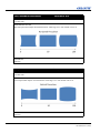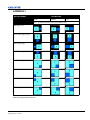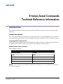
1
E Series Serial Commands
Technical Reference Information
INTRODUCTION
This document describes the serial protocol, consisting of ASCII text messages, used to control the E Series
projectors.
CONNECTION AND USE
Once you have connected your computer to either the RS232 IN port or to the ETHERNET port on a projector,
you can remotely access projector controls and image setups, issue commands or queries, and receive replies.
Setting up RS232 communication
Connect the projector and host using a null standard cable with 9-pin female to the host, and 9-pin female to
the projector. Pin 2 connects to pin 3, pin 3 connects to pin 2 and pin 5 connects to pin 5.
RS232 Communication parameters
Supported RS232 settings:
PARAMETER
DATA
Baud Rate Default
115200
Parity
None
Data Bits
8
Stop Bits
1
Flow Control
None
NOTE: Use direct connections from laptops and desktops. Docking ports of certain laptops have had issues
with software upgrades
E Series Serial Commands Technical Reference Information
020-000372-05 Rev. 1 (5-2011)
1 of 47
MESSAGE FORMAT
1. For all commands, a space may be entered between the code and the number. Example (PXT50), without a
space, can also be entered as (PXT 50), with a space. Both are valid.
2. A modifier can be added to some commands to allow the value to be incremented or decremented, without
having to enter an absolute value. Modifier “n” goes to “next value” and modifier “p” goes to “previous
value”.
For example: The OVS Overscan command allows the values:
(OVS0) : OFF
(OVS1) : ZOOM
(OVS2) : CROP
If the current setting is “Off”, then after (OVS n) is processed, the value will be set to “Zoom”. If the
current setting is “Crop”, then after (OVS p) is processed, the value will be set to “Zoom”.
Messages can be one of three types:
• Set - A command to set a projector parameter at a specific level, such as changing the brightness.
• Request - A request for information, such as what is the current brightness setting.
• Reply - The projector returns the data in response to a request or as confirmation of a command.
All “remote control” information passes in and out of the projector as a simple text message consisting of a
three letter command code, an optional four letter subcode and any related data. Optional features (message
acknowledges) can be included. Regardless of message type or origin, all messages use the same basic format
outlined in Table 1 Message Formats.
Table 1 Message Formats
SOURCE
MESSAGE FORMAT
FUNCTION
EXAMPLES
From Controller
(Code Data)
SET (set contrast to 50)
(CON500) or (CON 500)
(Code+Subcode Data)
SET (set source 1 name to “VGA BOX
1”)
(SNS+SRC1 “VGA BOX
1”)
(Code ?)
REQUEST (what is current contrast?)
(CON?) or (CON ?)
(Code+Subcode ?)
REQUEST (what is lamp 1 hours?)
(LIF+LP1H?)
(Code Data)
REPLY (contrast is 50)
(CON!50)
(Code+Subcode Data)
REPLY (LMP 1 HOURS IS 534)
(LIF+LP1H!534)
From Controller
From Projector
BASIC MESSAGE STRUCTURE
The following component fields comprise a standard ASCII message. Optional fields, such as extra characters
for special modes, restrictions or added functionality, are shown in italics, with the exception of Notes.
• START AND END OF MESSAGE: Every message begins with the left “(“character and ends with the
right “)“character. NOTE: If the start character is received before an end character of the previous message,
the partial (previous) message is discarded.
• PREFIX CHARACTERS (OPTIONAL): For acknowledgement that the projector has responded, and/or
to maximize message integrity, insert a special character before the 3-character function code: # - Full
Acknowledgment, which will cause an echo of the message as a reply to be sent back from the projector
2 of 47
E Series Serial Commands Technical Reference Information
020-000372-05 Rev. 1 (5-2011)
when it has finished processing the message. Note that requesting an acknowledgement serves no purpose
when included in a request message, since the acknowledgement will be redundant to the actual reply from
the projector.
• FUNCTION CODE: The projector function you wish to work with, such as contrast, is represented by a
three-character ASCII code (A-Z, upper or lower case). This function code appears immediately after the
leading “(“that starts the message. In messages sent to the projector that do not have a subcode, a space
between the function code and the first parameter (or special character) is optional.
• +SUBCODE: The projector function you wish to work with may have one or more subcodes that will allow
you to select a specific source or subfunction. The subcode is represented by a four-character ASCII code
(A-Z, upper or lower case, and 0-9). This subcode appears immediately after the function code, with a “+”
character to separate the code and subcode. If there is no subcode, the “+” is also omitted. In messages sent to
the projector that do have a subcode, a space between the subcode and the first parameter (or special character) is optional.
• REQUEST/REPLY SYMBOLS: If the controller is requesting information from the projector, a “?” question mark appears directly after the function code. If the projector is replying, a “!” exclamation mark
appears directly after the function code. For set messages to the projector, neither of these characters appear
— data directly follows the code and subcode.
MESSAGE ERRORS
If a command cannot be performed (e.g. syntax error), you will receive a descriptive error indicating the
problem. For example: (ITP) - (65535 00000 ERR00005 "ITP: Too Few Parameters")
E Series Serial Commands Technical Reference Information
020-000372-05 Rev. 1 (5-2011)
3 of 47
TABLE OF CONTENTS
SIZE & POSITION COMMANDS .............................................................................................. 7
(SZP) SIZE PRESETS ........................................................................................................7
(OVS) OVER SCAN ..........................................................................................................7
(PXP) PIXEL PHASE ........................................................................................................7
(PXT) PIXEL TRACK .......................................................................................................8
(HOR) HORZ POSITION ..................................................................................................8
(VRT) VERT POSITION ...................................................................................................8
(WRP+HKST) HORZ KEYSTONE ..................................................................................9
(WRP+VKST) VERT KEYSTONE ...................................................................................9
(HPC) HORZONTAL PINCUSHION .............................................................................10
(VPC) VERTICAL PINCUSHION ..................................................................................10
(SIZ) DIGITAL ZOOM ....................................................................................................11
(DSH) DIGITAL HORZ SHIFT ......................................................................................11
(DSV) DIGITAL VERT SHIFT .......................................................................................12
(AIM) AUTO IMAGE ......................................................................................................12
IMAGE SETTING COMMANDS ............................................................................................. 13
(BRT) BRIGHTNESS ......................................................................................................13
(CON) CONTRAST .........................................................................................................13
(CSP) COLOR SPACE ....................................................................................................13
(DTL) DETAIL ................................................................................................................14
(CLR) COLOR .................................................................................................................14
(TNT) TINT ......................................................................................................................14
(NRD) NOISE REDUCTION ..........................................................................................15
(FTC) FLESH TONE CORRECTION .............................................................................15
(VBL) VIDEO BLACK LEVEL ......................................................................................15
(FMD) DETECT FILM ....................................................................................................16
(CLC) CLOSED CAPTIONS ...........................................................................................16
(ROG) RED GAIN ...........................................................................................................16
(GOG) GREEN GAIN ......................................................................................................17
(BOG) BLUE GAIN .........................................................................................................17
(ROO) RED OFFSET .......................................................................................................17
(GOO) GREEN OFFSET .................................................................................................17
(BOO) BLUE OFFSET ....................................................................................................18
(SYT) SYNC THRESHOLD ............................................................................................18
(GOR) RGB GAIN/OFFSET RESET ..............................................................................18
(PST) PICTURE SETTING .............................................................................................19
(DIM) DYNAMICBLACK ..............................................................................................19
(BGC) GAMMA CURVE ................................................................................................19
(BCL) BRILLIANTCOLOR ............................................................................................20
(WPK) WHITE PEAKING ..............................................................................................21
(CCI) COLOR TEMPERATURE ....................................................................................21
(EDG) EDGE ENHANCEMENT ....................................................................................21
(CWS) COLOR WHEEL SPEED ....................................................................................21
4 of 47
E Series Serial Commands Technical Reference Information
020-000372-05 Rev. 1 (5-2011)
CONFIGURATION COMMANDS ...........................................................................................22
(LOC) LOCAL SETTINGS ............................................................................................. 22
(FCS) FOCUS .................................................................................................................. 22
(LVO) LENS SHIFT VERTICAL ................................................................................... 23
(LHO) LENS SHIFT HORIZONTAL ............................................................................. 23
(LCB+LOCK) LOCK LENS MOTORS .......................................................................... 23
(LCB+HOME) LENS CENTER ...................................................................................... 23
(CEL) CEILING MOUNT SETTING ............................................................................. 24
(SOR) REAR PROJECTION ........................................................................................... 24
(MSH) MENU SHIFT HORIZONTAL ........................................................................... 24
(MSV) MENU SHIFT VERTICAL ................................................................................. 24
(MBE) SHOW MESSAGES ( MESSAGE BOX ENABLE) .......................................... 25
(OST) MENU TRANSPARENCY .................................................................................. 25
(SPS) SPLASH SCREEN SETUP ................................................................................... 25
(PIV) PIN PROTECT ...................................................................................................... 26
(PCG) CHANGE PIN ...................................................................................................... 26
(PWR+STBM) STANDBY MODE ................................................................................. 26
(APW) AUTO POWER ON ............................................................................................ 27
(ASH) AUTO SHUTDOWN ........................................................................................... 27
(SLP) SLEEP TIMER ...................................................................................................... 28
(HAT) HIGH ALTITUDE ............................................................................................... 28
(NET) NETWORK .......................................................................................................... 29
(BDR) SERIAL PORT BAUD RATE ............................................................................. 29
(SEC) SERIAL PORT ECHO .......................................................................................... 30
(VTT) 12V TRIGGER ..................................................................................................... 30
(HKS) HOT-KEY SETTINGS ........................................................................................ 30
LAMP COMMANDS ..................................................................................................................31
(LPM) LAMP POWER .................................................................................................... 31
(LOP) CURRENT LAMP ................................................................................................ 31
(WSP) WHISPER MODE ............................................................................................... 32
(LSF) LAMP AUTO SWITCH ........................................................................................ 32
(LIF) LAMP INFO ........................................................................................................... 33
(LPL) LAMP LIFE WARNING ...................................................................................... 33
(LPC) RESET LAMP HOURS ........................................................................................ 33
INPUT SWITCHING & PIP COMMANDS .............................................................................34
(SIN) INPUT/SOURCE CHANGE FUNCTIONS .......................................................... 34
(PIP) PIP/PBP FUNCTIONS ........................................................................................... 34
(PPS) PIP/PBP SWAP ..................................................................................................... 34
(PHS) PIP/PBP SIZE ....................................................................................................... 35
(PPP) PIP/PBP LAYOUT ................................................................................................ 35
(TMG) TIMING DETECT MODE .................................................................................. 35
(MIF) MAIN(SINGLE) SOURCE INFO ........................................................................ 36
(SIF) SECONDARY SOURCE INFO ............................................................................. 36
(ESH) ENABLED MAIN SOURCE HOT KEY ............................................................. 37
(MHK) MAIN SOURCE HOT-KEY SETTINGS ........................................................... 37
(SKS) SOURCE KEY FUNCTION SETTING ............................................................... 37
E Series Serial Commands Technical Reference Information
020-000372-05 Rev. 1 (5-2011)
5 of 47
MISCELLANEOUS COMMANDS .......................................................................................... 38
(ITP) TEST PATTERN ....................................................................................................38
(SST) PROJECTOR STATUS .........................................................................................39
SERVICE COMMANDS ............................................................................................................ 40
(CWI) COLOR WHEEL INDEX SETTING ...................................................................40
(PIF) PROJECTOR INFO ................................................................................................40
(DEF) FACTORY DEFAULTS .......................................................................................40
(UID) ENTER SERVICE CODE .....................................................................................41
FUNCTIONS USED ONLY BY SERIAL COMMAND .......................................................... 42
(SIV) E SERIES SERIAL COMMAND VERSION ........................................................42
(LCE) LAST SERIAL COMMAND ERROR .................................................................42
(LSE) GET LAST SYSTEM ERROR ..............................................................................42
(PWR) POWER ON/OFF .................................................................................................43
(SNS) SOURCE NAME SETTING .................................................................................43
(KEY) KEY-CODE ENTRY SETTING ..........................................................................43
(SHU) SHUTTER ON/OFF CONTROL .........................................................................44
(OSD) OSD SHOW/HIDE ...............................................................................................44
APPENDIX-1 ............................................................................................................................... 45
PIP/PBP LAYOUT ...........................................................................................................45
APPENDIX-2 ............................................................................................................................... 46
IR REMOTE KEYCODES ..............................................................................................46
6 of 47
E Series Serial Commands Technical Reference Information
020-000372-05 Rev. 1 (5-2011)
SIZE & POSITION COMMANDS
(SZP) SIZE PRESETS
READ/WRITE: R/W
SUBCODE
<No Sub code>
Allows modifiers “n” and “p” for selecting “next” and “previous” values.
DESCRIPTION OF USE
Scales the input image to a set of predefined aspect ratios. Default value is ‘Auto’.
EXAMPLES:
(SZP0) : Auto
(SZP1) : Native
(SZP2) : 4:3
(SZP3) : LetterBox
(SZP4) : Full Size
(SZP5) : Full Width
(SZP6) : Full Height
(OVS) OVER SCAN
READ/WRITE: R/W
SUBCODE
<No Sub code>
Allows modifiers “n” and “p” for selecting “next” and “previous” values.
DESCRIPTION OF USE
Controls how edges of the input image are framed.
EXAMPLES:
(OVS0) : OFF
(OVS1) : ZOOM
(OVS2) : CROP
(PXP) PIXEL PHASE
READ/WRITE: R/W
SUBCODE
<No Sub code>
DESCRIPTION OF USE
Adjusts the phase of the pixel clock created for analog inputs in the range 0 to100. Default value is 50.
EXAMPLES:
(PXP50)
E Series Serial Commands Technical Reference Information
020-000372-05 Rev. 1 (5-2011)
7 of 47
(PXT) PIXEL TRACK
READ/WRITE: R/W
SUBCODE
<No Sub code>
DESCRIPTION OF USE
Adjusts the number of pixel clocks per horizontal sync in the range 0-100. Default value is 50.
EXAMPLES:
(PXT50)
(HOR) HORZ POSITION
READ/WRITE: R/W
SUBCODE
<No Sub code>
DESCRIPTION OF USE
Moves the starting point of the input capture. When applying this function, some of the active area
will be blanked. Increasing the value moves the active image to the right. Valid range is 0 to 100.
Default value is 50.
EXAMPLES:
(HOR50)
(VRT) VERT POSITION
READ/WRITE: R/W
SUBCODE
<No Sub code>
DESCRIPTION OF USE
Moves the starting point of the input capture. When applying this function, some of the active area
will be blanked. Increasing the value moves the active region up. Valid range is 0 to 100. Default
value is 50.
EXAMPLES:
(VRT50)
8 of 47
E Series Serial Commands Technical Reference Information
020-000372-05 Rev. 1 (5-2011)
(WRP+HKST) HORZ KEYSTONE
READ/WRITE: R/W
SUBCODE
HKST
DESCRIPTION OF USE
Horizontal keystone : corrects the distortion created when the projected image is to the left or right of
the lens axis and increasing this value increases right keystoning:
Valid range is 0 to 100. Default value is 50.
EXAMPLES:
(WRP+HKST 50)
(WRP+VKST) VERT KEYSTONE
READ/WRITE: R/W
SUBCODE
VKST
DESCRIPTION OF USE
Vertical keystone corrects the distortion created when the projected image is above or below the lens
axis, and increasing this value increases positive keystoning:
Valid range is 0 to 100. Default value is 50.
EXAMPLES:
(WRP+VKST 50)
E Series Serial Commands Technical Reference Information
020-000372-05 Rev. 1 (5-2011)
9 of 47
(HPC) HORZONTAL PINCUSHION
READ/WRITE: R/W
SUBCODE
<No Sub code>
DESCRIPTION OF USE
Horizontal pincushion adjusts horizontal distortion. Valid range is 0 to 100. Default value is 50.
.
EXAMPLES:
(HPC50)
(VPC) VERTICAL PINCUSHION
READ/WRITE: R/W
SUBCODE
<No Sub code>
DESCRIPTION OF USE
Vertical pincushion adjusts vertical distortion. Valid range is 0 to 100. Default value is 50.
.
EXAMPLES:
(VPC50)
10 of 47
E Series Serial Commands Technical Reference Information
020-000372-05 Rev. 1 (5-2011)
(SIZ) DIGITAL ZOOM
READ/WRITE: R/W
SUBCODE
<No Sub code>
DESCRIPTION OF USE
Valid range is 0-100:
100 for normal (unchanged) display area size - if there are any black borders around edges of the
display area, they are as small as possible (Default).
0 for display area reduced as small as possible – there will be large black borders around the edges of
the displayed image.
EXAMPLES:
(SIZ100)
(DSH) DIGITAL HORZ SHIFT
READ/WRITE: R/W
SUBCODE
<No Sub code>
DESCRIPTION OF USE
Valid range for horizontal position is 0 to 100:
At 0 the display area is moved as far as possible to the left, at 50 the display area is horizontally
centered, and at 100 the display area is moved as far as possible to the right. The image must be
“zoomed out” (Digital Zoom) before this function can be used. “Digital Horz Shift” will be disabled
if Digital Zoom has not been applied. Default value is 50.
EXAMPLES:
(DSH50)
E Series Serial Commands Technical Reference Information
020-000372-05 Rev. 1 (5-2011)
11 of 47
(DSV) DIGITAL VERT SHIFT
READ/WRITE: WRITE ONLY
SUBCODE
<No Sub code>
DESCRIPTION OF USE
Valid range for vertical position is 0 to 100:
At 0 the display area is moved as far as possible to the top, at 50 the display area is vertically centered,
and at 100 the display area is moved as far as possible to the bottom. The image must be “zoomed out”
(Digital Zoom) before this function can be used. “Digital Horz Shift” will be disabled if Digital Zoom
has not been applied. Default value is 50.
EXAMPLES:
(DSV50)
(AIM) AUTO IMAGE
READ/WRITE: WRITE ONLY
SUBCODE
<No Sub code>
DESCRIPTION OF USE
Forces the projector to reacquire and lock to the input signal. This is useful when signal quality is
marginal.
EXAMPLES:
(AIM1)
12 of 47
E Series Serial Commands Technical Reference Information
020-000372-05 Rev. 1 (5-2011)
IMAGE SETTING COMMANDS
(BRT) BRIGHTNESS
READ/WRITE: R/W
SUBCODE
<No Sub code>
DESCRIPTION OF USE
Adjusts the overall black level of the projected image by applying an offset to the input image. Valid
range is 0 to 100. Default value is 50.
EXAMPLES:
(BRT50)
(CON) CONTRAST
READ/WRITE: R/W
SUBCODE
<No Sub code>
DESCRIPTION OF USE
Adjusts the overall white level of the projected image by applying a gain to the input image. Valid
range is 0 to 100. Default value is 50.
EXAMPLES:
(CON50)
(CSP) COLOR SPACE
READ/WRITE: R/W
SUBCODE
<No Sub code>
Allows modifiers “n” and “p” for selecting “next” and “previous” values.
DESCRIPTION OF USE
Sets the color space of the input signal. Default value is ‘Auto’.
EXAMPLES:
(CSP0) : RGB
(CSP1) : REC709
(CSP2) : REC601
(CSP3) : RGB Video
(CSP4) : Auto
E Series Serial Commands Technical Reference Information
020-000372-05 Rev. 1 (5-2011)
13 of 47
(DTL) DETAIL
READ/WRITE: R/W
SUBCODE
<No Sub code>
Allows modifiers “n” and “p” for selecting “next” and “previous” values.
DESCRIPTION OF USE
Applies a predefined sharpness setting to the current input signal. This adjusts the overall detail of the
projected image. Default value is ‘Normal’.
EXAMPLES:
(DTL0) : Maximum
(DTL1) : High
(DTL2) : Normal
(DTL3) : Low
(DTL4) : Minimum
(CLR) COLOR
READ/WRITE: R/W
SUBCODE
<No Sub code>
DESCRIPTION OF USE
Adjusts the color saturation of analog video sources. Valid range is 0 to 100. Default value is 50.
EXAMPLES:
(CLR50)
(TNT) TINT
READ/WRITE: R/W
SUBCODE
<No Sub code>
DESCRIPTION OF USE
Adjusts the red/green balance of analog video NTSC sources. Valid range is 0 to 100. Default value is
50.
EXAMPLES:
(TNT50)
14 of 47
E Series Serial Commands Technical Reference Information
020-000372-05 Rev. 1 (5-2011)
(NRD) NOISE REDUCTION
READ/WRITE: R/W
SUBCODE
<No Sub code>
DESCRIPTION OF USE
Reduces temporal and/or spatial noise in the image. Valid range is 0 to 100. Default value is 0.
EXAMPLES:
(NRD50)
(FTC) FLESH TONE CORRECTION
READ/WRITE: R/W
SUBCODE
<No Sub code>
DESCRIPTION OF USE
Controls the amount of flesh tone correction applied to the image. Valid range is 0 to 100. Default
value is 0.
EXAMPLES:
(FTC50)
(VBL) VIDEO BLACK LEVEL
READ/WRITE: R/W
SUBCODE
<No Sub code>
Allows modifiers “n” and “p” for selecting “next” and “previous” values
DESCRIPTION OF USE
When ‘On’, the projector will analyze the current input image and calculate an offset value which is
then added to the Analog to Digital converter black level value. This ensures optimum black level for
each analog source.
EXAMPLES:
(VBL0) : IRE off.
(VBL1) : IRE on.
E Series Serial Commands Technical Reference Information
020-000372-05 Rev. 1 (5-2011)
15 of 47
(FMD) DETECT FILM
READ/WRITE: R/W
SUBCODE
<No Sub code>
Allows modifiers “n” and “p” for selecting “next” and “previous” values.
DESCRIPTION OF USE
Controls film mode detection. This determines whether the original source of the input video was
film(progressive) or video (interlaced), by analyzing motion in the video. This information allows the
projector to correctly display fields from interlaced sources. Default value is ‘On’.
EXAMPLES:
(FMD0) : Detect film OFF
(FMD1) : Detect film ON
(CLC) CLOSED CAPTIONS
READ/WRITE: R/W
SUBCODE
<No Sub code>
Allows modifiers “n” and “p” for selecting “next” and “previous” values.
DESCRIPTION OF USE
Controls closed caption display while audio is muted. Default value is ‘Off’.
EXAMPLES:
(CLC0) : off
(CLC1) : CC1
(CLC2) : CC2
(ROG) RED GAIN
READ/WRITE: R/W
SUBCODE
<No Sub code>
DESCRIPTION OF USE
Valid range is 0 to 100. Default value is 50.
EXAMPLES:
(ROG50)
16 of 47
E Series Serial Commands Technical Reference Information
020-000372-05 Rev. 1 (5-2011)
(GOG) GREEN GAIN
READ/WRITE: R/W
SUBCODE
<No Sub code>
DESCRIPTION OF USE
Valid range is 0 to 100. Default value is 50.
EXAMPLES:
(GOG50)
(BOG) BLUE GAIN
READ/WRITE: R/W
SUBCODE
<No Sub code>
DESCRIPTION OF USE
Valid range is 0 to 100. Default value is 50.
EXAMPLES:
(BOG50)
(ROO) RED OFFSET
READ/WRITE: R/W
SUBCODE
<No Sub code>
DESCRIPTION OF USE
Valid range is 0 to 100. Default value is 50.
EXAMPLES:
(ROO50)
(GOO) GREEN OFFSET
READ/WRITE: R/W
SUBCODE
<No Sub code>
DESCRIPTION OF USE
Valid range is 0 to 100. Default value is 50.
EXAMPLES:
(GOO50)
E Series Serial Commands Technical Reference Information
020-000372-05 Rev. 1 (5-2011)
17 of 47
(BOO) BLUE OFFSET
READ/WRITE: R/W
SUBCODE
<No Sub code>
DESCRIPTION OF USE
Valid range is 0 to 100. Default value is 50.
EXAMPLES:
(BOO50)
(SYT) SYNC THRESHOLD
READ/WRITE: R/W
SUBCODE
<No Sub code>
DESCRIPTION OF USE
Adjusts the sync threshold for sync-on-green (SOG) signals. This controls the voltage at which a
negative pulse is determined to be a sync instead of active video. The setting is needed anytime the
active video source places its sync on the green/luma channel. Valid range is 0 to 100. Default is 50.
EXAMPLES:
(SYT50)
(GOR) RGB GAIN/OFFSET RESET
READ/WRITE: R/W
SUBCODE
<No Sub code>
DESCRIPTION OF USE
Reset the Red, Green and Blue gain and offset values.
EXAMPLES:
(GOR1): Reset RGB Gain/Offset settings.
18 of 47
E Series Serial Commands Technical Reference Information
020-000372-05 Rev. 1 (5-2011)
(PST) PICTURE SETTING
READ/WRITE: R/W
SUBCODE
<No Sub code>: Set picture setting
USER : Store currentl settings to User Mode. Allows modifiers “n” and “p” for selecting “next” and
“previous” values.
DESCRIPTION OF USE
Changing this setting updates values of picture-related settings (for the current source only) to a set of
predefined values.
EXAMPLES:
(PST0) : Presentation
(PST1) : Video
(PST2) : Bright
(PST3) : Whiteboard
(PST4) : Blackboard
(PST5) : Beige Wall
(PST6) : User
(PST+USER1) : Store currently settings to User Mode.
(DIM) DYNAMICBLACK
READ/WRITE: R/W
SUBCODE
<No Sub code>
Allows modifiers “n” and “p” for selecting “next” and “previous” values
DESCRIPTION OF USE
When switched ‘On’, the aperture will constantly adjust based on the amount of black in the current
scene.
EXAMPLES:
(DIM0) : DynamicBlack off.
(DIM1) : DynamicBlack on.
(BGC) GAMMA CURVE
READ/WRITE: R/W
SUBCODE
<No Sub code>
Allows modifiers “n” and “p” for selecting “next” and “previous” values.
DESCRIPTION OF USE
Selects gamma correction curve.
EXAMPLES:
(BGC0) : Video
(BGC1) : Film
(BGC2) : Bright
(BGC3) : CRT
E Series Serial Commands Technical Reference Information
020-000372-05 Rev. 1 (5-2011)
19 of 47
(BCL) BRILLIANTCOLOR
READ/WRITE: R/W
SUBCODE
<No Sub code>
DESCRIPTION OF USE
Increases image brightness but reduces overall color accuracy.
EXAMPLES:
(BCL0) : Normal Look
(BCL1) : Bright Look Want to be able to adjust from 1 to 10, and 0 will be off or Normal look
Coretronics comments: Technically, we could use HSG function by adjusting “White gain” and it can
set 10 level or 5 level depends on request. But we still need to have more discussion to make sure
what kind of performance need to achieve.
(WPK) WHITE PEAKING
READ/WRITE: R/W
SUBCODE
<No Sub code>
DESCRIPTION OF USE
Adjusts the amount of white processing through the data path.
EXAMPLES:
(WPK50)
(CCI) COLOR TEMPERATURE
READ/WRITE: R/W
SUBCODE
<No Sub code>
Allows modifiers “n” and “p” for selecting “next” and “previous” values.
DESCRIPTION OF USE
Applies a predefined color temperature to the input signal
EXAMPLES:
(CCI0) : Warmest
(CCI1) : Warm
(CCI2) : Cool
(CCI3) : Bright
20 of 47
E Series Serial Commands Technical Reference Information
020-000372-05 Rev. 1 (5-2011)
(EDG) EDGE ENHANCEMENT
READ/WRITE: R/W
SUBCODE
<No Sub code>
Allows modifiers “n” and “p” for selecting “next” and “previous” values
DESCRIPTION OF USE
Apply edge enhancement.
EXAMPLES:
(EDG0): off.
(EDG1): normal.
(EDG2): Maximum.
(CWS) COLOR WHEEL SPEED
READ/WRITE: R/W
SUBCODE
<No Sub code>
Allows modifiers “n” and “p” for selecting “next” and “previous” values.
DESCRIPTION OF USE
Setting Color Wheel speed to 2 x or 3x setting.
EXAMPLES:
(CWS0) : Set Color Wheel speed to 2x setting.
(CWS1) : Set Color Wheel speed to 3x setting.
E Series Serial Commands Technical Reference Information
020-000372-05 Rev. 1 (5-2011)
21 of 47
CONFIGURATION COMMANDS
(LOC) LOCAL SETTINGS
READ/WRITE: R/W
SUBCODE
LANG – Language
Allows modifiers “n” and “p” for selecting “next” and “previous” values.
DESCRIPTION OF USE
Controls which language to display in the OSD.
EXAMPLES:
(LOC+LANG 0) – set the language to English
(LOC+LANG 1) – set the language to Chinese
(LOC+LANG 2) – set the language to French
(LOC+LANG 3) – set the language to German
(LOC+LANG 4) – set the language to Italian
(LOC+LANG 5) – set the language to Japanese
(LOC+LANG 6) – set the language to Korean
(LOC+LANG 7) – set the language to Russian
(LOC+LANG 8) – set the language to Spanish
(FCS) FOCUS
(ZOM) ZOOM
READ/WRITE: WRITE ONLY
SUBCODE
<No Sub code>
Allows modifiers “n” and “p” for selecting “next” and “previous” values.
DESCRIPTION OF USE
Adjust the lens focus or zoom offset.
Or use modifier “n” to increase value by 1 or “p” to decrease value by 1.
EXAMPLES:
(FCS n) to increase focus by 1
(ZOM p) to decrease zoom by 1
22 of 47
E Series Serial Commands Technical Reference Information
020-000372-05 Rev. 1 (5-2011)
(LVO) LENS SHIFT VERTICAL
(LHO) LENS SHIFT HORIZONTAL
READ/WRITE: WRITE ONLY
SUBCODE
<No Sub code>
Allows modifiers “n” and “p” for selecting “next” and “previous” values.
DESCRIPTION OF USE
Adjust the lens vertical or horizontal offset.
Or use modifier “n” to increase value by 1 or “p” to decrease value by 1.
EXAMPLES:
(LVO n) to increase vertical position by 1
(LHO p) to decrease horizontal position by 1
(LCB+LOCK) LOCK LENS MOTORS
READ/WRITE: R/W
SUBCODE
LOCK: Lock the Zoom, Focus, Horizontal and Vertical Lens motors.
Allows modifiers “n” and “p” for selecting “next” and “previous” values.
DESCRIPTION OF USE
Select the function to prevent all lens motors from moving. It will effectively lock out any changes
and, override all other lens features. This is useful to prevent lens position changes. Default value is
‘Allow’ movement.
EXAMPLES:
(LCB+LOCK0) : Allow
(LCB+LOCK1) : Locked
(LCB+HOME) LENS CENTER
READ/WRITE: WRITE ONLY
SUBCODE
HOME: Move to center
DESCRIPTION OF USE
Calibrates the lens and then returns the lens to horizontal and vertical home position. Focus and Zoom
are not affected.
EXAMPLES:
(LCB+HOME1)
E Series Serial Commands Technical Reference Information
020-000372-05 Rev. 1 (5-2011)
23 of 47
(CEL) CEILING MOUNT SETTING
READ/WRITE: R/W
SUBCODE
<No Sub code>
DESCRIPTION OF USE
Change the orientation of the image for ceiling-mounted projectors. When set to ‘On’, the image will
be turned upside-down.
EXAMPLES:
(CEL0) : Ceiling mount off.
(CEL1) : Ceiling mount on.
(CEL2) : Auto. (The projector uses a G-sensor to detect the orientation of the projector)
(SOR) REAR PROJECTION
READ/WRITE: R/W
SUBCODE
<No Sub code>
DESCRIPTION OF USE
Reverse the image so tha the image can be projected from behind a transluscent screen.
EXAMPLES:
(SOR0) : Off.
(SOR1) : On.
(MSH) MENU SHIFT HORIZONTAL
(MSV) MENU SHIFT VERTICAL
READ/WRITE: R/W
SUBCODE
<No Sub code>
DESCRIPTION OF USE
Adjusts the location of on-screen menus and messages. Valid range is 0 to 100. Default value is 0.
EXAMPLES:
(MSH0) - Set horizontal position of menu to left position.
(MSV50) - Set vertical position of menu to center position.
24 of 47
E Series Serial Commands Technical Reference Information
020-000372-05 Rev. 1 (5-2011)
(MBE) SHOW MESSAGES ( MESSAGE
BOX ENABLE)
READ/WRITE: R/W
SUBCODE
USER
Allows modifiers “n” and “p” for selecting “next” and “previous” values.
DESCRIPTION OF USE
Controls whether or not the projector displays OSD messages (e.g. source name when searching or
changing source, slider when changing keystone, etc.). Default value is ‘On’.
EXAMPLES:
(MBE+USER0) : OFF
(MBE+USER1) : ON
(OST) MENU TRANSPARENCY
READ/WRITE: R/W
SUBCODE
<No Sub code>
DESCRIPTION OF USE
Controls amount of transparency of the OSD (for menu and messages). Valid range is 0 to 90. Default
value is 0 (not transparent).
EXAMPLES:
(OST0)
(SPS) SPLASH SCREEN SETUP
READ/WRITE: R/W
SUBCODE
SLCT
Allows modifiers “n” and “p” for selecting “next” and “previous” values.
DESCRIPTION OF USE
Choose which splash screen is to be used when no image or test pattern is displayed. Default value is
‘Factory Logo’.
EXAMPLES:
(SPS+SLCT0) : Factory Logo
(SPS+SLCT 1) : Blue
(SPS+SLCT 2) : Black
(SPS+SLCT 3) : White
E Series Serial Commands Technical Reference Information
020-000372-05 Rev. 1 (5-2011)
25 of 47
(PIV) PIN PROTECT
READ/WRITE: R/W
SUBCODE
<No Sub code>
DESCRIPTION OF USE
The PIN (personal Identification Number) allows you to password protect the projector. Once the PIN
feature is enabled, the PIN must be entered before an image can be projected.
EXAMPLES:
(PIV”XXXXX”) : if XXXXX Password is correct, the Pin protect function Toggles.
Note: XXXXX is number from 0 to 9
(PCG) CHANGE PIN
READ/WRITE: R/W
SUBCODE
<No Sub code>
DESCRIPTION OF USE
Change the PIN (Personal Identification Number). Default PIN is ‘12345’.
EXAMPLES:
(PCG”OOOOO,NNNNN”)
OOOOO means old password.
NNNNN means new password.
Note: XXXXX is number from 0 to 9
(PWR+STBM) STANDBY MODE
READ/WRITE: R/W
SUBCODE
STBM
Allows modifiers “n” and “p” for selecting “next” and “previous” values.
DESCRIPTION OF USE
Standby Modes are:
• 1W Mode: when this mode has been selected, the power consumption is under 1W (to meet EUP
regulation) and only the Keypad gets power. The system cannot power on via “UART/WEB/
USB”.
•Communication Mode: when this mode has been selected, the power consumption is approximately
20W, and both the Keypad and processor are powered. The system can power on via “UART/
WEB/USB”.
EXAMPLES:
(PWR+STBM0) : 1W mode
(PWR+STBM1) : Communication.
26 of 47
E Series Serial Commands Technical Reference Information
020-000372-05 Rev. 1 (5-2011)
(APW) AUTO POWER ON
READ/WRITE: R/W
SUBCODE
<No Sub code>
Allows modifiers “n” and “p” for selecting “next” and “previous” values.
DESCRIPTION OF USE
Enables and disables the projector’s automatic power on (allows the projector to be turned on using a
wall switch). When this mode been selected, the system will power on automatically and skip standby
mode when AC power is applied. Default value is ‘Off’.
EXAMPLES:
(APW0) : OFF
(APW1) : ON
(ASH) AUTO SHUTDOWN
READ/WRITE: R/W
SUBCODE
<No Sub code>
Allows modifiers “n” and “p” for selecting “next” and “previous” values.
DESCRIPTION OF USE
If the projector is in the Search state for longer than the set time wothout detecting an active signal, it
automatically powers down to ‘Standby Mode’.
EXAMPLES:
Default value is Off/Never
(ASH0) turns off auto shutdown mode(same as never)
(ASH1) 5 MIN
(ASH2) 10 MIN
(ASH3) 15 MIN
(ASH4) 20 MIN
(ASH5) 25 MIN
(ASH6) 30 MIN
E Series Serial Commands Technical Reference Information
020-000372-05 Rev. 1 (5-2011)
27 of 47
(SLP) SLEEP TIMER
READ/WRITE: R/W
SUBCODE
<No Sub code> enables or disables sleep mode.
Allows modifiers “n” and “p” for selecting “next” and “previous” values.
DESCRIPTION OF USE
Allows the projector to automatically power off after it has been on for a specified amount of time.
Timer starts when projector is powered on (or when sleep timer auto power off is canceled). Auto
power off occurs whether or not a source is being displayed.
EXAMPLES:
(SLP0) : OFF.
(SLP1) : 2 Hrs.
(SLP2) : 4 Hrs.
(SLP3) : 6 Hrs.
Default value is Off/Never
(HAT) HIGH ALTITUDE
READ/WRITE: R/W
SUBCODE
<No Sub code>
Allows modifiers “n” and “p” for selecting “next” and “previous” values
DESCRIPTION OF USE
Modify the fan speeds for high altitude.
EXAMPLES:
(HAT0): High Altitude off.
(HAT1): High Altitude on.
28 of 47
E Series Serial Commands Technical Reference Information
020-000372-05 Rev. 1 (5-2011)
(NET) NETWORK
READ/WRITE: R/W
SUBCODE
DHCP - Turn DHCP On/Off.
ETH0 - IP address
SUB0 - Subnet mask
GATE - Default gateway
HOST – Projector name
MAC0 - MAC Address
SHOW - Show Network Messages - Turn Messages On/Off.
RSTR - Restart network
RSET - Network Factory Reset
DESCRIPTION OF USE
Modify the network settings or return network settings back to their factory default values.
EXAMPLES:
(NET+DHCP0)
(NET+HOST”DWU670-E”)
(NET+MAC0”00:E0:47:01:02:3C”)
(NET+SHOW1)
(NET+ETH0”192.168.000.001”)
(NET+RSTR1)
(NET+SUB0”255.255.255.000”)
(BDR) SERIAL PORT BAUD RATE
READ/WRITE: R/W
SUBCODE
<No Sub code>
Allows modifiers “n” and “p” for selecting “next” and “previous” values
DESCRIPTION OF USE
Selects the serial port baud rate. Default value is ‘115200’.
EXAMPLES:
(BDR0) : 2400.
(BDR1) : 4800.
(BDR2) : 9600.
(BDR3) : 14400
(BDR4) : 19200.
(BDR5) : 38400.
(BDR6) : 57600.
(BDR7) : 115200.
E Series Serial Commands Technical Reference Information
020-000372-05 Rev. 1 (5-2011)
29 of 47
(SEC) SERIAL PORT ECHO
READ/WRITE: R/W
SUBCODE
<No Sub code>
Allows modifiers “n” and “p” for selecting “next” and “previous” values
DESCRIPTION OF USE
Controls whether the serial port echoes characters. Default value is ‘Off’.
EXAMPLES:
(SEC0) : OFF.
(SEC1) : ON
(VTT) 12V TRIGGER
READ/WRITE: R/W
SUBCODE
<No Sub code>
Allows modifiers “n” and “p” for selecting “next” and “previous” values
DESCRIPTION OF USE
The 12V trigger is an interface that is used for electrical projector screens. The screen is lowered or
raised automatically when the projector is switched ‘On/Off’.
EXAMPLES:
(VTT0): 12V Trigger off.
(VTT1): 12V Trigger on.
(HKS) HOT-KEY SETTINGS
READ/WRITE: R/W
SUBCODE
<No Sub code>
Allows modifiers “n” and “p” for selecting “next” and “previous” values
DESCRIPTION OF USE
Assign a different function to the ‘Hot-key’ on the IR remote. Choose a function that does not have a
dedicated button, allowing you to quickly and easily use that chosen function.
EXAMPLES:
(HKS0) : Blank Screen.
(HKS1) : Aspect Ratio.
(HKS2) : Freeze Screen.
(HKS3) : Projector Info.
(HKS4) : Overscan
(HKS5) : Closed Captions.
30 of 47
E Series Serial Commands Technical Reference Information
020-000372-05 Rev. 1 (5-2011)
LAMP COMMANDS
(LPM) LAMP POWER
READ/WRITE: R/W
SUBCODE
<No Sub code>NO SUB CODE>
DESCRIPTION OF USE
Set the lamp power. Default value is 330W.
EXAMPLES:
(LPM0) : 280w
(LPM1) : 285w
(LPM2) : .290w
(LPM3) :295w
(LPM4) : 300w
(LPM5) :305w
(LPM6) : 310w
(LPM7) :315w
(LPM8) : 320w.
(LPM9) :325w
(LPM10) : 330w
(LOP) CURRENT LAMP
READ/WRITE: R/W
SUBCODE
<No Sub code>
Allows modifiers “n” and “p” for selecting “next” and “previous” values
DESCRIPTION OF USE
Controls which lamp(s) are in use.
EXAMPLES:
(LOP1) : Only Lamp 1 lit.
(LOP2) : Only Lamp 2 lit.
(LOP3) : Both Lamps lit.
E Series Serial Commands Technical Reference Information
020-000372-05 Rev. 1 (5-2011)
31 of 47
(WSP) WHISPER MODE
READ/WRITE: R/W
SUBCODE
<No Sub code>
Allows modifiers “n” and “p” for selecting “next” and “previous” values
DESCRIPTION OF USE
Switch to ‘Whisper Mode’. This will switch the projector to the quietest possible mode. Lamp power
will be dropped to the minimum. This mode is not compatible with ‘High Altitude Mode’.
EXAMPLES:
(WSP0): Off.
(WSP1): Lamp1.
(WSP2): Lamp2.
(WSP3): Auto.
(LSF) LAMP AUTO SWITCH
READ/WRITE: R/W
SUBCODE
<No Sub code>: Control when the projector switches between lamps.Allows modifiers “n” and “p”
for selecting “next” and “previous” values
TIME : Set number of hours for Lamp Auto Switch.
DESCRIPTION OF USE
Controls when the projector switches between lamps.
EXAMPLES:
(LSF0) : Only switch lamps if a lamp fails.
(LSF1) : Switch lamps every time the projector is powered on (also switch if a
lamp fails).
(LSF2) : Switch lamps after the current lamp has operated for the indicated
number of hours (also switch if a lamp fails).
(LSF+TIME120) : Set the Lamp Auto Switch number hours to be 120 when selected item is “After N
Hours”.
32 of 47
E Series Serial Commands Technical Reference Information
020-000372-05 Rev. 1 (5-2011)
(LIF) LAMP INFO
READ/WRITE: READ ONLY
SUBCODE
LP1H : Get Lamp 1 Hours
LP2H : Get Lamp 2 Hours
LPTH : Get Total Hours All Lamps
LP1R : Get Lamp 1 Reset times
LP2R : Get Lamp 2 Reset times
DESCRIPTION OF USE
Display current lamp hour usage.
EXAMPLES:
(LIF+LP1H?)
(LPL) LAMP LIFE WARNING
READ/WRITE: R/W
SUBCODE
<No Sub code>
DESCRIPTION OF USE
Set the number of lamp hours of usage at which a warning must be given. When that number of hours
is reached on either lamp, a warning message will be displayed at power on, indicating that the lamp
should be changed.
This is a user settable limit only, and does not guarantee any number of hours for lamp life. This
control has no bearing on lamp warranty and is not tied to actual lamp life in any way. The default is 0,
which means that the feature is off and no warning will be generated.
EXAMPLES:
(LPL1500)
(LPC) RESET LAMP HOURS
READ/WRITE: WRITE ONLY
SUBCODE
LMP1 : Reset Lamp1 Hours.
LMP2 : Reset Lamp2 Hours.
BOTH : Reset both Lamps hours.
DESCRIPTION OF USE
Reset Lamp hours for both or Lamp1 or Lamp2.
EXAMPLES:
(LPC+LMP11) : Reset Lamp 1 Hours.
(LPC+LAMP21) : Reset Lamp 2 Hours.
(LPC+BOTH1) : Reset both lamps hours.
E Series Serial Commands Technical Reference Information
020-000372-05 Rev. 1 (5-2011)
33 of 47
INPUT SWITCHING & PIP COMMANDS
(SIN) INPUT/SOURCE CHANGE
FUNCTIONS
READ/WRITE: R/W
SUBCODE
<No Sub code> select the input to be displayed in the Main image.
(MAIN #) : select the input to be displayed in the Main image.
(PIIP #) : select the input to be displayed in the PIP image.
DESCRIPTION OF USE
Change source directly.
EXAMPLES:
(SIN0) : Change source to VGA1.
(SIN1) : Change source to VGA2.
(SIN2) : Change source to RGBHV (5-wire BNC)
(SIN3) : Change source to HDMI 1.
(SIN4) : Change source to HDMI 2.
(SIN5) : Change source to Component Video.
(SIN6) : Change source to S-Video.
(SIN7) : Change source to Composite Video.
(SIN+MAIN1) : Set Main Source to be “VGA2”.
(SIN+PIIP0) : Set PIP Source to be “VGA1”.
(PIP) PIP/PBP FUNCTIONS
READ/WRITE: R/W
SUBCODE
<No Sub code>
DESCRIPTION OF USE
Enable or Disable PIP/PBP. Default value is ‘Disabled’.
EXAMPLES:
(PIP 0) : Disable PIP/PBP
(PIP 1) : Enable PIP/PBP
(PPS) PIP/PBP SWAP
READ/WRITE: WRITE ONLY
SUBCODE
<No Sub code>
DESCRIPTION OF USE
Swap MAIN and PIP sources.
EXAMPLES:
(PPS1) : Swap MAIN and PIP sources.
34 of 47
E Series Serial Commands Technical Reference Information
020-000372-05 Rev. 1 (5-2011)
(PHS) PIP/PBP SIZE
READ/WRITE: R/W
SUBCODE
<No Sub code>
DESCRIPTION OF USE
Select the PIP/PBP size.
EXAMPLES:
(PHS0) : Small size.
(PHS1) : Medium size.
(PHS2) : Large size.
NOTE:
Refer to Appendix 1.
(PPP) PIP/PBP LAYOUT
READ/WRITE: R/W
SUBCODE
<No Sub code>
DESCRIPTION OF USE
Set the location of the PIP/PBP image.
EXAMPLES:
(PPP0) : POP,Bigger Left.
(PPP1) : Over-Under, Bigger Upper.
(PPP2) : POP,Bigger Right.
(PPP3) : Over-Under, Bigger Lower.
(PPP4) : PIP-Bottom Right.
(PPP5) : PIP-Bottom Left.
(PPP6) : PIP-Top Left.
(PPP7) : PIP-Top Right.
NOTE:
Refer to Appendix 1.
(TMG) TIMING DETECT MODE
READ/WRITE: R/W
SUBCODE
<No Sub code>
Allows modifiers “n” and “p” for selecting “next” and “previous” values
DESCRIPTION OF USE
Select ‘Timing Detection Mode’ to be wide or normal.
EXAMPLES:
(TMG0) : Normal
(TMG1) : Wide
E Series Serial Commands Technical Reference Information
020-000372-05 Rev. 1 (5-2011)
35 of 47
(MIF) MAIN (SINGLE) SOURCE INFO
READ/WRITE: READ ONLY
SUBCODE
ACTS : Get Active Source
SGFT : Get Signal Format
APRT : Get Aspect Ratio.
RESL : Get Resolution.
VREF : Get Vert Refresh.
HREF : Get Horz Refresh.
PIXC : Get Pixel Clock.
SYNC : Get SYNC Type
CLSP : Get Color Space.
DESCRIPTION OF USE
Shows the setting of the current source of the main image.
EXAMPLES:
(MIF+RESL?) - Return the main image resolution.
(SIF) SECONDARY SOURCE INFO
READ/WRITE: READ ONLY
SUBCODE
ACTS : Get Active Source
SGFT : Get Signal Format
APRT : Get Aspect Ratio.
RESL : Get Resolution.
VREF : Get Vert Refresh.
HREF : Get Horz Refresh.
PIXC : Get Pixel Clock.
SYNC : Get SYNC Type
CLSP : Get Color Space.
DESCRIPTION OF USE
Show the settings of the current source in the PIP/PBP image. This is only valid when PIP/PBP is
enabled.
EXAMPLES:
(SIF+RESL?) - Return the resolution of the PIP Image.
36 of 47
E Series Serial Commands Technical Reference Information
020-000372-05 Rev. 1 (5-2011)
(ESH) ENABLED MAIN SOURCE HOT KEY
READ/WRITE: R/W
SUBCODE
<No Sub Code>
DESCRIPTION OF USE
Enabled the hot key(0,9) to select source directly.
EXAMPLES:
(ESH0) : ON
(ESH1) : OFF
(MHK) MAIN SOURCE HOT-KEY
SETTINGS
READ/WRITE: R/W
SUBCODE
VGA1 : Set a number key to be hot-key for VGA1.
VGA2 : Set a number key to be hot-key for VGA2
BNC1 : Set a number key to be hot-key for BNC
HDM1 : Set a number key to be hot-key for HDMI1
HDM2 : Set a number key to be hot-key for HDMI2
CON1 : Set a number key to be hot-key for Component
SVDO : Set a number key to be hot-key for S-Video
COPS : Set a number key to be hot-key for Composite
DESCRIPTION OF USE
Allows the assignment of a Hot-key to a particular source.
EXAMPLES:
(MHK+VGA18) : Set number 8 to be hot-key for VGA1.
(SKS) SOURCE KEY FUNCTION SETTING
READ/WRITE: READ ONLY
SUBCODE
<No Sub Code>
DESCRIPTION OF USE
Assign a different function to the source Hot-key. The default function is ‘List all sources’.
EXAMPLES:
Function of the key to:
(SKS0) : Change source.
(SKS1) : List all of Sources.
(SKS2) : Change source with Auto
E Series Serial Commands Technical Reference Information
020-000372-05 Rev. 1 (5-2011)
37 of 47
MISCELLANEOUS COMMANDS
(ITP) TEST PATTERN
READ/WRITE: R/W
SUBCODE
<No Sub code>
Allows modifiers “n” and “p” for selecting “next” and “previous” values
DESCRIPTION OF USE
Display a test Pattern. Some test patterns are only available when logged-in as a Service user. Note
that when switching away from the Grid or Color Bars test patterns, the switch may take up to 18
seconds as these are special non-standard test patterns.
EXAMPLES:
(ITP0) : OFF
(ITP1) : Grid
(ITP2) : White
(ITP3) : Black
(ITP4) : Checkerboard
(ITP5) Color bars
(ITP6) : Red(Service mode only)
(ITP7) : Green(Service mode only)
(ITP8) : Blue(Service mode only)
(ITP9) : Yellow(Service mode only)
(ITP10) : Magenta(Service mode only)
(ITP11) : Cyan(Service mode only)
38 of 47
E Series Serial Commands Technical Reference Information
020-000372-05 Rev. 1 (5-2011)
(SST) PROJECTOR STATUS
READ/WRITE: READ ONLY
SUBCODE
<No Sub code>
DESCRIPTION OF USE
Status query command.
EXAMPLES:
(SST?)
Returns a series of responses as below items.
(SST!000 "DWU670-E" "Model Name")
(SST!001 "UC100712345" "Serial Number")
(SST!002 "1920x1200" "Native Resolution")
(SST!003 "HDMI 1" "Main Input")
(SST!004 "Digital" "Main Signal Format")
(SST!005 "148.5MHz" "Main Pixel")
(SST!006 "Separate" "Main Sync Type")
(SST!007 "67.7kHz" "Main Horz Refresh")
(SST!008 "60.0Hz" "Main Vert Refresh")
(SST!009 "HDMI 2" "PIP / PBP Input")
(SST!010 "Digital" "PIP / PBP Signal Format")
(SST!011 "135.2MHz" "PIP / PBP Pixel Clock")
(SST!012 "Separate" "PIP / PBP Sync Type")
(SST!013 "62.7kHz" "PIP / PBP Horz Refresh")
(SST!014 "60.0Hz" "PIP / PBP Vert Refresh")
(SST!015 "330 W" "Lamp Power Setting")
(SST!016 "Lamp 2" "Current Lamp")
(SST!017 "10 Hours" "Lamp 1 Hours")
(SST!018 "15 Hours" "Lamp 2 Hours")
(SST!019 "1W Mode" "Standby Mode")
(SST!020 "Allow" "Lens Lock Setting")
(SST!021 "192.168.1.10" "IP Address")
(SST!022 "On" "DHCP")
E Series Serial Commands Technical Reference Information
020-000372-05 Rev. 1 (5-2011)
39 of 47
SERVICE COMMANDS
(CWI) COLOR WHEEL INDEX SETTING
READ/WRITE: R/W
SUBCODE
SPX2 : Set up color wheel index for 2x speed.
SPX3 : Set up color wheel index for 3x speed.
DESCRIPTION OF USE
Color wheel index setting for 2x or 3x speed.
EXAMPLES:
(CWI+SPX2 26)
Note: This command only working with service mode is “on”.
(PIF) PROJECTOR INFO
READ/WRITE: READ ONLY
SUBCODE
MDLN : Get Model Name
SNUM : Get Serial-Number.
NERS : Get Native Resolution.
FWVS : Get FW version.
CFVS : Get Configuration.
BCVS : Get Boot Code Version.
DESCRIPTION OF USE
Displays read-only projector information. This function is only available when logged in as a
‘Service‘ user.
EXAMPLES:
(PIF+MDLN?)
(DEF) FACTORY DEFAULTS
READ/WRITE: WRITE ONLY
SUBCODE
<No sub-code>
DESCRIPTION OF USE
Returns all settings back to “new out of the box” configuration.
The number 111 must be sent with the command to prevent accidental use of this command. This
function is only available when logged in as a ‘Service’ user.
EXAMPLES:
(DEF 111)
40 of 47
E Series Serial Commands Technical Reference Information
020-000372-05 Rev. 1 (5-2011)
(UID) ENTER SERVICE CODE
READ/WRITE: WRITE ONLY
SUBCODE
<No Sub Code>
DESCRIPTION OF USE
Enter Service code to set the projector to ‘Service Mode’.
There are some service functions that will only work when in ‘Service Mode’.
The ‘Service Mode’ is turned ‘Off’ when the projector is powered ‘Off’. Format of the command is
(UID “username,password”).
EXAMPLES:
(UID”service,service”)
E Series Serial Commands Technical Reference Information
020-000372-05 Rev. 1 (5-2011)
41 of 47
FUNCTIONS USED ONLY BY SERIAL COMMAND
(SIV) E SERIES SERIAL COMMAND
VERSION
READ/WRITE: READ ONLY
SUBCODE
<No Sub Code>
DESCRIPTION OF USE
Get E Series serial command version.
EXAMPLES:
(SIV?)
(LCE) LAST SERIAL COMMAND ERROR
READ/WRITE: READ ONLY
SUBCODE
<No Sub Code>
DESCRIPTION OF USE
Get last serial command error.
EXAMPLES:
(LCE?)
(LSE) GET LAST SYSTEM ERROR
READ/WRITE: READ ONLY
SUBCODE
<No Sub Code>
DESCRIPTION OF USE
Get last system ERROR.(Lamp fail or fan fail or…….)
EXAMPLES:
LSE=1: The lamp did not strike after 5 attemps.
LSE=3: Lamp went out unexpectedly.
LSE=4: Fan failure.
LSE=5: Over temperature.
42 of 47
E Series Serial Commands Technical Reference Information
020-000372-05 Rev. 1 (5-2011)
(PWR) POWER ON/OFF
READ/WRITE: R/W
SUBCODE
<No Sub code>
Allows modifiers “n” and “p” for selecting “next” and “previous” values
DESCRIPTION OF USE
Power on/off projector. Power On will switch the projector from ‘Standby Mode’ to ‘Lamps On’.
Power Off will switch the projector back to ‘Standby Mode’.
EXAMPLES:
(PWR0) : Power off projector.
(PWR1) : Power on projector.
(SNS) SOURCE NAME SETTING
READ/WRITE: R/W
SUBCODE
SRC0 : Set new source name for VGA1 input.
SRC1 : Set new source name for VGA2 input.
SRC2 : Set new source name for BNC input.
SRC3 : Set new source name for HDMI1 input.
SRC4 : Set new source name for HDMI2 input.
SRC5 : Set new source name for Component input.
SRC6 : Set new source name for S-Video input.
SRC7 : Set new source name for Video input.
DESCRIPTION OF USE
Change the source name to a user-defined name.
EXAMPLES:
(SNS+SRC1”WUXGA”) : change the source name “VGA1” to “WUXGA”
(KEY) KEY-CODE ENTRY SETTING
READ/WRITE: WRITE ONLY
SUBCODE
<No Sub code>
DESCRIPTION OF USE
Used by manufacturing and service. Sends key codes to the projector, which should respond as if the
key was pressed on the keypad or remote.
See Sonic Infrared Key-code Specification(Appendix-2)
EXAMPLES:
(KEY17) : Send menu key to projector, the projector will show menu on OSD.
E Series Serial Commands Technical Reference Information
020-000372-05 Rev. 1 (5-2011)
43 of 47
(SHU) SHUTTER ON/OFF CONTROL
READ/WRITE: R/W
SUBCODE
<No Sub code>
Allows modifiers “n” and “p” for selecting “next” and “previous” values
DESCRIPTION OF USE
Open or close the shutter.
EXAMPLES:
(SHU0) : Open/Sutter off.
(SHU1) : Closed/Sutter on.<Displayed black screen>
(OSD) OSD SHOW/HIDE
READ/WRITE: R/W
SUBCODE
<No Sub code>
Allows modifiers “n” and “p” for selecting “next” and “previous” values
DESCRIPTION OF USE
Disable or enable the OSD. If the menu is displayed and the OSD is disabled, the OSD will disappear.
When it is enabled again, the menu will reappear at the same position that it was before being
disabled. This is unlike exiting from the menu on the OSD, which always returns to the first menu
position (item 1 in the Main menu).
EXAMPLES:
(OSD0): Hide.
(OSD1): Show.
44 of 47
E Series Serial Commands Technical Reference Information
020-000372-05 Rev. 1 (5-2011)
APPENDIX-1
PIP/PBP LAYOUT
PIP/PBP SIZE
Small
Medium
Large
Note: ‘P’ indicates primary source region (lighter color)
PBP Bigger Left
Over-Under, Bigger Upper
*
PBP, Bigger Right
*
Over-Under, Bigger Lower
*
PIP-Bottom Right
PIP-Bottom Left
PIP-Top Left
PIP-Top Right
*Both source regions are the same size.
E Series Serial Commands Technical Reference Information
020-000372-05 Rev. 1 (5-2011)
45 of 47
APPENDIX-2
IR REMOTE KEYCODES
The (KEY) command uses decimal values.
The Following are issues when using the (KEY) COMMAND:
1. Enter key works in the menu but in a drop down menu it will not select an item.
2. Exit key works in the menu but in a drop down menu it will exit out of that specific menu instead of just
the drop down menu.
46 of 47
REMOTE BUTTON
KEYCODE (DECIMAL)
POWER
0
INFO
66
AUTO
47
1
26
2
27
3
28
4
29
5
30
6
31
7
32
8
33
9
34
HELP
35
0
36
HOT KEY
65
MENU
19
TEST
1
SHUTTER
2
EXIT
20
UP
38
RIGHT
41
DOWN
42
LEFT
39
ENTER
40
INPUT
48
E Series Serial Commands Technical Reference Information
020-000372-05 Rev. 1 (5-2011)
REMOTE BUTTON
KEYCODE (DECIMAL)
OSD
49
CONTRAST
24
BRIGHT
25
FOCUS_LEFT
5
FOCUS_RIGHT
6
DISPLAY
64
GAMMA
23
ZOOM-
9
ZOOM+
10
KEYSTONE H-LEFT
69
KEYSTONE H-RIGHT
70
LENS H-LEFT
13
LENS H-RIGHT
14
KEYSTONE V-UP
71
KEYSTONE V-DOWN
72
LENS V-UP
18
LENS V-DOWN
17
PIP/POP
15
SIZE
67
LAYOUT
68
SWAP
43
E Series Serial Commands Technical Reference Information
020-000372-05 Rev. 1 (5-2011)
47 of 47