1
DATA PROJECTOR
V-1080/V-807
User’s Manual
Q
ME UIC
NU K
AU
TO
CE
UR
PO
WE
R
SO
ME
NU
S
PO
WE
R
AT
U
ST
VO
L
VKST
N
N
ST
HK
EL
NC
CA
Z
OO
M
EN
TE
R
AU
MEN
U
AS
QU
IC
PE
YC
S-V
VID
E
TO
CT
K
IDE
r
PIP
M
EZ
bP
B
AL
FR
E
r
YP
RG
O
DIG
IT
bC
O
OF
UT
E
PO
E
F
WE
R
ON
IMPORTANT
Digital Light Processing, DLP, Digital Micromirror Device and DMD are all trademarks of Texas Instruments.
Windows 98, Windows 95, and Windows 3.1 are registered trademarks in the United States and other
countries of Microsoft Corporation.
IBM is a registered trademark of International Business Machines Corporation.
Macintosh and MAC are trademarks of Apple Computer Inc.
Other names of companies and products mentioned are trademarks and registered trade-marks of
the respective companies. TM , ® and © marks are not used in this document.
IMPORTANT SAFETY INFORMATION
Precautions
Please read this manual carefully before using your PLUS V-1080 / V-807 Data Projector and
keep the manual handy for future reference.
CAUTION
TO PREVENT SHOCK, DO NOT OPEN THE CABINET. NO USER-SERVICEABLE
PARTS INSIDE. REFER SERVICING TO QUALIFIED PLUS SERVICE PERSONNEL.
This symbol warns the user that uninsulated voltage within the unit may have
sufficient magnitude to cause electric shock. Therefore, it is dangerous to
make any kind of contact with any part inside of this unit.
This symbol alerts the user that important literature concerning the operation and maintenance of this unit has been included. Therefore, it should be
read carefully in order to avoid any problems.
The above cautions are given on the bottom of the product.
WARNING
TO PREVENT FIRE OR SHOCK, DO NOT EXPOSE THIS UNIT TO RAIN OR MOISTURE. DO NOT USE THIS UNIT’S GROUNDED PLUG WITH AN EXTENSION CORD
OR IN AN OUTLET UNLESS ALL THREE PRONGS CAN BE FULLY INSERTED. DO
NOT OPEN THE CABINET. THERE ARE HIGH-VOLTAGE COMPONENTS INSIDE. ALL
SERVICING MUST BE DONE BY QUALIFIED PLUS SERVICE PERSONNEL.
WARNING
This is a class A product. In a domestic environment this product may cause radio interference in which case the user may be required to take adequate measures.
RF Interference
WARNING
The Federal Communications Commission does not allow any modifications or changes
to the unit EXCEPT those specified by PLUS Technologies in this manual. Failure to
comply with this government regulation could void your right to operate this equipment.
This equipment has been tested and found to comply with the limits for a Class A digital
device, pursuant to Part 15 of the FCC Rules. These limits are designed to provide reasonable protection against harmful interference when the equipment is operated in a
commercial environment. This equipment generates, uses, and can radiate radio frequency energy and, if not installed and used in accordance with the instruction manual,
may cause harmful interference to radio communications. Operation of this equipment in
a residential area is likely to cause harmful interference in which case the user will be
required to correct the interference at his own expense.
E-2
IMPORTANT SAFETY INFORMATION
Important Safeguards
These safety instructions are to ensure the long life of the unit and to prevent fire and shock.
Please read them carefully and heed all warnings.
Installation
•
•
•
•
•
•
For best results, use the unit in a darkened room.
Place the unit on a flat, level surface in a dry area away from dust and moisture.
Do not place the unit in direct sunlight, near heaters or heat radiating appliances.
Exposure to direct sunlight, smoke or steam can harm internal components.
Handle the unit carefully. Dropping or jarring can damage internal components.
Do not place heavy objects on top of the unit.
Power Supply
• The unit is designed to operate on a power supply of 100 - 240 V 50/60 Hz AC. Ensure
that your power supply fits these requirements before attempting to use the unit.
• For PLUGGABLE EQUIPMENT, the socket-outlet shall be installed near the equipment
and shall be accessible.
• Handle the power cable carefully and avoid excessive bending. A damaged cord can
cause electric shock or fire.
• Disconnect the power cable (mains lead) from the power outlet after using the unit.
Before disconnecting the power cable, make sure that the POWER indicator lights in
amber (not blinking or in green).
Cleaning
• Disconnect the power cable (mains lead) from the unit.
• Clean the cabinet of the unit periodically with a damp cloth. If heavily soiled, use a mild
detergent. Never use strong detergents or solvents such as alcohol or thinner.
• Use a blower or lens paper to clean the lens, and be careful not to scratch or mar the
lens.
• Clean the ventilation slots and speaker grills on the unit periodically using a vacuum
cleaner. If accumulated dust blocks the ventilation slots, the unit will overheat, which may
cause the unit to malfunction.
Use a soft brush attachment when using the vacuum cleaner. Do not use a hard attachment, such as a crevice tool, to prevent the damage to the unit.
Lamp Replacement
• Be sure to replace the lamp when the Status indicator comes on. If you continue to use
the lamp after 1000 hours of usage, the lamp will turn off.
E-3
IMPORTANT SAFETY INFORMATION
Fire and Shock Precautions
• Ensure that there is sufficient ventilation and that vents are unobstructed to prevent the
buildup of heat inside the unit. Allow at least 10 cm (3 inches) of space between the unit
and walls.
• Prevent foreign objects such as paper clips and bits of paper from falling into the unit. Do
not attempt to retrieve any objects that fell into the unit. Do not insert any metal objects
such as a wire or screwdriver into the unit. If something should fall into the unit, immediately disconnect the power cable from the unit and have the object removed by a qualified PLUS service person.
• Do not place any liquids on top of the unit.
• Do not look into the lens while the unit is on. Serious damage to your eyes could
result.
Carrying around
When carrying the unit around, please use the carrying case that comes with it and, to protect
the lens from scratches, always shut the sliding lens cap. Also, do not subject the unit to
strong mechanical shock.
E-4
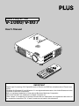
Major Features
Book-sized, lightweight (at about 0.9 kg/2.0 lbs) and small high-intensity mobile projector
DMDTM and the synergistic effects of our own optical design serve to improve the optical utilization
efficiency. The three light sources (RGB) required in color expression are reproduced with one DMDTM.
These factors have enabled a design that offers both high intensity and small size/lightweight features.
Sharp, clear picture
The absence of RGB color infidelity and the inconspicuous gaps between the individual dots permit
the display of small characters and diagrams with distinct clarity. An up-close look reveals the difference even more.
Beautiful reproduction of high-quality images from DVD
Faithful reproduction of color tones gives rise to the display of natural images. High-quality images
such as those from DVD and other sources bring out the display capabilities that are an essential
strength of the digital projector.
Heightened effectiveness with picture in picture
The video image is projected as a sub-picture within the personal computer picture. This expands the
usefulness of the projector even more.
Digital technology corrects the horizontal and vertical keystone distortion of the projected picture
New technology is used to correct the horizontal keystone distortion in addition to the regular keystone correction. This permits even simpler setup adjustments.
Connection permitted for personal computers equipped with DVI connectors
Inclusion of a DVI connector allows the input of analog RGB signals as well as digital RGB signals.
(The supplied conversion cable supports personal computers having a regular analog RGB connector. See the Table of Supported Frequencies on Page 69 for information about display resolution.)
E-5
Table of Contents
Preparation and Background Knowledge
IMPORTANT SAFETY INFORMATION ............................................................................ E-2
Major Features ................................................................................................................. E-5
Table of Contents ............................................................................................................. E-6
Checking the Supplied Accessories .............................................................................. E-8
Names of the Main Unit Parts ....................................................................................... E-10
Names of the Remote Control Parts ............................................................................ E-12
Preparing the Remote Control ...................................................................................... E-13
Button Battery Replacement ..................................................................................... E-13
Remote Control Range ............................................................................................. E-14
Setup and Projection
The Procedure Up to Projecting to the Screen ........................................................... E-15
Placement Guide
V-807 Screen Size and Projection Distance .............................................................. E-16
V-1080 Screen Size and Projection Distance ............................................................ E-17
Connecting Personal Computers and Video Equipment
Connections with PC Connectors
Personal Computers with a DVI Connector ......................................................... E-18
Personal Computers with a Mini D-Sub 15-Pin Connector ................................. E-19
To Output the External Output Signal of a Notebook Computer ......................... E-20
Connections with Video Connectors
Video Equipment with VIDEO Connectors .......................................................... E-21
Video Equipment with S-VIDEO Connectors ...................................................... E-21
Connections with Component Signals
When the Video Connectors are Y, Cb, and Cr Connectors ................................ E-22
When the Video Connectors are Y, Pb, and Pr Connectors ................................ E-22
Connections with Audio Connectors ......................................................................... E-23
Power Cable Connections and Switching the Power On/Off
Operating ................................................................................................................... E-24
Finishing .................................................................................................................... E-25
Adjustment of the Projection Screen
Projection Screen Position Adjustment ..................................................................... E-26
Making Adjustments with the Adjusters .............................................................. E-27
Focus Adjustment ...................................................................................................... E-27
General Operation
Input Selection ...............................................................................................................
Automatic Adjustment of Analog RGB ........................................................................
Selection of Aspect Ratio .............................................................................................
Projecting a Sub-Picture ...............................................................................................
Freezing a Moving Picture ............................................................................................
Cancelling Video and Audio Temporarily .....................................................................
Using the Quick Menu ...................................................................................................
Correcting Keystone Distortion of the Projection Screen .........................................
Enlargement of the Image and Video Movement ........................................................
Adjustment of the Volume .............................................................................................
E-6
E-28
E-29
E-30
E-31
E-31
E-31
E-32
E-34
E-35
E-36
Table of Contents
Menu Operations
Menu Operation Method ................................................................................................
Names and Functions of the Parts ............................................................................
Names and Functions of the Remote Control Buttons that Operate Via a Menu ......
Names and Functions of the Main Unit Buttons Used in Menu Operation ................
Names and Functions of Menu Screen Parts ............................................................
Performing Menu Operations ....................................................................................
Selecting Another Menu Name with Remote Control Operation ...............................
List of Item Names Offering Input Selection and Adjustments/Settings ....................
E-37
E-37
E-37
E-38
E-38
E-39
E-43
E-44
Adjustments and Settings
Picture
Brightness / Contrast / Color / Tint / Sharpness ........................................................
Picture Adjustment / Fine Picture / H Position / V Position ........................................
Reset .........................................................................................................................
Color
Gamma .....................................................................................................................
Color Temp. ...............................................................................................................
Color System .............................................................................................................
Color Space ..............................................................................................................
View
Aspect .......................................................................................................................
Filter ..........................................................................................................................
Projection ..................................................................................................................
Keystone ....................................................................................................................
Picture in Picture .......................................................................................................
Setup
Language ..................................................................................................................
Auto Source ...............................................................................................................
Auto Power Off ..........................................................................................................
On Screen .................................................................................................................
Menu Position ............................................................................................................
YPbPr ........................................................................................................................
Background ...............................................................................................................
White Balance ...........................................................................................................
E-55
E-55
E-56
E-56
E-57
E-57
E-57
E-58
Info.
Status ........................................................................................................................
Factory Default ..........................................................................................................
Lamp Timer Reset .....................................................................................................
Resolution / Frequency .............................................................................................
Lamp Timer ...............................................................................................................
E-59
E-59
E-59
E-60
E-60
E-46
E-47
E-48
E-49
E-49
E-50
E-50
E-51
E-52
E-52
E-53
E-54
Miscellaneous
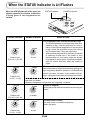
When the STATUS Indicator is Lit/Flashes ..................................................................
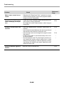
Troubleshooting .............................................................................................................
Cleaning .........................................................................................................................
Replacing the Lamp Cartridge .....................................................................................
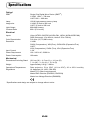
Specifications ................................................................................................................
Table of Supported Frequencies ..................................................................................
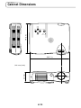
Cabinet Dimensions ......................................................................................................
E-7
E-61
E-63
E-65
E-66
E-69
E-70
E-71
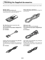
Checking the Supplied Accessories
Remove the main unit and the accessories from the box and check that the following items are included.
Remote control
(includes one button battery) [1]
This controls the projector. Please remove the transportation
insulation sheet at time of purchase. (See Page E-13.)
Power cable (1.8 m / 5.9 feet) [1]
This power cable supplies power to the unit. See Page E-24
about connections.
VO
L
VKST
N
N
ST
HK
EN
TE
NC
EL
OM
R
CA
ZO
TO
AU
MEN
U
r
bC
YC
CT
PE
AS
IDE
O
V
r
bP
YP
O
IDE
S-V
ICK
QU
PIP
B
F
RG
OF
TE
MU
AL
DIG
IT
ZE
R
P
EE
FR
OW
E
ON
DVI / Mini D-sub 15-pin conversion cable
(19 cm / 0.6 feet) [1]
This is used when the monitor connector of the personal computer is a mini D-sub 15-pin connector. See Page E-19, 22
about connections.
No. 772708000
RGB signal cable
(Mini D-sub 15-pin, 2 m / 6.6 feet) [1]
This is used when the monitor connector of the personal computer is a mini D-sub 15-pin connector. See Pages E-19 about
connections.
No. 772709000
S-Video cable (3.5 mm diameter plug / Mini DIN
4-pin plug, 1.5 m / 4.9 feet) [1]
This cable is used in the connection of video equipment that
has an S-video connector. Connections are described on Page
E-21.
No. 772705000
Video cable (3.5 mm diameter plug / RCA pin
plug, 1.5 m / 4.9 feet) [1]
This cable is used in the connection of video equipment that
has an RCA jack type video connector. Connections are described on Page E-21.
No. 772704000
E-8
Checking the Supplied Accessories
Audio cable (2.5 mm diameter plug / RCA pin
plug, 1.5 m / 4.9 feet) [1]
This cable is used with equipment that has phono type audio
jacks. Connections are described on Page E-23.
No. 772706000
Soft pouch (for projector and accessories) [1]
This pouch is used when storing or moving the projector. The
pouch is made up of two portions that are joined by hook-andloop tape to form a single item. The pouch can be separated
into two pieces.
Accessories
Projector
User's Manual (CD-ROM edition) [1]
User's Manual (Simplified Edition) [1]
Precautions
* Leave the power cable plugged in (for 5 to 10 minutes) until the projector returns to room
temperature before placing the projector inside the soft pouch. Placing the projector into the
pouch soon after switching off the power could cause the projector to break down.
* Be sure to attach the lens cap and place the projector into the soft pouch with the lens facing
upward.
E-9
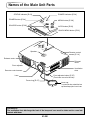
Names of the Main Unit Parts
STATUS indicator [E-61]
POWER indicator [E-24]
S
TA
TU
S
P
POWER button [E-24]
O
MENU button [E-38]
W
E
R
P
O
W
E
M
R
E
N
O
U
S
C
R
U
E
SOURCE button [E-28]
U
TO
QUICK MENU button [E-32]
DIO
EO
R
PO
SO
UR
C
AU
VID
Q
ME UIC
NU K
AU
A
K
IC
U U
Q EN
M
AUTO button [E-28]
TO
E
NU
WE
ME
ST
AT
US
PO
WE
R
Speaker
Remote control
sensor [E-14]
Exhaust vents
Exhaust
vents
Front adjuster
Ventilation
slots
Remote control sensor
Front adjuster button [E-27]
(There is also one on the left side.)
Lens
Focus ring [E-27]
Lens cap
To protect the lens, attach the lens
cap when the projector is not in use.
Precautions
The ventilation slots discharge the heat of the lamp and care must be taken not to come into
contact with them.
E-10
Names of the Main Unit Parts
AUDIO jack [E-23]
VIDEO jack [E-21, 22]
E
C
R
U
O
S
A
U
TO
K
IC
U U
Q EN
M
AU
DIO
PC connector [E-18,19,22]
VID
EO
PC
Ventilation slots
S
TU
TA
S
W
O
P
Built-in security slot
(See description below.)
R
E
M
R
E
W
O
P
N
E
U
E
C
R
U
O
S
U
A
TO
K
IC
U U
Q EN
M
AU
DIO
VID
E
O
PC
AC IN connector [E-24]
Rear adjuster [E-27]
Ventilation slots
Lamp cover [E-67]
Front adjusters [E-27]
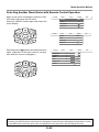
Built-in Security Slot
This security slot supports the MicroSaver Security System manufactured by
Kensington Microware Inc.
E-11
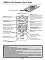
Names of the Remote Control Parts
N
VKST
EL
NC
CA
OM
ER
N
ST
HK
ZO
EN
T
AU
ME
NU
AS
QU
IC
PE
K
YC
S
VID
E
-VID
E
ITA
r
YP
MU
T
EZ
bP
OF
E
PO
E
r
PIP
RG
B
L
FR
E
bC
O
O
DIG
TO
CT
WE
F
R
Infrared transmitter [E-14]
ON
POWER button [E-24]
FREEZE button [E-31]
(Freezes moving pictures)
MUTE button [E-31]
(Temporarily cancels the
video and audio)
ON
POWER
OFF
FREEZE
MUTE
PIP
DIGITAL
RGB
YPbPr
VIDEO
S-VIDEO
YCbCr
QUICK
ASPECT
AUTO
QUICK button [E-32]
(Displays a simplified menu)
CAN
U
ASPECT button [E-30]
(Selects the vertical and horizontal ratio of the screen)
CEL
MEN
ENTER
HKS
HKSTN button [E-34]
(Horizontal keystone distortion
correction display)
N
TN
VKST
ZOOM
VOL
PIP button [E-31]
(Displays the picture associated
with the VIDEO connector as a
smaller picture within the display
screen associated with the PC
connector)
Buttons used for input selection [E-28]
DIGITAL button, RGB button,
YPbPr button, VIDEO button, SVIDEO button, and YCbCr button
AUTO button [E-29]
(Automatic adjustment of the
analog RGB moving image)
Buttons used for menu operations [E-37]
VKSTN button [E-34]
(Vertical keystone distortion correction display)
ZOOM button [E-35]
(Digital zoom adjustment display)
VOL button [E-36]
(Volume adjustment display)
+/– button
(Used in all adjustments)
Precautions
Handling of the Remote Control
* Do not drop the remote control or handle it inappropriately.
* Do not expose the remote control to water or other liquids. Should the remote control become
wet, wipe it dry immediately.
* Try to avoid use in hot and/or humid locations.
* Please keep button batteries out of the reach of children. If a battery is swallowed, promptly
obtain the medical care of a doctor.
* Remove the batteries from the remote control when it is not going to be used for a long period.
* Some operations (such as menu operations) are available only through the use of the remote
control and attention should be given to its careful handling.
E-12
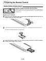
Preparing the Remote Control
Button Battery Replacement
Using the remote control for the first time
The battery compartment is fitted with a transportation insulation sheet at
the time of shipping. Pull out the sheet and remove it. The remote control is
now ready for use.
Replacement Method
the tip of a ballpoint pen or some other pointed object into the hole of the
1 Insert
battery holder, then pull out to open.
2
Remove the old battery and install a new button battery with (+) side facing upward in the battery holder.
25
20
LT
R
O
2- L iC E L L 3 V
C
M nO
S JAPAN H
Purchase a CR2025 type battery for replacement.
CR
202
5
25
20
LT
R
O
M nO
2- L iC E L L 3 V
CR
202
5
E-13
S JAPAN H
Insert the battery holder into the remote control and push in until the battery
holder closes with a "click" sound.
C
3
Preparing the Remote Control
Remote Control Range
Point the infrared transmitter of the remote control toward the remote control sensor located at the front
or rear of the main unit and operate.
Reception of the remote control signal should generally be possible within the range illustrated below.
4m
Remote control infrared
transmitter
/ 13
Remote control sensor
eet
.1 f
30˚
30˚
Side View
7m / 23 feet
4m
3.1
/1
t
fee
50˚
50˚
7m / 23 feet
Remote control
sensor
Top View
Remote control infrared
transmitter
Note
* Exposure of the main unit's remote control sensor or the remote control infrared transmitter to bright light or
the obstruction of the signal by an obstacle located in the pathway may prevent operation.
* The remote control will not function when the battery is exhausted.
E-14
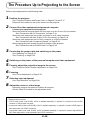
The Procedure Up to Projecting to the Screen
Perform setup adjustments in the following order.
1 Position the projector
See "Projection Distance and Screen Size" on Pages E-16 and E-17.
Determine the locations to set up the screen and the projector.
2 Connect the video equipment and personal computer
Connect your equipment to the projector.
When the personal computer has a DVI connector or a mini D-sub 15-pin connector
See "Connections with PC Connectors" on Page E-18.
When the video equipment has a video connector or an S-video connector
See "Connections with Mini D-Sub 15-Pin Connectors" on Page E-19.
When the video equipment has a YCbCr connector or a YPbPr connector
See "Connections with Component Signals" on Page E-22.
When playing the audio through the built-in speaker of the projector
See "Connections with the AUDIO Jack" on Page E-23.
3 Connecting the power cable and switching on the power
See "Operating" on Page E-24.
See "Finishing" on Page E-25.
4 Switching on the power of the personal computer and video equipment
5 Properly adjust the projection image to the screen
See "Projection Screen Position Adjustment" on Page E-26.
6 Focusing
See "Focus Adjustment" on Page E-27.
7 Selecting input equipment
See "Input Selection" on Page E-28.
8 Adjust the screen or video image
Adjust the image to the optimum condition as required.
See the Table of Contents for the adjustment items.
Note
* Please purchase a screen.
* A DVI-D cable (order code 28-697), which is available separately, is required for connections with the DVI
connector of the personal computer.
* A component cable (order code 28-698), which is available separately, is required to connect a DVD player or
other equipment with YCbCr connectors.
* A component cable (order code 28-690), which is available separately, is required to connect high definition
(HD) video equipment or other equipment with YPbPr connectors.
E-15
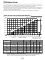
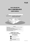
Placement Guide
● Use this information as a guide to find out about the screen size when the projector is placed at a
certain location, or to find out the approximate size of a screen that will be required.
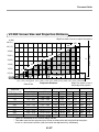
● The projection distance over which focussing is adjustable is 1.2 m (3.9 feet) to 6.9 m (22.6 feet) from
the front of the main unit lens for V-807 and 1.2 m (3.9 feet) to 6.6 m (21.7 feet) for V-1080. The
projector should be placed within this range.
● Please see the projection distance table for the model of projector that you have purchased.
V-807 Screen Size and Projection Distance
m (feet)
4.0(13.1)
Height from center of lens to top edge of the projection
200"
180"
3.5(11.5)
2.5(8.1)
120"
100"
2.0(6.6)
h1
80"
1.5(4.9)
60"
Screen Height
150"
3.0(9.8)
40"
1.0(3.3)
35"
0.5(1.6)
h2
17.2˚ Projection angle
0
0.5 1.0 1.5 2.0 2.5 3.0 3.5 4.0 4.5 5.0 5.5 6.0 6.5 7.0 (m)
(1.6) (3.3) (4.9) (6.6) (8.1) (9.8) (11.5) (13.1) (14.8) (16.4) (18.0) (19.7) (21.3) (23.0) (feet)
Projection Distance
Height from center of lens to
Center of lens
bottom edge of the projection
Screen Size
Designation (Inches)
35"
40"
60"
80"
100"
120"
150"
180"
200"
Screen Size Width x Height
(m)
(feet)
0.710.53
0.810.61
1.220.91
1.631.22
2.021.52
2.441.83
3.052.29
3.662.74
4.063.05
2.331.74
2.662.00
4.002.99
5.354.00
6.634.99
8.006.00
10.007.51
12.008.99
13.3210.00
Projection Distance
(m)
(feet)
1.20
1.37
2.06
2.75
3.43
4.12
5.15
6.18
6.87
3.94
4.49
6.76
9.02
11.25
13.52
16.90
20.28
22.54
Height h1
(m)
(feet)
2.10
0.64
2.40
0.73
3.58
1.09
4.79
1.46
5.97
1.82
7.19
2.19
8.99
2.74
3.29 10.79
3.65 11.98
Height h2
(m)
(feet)
0.36
0.11
0.39
0.12
0.59
0.18
0.79
0.24
0.98
0.30
1.18
0.36
1.48
0.45
1.77
0.54
1.97
0.60
* There is a tolerance of ±5% due to design values.
* This table uses the lens apex and lens center as references and requires that the projector be in a horizontal condition (with front and rear adjusters fully withdrawn).
E-16
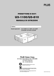
Placement Guide
V-1080 Screen Size and Projection Distance
Height from center of lens to top edge of the projection
m (feet)
4.0(13.1)
200"
180"
3.5(11.5)
2.5(8.1)
120"
100"
2.0(6.6)
h1
80"
1.5(4.9)
60"
Screen Height
150"
3.0(9.8)
40"
1.0(3.3)
36"
0.5(1.6)
h2
17.2˚ Projection angle
0
0.5 1.0 1.5 2.0 2.5 3.0 3.5 4.0 4.5 5.0 5.5 6.0 6.5 7.0 (m)
(1.6) (3.3) (4.9) (6.6) (8.1) (9.8) (11.5) (13.1) (14.8) (16.4) (18.0) (19.7) (21.3) (23.0) (feet)
Projection Distance
Height from center of lens to
Center of lens
bottom edge of the projection
Screen Size
Designation (Inches)
36"
40"
60"
80"
100"
120"
150"
180"
200"
Screen Size Width x Height
(m)
(feet)
0.740.55
0.810.61
1.220.91
1.631.22
2.021.52
2.441.83
3.052.29
3.662.74
4.063.05
2.431.80
2.662.00
4.002.99
5.354.00
6.634.99
8.006.00
10.007.51
12.008.99
13.3210.00
Projection Distance
(m)
(feet)
1.20
1.32
1.99
2.65
3.31
3.97
4.97
5.96
6.62
3.94
4.33
6.53
8.69
10.86
13.02
16.31
19.55
21.72
Height h1
(m)
(feet)
2.13
0.65
2.36
0.72
3.51
1.07
4.69
1.43
5.87
1.79
7.02
2.14
8.79
2.68
3.21 10.53
3.57 11.71
Height h2
(m)
(feet)
0.33
0.10
0.36
0.11
0.52
0.16
0.69
0.21
0.85
0.26
1.02
0.31
1.28
0.39
1.54
0.47
1.71
0.52
* There is a tolerance of ±5% due to design values.
* This table uses the lens apex and lens center as references and requires that the projector be in a horizontal condition (with front and rear adjusters fully withdrawn).
E-17
Connecting Personal Computers and Video Equipment
● Connecting this unit with a personal computer permits presentation data to be projected as a large
screen display at conferences, lectures, and on other occasions. Furthermore, connecting this unit to
a DVD player or other video equipment source in combination with an audio/video amplifier and speaker
system will allow you to enjoy convincing home theater.
Connections with PC Connectors
Please check the following matters before making connections to the
personal computer.
* Suitable resolution for V-807 is 800 x 600 dots (S-VGA), and the displayable resolution is XGA (1024 x
768 dots).
* Suitable resolution for V-1080 is 1024 x 768 dots (XGA), and the displayable resolution is S-XGA (1280
x 1024 dots).
Note that input of a resolution that exceeds the displayable resolution will cease to be projected and
should this be the case, you will need to change the resolution to a displayable resolution at the
computer side. Check with "Table of Supported Frequencies" on Page E-70.
* The setting method of the personal computer will differ depending on the personal computer that you
are using. For information, read the instruction manual for your personal computer, read the on-line
help, or contact the manufacturer of your personal computer.
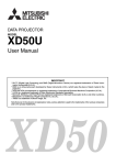
Personal Computers with a DVI Connector
* Make the connection with a DVI-D cable and the PC connector of the projector.
When connecting, arrange the connectors in the proper orientation and plug in. Turn the screw knobs
and fasten to the connector of the main unit.
* Switch the input selection of the projector to "Digital RGB".
Monitor output
AUDIO VIDEO
PC
Personal
computer
DVI-D cable (Available as an option. Order code: 28-697)
Note
This projector uses a 29-pin DVI connector that supports the digital interface. Digital signal TMDS (Transition
Minimized Differential Signalling) of the DVI (Digital Visual Interface) standard is used.
E-18
Connecting Personal Computers and Video Equipment
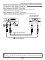
Personal Computers with a Mini D-Sub 15-Pin Connector
* Make the connection to the projector's PC connector and the mini D-sub 15-pin connector through the
use of a DVI/mini D-sub 15-pin conversion cable.
* When connecting, arrange the connectors in the proper orientation and plug in. Turn the screw knobs
and fasten to the connector of the main unit.
* Switch the input selection of the projector to "Analog RGB".
Personal computer
AUDIO VIDEO
PC
DVI/mini D-sub 15-pin conversion
cable (Supplied item)
Monitor output
RGB signal cable (Supplied item)
Note
* Before making connections, check the power of the projector and the equipment to be connected is switched
off.
* When projection will be with a notebook computer connected, knowledge will be required for the cable connection and notebook computer startup procedure as well as the operation that follows startup. Please consult the
instruction manual of your notebook computer or the on-line help.
E-19
Connecting Personal Computers and Video Equipment
To Output the External Output Signal of a Notebook Computer
When projection will be with a notebook computer connected, knowledge will be required for the cable
connection and notebook computer startup procedure as well as the operation that follows notebook
startup. Please consult the instruction manual of your notebook computer or the on-line help while performing the following procedure.
whether a signal is being sent from the notebook computer to the projector.
1 Check
An indication appearing on the liquid crystal display of the notebook computer does not necessarily
mean that an external output signal is being output.
a sign not be output from the notebook computer, please try the operation described below.
2 Should
For an IBM PC/AT, DOS/V computer, press the [Fn] key plus any one of the [F1] to [F12] keys. (See
the table below.)
Manufacturer
akia
COMPAQ
DELL
FUJITSU
GATEWAY
IBM
NEC
Panasonic
SHARP
SONY
SOTEC
TOSHIBA
Model
All computers
ARMADA Series
PRESARIO Series
All computers
All computers
All computers
All computers
All computers
All computers
All computers
All computers
All computers
All computers
Key
Fn + F2
Fn + F4
Fn + F3
Fn + F8
Fn + F10
Fn + F3
Fn + F7
Fn + F3
Fn + F3
Fn + F5
Fn + F7
Fn + F3
Fn + F5
Note: Table information is current to June 2001.
Note
When the liquid crystal display of the notebook computer and the projector are displayed at the same time, the
projected image might not be correct even though the liquid crystal display shows a correct indication. Should
this occur, stop the simultaneous display of the notebook computer and try the mode with external output only.
(Try an operation such as that described in aforementioned Step 2 and try closing the liquid crystal panel which
might result in external output only.)
E-20
Connecting Personal Computers and Video Equipment
Connections with Video Connectors
Video Equipment with VIDEO Connectors
* Make the connection to the VIDEO connector of the projector using a video cable.
* Switch the input selection of the projector to "Video".
Video Equipment with S-VIDEO Connectors
* Make the connection to the VIDEO connector of the projector using an S-video cable.
* Switch the input selection of the projector to "S-Video".
Video deck, DVD player,
document camera, etc.
AUDIO VIDEO
PC
S-VIDEO
VIDEO
S-Video cable (Suppled item)
Video cable (Supplied item)
Note
This projector's video cable and S-video cable are special cables. When purchasing extension cables, please
contact your dealer.
E-21
Connecting Personal Computers and Video Equipment
Connections with Component Signals
When the Video Connectors are Y, Cb, and Cr Connectors
* Make the connection to the projector's VIDEO connector using a component signal cable.
* Switch the input selection of the projector to "YCbCr".
When the Video Connectors are Y, Pb, and Pr Connectors
* Connect a DVI/mini D-sub 15-pin conversion cable to the PC connector of the projector, then make a
further connection using a component cable (which is available as an option).
* Switch the input selection of the projector to "YPbPr".
Component cable (Available as an option)
(3.5 mm diameter, 4 Pde, Plug to RCA3)
(Order code: 28-698)
Green
Blue
Red
AUDIO VIDEO
PC
Y
Cb
Cr
COMPONENT
DVD player, HD video
deck, etc.
DVI/mini D-sub 15-pin conversion
cable (Supplied item)
Y
COMPONENT
Pb
Pr
Blue
Green
Component cable (Available as an option)
(D-sub 15-pin to RCA3)
(Order code: 28-690)
Note
YCbCr cannot accept the input of signals other than NTSC 3.58 and PAL.
E-22
Red
Connecting Personal Computers and Video Equipment
Connections with Audio Connectors
* Make the connection to the projector's AUDIO jack using an audio cable.
* The built-in speaker of the projector provides monaural audio.
* To enjoy convincing audio reproduction, please connect the audio output of the video equipment to
your audio system.
Video equipment, personal computer
AUDIO VIDEO
PC
AUDIO
L
R
White
Red
Audio cable (Supplied item)
Note
The AUDIO jack of the projector is a 2.5 mm diameter stereo mini jack. Connection is not possible using the
common (3.5 mm diameter) stereo mini jack cable from the headphone jack of the personal computer or video
equipment.
E-23
Power Cable Connections and Switching the Power On/Off
There is an order in which the power cable is connected and the power is switched on/off.
Operating
1 Connect the AC IN connector of the projector and the power outlet using the supplied power cable.
The POWER indicator will light amber, the cooling fan will rotate at low speed, and the unit will enter
the standby mode.
STATUS POWER
Lit amber
S
TA
TU
S
P
O
W
E
R
To wall outlet
P
O
W
E
M
R
E
N
E
C
R
U
O
U
S
A
U
TO
K
IC
U U
Q EN
M
Firmly plug in all the way.
AU
DIO
VID
EO
PC
2 Switch on the projector power
Main unit operation: Press and hold the POWER button for a while.
Remote control operation: Press the POWER ON button.
ON
POWER
OFF
STATUS POWER
POWER
STATUS POWER
STATUS POWER
Lit green
Flashes green
(Approximately 60 Power is on
seconds)
The POWER indicator changes to a flashing green and lights steadily after about 60 seconds.
The projection screen brightens after about 40 seconds.
The projector is now capable of regular projection.
3 Switch on the power of the connected equipment
Note
When the power plug will be unplugged from the power outlet, please place the projector near the power outlet so
that it may be reached easily.
E-24
Power Cable Connections and Switching the Power On/Off
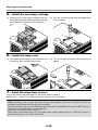
Finishing
1 Switch off the power of the connected equipment
2 Switch off the power of the projector
Main unit operation: Press and hold the POWER button for a while.
Remote control operation: Press the POWER OFF button.
ON
POWER
OFF
The "Power Off" indication will appear.
When the red bar extends fully (in about 5 seconds), the projection screen will go off and the
unit will enter the power off operation.
Power Off
OK ?
Note
* The operation can be cancelled by pressing a button other than the POWER button.
* One more press of the POWER (POWER OFF)
button will switch off the power.
The POWER indicator changes to flashing amber and lights a steady amber after about 60 seconds (when the unit enters the standby mode).
Power Off
OK ?
STATUS POWER
POWER
3 Unplug the power cable
STATUS POWER
Flashes amber
(Approximately 60
seconds)
STATUS POWER
Lit amber
Standby
mode
Check that the POWER indicator is lit in amber and then unplug the power cable.
The POWER indicator will go off when the power cable is unplugged.
Warrning
Under normal circumstances, please do not unplug the power cable unless the POWER indicator
is lit in amber. Doing so may shorten the life of the lamp or result in breakdown of the projector.
Do not unplug the power cable while the POWER indicator is flashing amber. Doing so may
shorten the life of the lamp or damage the projector.
E-25
Adjustment of the Projection Screen
Switch on the power of the connected equipment and make the adjustments with the video signal
being input to the projector.
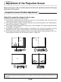
Projection Screen Position Adjustment
Adjust the projection image to the screen.
Check that the screen is set level and vertically.
(1) If the image is shifted to the left or right, move the main unit horizontally. (Align the center of the
screen and the center of the lens of the main unit.)
(2) If the image is shifted vertically, move the image up or down with the adjuster. See "Making Adjustments with the Adjusters" on Page E-27.
(3) If the image is slanted, adjust by turning the right or left front adjuster. See "Making Adjustments with
the Adjusters" on Page E-27.
(4) A projection image such as that illustrated in the diagram is the result of the projector not being
perpendicular to the screen. Set the projector so that it is pointing straight toward the screen.
(5) If the image shows keystone distortion, adjust using remote control or menu operations. See "Correcting Keystone Distortion of the Projection Image" on Page E-34.
(3)
(1)
(2)
(4)
(5)
Note
The projection image can be turned upside down or turned left to right using menu operations. See "Projection" on
Page E-52.
E-26
Adjustment of the Projection Screen
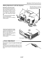
Making Adjustments with the Adjusters
Care must be taken not to come into
contact with the ventilation slots which
discharge the heat of the lamp.
Q
ME UIC
NU K
SO
PO
WE
R
UR
AU
TO
CE
ME
NU
STA
TU
S
PO
WE
R
Raising the projection image
While viewing the projection image, press hand hold the front adjuster buttons located at the left
and right (1) and, raise the projector to align the image with the
screen, then release your fingers
(2).
Turn the left and right front adjusters for fine adjustment.
Adjust so that there is no shaking
of the projector.
(1)
(2)
(1)
S
Lowering the projection image
Lower the front adjusters using the
operation described above.
Raise the rear adjuster. Turn the
left and right front adjusters to
make fine adjustments.
Adjust so that there is no shaking
of the projector.
TA
TU
S
P
O
W
E
R
E
C
R
U
O
S
U
N
E
M
R
E
W
O
P
VID
EO
PC
Rear adjuster
Focus Adjustment
Turn the focus ring to the right or left and adjust
the focus.
Should the size of the projection image extend beyond the screen or be smaller than the screen, move
the projector forward or backward and readjust the
focus.
E-27
TO
U
A
K
IC
U U
Q EN
M
AU
DIO
General Operation
This section describes the use of direct operation with the main unit or remote control buttons.
For information about operation using the menu, see "Menu Operation Method" on Page E-37 and
the various items on Pages E-46 to E-60.
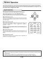
Input Selection
This operation selects the input signal to be projected.
MENU
Main unit operation: Press the SOURCE button.
(It will not function while the menu or the quick menu is displayed.)
When Auto Source is On
If there is no input signal at the source that was previously used,
the projector automatically selects another source that has the
next input signal.
When Auto Source is Off
Each press of the button switches the selection one step in the
sequence of Analog RGB → YPbPr → Digital RGB → VIDEO →
S-VIDEO → YCbCr.
Remote control operation: Press the desired input selection button.
When Auto Source is On
When an input signal is not present at the selected source, the
projector automatically selects the next source that has an input
signal.
AUTO
SOURCE
QUICK
MENU
ON
POWER
OFF
FREEZE
MUTE
PIP
DIGITAL
RGB
YPbPr
VIDEO
S-VIDEO
YCbCr
QUICK
ASPECT
AUTO
When Auto Source is Off
The projector switches to the selected source regardless of
whether an input signal is present.
Note
* When you do not operate source selection, the projector will assume the input selection condition that was
previously used.
* See "Auto Source" on Page E-55 for information about the Auto Source on and off conditions.
* YPbPr input selection will not be possible when YPbPr is set invalidly. See "YPbPr" on Page E-57.
E-28
General Operation
Automatic Adjustment of Analog RGB
This function automatically adjusts the position shift of the analog
RGB input signal, the size of the picture, vertical striping, and
color infidelity.
Normally, this function is adjusted automatically at the time of signal selection.
MENU
AUTO
SOURCE
Main unit operation/Remote control operation: Press the
AUTO button. (This will not function while the menu or the quick
menu is displayed.)
A press of the AUTO button starts the automatic adjustment.
QUICK
MENU
ON
POWER
OFF
FREEZE
MUTE
PIP
DIGITAL
RGB
YPbPr
VIDEO
S-VIDEO
YCbCr
QUICK
ASPECT
AUTO
Note
* If the display position is shifted, vertical lines appear on the picture, or the projection is not good even after
using automatic adjustment, please perform image adjustment manually. See "Picture Adj. / Fine Picture / H
Position / V Position " on Page E-47.
* When the image extends beyond the boundaries of the screen or is smaller than the screen, set Aspect to
"Auto". See "Selection of Aspect Ratio" on Page E-30 and "Aspect" on Page E-51.
E-29
General Operation
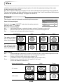
Selection of Aspect Ratio
This function selects horizontal and vertical picture proportions of the input signal.
Press the ASPECT button while viewing the projected image
and select the aspect ratio.
Personal Computer Image
(when selecting digital RGB or analog RGB)
Each press of the ASPECT button advances the selection one
step in the sequence of Auto → Direct → Real, and then repeats.
Auto ............ Automatically enlarges or reduces the image to project a
full screen in a ratio of 4:3
Direct .......... Maintains the aspect ratio and projects a picture of the maximum displayable size
Real ............ Projects the input signal without pixel conversion
DIGITAL
RGB
YPbPr
VIDEO
S-VIDEO
YCbCr
QUICK
ASPECT
AUTO
U
MEN
CAN
CEL
Image of the Video Equipment
(when selecting VIDEO, S-VIDEO, YCbCr, or YPbPr)
Each press of the ASPECT button advances the selection one
step in the sequence of Auto → Wide → Zoom, and then repeats.
Auto ............ While maintaining the aspect ratio, projects a full screen so
that no portions extend beyond the boundaries of the screen.
The top and bottom of the 16:9 image becomes black.
Wide ........... Projects to fill the full width with the entire image at 16:9.
Zoom .......... Projects only the 4:3 portion within 16:9 image to fill the
screen.
Note
Please note that using this monitor for the purpose of commercial gain or the attraction of public attention in a
venue such as a coffee shop or hotel and projecting a 4:3 screen in wide mode or leaving a squeezed screen as a
compressed image raises concern about the infringement of copyright rights which are protected by copyright
law.
E-30
General Operation
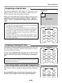
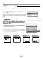
Projecting a Sub-Picture
This function displays the video image (i.e., the picture of the
VIDEO connector input) on the personal computer screen (i.e.,
the PC connector input screen) as a sub-picture.
Sub-picture
Each press of the PIP button advances the screen size of the
sub-picture one step in the sequence of Small → Medium →
Large → Off (i.e., the sub-picture display is off), and then repeats.
Note
* The sub-picture cannot be displayed when the main screen receives
the image from the VIDEO connector.
* The sub-picture cannot be displayed when picture in picture is set
to off. The size of the sub-picture can be selected. See "Using the
Quick Menu" on Page 32 and "Picture in Picture" on Page E-54.
* To change the display position of the sub-picture, see "Picture in
Picture" on Page E-54.
* The main picture is termed the Analog RGB, Digital RGB, or YPbPr
input screen, whereas the sub-picture is termed the VIDEO, S-VIDEO,
and YCbCr input screen.
Main-picture
ON
POWER
OFF
FREEZE
MUTE
PIP
DIGITAL
RGB
YPbPr
VIDEO
S-VIDEO
YCbCr
QUICK
ASPECT
AUTO
ON
POWER
OFF
FREEZE
MUTE
PIP
DIGITAL
RGB
YPbPr
VIDEO
S-VIDEO
YCbCr
QUICK
ASPECT
AUTO
ON
POWER
OFF
FREEZE
MUTE
PIP
DIGITAL
RGB
YPbPr
VIDEO
S-VIDEO
YCbCr
Freezing a Moving Picture
This function is used to stop and view a moving picture. Note that
the input image continues to advance even though the picture
there is a still picture condition.
A press of the FREEZE button changes the screen to a still
picture. A further press returns the screen to a moving picture.
Note
During a picture in picture display, both the main picture and the subpicture become still pictures.
Cancelling Video and Audio Temporarily
This function is used to cancel the video and audio at the same
time.
Press the MUTE button to cancel the video and the audio.
A further press brings a return to the original condition.
E-31
General Operation
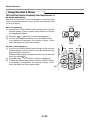
Using the Quick Menu
This function permits frequently used adjustments to
be performed quickly.
Note that the Quick Menu will not be displayed unless the signal
of the connected equipment is input. Please select the input that
you wish to adjust.
MENU
Main unit operation
(1) A press of the QUICK MENU button brings up the quick adjustment display. Further presses allow selection of the desired adjustment display.
(2) Press the
or
button to make the adjustment.
(3) To close the display immediately, press the MENU button.
In the absence of operations for a period of about 10 seconds, the display will close automatically.
Remote control operation
(1) A press of the QUICK MENU button brings up the quick adjustment display. Further presses cause the adjustment display to change in sequence.
The adjustment display can be selected with use of either the
cursor ▲ or ▼ button.
(2) Press the cursor or button to make the adjustment.
(3) To close the display immediately, press the CANCEL button.
In the absence of operations for a period of about 10 seconds, the display will close automatically.
(2)
E-32
AUTO
SOURCE
QUICK
MENU
(1)
(3)
QUICK
ASPECT
AUTO
CAN
U
CEL
MEN
ENTER
HKS
TN
N
VKST
General Operation
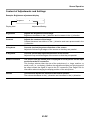
Content of Adjustments and Settings
Example: Brightness adjustment display
Brightness
Display Item
0
–
+
Adjustment/Setting
Brightness
Adjusts the brightness of the image.
Brightness decreases in the (-) direction and increases in the (+) direction.
Contrast
Adjusts the contrast of the image.
Contrast becomes less distinct in the (-) direction and more pronounced in the
(+) direction.
V Keystone
Corrects (vertical) keystone distortion of the screen.
Adjusts the left and right edges of the screen so that they are parallel.
H Keystone
Corrects (horizontal) keystone distortion of the screen.
Adjusts the up and down edges of the screen so that they are parallel.
Picture in Picture
The picture from the VIDEO jack is displayed as a sub-picture on the input
screen from the PC connector.
This function selects either the size of the sub-picture (i.e., large, medium, or
small) or off (i.e., no display). (Neither the adjustment display nor the picture will
be output unless the signal is input to the PC connector.) See Page E-54 for
information about changing the display position of the sub-picture.
Volume
This function adjusts the volume of the built-in speaker.
The volume decreases in the (-) direction and increases in the (+) direction.
E-33
General Operation
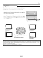
Correcting Keystone Distortion of the Projection Screen
This adjustment is used when the projection screen is distorted.
Note that extreme distortion cannot be corrected and in such circumstances the projector should be placed to face the screen
straight on beforehand.
(3)
CAN
U
CEL
MEN
ENTER
HKS
N
TN
VKST
ZOOM
VOL
(1)
(1)
(2)
Adjustment Method
(1) To adjust up-down distortion (e.g., Screen Example 1), press
the HKSTN button. The horizontal keystone adjustment display will appear.
V Keystone
0
–
+
Screen Example 1
To adjust left-right distortion (e.g., Screen Example 2), press
the VKSTN button. The vertical keystone adjustment display
will appear.
H Keystone
0
–
+
Screen Example 2
(2) While viewing the screen, press the (+) button or the (-) button and adjust the vertical or horizontal edges to be parallel.
In Screen Example 3, horizontal and vertical keystone distortion should be adjusted.
(3) To close the display immediately, press the CANCEL button.
In the absence of operations for a period of about 10 seconds, the display will close automatically.
Screen Example 3
Note
* The keystone adjustment values can be overwritten and saved. See "Keystone" on Page E-53.
* Overcompensation of the horizontal keystone correction value will result in a narrowing of the vertical keystone
adjustment range. Likewise, overcompensation of the vertical keystone correction value results in a narrowed
horizontal adjustment range.
* Note that the adjustment range will differ depending on the adjustment conditions.
* The screen examples have been depicted in an exaggerated form to aid in description.
E-34
General Operation
Enlargement of the Image and Video Movement
This function digitally enlarges the personal computer image and
video image (up to 10 times).
(3)
(1) Press the ZOOM button.
The zoom selection display will appear.
CAN
U
MEN
Zoom
21 –
(4)
CEL
+
ENTER
(2) Enlarge to the desired size.
Each press of the (+) button enlarges the image and each
press of the (-) button makes the image smaller (returning it
to 1:1).
(3) Pressing the cursor (▲▼ ) buttons at the time of the zoom
operation will cause the display position to move.
(There will not be any movement when zoom is at 0.)
HKS
N
TN
VKST
ZOOM
VOL
(2)
(1)
(4) To close the display immediately, press the CANCEL button.
In the absence of operations for a period of about 10 seconds, the display will close automatically.
(1)
(2)
(No enlargement)
(3)
(Approximately 2 times enlargement)
(Movement)
The image can also be moved in the following circumstances.
*
*
When "Aspect" is set to "Real" by the signal of the personal computer, and the input resolution is
higher than the display resolution of the projector.
When "Aspect" is set to "Zoom" by the video signal.
Note
* Zoom and image movement functions are cancelled when the input is switched.
* The greater the zoom enlargement, the less distinct the image will appear. The reason for this is that the dots are
being digitally corrected so that they are not conspicuous.
* Movement of the screen will not be possible when the menu screen is being displayed.
E-35
General Operation
Adjustment of the Volume
This function adjusts the volume of the built-in speaker.
(1) Press the VOL button.
The volume adjustment display will appear.
Volume
53
–
(3)
CAN
U
CEL
MEN
+
ENTER
(2) Adjust the volume.
The (+) button increases the volume and the (-) button decreases the volume.
(3) To close the display immediately, press the CANCEL button.
In the absence of operations for a period of about 10 seconds, the display will close automatically.
E-36
HKS
N
TN
VKST
ZOOM
VOL
(2)
(1)
Menu Operation Method
● This section describes only the menu operation method. Please see this page should you need information while performing menu operations.
● For information about a menu function, adjustment, or setting, please see one of the pages containing
such descriptions.
● Adjustments and settings are made by projecting an image and adjusting to an optimum condition.
● The remote control should be pointed toward the remote control sensor of the projector and operated.
● To return the various items that have been changed via the menu to their standard values (i.e., default
values at time of shipping from the factory), see "Factory Default" on Page E-59. (Some items will not
return to their initial values.)
● The adjustment/setting items and contents will differ depending on the input selection and the adjustment/setting items that can be used with the input signal are displayed on the menu.
Names and Functions of the Parts
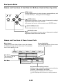
Names and Functions of the Remote Control Buttons that Operate Via a
Menu
ON
POWER
OFF
FREEZE
MUTE
PIP
DIGITAL
RGB
YPbPr
VIDEO
S-VIDEO
YCbCr
QUICK
ASPECT
AUTO
Cursor (▲▼ ) buttons
Used in the selection of menu names and item names as
well as in setting and adjusting the item contents.
CANCEL button
Used to return to menu name selection as well as to close
the menu (and the sub menu display).
CAN
U
CEL
MEN
ENTER
HKS
MENU button
Used for menu display and menu closure.
ENTER button
Used to set the verification display.
N
TN
VKST
ZOOM
VOL
E-37
Menu Operation Method
Names and Functions of the Main Unit Buttons Used in Menu Operation
STATUS POWER
POWER
MENU button
Used to display menus, to return to menu name selections, and
to close menus (i.e., closing sub menu displays).
MENU
SOURCE
(AUTO) button
Advances the selection of menu names. Advances the setting/
adjustment values of the item contents.
Also serves the function of the remote control ENTER button.
AUTO
QUICK
MENU
(QUICK MENU) button
Used in the selection of item names.
(SOURCE) button
Returns to the selection of menu names. Advances the setting/
adjustment values of the item contents.
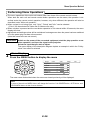
Names and Functions of Menu Screen Parts
Menu Names
These are the menu titles. When a menu is selected,
the display changes to the title screen. The selected
menu name appears in red.
Image
Color
View
Setup
Aspect
Item Name
The name of the adjustment/setting
Sub Menu
Cursor (dark blue)
The setting/adjustment of the cursor
position can be performed.
Info.
Auto
Filter
3
Projection
Keystone
V Keystone
0
H Keystone
0
+
+
–
–
Off
Keystone Save
Adjustment bar setting contents
Adjustment bar: Indicates the adjustment condition by
increases or decreases in bar length
Setting contents: Displays the set contents
Icon: Displays the sub menu or setting contents
E-38
Menu Operation Method
Performing Menu Operations
● The menu operations of the main unit buttons differ from those of the remote control buttons.
When both the main unit and remote control button operations are the same, the operation is described under the remote control operation; however, only when different, the operation will also be
described under "Main unit operation".
● When a signal is not being input, only “Color”, "Setup" and "Info." can be selected.
("Color" can be selected for Video and S-Video source only.)
● When a button is pressed and the next button operation is not entered within 30 seconds, the menu
display will close.
● Adjustment and settings values will be maintained in storage even when the power has been switched
off or the power plug has been disconnected.
(Note that some items are not stored.)
Preparation
1
Switch on the power of the connected equipment, start the play operation or another operation, and input the signal to the projector.
Select the input that you wish to adjust.
The menu display of the description diagram depicts an example in which the "H Keystone" item name is selected.
Menu Display
Press the MENU button to display the menu
CAN
U
CEL
MEN
ENTER
HKS
TN
N
VKST
Image
Color
View
Setup
Brightness
0
–
+
Contrast
0
–
+
Color
0
–
+
Tint
0
–
+
Sharpness
0
–
+
Info.
Reset
The menu name that existed when the menu was closed previously will be displayed.
Note
A press of the main unit MENU button will change the function of the SOURCE button, AUTO button, and
QUICK MENU button to that of cursor buttons.
E-39
Menu Operation Method
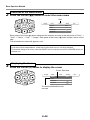
2
Selection of the Menu Name
Press the cursor (
)
button to select the menu name
Red
CAN
U
CEL
MEN
Image
ENTER
Color
View
Aspect
Filter
HKS
Info.
3
Projection
N
VKST
TN
Setup
Auto
Keystone
Each press of the cursor () button advances the selection one step in the sequence of "Color" →
"View" → "Setup" → "Info." → "Image". Each press of the cursor () button causes a return of one
step.
The selected menu name will appear in red.
Note
At the time of menu name selection, check that the item name cursor is not being displayed.
To cancel the display of the cursor, press the CANCEL button on the remote control or the MENU button on
the main unit.
3
Displaying the Cursor
Press the cursor (▼) button to display the cursor
Cursor: Dark blue
CAN
U
CEL
MEN
Image
ENTER
Color
View
Aspect
Filter
HKS
TN
Projection
N
VKST
Keystone
This condition allows selection of the
item name.
E-40
Setup
Auto
3
Info.
Menu Operation Method
4
Selection of the Item Name
Press the cursor (▲▼) button to align the cursor with the item name
CAN
U
CEL
MEN
Image
ENTER
Color
View
Aspect
Filter
HKS
Info.
3
Projection
N
VKST
TN
Setup
Auto
Keystone
Main unit operation: Press the (QUICK MENU) button. When the cursor has moved to the very
bottom of the items, another press will move it to the very top of the items.
Press the cursor () button since the "Keystone" example of the description diagram
displays the
icon. The sub menu will be
displayed.
Press the cursor (▼) button and align the cursor with the desired item name.
When the
icon is displayed and depending on the item contents, a press of the cursor () button will result in the setting display,
a resetting of the adjustment value, or a resetting verification display. Please see the various item descriptions.
5
Image
Color
View
Aspect
Setup
Info.
Auto
Filter
3
Projection
Keystone
V Keystone
0
–
H Keystone
0
–
+
+
Off
Keystone Save
Making Adjustments/Settings
Press the cursor ( ) button and make the adjustment (or setting)
while viewing the image
When a button is pressed, the image will also change.
Image
CAN
U
CEL
MEN
Color
View
Aspect
Filter
ENTER
HKS
TN
Setup
Info.
Auto
3
Projection
N
VKST
Keystone
V Keystone
0
–
H Keystone
0
–
Keystone Save
+
+
Off
Adjustment display: Each press of the button results in a change of 1 point and continued presses
cause changes to proceed in order.
Setting display: The setting contents display changes with each press of the button.
E-41
Menu Operation Method
6
Closing the Menu
Press the MENU button and close the menu display
CAN
U
CEL
MEN
ENTER
HKS
N
VKST
TN
Main unit operation: Press the MENU button and cancel the cursor display.
When a sub menu is displayed, press the MENU button to close the sub menu, then press again to
cancel the cursor. This condition allows the menu name to be selected.
MENU
Image
Cursor
Color
View
Aspect
Filter
SOURCE
Setup
Info.
Auto
3
Projection
AUTO
Keystone
QUICK
MENU
Image
A press of the MENU button while the
cursor is not displayed will close the menu
display.
Color
Aspect
Filter
Projection
Keystone
E-42
View
Setup
Auto
3
Info.
Menu Operation Method
Selecting Another Menu Name with Remote Control Operation
When a sub menu is displayed, press the CANCEL button and close the sub menu.
Press the CANCEL button again and cancel the
cursor display.
Image
Color
View
Setup
Info.
Auto
Aspect
3
Filter
Projection
Keystone
CAN
U
CEL
MEN
Image
Color
View
Setup
Info.
ENTER
Aspect
Auto
Filter
HKS
N
3
Projection
VKST
TN
Keystone
Press the cursor ( ) button and select the menu
name. (Selection of the menu name is not possible while the cursor is displayed.)
CAN
U
Color
View
Setup
0
–
+
Contrast
0
–
+
Color
0
–
+
Tint
0
–
+
Sharpness
0
–
+
Info.
Reset
CEL
MEN
Image
Brightness
ENTER
HKS
TN
N
VKST
Note
A press of the QUICK button while the menu is displayed will close the menu and display the quick menu. A press
of the MENU button while the quick menu is displayed will close the quick menu and display the menu.
E-43
Menu Operation Method
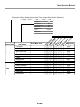
List of Item Names Offering Input Selection and Adjustments/Settings
The item names that can be adjusted/set will differ depending on the input signal.
[Example of Menu Display Items at the Time of Input Signal Video Selection]
Image
Color
View
Aspect
Setup
Info.
Auto
Filter
3
Projection
Keystone
V Keystone
0
–
H Keystone
0
–
+
+
Off
Keystone Save
Image
Color
View
Brightness
Contrast
Picture Adj.
Fine Picture
H Position
V Position
Color
Tint
Sharpness
Reset
Gamma
Color Temp.
Color System
Color Space
Aspect
Filter
Projection
Keystone
Picture in Picture
Vertical Flip
Horizontal Flip
V Keystone
H Keystone
Keystone Save
Size
Position
ita
og
ig
al
Sub Menu Item
Name
D
Item Name
An
Menu Name
R
G
B
l
YP R
G
bP B
YC r
bC
Vi r
de
o
SVi
de
o
Input Signal
"Tint" can be adjusted only at the time of NTSC composite/S signal input.
E-44
Reference
Page
E-46
E-46
E-47
E-47
E-47
E-47
E-46
E-46
E-46
E-48
E-49
E-49
E-50
E-50
E-51
E-52
E-52
E-52
E-53
E-53
E-54
E-54
E-54
Menu Operation Method
[Example of Menu Display Items at the Time of Input Signal Video Selection]
Image
Color
View
Setup
Info.
Language
Auto Source
On
Auto Power Off
Off
On Screen
On
Menu Position
YPbPr
Disable
Background
Black
Menu Name
Setup
Info.
Item Name
Sub Menu Item
Name
An
al
o
D gR
ig
ita GB
YP l R
bP GB
YC r
bC
Vi r
de
o
SVi
de
o
Input Signal
Language
Auto Source
Auto Power Off
On Screen
Menu Position
YPbPr
Background
White Balance
Status
Factory Default
Lamp Timer Reset
Resolution
Frequency
Lamp Timer
E-45
Reference
Page
E-55
E-55
E-56
E-56
E-57
E-57
E-57
E-58
E-59
E-59
E-59
E-60
E-60
E-60
Picture
● Perform this operation while projecting the picture for which the adjustment/setting will be made.
● Select the menu name "Picture".
See "Menu Operation Method" on Pages E-37 to E-45 for information about performing menu operations.
The item name display will differ depending on the input signal. See "List of Item Names Offering Input
Selection and Adjustments/Settings" on Pages E-44 and E-45.
Brightness / Contrast / Color / Tint / Sharpness
Picture qualities such as brightness and contrast will
change depending on the whether the room is bright or
dark. Please adjust to suit your preference.
Select the desired item name and then adjust with the cursor
( ) buttons.
Item Name
Brightness
Contrast
Color
Tint
Sharpness
Brightness
0
–
+
Contrast
0
–
+
Color
0
–
+
Tint
0
–
+
Sharpness
0
–
+
Reset
Cursor () Button
Brighter
More contrast
Denser color
More green
Sharper image
Cursor () Button
Darker
Less contrast
Less dense color
More red
Softer image
Note
* The adjustment values of the adjustable items are stored according to input source.
* "Tint" can be adjusted only at the time of NTSC composite/S signal input.
E-46
Picture
Picture Adj. / Fine Picture / H Position / V Position
These adjustments are available when analog RGB signals
are input.
Usually, automatic adjustment is performed at the time of signal selection, but when automatic adjustment is not effective, these adjustments can be performed.
Brightness
Contrast
Picture Adj.
Fine Picture
H Position
V Position
Reset
Note
When the image extends beyond the boundaries of the screen or
is smaller than the screen, check that the "View" → "Aspect" setting is set to "Auto". See "Aspect" on Page E-51.
Picture Adj. (Picture Adjustment)
Adjust this when bright and dark vertical bands appear on the
screen.
Select the "Picture Adj." item name and adjust with the cursor
( ) buttons so that the vertical bands disappear and brightness becomes uniform across the screen.
Fine Picture
Adjust this when the picture shows a lack of color fidelity or
flickering.
Select the "Fine Picture" item name and adjust with the cursor ( ) buttons so that the lack of color fidelity or the flickering disappears.
E-47
0 –
0 –
+
+
+
-32 –
26 –
+
0 –
0 –
+
+
Picture
H Position
Adjust this when the picture is shifted to the left or right.
Select the "H Position" item name and adjust with the cursor
( ) buttons.
V Position
Adjust this when the picture is shifted up or down.
Select the "V Position" item name and adjust with the cursor
( ) buttons.
Reset
This function resets (i.e., returns to the standard settings)
the adjustment/setting value of the "Image" menu name.
A press of the cursor () button forces the reset.
Brightness
0
–
+
Contrast
0
–
+
Color
0
–
+
Tint
0
–
+
Sharpness
0
–
+
Reset
Note
* The item name "Fine Picture" at the time of analog RGB input will not be reset.
* "Reset" of the menu name "Image" can be reset for each input source.
* To reset the adjustments/settings of all the menu items (while noting that there are some items that cannot be
reset), see "Factory Default" on Page E-59.
E-48
Color
● Select the menu name "Color".
See "Menu Operation Method" on Pages E-37 to E-45 for information about performing menu operations.
The item name display will differ depending on the input signal. See "List of Item Names Offering Input
Selection and Adjustments/Settings" on Pages E-44 and E-45.
Gamma
Gamma corrects the proportion of change of the dark portions from the bright portions of the input signal.
Set this to reproduce natural color tone or to distinctly project
a personal computer picture in a bright conference room.
Select the "Gamma" item name and select the setting contents
with the cursor ( ) buttons.
Gamma
Normal
Color Temp.
Normal
Color System
Auto
Normal ....... Correction with standard settings
Natural ........ Corrects for natural color tones
Real ............ Corrects with emphasis on brightness
Color Temp.
The screen color is affected by the color of the illumination
and other extraneous light.
This function adjusts the white, which is the reference color
for video equipment, and improves the quality of color reproduction. Adjustment can also be used to enhance skin colors.
Select the item name "Color Temp." and select the setting contents with the cursor ( ) buttons.
Low ............
Medium ......
Normal .......
High ............
Produces warm whites (reddish)
Produces warm whites (yellowish)
Produces the white of sunlight
Produces cool whites (bluish)
E-49
Gamma
Normal
Color Temp.
Normal
Color System
Auto
Color
Color System
This function sets the color system of the video signal.
Normally, this should be set to Auto. Set this function when
the system cannot be identified with Auto.
Select item name "Color System" and select the setting contents
with the cursor ( ) buttons.
Auto ............
NTSC ..........
PAL .............
SECAM .......
Automatic identification
Fixes the setting to NTSC
Fixes the setting to PAL
Fixes the setting to SECAM
Gamma
Normal
Color Temp.
Normal
Color System
Auto
Color Space
Set this function when a component signal (YCbCr or YPbPr)
is projected and the image is extremely red or extremely
green.
Select the item name "Color Space" and use the cursor ( )
buttons to select a color space setting that provides a normal image.
Selection contents at the time of YCbCr input
YCbCr601, YCbCr709, YCbCrSMPT
Selection contents at the time of YPbPr input
YPbPr601, YPbPr709, YPbPrSMPT
Gamma
Normal
Color Temp.
Normal
Color System
Auto
Color Space
YCbCr601
Gamma
Normal
Color Temp.
Normal
Color Space
YPbPr601
Note
* When the component signal undergoes conversion processing to red, green, and blue which express the image
of the projector, the correct color cannot be reproduced unless a system compliant with the color difference
conversion system of the input signal is used. Color Space serves to make this selection.
E-50
View
● Perform this operation while projecting the picture for which the adjustment/setting will be made.
● Select the menu name "View".
See "Menu Operation Method" on Pages E-37 to E-45 for information about performing menu operations.
The item name display will differ depending on the input signal. See "List of Item Names Offering Input
Selection and Adjustments/Settings" on Pages E-44 and E-45.
Aspect
This function sets the horizontal and vertical picture proportions of the input signal.
Aspect
Filter
Auto
3
Projection
Select the item name "ASPECT" and select the setting contents
with the cursor ( ) buttons.
Keystone
Picture in Picture
Personal Computer Signal
Auto ............ Automatically enlarges or reduces the image to project a full screen in a ratio of 4:3
Direct .......... Maintains the aspect ratio and projects a picture of the maximum displayable size
Real ............ Projects the input signal without pixel conversion
Input Signal
Auto
Direct
Real
The setting is higher
than the display resolution of the projector.
The setting is lower
than the display resolution of the projector.
Video Signals
Auto ............ While maintaining the aspect ratio, projects a full screen so that no portions extend beyond the boundaries of the screen. The top and bottom of the 16:9 image becomes black.
Wide ........... Projects to fill the full width with the entire image at 16:9.
(This feature is used to project a squeezed image in a proper aspect ratio.)
Zoom .......... Projects only the 4:3 portion within 16:9 image to fill the screen.
(Portion that extend off screen is cut.)
Aspect ratio selection
Auto
4:3 screen
16:9 screen
E-51
Wide
Zoom
View
Filter
This function sets the sharpness when the input signal is
adjusted to the resolution of the projector and enlarged or
reduced.
Select the item name "Filter" and select the setting contents with
the cursor ( ) buttons.
Aspect
Auto
Filter
3
Projection
Smaller numerical values result in a sharper picture and larger
values result in a softer picture. Please select your desired setting
value.
Keystone
Picture in Picture
Projection
This function selects the projection orientation to the
screen. It is set when the projector projects to the front or
the rear of the screen.
Aspect
1. Select item name "Projection" and press the cursor () but-
Auto
Filter
3
Projection
ton. The sub menu will open.
Keystone
2. Select "Vertical Flip" or "Horizontal Flip" with the cursor (▲▼)
buttons and set to "On" or "Off" with the cursor ( ) buttons (or with the main unit ( ) button).
"Vertical Flip" Off
"Horizontal Flip" Off
"Vertical Flip" Off
"Horizontal Flip" On
Aspect
3
Projection
Vertical Flip
Off
Keystone
Horizontal Flip
Off
"Vertical Flip" On
"Horizontal Flip" On
E-52
Auto
Filter
"Vertical Flip" On
"Horizontal Flip" Off
View
Keystone
This function corrects the keystone distortion of the projected picture on the screen. Adjust so that the edges are
parallel in the vertical and the horizontal directions.
1. Select item name "Keystone" and press the cursor () button. The sub menu will open.
Auto
Aspect
3
Filter
Projection
Keystone
2. Select "V Keystone" or "H Keystone" with the cursor (▲▼)
buttons and adjust with the cursor ( ) buttons (or with the
main unit ( ) button).
Aspect
Auto
Filter
3
Projection
Keystone
V Keystone
0
–
H Keystone
0
–
Keystone Save
CEL
Vertical keystone
(+) direction
ENTER
HKS
N
VKST
TN
Horizontal keystone
(-) direction
+
Off
CAN
U
MEN
Vertical keystone
(-) direction
+
Pressing the button corrects the
projected picture in the direction of
the dotted screen outline.
Horizontal keystone
(+) direction
Note
* Overcompensation of the vertical keystone correction value will result in a narrowing of the horizontal keystone
adjustment range. Likewise, overcompensation of the horizontal keystone correction value results in a narrowed vertical adjustment range.
* Menus and other on-screen displays are not adjusted.
E-53
View
Keystone Save
This function is used to save the keystone adjustment values.
Setting Keystone Save to on will set the previous keystone adjustment values when projecting after the
power cable has been disconnected and then reconnected.
1. Select item name "Keystone" and press the cursor () button. The sub menu will open.
Aspect
Auto
Filter
3
Projection
2. Select "Keystone Save" with the cursor (▲▼) buttons and
set with the cursor ( ) buttons (or with the main unit ( )
button).
Keystone
V Keystone
0
–
H Keystone
0
–
+
+
Off
Keystone Save
Off .............. The keystone adjustment values return to the initial values when the power cable is unplugged.
On ............... The keystone adjustment values are retained in storage even when the power cable has been unplugged.
Note
Regardless of whether Keystone Save is set to "On" or "Off", when projection is from the standby condition, the
picture is projected using the previous keystone adjustment values.
Picture in Picture
This function displays the picture from the VIDEO jack as a
sub-picture on the input screen (i.e., the main picture) from
the PC connector.
Aspect
1. Select item name "Picture in Picture" and press the cursor ()
button. The sub menu will open.
Picture in Picture
Auto
Filter
3
Projection
Keystone
2. Select "Size" or "Position" with the cursor (▲▼) buttons and set
with the cursor ( ) buttons (or with the main unit ( ) button).
Aspect
Auto
Filter
3
Projection
Keystone
Picture in Picture
Size
Small
Off
Position
Size Settings
Medium
Large
Off
Sub-picture
Main picture
Position Settings
Display at upper left of main screen
Display at upper right of main screen
Display at center of main screen
Display at lower left of main screen
Display at lower right of main screen
Note
• Sizes of a sub-picture vary depending on the signal input to the PC connector.
• The adjustment display and picture will not appear unless a signal is input to the PC connector.
• Some types of signal for a main picture cannot be set to "Small" or "Large".
E-54
Setup
● Select menu name "Setup".
See "Menu Operation Method" on Pages E-37 to E-45 for information about performing menu operations.
The item name display will differ depending on the input signal. See "List of Item Names Offering Input
Selection and Adjustments/Settings" on Pages E-44 and E-45.
Language
This function sets the language that is displayed on screen
in the messages and menu displays.
1. Select item name "Language" and press the cursor () button.
The selection display will open.
Language
Auto Source
On
Auto Power Off
Off
On Screen
On
Menu Position
YPbPr
Background
2. Select with the cursor (▲▼) buttons (or with the main unit ( )
button).
Language
Auto Source
Auto Power Off
On Screen
Menu Position
YPbPr
Background
Disable
Black
English
Deutsch
Off
Français
Off
Italiano
Off
Español
Svenska
Disable
Blue
Auto Source
The Auto Source function automatically detects the input signal when the power supply is switched on and when the input is switched.
Select the item name "Auto Source" and select the setting contents with the cursor ( ) buttons.
Language
Auto Source
On
Auto Power Off
Off
On Screen
On
Menu Position
YPbPr
Background
Disable
Black
On ............... Switches on the automatic detection function
Off .............. Switches off the automatic detection function
Order of Signal Detection
The search is repeated in the order of Analog RGB → YPbPr → Digital RGB → Video → S-Video →
YCbCr. When a signal is detected, the search is stopped and the image is projected.
Note
Set "YPbPr" to "Enable" (i.e., valid) when inputting a component signal YPbPr.
When "YPbPr" is set to "Disable", detection is not possible.
E-55
Setup
Auto Power Off
This function switches off the projector power automatically
when the input of the projector enters a no-signal condition.
Select item name "Auto Power Off" and select the setting contents with the cursor ( ) buttons.
Language
Auto Source
On
Auto Power Off
Off
On Screen
On
Menu Position
YPbPr
On ............... The power is switched off when there is no signal.
Off .............. The power is not switch off even when there is no signal.
Disable
Background
Operation when Function is On
* The "No Signal Power Off" display appears when a no-signal
condition continues for approximately 10 seconds. The power
is switched off about 5 minutes after this.
* If a signal is input during the appearance of the display and an
operation button other than the POWER button is pressed, the
display is closed and the function is cancelled.
Black
No Signal
Power Off
Note
Some video decks and other equipment output a blue background or other video when playback ends. When this
happens, a signal is being input to the projector and Auto Power Off is not activated.
On Screen
This function switches on or off messages that are displayed
in a black frame.
Select item name "On Screen" and select the setting contents
with the cursor ( ) buttons.
Language
Auto Source
On
Auto Power Off
Off
On Screen
On
Menu Position
YPbPr
Disable
Background
On ............... The message is displayed.
Off .............. The message is not displayed.
Black
Example of a display when the
ASPECT button is pressed
Note
Even when set to off, messages that are not in a black frame will be
displayed.
E-56
Wide
Setup
Menu Position
This function sets the display position of the menu.
Language
Auto Source
Select item name "Menu Position" and select the setting contents
with the cursor ( ) buttons.
On
Auto Power Off
Off
On Screen
On
Menu Position
.............. Displays on the left side
.............. Displays on the right side
YPbPr
Background
Disable
Black
YPbPr
This setting causes the projector not to accept component
YPbPr signals.
Language
Select item name "YPbPr" and select the setting contents with
the cursor ( ) buttons.
Disable ....... Function is made invalid and input selection is not permitted
Enable ......... Function is made valid and input selection is made possible.
Auto Source
On
Auto Power Off
Off
On Screen
On
Menu Position
YPbPr
Background
Disable
Black
Background
This function sets the screen color when the input source is
no-signal.
Select item name "Background" and select the setting contents
with the cursor ( ) buttons.
Language
Auto Source
On
Auto Power Off
Off
On Screen
On
Menu Position
Black ........... Sets a black screen when there is no signal
Blue ............ Sets a blue screen when there is no signal
E-57
YPbPr
Background
Disable
Black
Setup
White Balance
This function automatically adjusts the black level and the
white level of the analog RGB input signal so that they suit
the personal computer. This serves to improve color reproducibility.
Language
Auto Source
On
Auto Power Off
Off
On Screen
On
Menu Position
1. Select item name "White Balance" and press the cursor ()
button.
The display changes to the "Input Black Signal" display.
YPbPr
Disable
Background
Black
White Balance
2. The background of the screen of the connected PC is set to
black.
3. Press the () cursor button. The display changes to "Adjusting
Black" and the black level is adjusted.
Input Black Signal
Adjusting Black
4. The adjustment of the black level is completed and the display
changes to "Input White Signal".
5. The background of the screen of the connected PC is set to
white.
6. Press the () cursor button. The display changes to "Adjusting
White" and the white level is adjusted.
Input White Signal
Adjusting White
"White Balance Complete" is displayed for a while and the adjustment is completed.
E-58
White Balance Complete
Info.
● Select menu name "Info.".
See "Menu Operation Method" on Pages E-37 to E-45 for information about performing menu operations.
The item name display will differ depending on the input signal. See "List of Item Names Offering Input
Selection and Adjustments/Settings" on Pages E-44 and E-45.
Status
This displays information about the equipment.
Select item name "Status" and press the cursor
()
Status
button.
Factory Default
Lamp Timer Reset
Lamp Timer
Display Contents:
Projector model, firmware version, and the internet
home page address of PLUS Vision Corp.
12h
V-1080
Version:1,0,0,0.0
www.plus-vision.com
Factory Default
This function returns the adjustments and settings of all the
input sources to the standard factory default values.
Select item name "Factory Default" and press the cursor () button.
The display "Press "ENTER" to set Factory Default"
will appear.
Status
Factory Default
Lamp Timer Reset
Lamp Timer
12h
Press "ENTER" to Factory Default Set
A press of the ENTER button sets the factory defaults.
(AUTO) button.
Main unit operation: Press the
Items that are not set to the factory default:
Projection method, YPbPr, Language, and Lamp Timer
Lamp Timer Reset
This function resets the lamp timer. Be sure to perform the
reset operation when the lamp cartridge has been replaced.
Select item name "Lamp Timer Reset" and press the cursor ()
button.
Status
Factory Default
Lamp Timer Reset
The display "Press "ENTER" to reset lamp timer."
appears.
A press of the ENTER button resets the timer
Main unit operation: Press the
(AUTO) button.
E-59
Lamp Timer
Press "ENTER" to Lamp Timer Reset
12h
Info.
Resolution / Frequency
This function displays the resolution and frequency of the
detected input signal.
Status
Factory Default
Lamp Timer Reset
This information will not be displayed unless an analog RGB or
digital RGB signal is input and an Analog RGB or Digital RGB
input selection is made.
Resolution
1024768
Frequency
60Hz, 48kHz
Lamp Timer
12h
Lamp Timer
This function displays the lamp timer.
When the lamp timer exceeds 1,000 hours, "Replace the Lamp
Cartridge." is displayed on the screen for 10 seconds at one minute
intervals.
Replace the lamp with a new one.
See "Replacing the lamp cartridge" on Page E-66 for information
about lamp cartridge replacement.
When 1,100 is exceeded, "Warning!! System Shutdown" is display for 10 seconds and the power is switched off.
E-60
Status
Factory Default
Lamp Timer Reset
Lamp Timer
12h
When the STATUS Indicator is Lit/Flashes
STATUS indicator
POWER indicator
TU
TA
S
S
W
O
P
When the STATUS indicator of the main unit
operation panel is lit or flashes, notification
is being given of the irregularities described.
R
E
P
O
W
E
M
R
E
N
U
E
C
R
U
O
S
A
U
TO
K
IC
U U
Q EN
M
AU
DIO
VID
EO
STATUS Indicator
STATUS
Flashes red
(0.5 s lit / 0.5 s off)
STATUS
Flashes red
(1 s lit / 1 s off)
STATUS
Flashes red
(0.5 s lit / 0.5 s off)
STATUS
Flashes red
(1 s lit / 1 s off)
POWER Indicator
POWER
Lit red
POWER
Action to Take
The temperature has become abnormally high.
* The thermal protector is activated. if the room temperature is high, move the projector to a cool location. If the internal temperature of the projector
is high, check the ventilation holes of the cooling
fan and clean them if they are obstructed.
* When the thermal protector is activated, the power
is switched off and even if the power is soon
switched back on, the power might not actually
be supplied to the projector. Should this happen,
wait one minute and then switch the power on
again.
The lamp will not light up.
Wait one minute or longer while the lamp lighting voltage irregularity detection protector is activated and
switch the power on again. If the problem still persists, unplug the power cable and contact your dealer.
When the lamp burns out during operation: Flashes amber for 60 seconds
and then is lit amber
When the lamp does not light from the beginning: Lit amber
POWER
The fan is stopped.
Unplug the power cable and request service from your
dealer.
Lit amber
POWER
The lamp cover is open.
The lamp cover is not attached properly.
Attach it properly.
Lit red
E-61
When the STATUS Indicator is Lit/Flashes
STATUS Indicator
POWER Indicator
STATUS
POWER
Lit red
It is timer to replace the lamp.
The lamp timer has exceeded 1,000 hours.
Replace the lamp cartridge.
When power is on:
Lit green
When power is off:
Lit amber
STATUS
Lit red
Action to Take
POWER
The lamp's service life has ended.
The lamp timer has exceeded 1,100 hours. The lamp
will not light. Replace the lamp cartridge.
Lit amber after 60 seconds
of flashing in amber
Thermal Protector
When the internal temperature of the projector becomes abnormally high, the STATUS indicator will flash
red (at a rate of once per second) and the POWER indicator will light red.
The thermal protector is activated and the power of the projector is switched off simultaneously.
Should this occur, proceed with the following actions.
1. Switch off the power and disconnect the power plug from the wall outlet.
2. Check the following matters and take the required measures.
When the projector is being used in a location that has a high ambient temperature, set it up again in
a cool location. Check the outflow and intake holes and clean them if they are obstructed.
3. Wait about 60 minutes until the temperature of the projector drops.
If after having performed the above matters, the problem still has not been solved, please contact your
store of purchase.
E-62
Troubleshooting
Check the following matters before requesting servicing.
Problem
Reference
Page
Check
* Has the power plug become disconnected from the
outlet?
* Is the lamp cover properly attached?
* Has the internal temperature become high? When the
internal temperature becomes very high, to protect
the unit the power will not switch on.
* Has the lamp timer exceeded 1,100 hours? The power
will no longer switch on once the timer has exceeded
1,100 hours.
E-24
* Has the connected input been selected?
* Is the cable of the input connector properly connected?
* If there is connection to a personal computer, is a
signal being output from the personal computer?
* Has a signal that is higher than the supported frequency of the projector been input?
* Check that the image adjustment brightness and contrast are not set to minimum.
* Has the lamp burned out?
* Is the STATUS indicator flashing?
E-28
E-18 – 22
E-20
Distorted video
* Is the projector installed properly?
* Is the keystone adjustment properly adjusted?
E-26
E-34, 53
Blurred video
* Is the lens properly focussed?
* Are the projection screen and the projector installed
at the proper distance?
* Has the projection distance exceeded the focussing
range?
* Is there condensation on the lens and other parts?
When the projector has been stored in a cold location
and the power is switched on in a warm location, there
may be condensation on the lens and other internal
optical parts. Should this occur, wait several minutes
until the condensation disappears.
E-27
E-16, 17
Image position is shifted
and doesn't display properly
* Is the input signal being supported for resolution and
frequency? Check the resolution of your personal computer.
E-70
Image is broken
* When the image is broken in the horizontal or vertical
direction, or the image does not fill the entire screen,
select a suitable aspect ratio.
E-30, 51
Overall color of image is
strange
* When a component signal is being input, the color
space setting is different. Perform the color space
setting.
E-50
No power
No video
E-63
E-68
E-62
E-62
E-70
E-32, 46
E-62
E-61
E-16, 17
–
Troubleshooting
Problem
Reference
Page
Check
Menu name cannot be selected
* Other than for "Setup" and "Info.", selection is not permitted unless a signal is input to the projector and an
image or picture is projected.
–
Pressing the PIP button
does not display a sub-picture
* There will not be a display unless the personal computer screen is being projected.
An image will not be output unless a video image is
being input.
E-31
Remote control does not
function
* Has the transportation insulation sheet been removed?
* Is an obstacle located between the remote control and
the remote control sensor of the main unit?
* Is the remote control out of range for its signal to reach
the sensor?
* Is there strong light or a fluorescent lamp in the vicinity of the sensor?
* Are the batteries weak? Try directing the remote control toward the remote control sensor from a close
distance and operating it. If there is difficulty in changing settings, the batteries are weak. Replace the batteries with new ones.
E-13
* See the STATUS indicator list.
E-61
STATUS indicator lights or
flashes
E-64
–
E-14
–
–
Cleaning
● Be certain to disconnect the power plug from the power outlet before cleaning.
● Do not spray or otherwise expose the projector, lens, or screen to volatile substances such as insecticides. Do not leave rubber or vinyl products in contact with the projector for long periods. Doing so
could cause them to undergo qualitative changes or the coatings may peel, etc.
Cleaning a Soiled Projector Main Unit
* Wipe with a lint-free, soft, dry cloth.
When very dirty, wipe with a cloth that has been moistened with a diluted neutral detergent, then finish
with a dry cloth. If a chemically-treated cloth is going to be used, please follow any written warnings.
* Do not wipe with thinner, benzene, or other solvents. Doing so could cause them to undergo qualitative
changes or the coatings may peel, etc.
* When removing the dust of the outflow and intake holes, use the brush attachment on a vacuum
cleaner to clean out the dust. Avoid using the vacuum directly without attaching the adapter as well as
the use of a nozzle adapter.
* Do not scratch or otherwise hit the projector body with your nails or other hard object, since this will
cause scratches.
Dirty Lens
* Clean using the same method you would use to clean a camera lens: Use a commercial blower for
camera use or cleaning paper for eye glasses. Be careful not to scratch the lens at this time.
Dust of the Intake and Outflow Holes
Dust that collects in the intake and outflow holes will obstruct the ventilation and cause the internal
temperature to rise which could cause damage. Clean this area carefully. As a guideline, clean at least
every 100 hours.
Q
ME UIC
NU K
PO
WE
R
SO
UR
AU
TO
* Switch off the power, check that the
POWER indicator has changed to a
steadily lit amber, then unplug the
power cable.
* Clean out the holes from the outside
using a vacuum cleaner. Use the
brush adapter of the vacuum cleaner
to do this. Avoid using the vacuum
directly without attaching the adapter
as well as the use of a nozzle adapter.
CE
ME
NU
PO
WER
ST
AT
US
Cleaning the Inside of the Projector
Cleaning of the inside of the projector is required about once a year. Failure to clean over a long period
while dust has collected inside the projector could cause a fire or breakdown. Do not clean the inside of
the projector by yourself. Please be sure to contact your dealer.
E-65
Replacing the Lamp Cartridge
The lamp as a light source used in the unit has a lifespan. The rated lamp life is about 1,000 hours.
The rated lamp life is the average life of the lamps produced and tested (under the test conditions
of our company) for a long term, however, it may become shorter depending on the conditions of
usage.
After the lamp has been operating for 1000 hours or longer, the STATUS indicator will light and
total lamp usage will be displayed on the screen.
The unit will not turn on after 1100 hours. When this happens, replace the lamp cartridge with a
new one. Follow the procedures below for replacement.
The rated lamp life is about 1,000 hours. The rated lamp life is the average life of the lamps produced and
tested (under the test conditions of our company) for a long term, however, it may become shorter depending on the conditions of usage.
After the lamp has been operating for 1000 hours or longer, the STATUS indicator on the control panel
will light and the “LAMP USAGE” icon which shows hours of total lamp usage will be displayed on the
screen.
When this happens, turn off the unit and replace the lamp cartridge with a new one. The unit will not turn
on after 1100 hours. (It will go off if it is in use.)
CAUTION
• DO NOT TOUCH THE LAMP immediately after it has been used. It will be extremely hot. Allow
at least one hour for the lamp to cool before handling.
• DO NOT LOOSEN ANY SCREWS except for those men-tioned in the instructions below. There
is danger of electric shock.
CAUTION
Do not use a lamp cartridge other than the PLUS replacement lamp cartridge. Order this from
your PLUS dealer using the unit model number (see “Note” below).
Note
• When the lamp usage time reaches 1100 hours, it becomes impossible to switch on the power and menus are
not displayed. In such a case, see “If the unit doesn’t go on because lamp usage exceeds 1100 hours” on page
25.
• Obtain a replacement lamp cartridge at the store where the unit was purchased. Please specify the following
information when ordering a replacement lamp cartridge:
Model name : V-120
Product code : 28-060
E-66
Replacing the Lamp Cartridge
PREPARATION
1.
2.
3.
Turn the projector upside down and place it on a soft cloth that has
been prepared in advance to prevent scratches. This will assist in lamp
cartridge replacement. After replacement, return the projector to the
original condition.
Disconnect the power cable.
Turn the projector upside down.
Remove the lamp cover.
(1) Turn the screw that fastens the lamp cover
counterclockwise until it turns freely. (The screw
will not come out.)
4.
(2) Lift the lamp cover a little and pull it off in the
direction of the arrow.
Remove the lamp cartridge
(1) Turn the 2 screws that fasten the lamp cartridge
counterclockwise until they turn freely. (The
screws will not come out.)
(2) Grasp the handle of the lamp cartridge, pull it
upward and remove the lamp cartridge.
E-67
Replacing the Lamp Cartridge
5.
Install the new lamp cartridge
(1) Slowly push in the lamp cartridge with the
socket facing forward. (Align the lamp cartridge
screw with the screw hole of the projector.)
6.
Install the lamp cover
(1) First insert the front edge of the lamp cover into
the groove, then close the lamp cover.
7.
(2) Turn the 2 screws of the lamp cartridge clockwise to tighten.
(2) Turn the screw of the lamp cover clockwise to
tighten.
Reset the lamp timer to zero.
Plug in the power cable and switch on the power before resetting.
Select [Info.] → [Lamp Timer Reset] and then reset the hours indication.
NOTE: The projector will no longer start when the lamp timer exceeds 1,100 hours. As a result, it will not be
possible to reset the lamp timer through timer operations.
Should this situation arise, set to the standby condition and press the SOURCE button and the ASPECT button of
the main unit at the same time for at least 5 seconds.
When reset, the STATUS indicator will go off.
Please obtain a replacement lamp from your dealer. When ordering, please specify a V-1080/V-807 special replacement lamp type V-120 (order code 28-060).
E-68
Specifications
Optical
DMDTM
Lamp
Image size
Light Output
Contrast Ratio
Single Chip Digital Micro Device (DMDTM)
V-1080: 1024 ⳯ 768 dots
V-807: 800 ⳯ 600 dots
120 W high-pressure mercury lamp
V-1080: 36 inch to 200 inch
V-807: 35 inch to 200 inch
800 ANSI lumens
800:1 (Full on/off)
Electrical
Inputs
Color Reproduction
Resolution
Input Current
Power Requirement
Power Consumption
Video (NTSC3.58/NTSC4.43/PAL/PAL_N/PAL_M/PAL60/SECAM)
RGB (Horizontal :15 to 85 kHz, Vertical 50 to 120 Hz)
Full color (16,770,000 colors)
V-1080:
SXGA (Compression), XGA(True), SVGA/VGA (Expansion/True)
V-807:
XGA (Compression), SVGA (True), VGA (Expansion/True)
1.8 A
100 - 240 V AC, 50/60 Hz
180 watts
Mechanical
Dimensions Excluding Stand
Weight
Operational Temperatures
Regulations
18.0 cm (W) ⳯ 4.5 cm (H) ⳯14.1 cm (D)
7.1 in.(W) ⳯ 1.8 in.(H) ⳯ 5.6 in.(D)
Approximately 0.9 kg / 1.98 lbs
Data projector: 5° to 35°C (41° to 95°F), 30 to 85% humidity
UL Approved (UL 1950, CSA 950)
Meets FCC Class A requirements
Meets EMC Directive (EN55022, EN55024)
Meets Low Voltage Directive (EN60950)
* Specifications and design are subject to change without notice.
E-69
Table of Supported Frequency
The unit automatically determines PC signals to select the appropriate resolution.
Some signals may require manual adjustments. See "Picture Adj./Fine Picture /H Position / V Position" on
pages E-47 and E-48.
Signal
Resolution
VESA
640
640
720
640
640
720
720
640
640
640
640
800
800
800
800
800
1024
1024
1024
1024
1024
1280
1280
1280
640
640
640
640
800
800
1120
1024
1024
1280
640
832
1024
1152
1152
1280
1024
1280
1152
1280
NEC(PC-9800)
Apple Macintosh
Sun
SGI
HP
350
350
350
400
400
400
400
480
480
480
480
600
600
600
600
600
768
768
768
768
768
1024
1024
1024
400
400
480
480
600
600
750
768
768
1024
480
624
768
870
900
1024
768
1024
900
1024
Frequency H. Refresh Rate
( kHz )
( Hz )
31.5
37.9
31.5
31.5
37.9
31.5
37.9
31.5
37.9
37.5
43.3
35.2
37.9
46.9
48.1
53.7
48.4
56.5
57.7
60.0
68.7
64.0
80.0
91.1
24.8
31.5
31.5
37.5
37.9
46.9
50.0
56.5
60.0
64.6
35.0
49.7
60.2
68.7
61.8
81.1
49.7
63.9
71.7
78.1
70.1
85.1
70.0
70.1
85.1
70.0
85.0
60.0
72.8
75.0
85.0
56.3
60.3
75.0
72.2
85.1
60.0
70.1
72.0
75.0
85.0
60.0
75.0
85.0
56.4
70.1
60.0
75.0
60.3
75.0
60.1
70.1
75.0
59.9
66.7
74.5
74.9
75.1
66.0
76.1
60.4
60.0
76.1
72.0
Digital
V-1080 V-807
–
–
–
–
–
–
–
–
–
–
–
–
–
–
–
–
–
–
–
–
–
–
–
–
–
–
–
–
–
–
Analog
V-1080 V-807
–
–
–
–
–
–
–
–
–
–
–
–
–
–
–
–
–
–
–
–
–
–
–
–
–
–
–
–
–
–
–
–
–
–
–
–
–
–
–
–
–
–
–
–
–
–
–
–
–
: Supported frequency
– : Not supported frequency
–
–
–
–
–
–
V-1080: The native resolution of the panel is 1024768. Resolutions other than 1024768 may be
displayed with uneven size of text or lines.
V-807: The native resolution of the panel is 800600. Resolutions other than 800600 may be displayed with uneven size of text or lines.
E-70
Cabinet Dimensions
QUICK
MENU
POWER
AUTO
SOURCE
MENU
141 (5.6)
STATUS POWER
180 (7.1)
45 (1.8)
Unit: mm (inch)
E-71
PLUS Industrial Corporation is certified to ISO 9001.
Certificate No. Q1001219118017.
Otowa Head Office and PLUSLAND of PLUS Corporation
and PLUS Industrial Corporation are certified to ISO 14001.
Certificate No. NQE-9809008A.
* PLUS Vision Corp. is certified to ISO 14001 as a member of the
PLUS group.