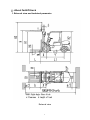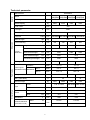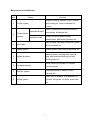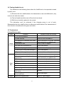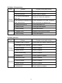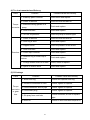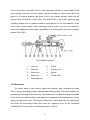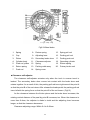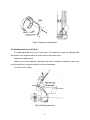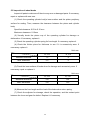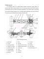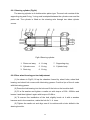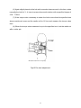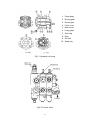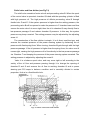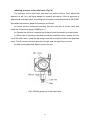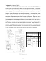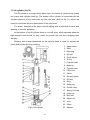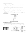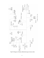
1
PREFACE
The new type BAOLI forklift truck is of internal combustion balance weight type,
which adopts advanced TCM transmission, wide vision mast system, cycloid gear type
powered steering unit, and other advanced technique and equipment. So it is
characterized by high performance, convenient operation, wide vision, flexible
steering, reliable braking, low noise and attractive appearance. It is suitable for
loading and transportation of kinds goods in goods station, port, airport, factory and
store house. It is the ideal machine for realizing mechanization in loading and
unloading. If the forklift truck is equipped with some attachments, its usage sphere will
be wider.
This manual states 2-3.5t forklift truck’s specifications, main assemblies’
construction, working principle, operation and maintenance. It is necessary to read
over the manual before operating or maintaining the forklift trucks. The rules and
notices in this manual should be abided seriously by all of relative personnel to enable
these trucks in optimized working state for long period and bring the highest efficiency.
The partial content in this manual might not correspond with the actual condition
because of technical improvement. Our products are subject to improvements and
changes without notice.
If there is something in the manual you do not understand, ask local dealers for
advice. Suggestion and criticisms are welcome.
Thank you for your trust for Baoli forklifts, we heartily wish you have a merry heart
goes all the way.
CONTENTS
Ⅰ. About forklift truck……………………………………………………………… 1
1. External view and technical parameter…………………………………………
1
2. Characteristic………………………………………………………………………
3
Ⅱ. Safety instruction and operation of forklift truck……………………… 5
1. Handling a new forklift truck………………………………………………………
5
2. Inspection before operation………………………………………………………
5
3. Start and stop of the engine………………………………………………………
6
4. Shipping, loading and unloading, slinging and towing of forklift truck…………
7
5. Parking and storing…………………………………………………………………
9
6. Information of safety operation……………………………………………………
11
7. Caution plate………………………………………………………………………
15
Ⅲ. Periodic inspection and servicing………………………………………… 22
1. General rules on inspection and maintenance…………………………………
22
2. Essentials of servicing……………………………………………………………
23
3. Recommended oil, grease and coolant…………………………………………
24
4. Lubrication system…………………………………………………………………
24
Ⅳ. Construction, principle, adjustment and maintenance of forklift
truck…………………………………………………………………………… 25
…
…
1. Power system…………………………………………………………………………
25
1.1 General description………………………………………………………………
25
1.2 Engine parameter and appropriate truck model………………………………
25
1.3 Inspection and adjustment of engine……………………………………………
26
1.4 Fuel tank…………………………………………………………………………
27
1.5 Precautions of cooling system…………………………………………………
28
2. Mechanical drive system……………………………………………………………
30
2.1 Clutch………………………………………………………………………………
30
2.2 Mechanical drive unit……………………………………………………………
32
3. Hydraulic drive unit……………………………………………………………………
35
3.1 General description………………………………………………………………
35
3.2 Torque converter…………………………………………………………………
37
3.3 Hydraulic circuit……………………………………………………………………
38
3.4 Towing disabled truck……………………………………………………………
39
3.5 Troubleshoot………………………………………………………………………
39
4. Drive system……………………………………………………………………………
42
4.1 General description………………………………………………………………
42
4.2 Procedure for hubs remounted…………………………………………………
42
4.3 Troubleshoot………………………………………………………………………
45
5. Brake system……………………………………………………………………………
46
5.1 General description………………………………………………………………
46
5.2 Master cylinder……………………………………………………………………
46
5.3 Wheel brake………………………………………………………………………
47
5.4 Parking brake lever………………………………………………………………
49
5.5 Inspection of wheel brake………………………………………………………
50
5.6 Troubleshoot………………………………………………………………………
51
6. Steering system………………………………………………………………………
52
6.1 General description………………………………………………………………
52
6.2 Hand wheel………………………………………………………………………
53
6.3 Cycloid gear type powered steering unit………………………………………
53
6.4 Inspection after reassembling the steering system……………………………
54
6.5 Troubleshoot of steering system………………………………………………
54
6.6 Steering axle………………………………………………………………………
55
7. Hydraulic system………………………………………………………………………
58
7.1 General description………………………………………………………………
58
7.2 Hydraulic oil pump………………………………………………………………
58
7.3 Control valve & flow divider………………………………………………………
58
7.4 Hydraulic oil circuit………………………………………………………………
62
7.5 Lift cylinder…………………………………………………………………………
63
7.6 Flow regulator valve………………………………………………………………
64
7.7 Tilt cylinder…………………………………………………………………………
65
7.8 Hydraulic pipe-line………………………………………………………………
66
7.9 Troubleshoot………………………………………………………………………
67
8. Lifting system…………………………………………………………………………
69
8.1 Inner and outer mast……………………………………………………………
69
8.2 Lift bracket…………………………………………………………………………
70
8.3 Fork…………………………………………………………………………………
70
8.4 Roller position……………………………………………………………………
70
8.5 Maintenance and adjustment……………………………………………………
71
9. Electrical system………………………………………………………………………
74
9.1 General description………………………………………………………………
74
9.2 Brief explanation for operation…………………………………………………
75
9.3 Precautions when using the battery……………………………………………
76
9.4 Harness……………………………………………………………………………
77
Product improve suggestion sheet…………………………………………… 85
NOTE……………………………………………………………………………………… 86
EC DECLARATION OF CONFORMITY………………………………………… 87
Ⅰ. About forklift truck
1. External view and technical parameter
External view
1
Technical parameter
General
Manufacturer
KION Baoli
CPC(D)20 CPC(D)25 CPC(D)30
CPC(D)35
CPQ(Y)D20 CPQ(Y)D25 CPQ(Y)D30 CPQ(Y)D35
Model
Power type
Diesel / Gasoline/ LPG
Rated capacity
kg
Load center
3000
mm
500
3000
3500
H
mm
Free lift height
H4
mm
L×W×T
mm
1070×120×40 1070×120×45 1070×125×45 1075×130×45
α/β
deg
6/12
X
mm
484
489
494
500
Length to fork face
L1
mm
2510
2580
2720
2775
Overall width
B1
mm
1150
Mast lowered height
H1
mm
2050
Mast extended height
H3
mm
4040
4272
Overhead guard height
H2
mm
2060
2090
R
mm
Mast tilt angle
Dimension
2500
Lift height
Fork size
Front overhang
Overall
dimension
Turning radius
Hydraulic
Performance
2000
Travel speed
(full load/no load)
140
2170
145
1225
2080
2240
2230
2460
2540
km/h
17 / 19
18 / 19
Shift Ⅰ
km/h
8.5 / 9
8.8 / 9
Shift Ⅱ
km/h
18.5 / 19
18.5 / 20
Mechanical
Lift speed with load
mm/sec
Max. grade ability
%
Service weight
kg
470
430
400
20
3550
3880
15
4380
4750
Front
7.00-12-12PR
28×9-15-12PR 28×9-15-14PR
Rear
6.00-9-10PR
6.50-10-10PR
Wheel & Tyre
Tyre
Front
B2
mm
970
1000
Rear
B3
mm
970
970
Y
mm
1600
1700
85/105
110/135
115/120
135/140
Tread
Wheelbase
Ground clearance
(full load/no load)
Mast
M
mm
Frame
F
2
2. Characteristic
The forklift truck has advantages as follows:
1. The hydraulic steering device makes steering flexible and the double ladder
like steering axle makes the turning radius minor.
2. The braking system employs oil pressure brake, makes it possible to
manipulate conveniently and brake reliably.
3. Employed wide-vision extension type mast, the forklift truck is high intensity.
The forklift truck can be fitted with 2-stage or 3-stage full free lift mast having different
lifting height, even all kinds of the attachments according to the needs of the clients.
4. Hydraulic transmission type forklift trucks are provided with a drive unit
including a torque converter and a hydraulic transmission. They feature the following:
a. Hydraulic torque converter can change the speed automatically with no
limitation and output torque makes the forklift truck have good performance of
drawing.
b. The inching device makes it easy for the drivers to aim the fork to the cargo.
c. At work, for the forklift truck that needs starting and shifting frequently,
achievement of smooth gear shifting control can raise working efficiency, simplify
operation, reduce the driver’s labor intensity and reduce requirement of the driver’s
operation skill.
5. The drive unit of the mechanical forklift truck consists of transmission and
differential. The transmission is provided with a synchromesh mechanism. It makes
the engaged gear avoid striking when shifting, lower the shift noise.
6. The forklift truck can be chosen different height mast and driver’s cab
according to the operating into container or out container.
7. Specific outline adopts streamline design, wider operating vision and larger
driving space. It has advantages such as low noise, vibration damping, dustproof,
comfortable operation, safety and reliability.
3
Main system of forklift truck
No.
Name
Content
engine mounting, system of fuel, exhaust
1
Power system
and cooling (inc. torque converter oil
cooler)
clutch, transmission with synchromesh
Mechanical drive
2
mechanism, differential etc.
Transmission
system
torque converter, power shifted
Hydraulic drive
3
Drive axle
4
Brake system
transmission, differential, gearshift etc.
axle housing, half shaft, wheel hub, brake,
and front wheel etc.
brake cylinder, brake unit, brake pedal etc.
steering wheel, steering shaft, cycloid
5
Steering system
gear type powered steering unit and
steering axle etc.
6
Hydraulic system
7
Electric system
pump, valve, HP oil pipe, LP oil pipe,
connectors etc.
lamps and lanterns, battery, meter,
harness etc.
mast, fork, lift bracket, load backrest, tilt
8
Lifting system
cylinder, lift cylinder, lift chain, mast roller
etc.
4
Ⅱ. Safety instruction and operation of forklift truck
It is important for drivers and managers to remember the principle of “first safety”
and ensure the safety operation as the description of Operation & Service Manual.
Please read this manual thoroughly. This will give you a complete understanding of
Baoli forklift truck and you will operate them correctly and safely.
1. Handling a new forklift truck
The performance and service life of the forklift truck depends heavily upon the
way you handle it during the break-in period. Drive with special caution while
becoming familiar with a new forklift truck.
(1) Always warm up your vehicle before putting it to work irrespective of season.
Don’t run engine at high rpm without load needlessly. Operate the vehicle under the
light load, avoid sudden speeding and braking.
(2) Replace gear oil in the differential and reducer after the new forklift truck
working for 100 hours.
(3) Renew the oil in engine oil pan, transmission, driving axle and hydraulic oil
tank; check and readjust the clearance of the driving and driven gear in the reducer
after the new forklift truck working for 200 hours.
2. Inspection before operation
Please pay attention to the following items in order to make the vehicle working
with high efficiency and lengthen its service life.
(1) The forklift truck adopts the home or imported engine, please read the manual
accompanied with the engine carefully when using and maintenance.
(2) Check the tyre inflation pressure, if doesn’t enough, charge air in time. Check
the bolts of all wheels for tightness.
(3) Check the amount of oil in the working oil tank for sufficiency, the position of
lubrication should be lubricated. The oil level should be at the middle position between
the upper and lower scale marks of oil level meter. The contamination level of the
hydraulic oil should be lower than Grade 12.
(4) Check the radiator, and add antifreeze if necessary.
(5) Check hydraulic oil and brake fluid for leakage. Check if any leak or damage
5
found on the oil pipes, water hoses, vent-pipes and the piping joints, pumps and
valves etc.
(6) Check for all the terminals and plugs in normal state. Check the meters, lamps,
switches and electric circuit if they are running properly.
(7) Check every pedal for free stroke and the levers for looseness and smooth
operation. Check lifting system, actuate the lifting and tilting levers to be certain that
the lift bracket moves up and down properly and the mast can be tilted smoothly.
Check brake system and steering system for flexibility and reliability.
(8) Check the wheel brake: the free stroke of brake pedal is 4-8 mm, when
achieving effective brake, the clearance between the front floor and the pedal should
be more than 20mm.
(9) Check the parking brake: the unload forklift truck can park on 20% slope,
when the parking brake is locked.
(10) Check all connectors and fasteners for looseness.
3. Start and stop of the engine
(1) Start of the engine
(a) First set the shift lever at the neutral position and the parking brake at the
braking position.
(b) When starting, put the key into the start switch, turn it in the counter clockwise,
preheat 15-20 seconds, and then turn it in the clockwise to “START” so the starting
motor works. When your hand is away from the key, it automatically returns to “ON” by
spring force. Every starting time shouldn’t morn than 15 seconds. Restarting should
be after 30 seconds. As the engine doesn’t work after some times starting, should
check and remove the trouble, do not keep the starting motor engaged for a long time.
(c) Following the start of the engine, it’s necessary to set the engine on idle
running for five minutes. Full load operation can’t be started until water temperature of
the engine rises above 60℃.
When the engine is on idle running, you must check water thermometer, oil
manometer, ammeter, fuel measurer, and so on for the data, whether to meet the
specification, and check each pedal for free stoke, braking performance for its reliability,
steering operation for its flexibility, tyre pressure for its conformance to the standard. If
6
there is no trouble, operation may be allowed.
(2) Stop the engine
First set the engine on idle running for five minutes, so as to cool the engine
gradually, and then turn off the ignition switch, so the engine is stopped to work.
Notice:
.While the engine running, does not turn the start switch to “START” position, or
it will damage the starting motor.
.Do not keep the start switch at the “ON” position while the engine is shut down.
This will result in battery discharge.
4. Shipping, loading and unloading, slinging and towing of forklift
truck
(1) Ship the forklift truck
(a) Apply the parking brake when shipping the forklift trucks by container or freight
car.
(b) Fix the mast and the balance weight with steel wire and use jacks to prevent
the forklift trucks from moving in the cabin.
(c) Pay attention to the overall length, width, height when loading, unloading
and shipping and conforming the regulations is necessary.
(d) Single transporting if necessary after disassembling the mast and balance
weight.
(2) Load and unload the forklift truck
(a) Use the plate with enough length, width and strength.
(b) Pull the parking brake and use jacks to stop the wheel.
(c) Fasten the plate on the center of the cabin, there must be no grease on the
plate.
(d) The left and right height of the plate must be equal to make the loading and
unloading smooth.
(e) Don’t change the direction on the plate to prevent the danger.
(f) Reverse the forklift truck slowly when loading it on the freight car.
7
(3) Sling the forklift truck
(a) Only the specially trained personnel can sling the truck.
(b) Sling points should be always at the positions specified in sling nameplate.
(c) The slinging cable must be enough to hang the forklift truck.
(d) Disassembled parts of forklift truck must be slung in the appointed position.
Mast (normal type)
Model
Balance weight
Dimension
Slinging capacity
Dimension
Slinging capacity
(mm)
(kg)
(mm)
(kg)
2.0T
1890×1040×470
>7800
1135×543×950
>1200
2.5T
1890×1040×470
>7800
1135×628×950
>1600
3.0T
1935×1100×470
>7900
1135×720×955
>1800
3.5T
1935×1100×470
>7900
1135×796×998
>2200
Notice:
Dismantling and slinging the component shall not be performed without the
approval of our company. Under special circumstances, the appointed sling
position should be used. The balance weight, fork and mast of the forklift truck all
have their appointed sling position. The above-mentioned data is only for a
reference, which may be adjusted because of configuration or technology
optimization.
(4) Towing of forklift truck
(a) The towing pin is installed below the counter weight. When towing the forklift
truck, first extract the pin and fasten a steel wire, then install the pin back.
(b) When towing the forklift truck, release the hand brake lever.
(c) The towing pin only used for following situation, while the forklift truck can’t
move or while transporting the forklift truck.
(d) Fasten the towing steel wire at the appointed position.
(e) Don’t apply capacity abruptly when towing the forklift truck.
(5) Repair the broken-down forklift truck
If the forklift truck broken-down suddenly during using, drag it away and repair in
time to avoid hindering other vehicles or workers.
8
5. Parking and storing
(1) Safe parking
(a) Park your forklift truck on a level ground preferably in a wide area. If parking
on a slope is unavoidable, pull the parking brake device and block the wheels to
prevent accidental roll. The forklift truck is forbidden parking on a steep slope.
(b) Park your forklift truck in the area where designated or traffic conditions permit.
If necessary, put a signpost or signal lights around the truck.
(c) Park your forklift truck on the solid ground. Avoid soft ground, deep mud or
slippery surfaces.
(d) If you can not lower the forks on the ground due to break-down of the lifting
system, put a warning flag to the fork end and park in the traffic conditions permitting.
(2) Storing
·Before storing
Before storing your forklift truck, clean it thoroughly and perform inspection using
the following procedures.
(a) Wipe away grease, oil, etc. adhering to the body of the truck with waste cloth
and water, if needed.
(b) While washing the body of the truck, check general condition of the truck.
Especially check the truck’s body for recess or damage and tyres for wear and nails or
stones in the tread.
(c) Fill the oil tank up with the appointed fuel.
(d) Check for leakage of hydraulic oil, engine oil, fuel or coolant.
(e) Apply grease where needed.
(f) Check for looseness of hub nuts and cylinder piston rod joints. Check the
surface of piston rod for damage.
(g) Check mast rollers to see that they rotate smoothly.
(h) Full oil into the lift cylinders by lifting the lift cylinders at the full stroke.
(i) In cold weather, don’t draw off long antifreeze, if there is cooling water, run it
away.
·Daily storage
(a) Park the forklift truck at a specified place and block the wheels.
(b) Place the shift lever in the neutral position and pull the parking brake lever.
9
(c) Put the key switch in “OFF” position and turn off the engine, operate the lever
of the control valve several times and release the residual pressure of the cylinder or
pipes.
(d) Remove the key and keep it in a secure place.
·Long time storage
Perform the following service and checks in addition to the “Daily storage”
service:
(a) Taking the rainy season into consideration, park the truck at a higher and hard
ground.
(b) Apply antirust oil to the exposed parts such as piston rods and shafts which
tends to rust.
(c) Cover components which may be caught with humidity.
(d) The truck should be operated at least once a week. Fill the cooling system, if
cooling water is discharged. Remove grease from the piston rods and shafts. Start the
engine and warm up thoroughly. Move the truck slowly forwards and backwards.
Operate the hydraulic controls several times.
(e) Avoid parking on soft grounds such as asphalted road in summer.
·Operate the forklift truck after long time storage
(a) Remove antirust oil from the exposed parts.
(b) Discharge the engine oil in crankshaft case of the engine, discharge the gear
oil or hydraulic transmission oil in differential and gear box, after cleaning up then
renew oil.
(c) Discharge foreign matter and water from the hydraulic reservoir and fuel tank.
(d) Remove the cylinder cap, the valves and the rocker shafts, check for the
clearance in normal data.
(e) Add cooling fluid to specified level.
(f) Perform pre-operation checks carefully.
(g) Warm up the engine before operation.
Warning:
If at any time your forklift truck is found to be in need of repair, defective, or in any
way unsafe, the condition should be reported to the supervisor, and the truck should
be taken out of service until it has been restored to safe operating condition.
10
6. Information of safety operation
(1) The forklift truck belongs to special equipment. Only trained and authorized
operator shall be permitted to operate and service the truck.
(2) Wear the safety guards, such as clothing, shoes, helmet and gloves while
operating the truck.
(3) When operating the truck, observe and follow all nameplates stuck on the
truck. The nameplates must be replaced if lost or damaged.
(4) Daily maintenance should be done before or after using the truck. Anytime
you find that the truck is not functioning normally, operation of the truck should be
halted and check or repair at once.
(5) When the distance between the gravity center of loads and the fork arms is
500mm, the max. capacity is the rated capacity. When the distance exceeds 500mm,
the capacity shall be reduced according to the load chart. Overloading is strictly
prohibited.
(6) Operate your forklift truck on a hard ground. Operate on other ground, the lift
capacity and travel speed must be decreased. Wipe off the oil and grease from the
floor.
(7) If the forklift truck is equipped with attachment, its usage sphere will be wider,
but its allowable load and stability is reduced. The attachment and special device is
not to be diverted to any other purpose. It’s very dangerous to rebuild the attachment.
Please read the additional instruction we supplied and operate the truck following it
strictly.
(8) Users select “Lengthening fork” in order to carry widening loads. Pay much
attention not to overload and observe the allowable load and the capacity chart stuck
on the truck. Careful driving should be taken when traveling and turning.
(9) The unloaded forklift truck with attachment should be operated as a loaded
truck.
(10) Connect the power and turn on the key switch, select the position of direction
switch, check the truck for normal operation by turning steering wheel, depress the
speed-adjusting pedal softly to keep proper acceleration.
(11) During operation, pay attention to the performance and condition of the
system of machinery, hydraulic, electric and speed-adjuster etc.
(12) When operate one lever, pay attention not to shift another lever. Don’t
operate the lever at any position out of the driver’s seat.
(13) The shift distance of control valve lever can control the speed of the lifting or
descending of the goods. When the goods are lifted or descended, the initial speed
11
shouldn’t be too fast in either case.
(14) When tilting the mast forward or backward to the limit or lifting the fork to the
maximum height, return the directional lever to neutral.
(15) The starting, turning, driving, braking and stopping of the truck should be
done smoothly. When turning on the humid or slippery road, the truck should be
decelerated.
(16) Because the forklift truck turns by the rear wheels, the end counterweight
may swing widely when turning. Use care in narrow aisles and other workplaces.
(17) Operate the forklift truck smoothly, don’t jerk the steering wheel. Avoid
sudden stop, acceleration, stop or turn. In the case of improper operation, the truck
will turn over. In case of this, the driver must keep calm, don’t jump off the truck. The
driver must hold tightly the control wheel with two hands; meanwhile, his body must
incline in opposite direction of truck’s turning over.
(18) Turning, lateral or deflective traveling shall not be taken on a slope. It could
cause overturning of the truck, it is very dangerous. On a slope, drive the truck with
load forward to ascend and backward to descend. When the truck goes down on a
slope, drive slowly with the brakes on. Make sure that the engine should not be shut
down when traveling on a slope.
(19) The stability of the truck is influenced by the wind-force during outside
operation, you must notice specially.
(20) Be careful and slow driving over a dock or temporary paving slab.
(21) Insert forks deeply under goods. Adjust fork’s distance according to the
dimension of goods. Make the loads distribute on the forks evenly to avoid tilt and
slide of goods.
(22) Don’t pick the loads with single fork. Fork can not be used to pull out any
embedded goods, if necessary, the pulling force should be estimated.
(23) Don’t handle unfixed or loose goods. Be careful to handle bulky goods. To
prevent the collapse of stacked goods, tighten them. Forbid loading loose or little
volume goods without pallet.
(24) When loading the goods, lower the forks to the floor. After the fork inserting
stacked goods, the fork arms should be in contact with the goods. Drive the truck with
mast tilting back for stabilizing the load. Before traveling, raise the forks for
200mm-300mm from the floor.
(25) When handling bulky loads which block your view, operate the forklift truck in
reverse or have a guide.
(26) While mast’s lifting and lowering, anyone is absolutely prohibited from
12
standing under the lift bracket or being lifted with forks. Never permit anyone to stand
or walk under upraised forks.
(27) When lifting the load, according to the weight of the load, accelerate properly
and then pull the lifting lever.
(28) The load descends for the gravity, at this time, the engine must be in idle
position, and the lever must be pulled slowly to prevent the load from sudden falling.
(29) When loading and unloading goods, keep the mast vertical and the truck is in
braking state.
(30) Load should cling to the load backrest. Do not handle the load which
exceeds height of the backrest, or else there is a danger of load’s falling against
operator.
(31) When travel with load, don’t tilt mast forward, don’t do handling. Don’t brake
abruptly to prevent goods from slipping off the forks.
(32) It is necessary to brake before tilting the mast forward or backward. It’s also
necessary to decelerate and tilt forward slowly so as to prevent the goods from
slipping off the forks.
(33) Don’t make a sudden braking when the truck traveling with loads.
(34) Drive the forklift truck to the stacked goods at a low speed, at the same time,
pay much attention to sharp and hard objects near the goods, otherwise, the tyres will
be pricked.
(35) Pay attention to pedestrian, obstacle and bumpy road when driving. Pay
attention to the clearance over the forklift truck.
(36) Keep your head, hands, arms, feet and legs within the confines of the cab.
Never allow other persons on the forklift truck.
(37) Tilt the mast of the high lift forklift truck as backward as possible when
operating the truck. Use minimum forward and backward tilt when loading and
unloading. It is dangerous to travel or turn when lifting the goods at high levels.
(38) It is noted that the goods will fall down when the forks of the truck with lifting
height more than 3m lift, take the protection measures if necessary.
(39) Before the truck decelerating and stopping, don’t change gear to reverse
shift, so as to ensure the safe loading.
(40) When the truck stops and the engine is on idle position, the mast must be
tilted backward. You shouldn’t leave the truck with idling engine or hanged goods
unattended.
(41) When adding fuel, make the driver leave the truck and the engine flameout.
Don’t ignite when checking the level of fuel tank.
13
(42) Don’t open the radiator cap when the engine is very hot.
(43) After one day’s working, the fuel tank should be added oil to prevent the
humidity in the fuel tank from becoming the blob and then interfusing the fluid.
(44) When leaving, engage the hand brake, lower the forks on the ground and let
the shift lever to neutral, make the engine flameout or cut down the electric supply. If
parking on a slope with smaller gradient, apply the parking brake and block the wheels.
The truck is forbidden parking on a slope with bigger gradient.
(45) Don’t adjust the control valve and relief valve at will to prevent the damage of
hydraulic system and its components because of excessive pressure passing them.
(46) Tyres should be inflated according to the pressure value specified in the
nameplate of “Tyre Pressure”.
(47) Check the chains periodically to make sure that good lubrication condition
exists between the chain elements, the degree of tightness between left and right
chain is identical. If the variation value of the chain pitch exceeds 2% standard value,
it indicates that the chains have been worn excessively, replace it immediately.
(48) The overhead guard is main part which is strong enough to meet safety
standard, and protect the operator from falling materials. It’s very dangerous to
dismantle or rebuild the overhead guard, because these conditions could lead to an
accident.
(49) A load backrest shall be used as protection against back falling objects on
the fork. It’s very dangerous to dismantle or rebuild the load backrest, because these
conditions could lead to an accident.
(50) You can’t change or add other working equipments on the truck without our
company’s permission, or the rated capacity and safety operation will be affected.
(51) Keep safety when serving on high position.
(52) The forklift truck must be operated under the following environment: below
an elevation of 1000 meters and temperature between -20℃and 40℃, relative
humidity is 95%. Careful operation must observe under other adverse circumstances.
(53) Because of the danger for the people, the forklift is forbidden operating in
airtight space, or you may be choked by the tail gas. The tail gas’s exhausting
standard shouldn’t be lower than the no-load mechanical vehicle exhaust standard
ruled by the nation that users are in. If in Europe nation, the adopted tail gas’s
exhausting index should be applied Europe StageⅢA standard.
(54) According to the Directive 2000/14/EC and based on EN12053 standard,the
noise pressure level at the operator’s position and the measured sound power level
and the guaranteed sound power level is referred to the following table. But the noise
14
of the forklift truck may fluctuate due to different operation and the influence of the
external environment.
(55) The driver feels the vibration of the forklift truck when operating and traveling
the forklift truck.. According to ISO3691 and based on EN13059 standard. The
vibration of the forklift truck fluctuates according to environment condition. In normal
working condition, the vertical direction acceleration mean value from the seat to the
operator by testing is in the following table. But the vibration frequency felt by the
driver depends on the working condition (etc. road, operation method), so the actual
vibration frequency must be determined according to environment condition when
necessary.
(56) To prevent the fire, accident or other unpredictable event, prepare the fire
extinguishers in advance and operate them according to the instructions.
The noise pressure
level at the operator’s
Model
position
The vertical
The measured sound
The guaranteed
direction
power level
sound power level
acceleration mean
value from the seat
EN12053
EN12053
2000/14/EC
to the operator
CPCD20
85 dB(A)
105 dB(A)
107 dB(A)
0.76 (m/s )
CPCD25
86 dB(A)
104 dB(A)
107 dB(A)
0.72 (m/s )
CPQD20
85 dB(A)
103 dB(A)
105 dB(A)
0.86 (m/s )
CPQD25
85 dB(A)
103 dB(A)
105 dB(A)
0.84 (m/s )
CPCD30
87 dB(A)
105 dB(A)
107 dB(A)
0.91 (m/s )
CPCD35
86 dB(A)
104 dB(A)
107 dB(A)
0.84 (m/s )
CPQD30
86 dB(A)
103 dB(A)
105 dB(A)
0.85 (m/s )
CPQD35
87 dB(A)
104 dB(A)
105 dB(A)
0.87 (m/s )
2
2
2
2
2
2
2
2
7. Caution plate
The caution plates attached on the vehicle indicates the operating method and
instructions. Before driving it, please be sure to read them thoroughly. If the caution
plate drops, stick it again. When maintaining, check if the caution plate is complete
and the writing is legible, if necessary, please replace them.
(1) Safety mark (People are forbidden to stand on or down the fork.)
15
(2) General information when operating
(3) Nameplate of forklift truck
(4) Lubrication system
(5) Capacity chart
16
(6) Inspections before starting
(7) Adjust parking brake
(8) Add hydraulic oil
(9) Add fuel (gasoline)
(10) Add fuel
17
(11) Add antifreeze
(12) Tyre safety decal (charging tyre)
(13) Tyre pressure decal (charging tyre)
2-2.5t forklift truck
3-3.5t forklift truck
(14) Sling point indication
18
(15) Sling decal
(16) Forbid entering into the space behind the mast
(17) Forbid conveying person
(18) Hand caution decal
(19) Fan hurting hands
19
(20) Hood crushing hands
(21)Belt pulley thumb hand decal
(21) Overturn caution decal
20
Ⅲ. Periodic inspection and servicing
During operating the forklift truck, it is necessary to operate carefully, service and
maintain periodically to make the forklift truck keep in good condition.
1. General rules on inspection and maintenance
(1) Only use genuine parts provided by our company.
(2) Only use genuine or recommended oil when replacing or adding.
(3) Clean oil fillers and grease fittings with a brush or waste cloth before adding
oil or grease.
(4) Checking oil level and adding oil should be made with the truck parked on a
level ground.
(5) Preventive maintenance should be done in an orderly manner and due care
taken not to injure yourself.
(6) If any damage or fault is found, stop the truck and report the condition to the
manager. Do not operate the truck until it has been repaired completely.
.Regular inspection
(1) Check the seal and the reliability of the hydraulic system.
(2) Check the reliability of the steering and braking system.
(3) Check the reliability of mast, driving axle and steering axle connecting with the
frame.
(4) Check all wheels for tightness.
.Irregular inspection
(1) Check the reliability of each welding joints of the mast, frame and so on.
(2) Check the reliability of connecting joints of steering cylinder, joint plate and
gimbals etc.
(3) Check all pipes and hoses for any leakage and breakage.
(4) Check the performance of the traveling brake and the parking brake.
Caution:
.Only trained and authorized serviceman shall be permitted to service and
repair the truck.
.When checking and maintaining the forklift truck, do not use the mast or
the load backrest instead of a ladder, these actions will lead to a dangerous
condition unexpectedly.
21
2. Essentials of servicing
(1) Some critical components must be replaced according to demands
periodically. Use genuine parts only.
(2) Use the same model oil only when replacing or adding.
(3) If any damage or fault is found, stop the truck and report the condition to the
manager. Do not operate the truck until it has been repaired completely.
Periodic service and maintenance must be done according to the following list
after using the forklift truck.
No.
Item
Contents
Period (hrs.)
1
Bearing, steering wheel
Replace grease
1000
2
Bearing, drive wheel
Replace grease
1000
3
Steering link lever
Replace grease
1000
4
Parking brake lever
Add grease
200
5
Pin, foot brake
Add grease
200
6
Drive axle body
Replace gear oil
2400
7
Braking oil
Add
8
Pin, tilting cylinder
Add lubricating grease
400
9
King pin, knuckle
Replace grease
1000
10
Hydraulic tank and filter
Clean
1000
11
Hydraulic oil
Replace
1000
12
Lift chain
Replace
3000
13
H. P. hose
Replace
3000
14
Switch, hydraulic motor
Clean photoelectric
coupler
200
15
Brush, traction motor
Check
1000
16
Brush, hydraulic motor
Check
1000
17
Brush, steering motor
Check
1000
Remark
Whenever
necessary
If damaged,
replace it.
Notice:
When serving and checking the truck, do not use the mast or the load
backrest instead of a ladder, these actions will lead to a dangerous condition
unexpectedly.
22
3. Recommended oil, grease and coolant
Brand or code
Name
Quantity
Domestic
Overseas
90#
JISK2202/2#
Gasoline
Refer to diesel engine manual or
JISK2204/2# (general region)
select GB252-81 light diesel:
JISK2204/3# (cold region)
Winter -10#~-35# Summer 0#
Refer to engine manual or
SAE10W(Winter)
Engine oil select according to GB5323-85 or
SAE30(Summer)
working condition
Hydraulic oil
N32# or N46#
ISOVG30
Diesel
60L
55L
45L
Torque
converter oil
6# / 8# Torque converter oil
SAE10W
20L
Gear oil
85W/90
SAE85W/90
18L
DOT3 Compound brake fluid
3# Lithium base grease
JISK2220/2#
(drop point 170)
0.6L
Brake fluid
Lubricant
grease
Coolant
Water or -35℃ Long Life Coolant (FD-2)
Filled
The oil quantity listed in above table is approximation, the detailed value when
operating is inspected according to the meter or corresponding gauge.
Adding oil, grease and coolant should follow relevant automobile standard. The
waster of the truck must be reclaimed obeying the relevant laws and regulations.
Incorrect treatment will pollute water, soil and atmosphere etc.
It is necessary to wear a helmet, safety shoes and working clothes to avoid
contacting with body when adding. Once the greasy dirt adhered on the skin, wash it
with clean water and soap, it is forbidden to wash with gasoline or kerosene.
4. Lubrication system
No.
Position
Point
1
Support of steering device
Both end joints of steering
cylinder
Bearing of knuckle
Bracket of foot control
Pin of tilt cylinder
Lever head of tilt cylinder
Support bushing of mast
Lift roller of fork bracket
2
Lime grease
2
Lime grease
4
1
2
2
2
8
Lime grease
Lime grease
Lime grease
Lime grease
Lime grease
Lime grease
2
3
4
5
6
7
8
Brand
50
Time (hours)
100 500 1000
+
+
+
+
+
+
+
+
Note: About lubrication of the engine, refer to the ENGINE OPERATION MANUAL.
23
Ⅳ. Construction, principle, adjustment and maintenance of
forklift truck
In order to keep good condition of your forklift truck, you must have an intimate
understanding of the construction, principle, adjustment and maintenance of the
forklift truck. When finding damage or fault with the truck, stop operating the truck and
inform a professional serviceman. Use genuine parts of our company for replacement.
1. Power system
1.1 General description
Power system consists of the engine, fuel system, intake system, cooling system
and exhaust system. The engine is connected with the frame by rubber cushion to
avoid vibration. The engine, torque converter, transmission case, transmission shaft
and drive axle are assembled into a single unit.
For the construction and adjustment of engine, please refer to the operation and
maintenance manual of engine.
1.2 Engine parameter and appropriate truck model
Engine model
Diesel engine
Xinchang
Rated output Rated torque
Kw/r.p.m
N.m/r.p.m
No. of cylinderDisplacement
Bore×stroke
L
mm
BPG490
37/2650
148/1900
4-90×100
2.54
CPC(D)
20/25/30-X1
BPG495
42/2650
174/1800
4-98×105
2.98
CPC(D)
30/35-X2
BPG498
45/2500
191/1600
4-98×105
3.168
CPC(D)
30/35-X3
C240PKJ
34.5/2500
139/1800
4-86×102
2.369
CPC(D)
20/25/30-W1
4JG2PE
44.9/2450
186.3/1600
4-95.4×10⁷
3.059
CPC(D)
25/30/35-W2
4TNE92
32.8/2450
149/1600
4-92×100
2.659
CPC(D)
20/25-Y1
4TNE98
44.3/2300
206/1700
4-98×110
3.319
CPC(D)
25/30/35-Y2
4G64
-31ZG
37/2500
161/1600
4-86.5×100
2.350
CPQ(Y)D
20/25/30-H1
K21
31.2/2250
143/1600
4-89×83
2.065
CPQ(Y)D
20/25-H2
K25
37.4/2300
176/1600
4-89×100
2.488
CPQ(Y)D
20/25/30/35-H3
ISUZU
Yanmar
Gasoline
engine
Mitsubishi
Truck model
Nissan
24
Parallel table for engine and forklift model which is coincidence and stuck with
CE label:
The guaranteed
Sound power
level LwA(dB)
2000/14/EC
Exhausting
2004/26/EC
CE CONFORMITY
2006/42/EC
C240PKJ
106
StageⅢA
yes
4TNE92
107
StageⅢA
yes
4TNE98
107
StageⅢA
yes
4G64
-31ZG
105
yes
K21
105
yes
K25
105
yes
Gasoline engine Diesel engine
Engine model
ISUZU
Yanmar
Mitsubishi
Nissan
Truck model
CPCD
20/25/30-W1
CPCD
20/25-Y1
CPCD
25/30/35-Y2
CPQD
20/25/30-H1
CPQD
20/25-H2
CPQD
20/25/30/35-H3
Note: The sound power level LWA according to 2000/14/EC standard, the
exhausting according to 2004/26/EC standard. The forklift with gasoline engine is
not referred in 2004/26/EC standard presently.
1.3 Inspection and adjustment of engine
In order to keep good condition of your truck, you must carry out periodic
inspection and adjustment of power system.
(1) Regularly clear the dust of air cleaner.
(2) Regularly replace oil filter and fuel filter.
(3) Check and apply the coolant periodically.
(4) Periodic inspection of throttle valve and injection pump.
(5) Check fan belt for tension and all fasteners.
Note:
Always check the exhaust gas of the engine during using the forklift truck.
Especially after maintaining the engine, it’s necessary to verify the discharge indicator
ensure that discharge value is fit for the national standard, so as to minimum damage
to the person and environment.
1.4 Fuel tank
The fuel tank is a welded construction integrated with the truck frame. It is located
on the left side of the truck frame. The tank cover with a fuel sensor is located on the
top surface of the tank. The fuel tank design is almost the same for the gasoline and
25
diesel engine type trucks. The difference is that the gasoline type is fitted with oil
suction pipe and the diesel type with oil return pipe.
1.4.1 Fuel sensor
The fuel sensor is designed to convert the remaining amount of fuel electric
current. See Fig1.1.
Fig1.1 Fuel sensor
1.4.2 Maintenance of the fuel system
Once every 100 hours operation, it is required to maintain the fuel system
according to the methods as follows. Once every 600 hours operation, it is required to
clean the fuel tank.
(1) Fuel filter
The fuel filter is used to clean the fuel applying to the engine. It is installed in the
fuel pump (for gasoline engine) or on the fuel tank (for diesel engine). The fuel filter
used in diesel engine can also separate water from fuel.
▲ Gasoline engine
(a) Once every 300 hours operation, replace the filter wholly.
26
(b) Loosen the circle wheel and remove the cap.
(c) Loosen the nut and take the filter element out.
(d) Clean or replace the filter element.
(e) After reassembly of filter, start the engine to feed gasoline into filter bowl and
check for leaks.
▲ Diesel engine
(a) Once every 600 hours operation, it is required to replace the filter assembly.
(b) Apply several drops of fuel to the around of the new filter’s seal before
installation, it should be screwed 2/3 circles again when the filter’s seal touches the
body of engine.
(c) When the warning lamp is on, drain all the water by loosing the draining
switch.
Note: Turn off the draining switch after draining water.
(2) The cleaning of fuel tank
Once every 600 hours operation, the fuel tank should be cleaned. As for the
gasoline forklift truck, it is required to take care of fire when cleaning.
1.5 Precautions of cooling system
(1) During using the forklift truck, if the temperature of the radiator or coolant is
too high, don’t open the cap of the radiator immediately. To find the reason for boiling,
use extreme care when removing the cap, the sudden release of pressure can cause
a steam flash which would cause a serious personal injury. Lower the running speed
of the engine to moderate speed, after the cooling system cooled then turn to idle
speed, loosen cap slowly to allow steam to escape, the cap can be removed. After
that, make sure the cap is tightened securely.
(2) Check the radiator coolant reservoir fluid level. It should between FULL and
LOW mark. Add the same type coolant to specified level if necessary. The coolant
can be used all the year round.
(3) Put the coolant on a safe place and mark “Dangerous Matter” for its toxicity. If
swallowed by accident, take the emergency first aid and consult a physician
immediately.
(4) According to variety working condition, periodic wiping away the dirt adhering
to the surface of the radiator with detergent, compressed air or high pressure water
(pressure less than 4kg/cm2) is necessary.
27
2. Mechanical drive system
2.1 Clutch
Type
Dry single plate type
Operation
Foot-pedal type
Friction piece outer diameter
275mm
Friction piece inner diameter
175mm
Friction piece thickness
8.9±0.3mm
Surface area
354cm2
Weight
12.5kg
2.1.1 General description
The clutch consists primarily of clutch housing, friction pieces, jib and pressure
plate assy. It transmits or cuts off the power from the engine to the gear box. The
structure of clutch is referred to Fig2.1.
1. Housing
2. Clutch friction piece
3. Pressure plate
4. Pressure spring
5. Spring
6. Hub
7. Shaft
8. Bearing
9. Release lever
10. Release bearing
11. Release bearing sleeve
12. Bolt
13. Nut
14. Separating fork
15. Cover
Fig2.1 Clutch
28
2.1.2 Maintenance
A. Adjustment of clutch pedal
(1) Remove the floor board.
(2) Loose the lock-nut of the stopper bolt.
(3) Turn the stopper bolt left and right to adjust the height of the clutch pedal.
(4) Screw the lock nut tightly and fit the floor board.
B. Replacement of friction pieces
(1) Remove the clutch cover.
(2) Press the clutch pedal and move out the pressure plate with liftout bolt. (See
Fig 2.2)
(3) Turn the slide bolt left to let the drive shaft go into the transmission.
(4) Disassemble the stopped bolt of the clutch cover, remove the friction pieces.
(5) Install the new friction pieces with the longer spline boss pointing toward the
transmission.
Note: Make sure that the spline couple of drive shaft has corresponded with
the spline.
(6) The tighten torque of the slide bolt: 10.9-12.1kg.m.
(7) Install the clutch housing on the flywheel.
(8) Press the clutch pedal and remove the liftout bolt.
(9) Check the free stroke of clutch pedal and adjust it if necessary. (Free stroke:
10mm)
(10) The distance between the release lever and clutch bearing seat should be
3mm.
Fig2.2 Liftout bolt
29
2.2 Mechanical drive unit
Manual-shift, slide type
synchromesh mechanism
FWD 2
BWD 2
Type
Transmission
Shift No.
Gear
Ratio
Reducer
Differential
FWD 1st/2nd
3.253/1.407
BWD 1st/2nd
3.204/1.386
Reduction gear
Spiral bevel gear
Reduction ratio
2.1
Reduction gear
Spur gear
Reduction ratio
6.182
Differential gear
Bevel gear
Oil amount
8L
Weight (without oil)
165kg
2.2.1 General description
The drive unit of clutch type truck consists of transmission and differential.
The transmission is provided with a synchromesh mechanism. (See Fig2.3)
2.2.2 Reducer and differential
The reducer located in the front of the transmission is used to reduce the speed
and increase the torque from the output shaft of the transmission and transfer them to
the differential. It consists primarily of a small spiral bevel gear assembled on the
output shaft and a pinion shaft splinted with a big spiral bevel gear. Both ends of the
pinion shaft are supported by tapered roller bearing. Several shims are installed
between the case and bearing covers to adjust the clearances between them.
The differential is housed in the front portion of the differential the front end of
which is connected with the axle housing. The differential case is of splitting type. The
differential includes two halfshaft gears and four planer gears. The thrust washers are
installed between the differential case and each gear, which makes the clearance
among gear pairs is proper. The planet gears are supported by planet gear shaft Ⅰ
and Ⅱ. The gear shaft Ⅰ and ring gear 1 are fixed to the differential case respectively
with column pin and hinged bolt.
The power from the transmission is transmitted through the reduction gear,
differential, halfshaft gear and halfshaft to driving wheels.
The structure of the reducer and differential is referred to Fig2.4.
30
1. Snap ring
Fig 2.3 Transmission
13. O-ring seal
25. Forward gear
2. Snap ring
14. Slide bolt
26. Needle bearing 38. Shift lever
3. Ball bearing
15. Retainer, bearing
27. Reverse gear
39. Shift fork
4. Spacer
16. Drive shaft
28. Clutch hub
40. Switch, neutral
5. Ball bearing
17. O-ring seal
29. Spacer
41. Shift fork
6. Drive gear
18. Drive gear
30. Needle bearing 42. Switch, reverse lamp
back-upseal
lamp
31. Shaft
43. O-ring
7. Needle bearing 19. Lock nut
37. Tapered roller bearing
8. Combined
20. Adjusting nut
32. Backward gear 44. O-ring seal
9. bearing
Needle bearing 21. Tapered roller bearing 33. Gear, low speed 45 Collar
10.Spacer
22. Ball bearing
34. Clutch hub
11. Ball bearing
23. Retainer, bearing
35. Gear, high speed
12.Oil seal
24. Ball, steel
36. Ball bearing
31
Fig 2.4 Reducer and differential
1. Gear ring
5. Shim
9.
2. Pin
6. O-ring seal
10. Gear
14. Planet gear
3. Ball bearing 7. Bearing cover
11. Spacer
15. Shim
4. Side gear
12. Pinion shaft
16. Gear shaft
8. Tapered roller bearing
32
Adjusting shim 13. Column pin
3. Hydraulic drive unit
Type
Torque converter
Charging pump
Three elements, single stage, two phases
Torque ratio
3
Set pressure
0.5~0.68 MPa
Type
Inner-mesh gear pump
Flow rate
Hydraulic
transmission
27 L/min(2000rpm,1.5MPa)
Type
Power shifted
Speed ration
1.35/1.35
(FWD/BWD)
Friction piece:
Ф125×Ф80×2.7 (mm)
Hydraulic
O.D.×I.D.×T.
clutch
Friction area
71cm2
Set pressure
1.1~1.4 MPa
Weight
165kg
Oil amount
7L
Oil type
6# or 8# Torque converter oil
3.1 General description (Fig3.1)
The hydraulic transmission case used in the hydraulic drive type truck is
consisted of a torque converter and a power gear-shifting transmission.
(1) With an inching valve, the inching operation can be done under the condition
that the engine runs at both high and low speed.
(2) Each of two hydraulic clutches is provided with three pairs of steel plates and
high quality friction pieces specially-treated, so as to improve the durability of friction
surface.
(3) One-way clutches in the torque converter are used to increase the efficiency
for power transmission.
(4) High quality oil filters is helpful to prolong the life of the torque converter.
33
Fig3.1 Hydraulic drive unit
1. Forward clutch
18. Safety valve cover
35. Output gear
2. Oil filter
19. Inner-hexagon plug
36. Idler shaft
3. Backward clutch
20. Plug
37. Single-row radial ball bearing
4. Single-row radial ball bearing 21. Spring pin
38. Bearing nut
5. Seal ring
22. Shift arm
39. Single-row tapered roller bearing
6. O-ring
23. Transmission case cover
40. O-ring
7. Charging pump
24. Shift shaft
41. Oil seal
8. Oil seal
25. O-ring
42. Single-row tapered roller bearing
9. Impeller
26. Haft-round key
43. Output shaft
10. Guide wheel
27. Clip ring for hole
44. Supporting piece
11. Turbine
28. Single-row radial ball bearing 45. Single-row radial ball bearing
12. Spring plate
29. Single-row radial ball bearing 46. Inner-hexagon plug
13. Inching valve
30. O-ring
47. Cover
14. Control valve
31. Snap ring
48. Bolt
15. Piston
32. O-ring
49. Switch, reverse lamp
16. Spring
33. Idler
50. Drain plug
17. Oil inlet cover
34. Oil filter
34
3.2 Torque converter (Fig 3.2)
The torque converter mainly consists of an impeller, a turbine and a guide wheel.
The liquid, from the impeller driven by an input shaft, is jetted along its leaves to
leaves of the turbine to transmit the torque to the output shaft (Mechanical energy is
changed into kinetic one). And the flowing direction of the liquid from the turbine wheel
is changed by the idler pulley to cause partial liquid return the impeller at an angle and
produce so large reaction torque driving the idler pulley that the value of output torque
is more than that of input torque by the value of the reaction torque. When the turbine
speed keeps on increasing up to speed of the impeller, the change rate of the flow
angle slows down and the value of the output torque keeps on decreasing until the
liquid flows into the leaves of the idler pulley in opposite direction. When original
reaction torque acts in the opposite direction, the torque value of the output shaft is
less than that of the input shaft. To prevent this, a one-way clutch is fitted in the idler
pulley, causing the idler pulley freely rotate on this case. The way of torque-converting
can be used to ensure efficient and smooth work of the torque converter.
The torque converter, filled up with the torque converter oil, in the drive unit is
driven by an engine through a spring plate and flywheel on the engine. A charging
pump is driven by a driving gear which is supplied by the pump. The power is
transmitted to the transmission through a turbine shaft spliced to the turbine.
1. Spring plate
2. Turbine
3. Impeller
4. Idler pulley
5. One-way clutch
Fig3.2 Torque converter
35
3.3 Hydraulic circuit (See Fig3.3)
After the engine is started, the charging pump inhales the oil from the oil tank.
The pressure oil from the pump serves two parts for hydraulic clutches and torque
converter.
The oil necessary to operate the hydraulic clutches is divided into two circuits
through the pressure valve (set pressure of 1.1-1.4MPa): one circuit flowing to the
torque converter via. a relief valve (set pressure of 0.5-0.7MPa) and another to the
inching valve and the slide valve. The oil out of the torque converter is cooled by an oil
radiator and used to lubricate the hydraulic clutches and finally returns to the oil tank.
In the neutral, the circuit from the slide valve to the clutches is intermitted, and the
pressure valve is opened to let the oil only flow into the torque converter. When the
slide valve lies at its forward or backward position, the circuit form the slide valve to
either the forward clutch or the backward clutch is closed accordingly, thus causing
corresponding clutch come to work. When a clutch is at work, another must stop
working, i.e. its spacers and friction pieces must be disengaged each other and be
lubricated and cooled. When the inching valve is operated through stressing the
inching pedal, apart or most of the oil in the clutches flows into the oil tank through the
inching valve rod. The oil circulation for the torque converter then is the same as that
in the neutral.
1. Charging pump
2. Oil filter
3. Relief valve
4. Oil filter
5. Pressure valve
6. Oil radiator
7. Torque converter
8. Adjusting valve
9. Slide valve
10. Inching valve
11. Switch
12. Backward clutch
Fig3.3 Hydraulic circuit
13. Forward clutch
36
3.4 Towing disabled truck
Pay attention to the following items when the forklift truck to be repaired is towed
by other truck:
(1) Remove the drive shaft between the transmission case and differential. (only
for the truck with drive shaft)
(2) The half shaft should be took off from the front wheel.
(3) Shift lever should be placed in the neutral.
The lubrication can’t be achieved if the charging pump is out of work.
Disassemble the drive shaft for there is adherence performance if the transmission of
drive wheels is transferred to the gear and clutch.
3.5 Troubleshoot
(1) Insufficient power
Parts
Problem
Possible cause and remedy
A. Too low oil pressure
1. Lower oil level
Check oil level and add oil
2. Air entering in resulting from loose
connections
Check connection or oil pipe. Retighten
each connection or replace seal.
Torque 3. Blocked oil filter
converter
4. Oil can not be pumped out
Check, clean or replace.
Check and replace
5. Deformed spring of relief valve
Check tension of spring
6. Seal ring or O-ring seal damaged
Check and replace
B. Fly wheel damaged
Check oil, if have dirt, replace it.
A .Unsuitable oil or air bubble in oil
Check oil
1. Air entering in resulting from loose
connections
Check connection or oil pipe. Retighten
each connection or replace seal.
2. Too low oil pressure or air bubble in oil Measure and adjust pressure
B. Slipped clutch
Gear
Box
1. Oil pressure lower
Measure and adjust pressure
2. Seal ring damaged
Check and replace
3. Piston ring of the clutch damaged
Check and replace
4. Worn friction piece or deformed
steel piece
C. Incorrect position between inching
rod and shift rod
Engine
Insufficient engine power
Replace
Check and adjust
Adjust or repair engine
37
(2) Higher oil temperature
Parts
Problem
Possible cause and remedy
1. Lower oil level
Check oil level and add oil
2. Blocked oil filter
Check, clean or replace.
3. Fly wheel bump against
Check oil, if have dirt, replace it.
other arts
Torque
converter
4. Air entering in resulting from
Check connection or oil pipe. Retighten
loose connections
each connection or replace seal.
5. Water mixed into oil
Check and replace oil
6. Lower oil flow
Check pipe and replace
7. Worn bearing
Check and replace
1. Slipped clutch
Replace friction piece of clutch
2. Worn bearing
Check and replace
Gear box
(3) Noisy gear box
Parts
Torque
converter
Problem
Possible cause and remedy
1. Elasticity plate is broken
Check noise and replace elasticity plate
2. Damaged or worn bearing
Check or replace
3. Gear is broken
Check or replace
4. Spline is worn
Check or replace
5. Noisy main pump
Check or replace
6. Loosen bolt
Check, tighten or replace.
1. Bearing is worn
Check or replace
2. Gear is broken
Check or replace
3. Spline is worn
Check or replace
4. Loosen bolt
Check, tighten or replace.
Gear box
38
(4) Too low transmission efficiency
Parts
Torque
converter
Gear box
Problem
Possible cause and remedy
1. Elasticity plate is broken
Check noise and replace
2. Lower oil amount
Check oil level and add oil
3. Ineffective driving system of oil
pump
Check and replace
4. Shaft is broken
Check and replace
5. Too low oil pressure
Check oil pump for suction pipe
1. Lower oil amount
Check oil level and add oil
2. Seal ring is worn
Check and replace
3. Slipped clutch
Check oil pressure of the clutch
4. Shaft is broken
Check and replace
5. Clutch cap is broken
Check and replace
6. Retainer ring of clutch cap is
broken
Check and replace
7. Foreign matter mixed in oil tank
Check, clean or replace.
8. Spline of shaft is worn
Check and replace
(5) Oil leakage
Parts
Torque
converter
or gear
box
Problem
Possible cause and remedy
1. Worn seal ring
Check and replace seal ring
2. Incorrect connection of case
Check, tighten or replace.
3. Loose connector and oil pipe
Check, tighten or replace.
4. Loose drain plug
Check, tighten or replace.
5. Oil spray from vent hole
Check connector, air hole or replace
pipe.
6. Much oil
Check oil level and drain surplus oil
39
4. Drive system
Type
Front wheel drive, axle body and frame fastened together, fully floating type
2t, 2.5t
Forklift
truck
3t
Single tyre (2)
Tyre size
7.00-12-12PR
Rim size
5.00S-12D
Tyre
pressure
0.84MPa
3.5t
Double tyres (4)
Dual28×9-15-12PR
tyre
7.00WFB-15
28×9-15-14PR
7.00WFB-15
0.80MPa
Notice: For the difference of manufacturers’ standard, please charge the
tyre according to the pressure specification of actual tyres.
4.1 General description
The drive axle mainly consists of the housing, the wheel hub, the half shaft and
the brake unit. (See Fig4.1) The housing is an integral casting body. The tyre with the
rim is fixed to the hub with studs and nuts. The power is transmitted to the half shaft
through the differential and drives the front wheels through the hubs. Each hub is fixed
on the axle housing with two tapered roller bearings, so that the half shafts bear only
torque transmitted to the hubs. There are oil seals to prevent water and dust from
entering and oil leakage inside the hub.
4.2 Procedure for hubs remounted
(1) Fill the chamber of wheel hub with 1/3-2/3 cubage lithium base grease (about
100 cc), then fit the hub on the shaft. (Fig 4.2)
(2) Screw down the adjusting nut with a torque for about 1kg.m and then loosen it
for 1/2 turn.
(3) Put the spring balance up on the bolt to measure the hubs’ starting torque.
When the starting torque arrives to the specified value, lock the nuts slowly.
Starting torque: 5 to 15 kg.m (Fig4.3)
(4) Install the lock plates and lock nuts, after that pull the lock plates up to lock the
bolts.
(5) Wheel assembly (Fig4.4)
Install the inner rim and gasket inside the outer rim and assemble the outer rim
40
and inner rim. Pay attention to the following points:
(a) Put the air valve rod in the notch of the rim and make it face outside.
(b) Make the tops of the rim mounting bolts face outside.
(c) Don’t stand near the tyre when inflating air.
(d) When the tyre pressure reaches 98KPa (1kgf/cm2), knock the tyre lightly to
make the inner tyre and gasket into the rim.
Fig4.1 Drive axle
1.
Housing
6.
Tapered roller bearing
11.
Rim
2.
Half-shaft
7.
Wheel hub
12.
Adjusting nut
3.
Wheel brake
8.
Tapered roller bearing
13.
Lock nut
4.
Brake drum
9.
Oil seal
5.
Oil seal
10.
Tyre
41
Fig4.2 Add grease
Fig4.3 Measure starting torque
Structure of rim bolt
Fig4.4 Wheel assembly
1.Tyre
4.Inner rim
7.Spring washer
2.Air valve core
5.Outer rim
8.Nut, rim
3.Bushing
6.Rim bolt
42
4.3 Troubleshoot
Problem
Probable cause
Connecting bolt of reducer is loose or worn
Oil leaks from
the reducer
shim
Remedy
Tighten or replace
Blocked air hole
Clean or replace
Worn, damaged or broken oil seal
Replace
Worn, damaged or broken oil seal
Replace
Worn or damaged bearing
Replace
Misadjusted gear clearance
Adjust
case
Noisy
differential
Interference fit of spline connecting with
half shaft gear and half shaft
Insufficient gear oil
Replace parts
Add oil
43
5. Brake system
Type of brake system
Front two-wheel braking, internal expansion,
hydraulic type
Pedal ratio
5.66
Master cylinder bore
19.05mm
Wheel brake
2t, 2.5t
Type
Duo-servo type with parking brake
Operating cylinder bore
Size, friction pieces (L×W×T)
28.58mm
324×60×7 (mm)
2
Area, friction pieces
Inner diameter of brake drum
Parking brake
3t, 3.5t
348×76×8 (mm)
194.4cm ×4
264cm2×4
310mm
314mm
Front two-wheel braking, internal expansion,
hydraulic type
5.1 General description
The brake system is the front two-wheel braking type consisting of a master
cylinder, wheel brakes and brake pedal mechanism.
5.2 Master cylinder
The cylinder contains valve seat, check valve, return spring, primary cup, piston
and secondary cup, which are all kept in place with a stop washer and a stop wire.
The exterior of the cylinder is protected from dust by means of a rubber dust cover.
The piston is actuated through the push rod by operation of the brake pedal. As the
brake pedal is pressed, the push rod pushes the piston downward. The brake fluid in
the cylinder flows back to the reserve tank through the return port until primary cup
blocks up the return port. After the primary cup passes through the return port, the
brake fluid in the lower cavity of the cylinder is pressurized and opens the check valve,
flowing through the brake pipeline to the operating cylinder. Thus, each operating
cylinder piston is forced outwards. This brings the friction pieces on the brake shoes
come into contact with the brake drum and slows or stops the truck. Meanwhile, the
cavity behind the piston is filled with brake fluid led through the return port and inlet
port. When the brake pedal is released, the piston is forced back by the return spring.
44
At the same time, the brake fluid in each operating cylinder is pressurized by the
return spring, returning into the master cylinder through the check valve. With the
piston in its original position, the brake fluid in the master cylinder flows into the
reserve tank through the return port. The brake fluid in the brake pipelines and
operating master has a residual pressure proportioned to the set pressure of the
check valve, which makes each operating cylinder piston cup securely seated to
prevent oil leakage and eliminates a possibility of air locking when the truck is sharply
braked. See Fig5.1.
Fig5.1 Master cylinder
1.
Link rod
6.
Piston
2.
Push rod
7.
Primary cup
3.
Dust cover
8.
Spring
4.
Snap ring
9.
Check valve
5.
Secondary cup
5.3 Wheel brake
The wheel brake is the internal expansion hydraulic type consisting of brake
shoes, spring, operating cylinder, adjuster and backing plates. Two wheel brakes are
provided on each end of the front axle. The brake shoe, one end of it being connected
to the anchor pin and the other to the adjuster, is stressed on the backing plate by the
spring and spring pull rod. The primary brake shoe is provided with the parking pull
rod while the secondary brake shoe with the adjusting lever of the clearance
self-adjuster. The structure of wheel brake refers to Fig5.2.
45
Fig5.2 Wheel brake
1.
Spring
8.
Return spring
15.
Spring pull rod
2.
Cup
9.
Adjusting lever
16.
Parking pull rod
3.
Piston
10.
Secondary brake shoe
17.
Parking push rod
4.
Cylinder body
11.
Clearance adjuster
18.
Operating cylinder
5.
Push rod, piston
12.
Spring
19.
Return spring
6.
Return spring
13.
Parking cable assy
20.
Primary brake unit
7.
Push rod
14.
Spring cover
▲Clearance self-adjuster
The clearance self-adjuster actuates only when the truck in reverse travel is
braked. The secondary brake shoe comes into contact with the brake drum and
rotates together. As a result of this, the parking pull rod turns right around the point A
so that the point B of the rod raises. After release the brake pedal, the parking pull rod
turns left with the spring force so that the point B of the rod lowers. (Fig5.3)
As the clearance between the friction pieces and the brake drum increases, the
rotating vertical distance of the pawl by point B increases, too. When the clearance is
more than 0.4mm, the adjuster is dialed a tooth and the adjusting lever becomes
longer, so that the clearance decreases.
Clearance adjusting range: Within 0.4 to 0.45mm.
46
Fig5.3 Clearance self-adjuster
5.4 Parking brake lever (Fig5.4)
The parking brake lever is of a cam type. The brake force can be adjusted with
the screw in the adjuster which is on the end of the brake lever.
Brake force adjustment:
When you turn the adjuster clockwise, the force increases, otherwise, when you
turn the adjuster counterclockwise, the force decreases.
Pull force: 20 to 30kg.
Fig5.4 Parking brake lever
47
5.5 Inspection of wheel brake
Inspect all parts to make sure if there’re any worn or damaged parts. If necessary,
repair or replace with new one.
(1) Check the operating cylinder body’s inner surface and the piston periphery
surface for rusting. Then, measure the clearance between the piston and cylinder
body:
Specified clearance: 0.03 to 0.10 mm
Maximum clearance: 0.15mm
(2) Visually check the piston cup of the operating cylinder for damage or
deformation. If necessary, replace it.
(3) Check the operating cylinder spring for free length. If necessary, replace it.
(4) Check the friction piece for thickness to see if it is excessively worn. If
necessary, replace it.
Unit: mm
2t, 2.5t
3t, 3.5t
Standard thickness
7.2
8
Max. thickness
5.0
6
(5) Check the inner surface of brake drum for damage and excessively worn. If
necessary, repair or replace it.
Unit: mm
2t, 2.5t
3t, 3.5t
Standard dimension
310
314
Max. dimension
312
316
(6) Measure the free length and the load of the brake shoe return spring.
(7) Check the adjuster for damage, check the operation, and the contact point
between the lever and gear for defect. Replace it if necessary.
48
5.6 Troubleshoot
Problem
Poor
braking
Probable cause
1.Fluid leaks from brake system
Repair
2.Maladjustment of brake shoe clearance
Adjust the adjuster
3.Brake overheating
Check for dragging
4.Poor contact between brake drum and friction
Readjust
piece
5.Foreign matter adhered on friction piece
Repair or replace
6.Foreign matter mixed in brake fluid
Check brake fluid
7.Maladjustment of brake pedal (inching valve)
Adjust
1.Hardened friction piece surface or foreign
matter adhered on it
Noisy
brake
Uneven
braking
Soft
braking
Remedy
Repair or replace
2.Deformed backing plate or loose bolts
Repair or replace
3.Deformed shoe or incorrect installation
Repair or replace
4.Worn friction piece
Replace
5.Loose wheel bearing
Repair
1.Oil-contaminated friction piece
Repair or replace
2.Maladjustment of brake shoe clearance
Adjust the adjuster
3.Malfunction operating cylinder
Repair or replace
4.Return spring of brake shoe deteriorated
Replace
5.Deflected drum
Repair or replace
1.Brake fluid leaks from system
Repair or replace
2.Maladjustment of brake shoe clearance
Adjust the adjuster
3.Air mixed in brake system
Bleed air
4.Maladjustment of brake pedal
Readjust
49
6. Steering system
2t, 2.5t
Steering system
3t
3.5t
Rear wheel powered steering
Type of steering unit
Cycloid gear type powered steering unit
Model of steering unit
BZZ1-100 (sealed by taper ring)
Type
Double-action piston type
Steering
Cylinder bore
mm
Ф70
cylinder
Diameter of piston rod
mm
Ф50
Stroke
mm
160
Rated pressure
Mpa
Diameter of handwheel
mm
Pressure of steering wheel
Mpa
7
9
10.5
Ф380
0.84
0.76
6.1 General description
The steering system principally consists of hand wheel, steering shaft and
steering unit. The steering shaft is connected with the steering unit, while the
connecting shaft is connected with the hand wheel. The steering column can be tilted
forward or backward to suitable position. (See Fig.6.1)
Fig6.1 Steering operation device
50
6.2 Hand wheel
Hand wheel is operated in normal way, that is to say,
when turning the hand wheel right, the truck will turn right.
When turning the hand wheel left, the truck will turn left. The
rear wheels of the forklift truck are steering wheels, which
make the tail section of the truck swing out when turning. The
turning method can be mastered easily through practice.
6.3 Cycloid gear type powered steering unit
The powered steering unit (Fig6.2) can transmit the pressure oil from the flow
divider by pipes to the steering cylinder in terms of the rotating angle of the handwheel.
The engine stops running, the oil pump will not work, in this case a man-powered
steering should be adopted.
Fig6.2 Cycloid gear type powered steering unit
1. Spacing sleeve 4. Interlock shaft
7. Rotor
2. Valve body
5. Spring piece
8. Stator
3. Valve core
6. Joint sleeve
9. Valve sleeve
51
6.4 Inspection after reassembling the steering system
(1) Check the force when turning the steering handwheel to right and left until it
can’t be turned any more to see if they are identical each other and check the
operation if the steering handwheel for smoothness during above operation.
(2) Check the arrangement of the hydraulic pipeline and the turning direction for
correctness.
(3) Lift up the rear wheels and slowly turn the handwheel over several times to
exhaust the air in the hydraulic pipelines and the cylinder.
6.5 Troubleshoot of steering system
Problem
Fail to turn
handwheel
Difficult to
turn
handwheel
Truck’s naking
Analysis of trouble
Oil pump damaged
Replace
Flow-divider blocked or damaged
Clean or replace
Hose or joint damaged or pipeline blocked
Clean or replace
Too low oil pressure from flow-divider
Adjust pressure
Air in steering oil circuit
Exhaust air
Steering unit fail to reposition due to spring
Replace spring
piece damaged or insufficient elasticity
piece
Excessive inner-leakage in steering cylinder
Check piston seals
Excessive flow rate for steering
or moving with
oscillation
Excessive
noise
Oil leakage
Remedy
Adjust flow divider
for flow rate
Spring damaged or elasticity insufficient
Replace
Too low oil level in oil tank
Refill oil
Suction pipeline or oil filter blocked
Clean or replace
Seals of guide sleeve, pipeline or joint
damaged
52
Replace
6.6 Steering axle
The steering axle is of section-boxed welded construction type (Fig6.3). It
includes axle body, steering cylinder, tie rod, steering knuckles and steering wheels.
The steering axle is of cranks and slider mechanism. The cylinder piston rod pushes
the knuckle steering through tie rod, causing wheel’s deflection and truck’s steering.
The steering axle is bolted to the rear frame by the buffer.
Fig6.3 Steering axle assy
1. Axle body
9. Tyre
17. Oil seal
2. Tie rod
10. Oil seal
18. O-ring
3. Steering cylinder
11. Tapered roller bearing
19. Bushing
4. Support, rear axle
12. Tapered roller bearing
20. Dust sleeve
5. Knuckle assy, R.H.
13. Hub cover
21. Knuckle assy, L.H.
6. Thrust bearing
14. Hub
7. Needle bearing
15. Hub bolt
8. King pin
16. Hub nut
53
6.6.1 Steering cylinder (Fig6.4)
The steering cylinder is of double-action piston type. The seal unit consists of the
supporting ring and O-ring, Yx-ring seal is adopted between the cylinder cover and the
piston rod. The cylinder is fitted on the steering axle through two sides cylinder
covers.
Fig6.4 Steering cylinder
1. Piston rod assy
4. Yx-ring
7. Supporting ring
2. Cylinder cover
5. O-ring
8. Cylinder body
3. Dust ring
6. O-ring
6.6.2 Rear wheel bearing pre-load adjustment
(1) As shown in Fig6.5, fill up the chamber formed by wheel hubs, wheel hub
bearing and wheel hub covers with lubricating grease. Coat the lips of the oil seals
with lubricating grease.
(2) Press the hub bearing into the hub and fit the hub on the knuckle shaft.
(3) Fit a flat washer and tighten a castle nut with torque of 206~235N.m and
loosen it and then tighten it again with torque of 9.8N.m.
(4) To ensure firm installation of the hub, slightly knock at it with a wooden
hammer and in the meantime, rotate the hub for 3~4 turns.
(5) Tighten the castle nut and align one of its notches with a hole drilled in the
steering knuckle.
54
(6) Again slightly knock at the hub with a wooden hammer and in this time, rotate
manually the hub for 3~4 turns to ensure its smooth rotation with a specified torque of
2.94~7.8N.m.
(7) If the torque value necessary to rotate the hub is more than the specified one
above-mentioned, screw out the castle nut for 1/6 turn and measure the torque value
then.
(8) When the torque value measured is up to the specified one, lock the castle nut
with a cotter pin.
Fig6.5 Pre-load adjustment
55
7. Hydraulic system
Hydraulic
Type
Gear pump
oil pump
Displacement
31.5 ml/r
Type
Control
valve
Tilt
cylinder
17.5MPa
pressure
Dividing
Flow rate
cylinder
and tilt self-locking valve
Setting
pressure
Lift
Two-pool type with relief valve, flow divider
7 MPa (2, 2.5t) / 9 MPa (3t) / 10.5 Mpa (3.5t)
11L/min (2t, 2.5t)
13L/min (3t, 3.5t)
Type
Single-action piston type, with cut-off valve
Bore diameter
Ф56
Stroke
1495mm (Only for 3m lift height)
Type
Double-action piston type
Bore diameter
Ф70
Stroke
167mm
Hydraulic oil amount
42L
7.1 General description
The hydraulic system consists of hydraulic pump, control valve, lift cylinder, tilt
cylinder, and oil pipe-lines etc. The oil tank is installed on the right side of the forklift
truck.
7.2 Hydraulic oil pump (Fig7.1)
The hydraulic oil pump is a gear pump. It is drived directly by the power takeoff
device of the engine. The oil in the oil tank flows to the control valve through the main
pump.
The hydraulic oil pump consists of pump body, a pair of gears, lining plate and
snap rings. The pressure-balance method makes the lining plate press on the side
face of gear owing to outleting oil between the lining plate and pump body. This pump
uses pressure-balance type bearings and a special lubrication method so as to
minimum the gear clearance.
7.3 Control valve & flow divider (Fig7.2)
The control valve (2 spool type) consists of four valve housings, two spool valves,
one relief valve and one flow divider. Four valve housings are assembled together
with three stud bolts and nuts. The tilt spool valve consists of a tilt self-locking valve.
56
1. Pump body
2. Driving gear
3. Driven gear
4. Front cover
5. Rear cover
6. Lining plate
7. Seal ring
8. Ring
9. Oil seal
10. Snap ring
Fig7.1 Hydraulic oil pump
Fig7.2 Control valve
57
Relief valve and flow divider (see Fig7.3)
The relief valve consists of main valve A and proceeding valve B. When the spool
of the control valve is operated, chamber Q linked with the operating cylinder is filled
with high pressure oil. The high pressure oil affects proceeding valve B through
throttle hole D and E. If the system pressure is higher than the setting pressure, the
proceeding valve B will be opened to make the pressure in F chamber lower and thus
causes the main valve A to move right, then the oil in chamber Q may directly flow to
low-pressure passage G and reduce chamber Q pressure. In this way, the system
pressure may keep unvaried. The setting pressure may be adjusted by the adjusting
screw H.
The construction of the flow divider is simple. It is of direct overflow type, and
ensures the constant pressure of the power steering system by balancing the oil
pressure with fixed spring force. When turning, chamber M gets through with the high
pressure passage. If the oil pressure is higher than the spring force, the valve core N
moves right, causing the high pressure oil to flow directly to the low-pressure passage
via. Chamber T and keeping the pressure of the power steering system unvaried. The
setting pressure is adjusted by adjusting the screw K.
Valve L is a balance spool valve, and may move right or left according to the
variety of the oil flow and pressure passing through it to change the opening of
chamber R and S and ensures the oil flow to working chamber Q and to power
steering port PS keeps in balance condition and is smoothly divided in certain
proportion. Hole a is a fixed throttle hole.
Fig7.3 Relief valve and flow divider
58
▲Setting pressure of the relief valve (Fig7.4)
The pressure of the relief valve has been set before delivery. Don’t adjust the
pressure at will, for it will bring danger for system and safety. If the oil pressure is
different with standard value, according to the measure method specified in JB/T3300,
specialized servicemen adjust the pressure as follows:
(a) Screw out the measured hole plug from the inlet port of control valve and
install the oil-pressure gauge (20MPa) on it.
(b) Operate the tilt lever, measure the pressure when the stroke is to the bottom.
(c) When the oil pressure mismatches with the specified value, loosen the lock
nut of the relief value, screw the adjusting screw left and right to achieve the specified
value. Turn the screw left when pressure is high, and turn right when it is low.
(d) After having adjusted, tighten up the lock nut.
Fig7.4 Setting pressure of the relief valve
59
7.4 Hydraulic oil circuit (Fig7.5)
The oil from the hydraulic pump comes to the control valve first and there is
divided by the flow divider into two parts, one being sent to lift cylinder or tilt cylinder,
and another to the power steering unit in constant flow rate to operate the steering
cylinder. With the spools of the lift and tilt spool valves in neutral position, the oil from
the pump directly returns to the tank through the passage in the control valve. When
the lift spool is pulled, the oil from the pump flows through the flow regulator valve and
reaches the lower part of the lift cylinder to push the piston up. When push the lift
spool, the circuit between the lower part of the lift cylinder and the oil tank is
connected and the piston begins to descend due to the weight of the load and all of
lifting parts. In this case, the oil flow returning to the control valve is regulated by the
flow regulator valve and the fork descent speed is controlled. When the tilt lever is
operated, the high pressure oil reaches the front or rear chamber of the cylinder and
pushes the piston forward or backward. The oil pushed out by the piston returns to the
oil tank through the control valve and the mast then tilts forward or backward.
Ton
t
2-3
3.5
Flow,control
valve Q1
L/min
65
65
Flow,steering
unit Q2
L/min
13
13
Primary
pressure,
hydraulic
system P1
Mpa
17.5
19
Steering
pressure P2
Mpa
9
10.5
circuit
Fig7.5 Hydraulic oil
60
7.5 Lift cylinder (Fig7.6)
The lift cylinder is of single-action piston type. It consists of cylinder body, piston
rod, piston and cylinder head etc. The bottom of the cylinder is connected with the
cylinder supporter of the outer mast by bolts and pins, while its top (i.e. piston rod
head) is connected with the upper beam of the outer mast.
The piston, fastened to the piston rod with spring wire is fitted with oil seals and
wearing on its outer periphery.
At the bottom of the lift cylinder there is a cut-off valve, which operates when the
high-pressure hose bursts for any reason to prevent the load form dropping from
abruptly.
Bushing and oil seal assembled on the cylinder head is used for support the
piston and prevent dirt from entering.
1. Upper beam
2. Shim
3. Dust ring
4. Oil seal
5. Guide sleeve
6. O-ring
7. Cylinder head
8. Bushing
9. Cylinder body
10. Piston rod
11. Piston
12. Oil seal, piston
13. Oil seal
14. Ring
15. Snap ring
16. Cut-off valve
17. Spring lock ring
18. Cotter pin
19. Nut, lock
20. Adjust nut
21. Joint
22. Chain
Fig7.6 Lift cylinder
23. Sheave
61
7.6 Flow regulator valve (Fig7.7)
The flow regulator valve, located in the lift cylinder circuit to limiting the
descending speed of loaded forks, has the construction as shown in Fig7.7. When the
lift spool valve is placed in the “lift” position, the oil from the control valve flows through
the oil chambers A and B, oil holes C, D, E and F, and the chamber G to the lift cylinder
without any regulation. When the lift spool valve is placed in the “down” position, the
oil flows in the reverse position. When the oil passes the throttle plate (5) and a
pressure difference overcomes the force of the spring (2) and moves the valve core (7)
right, thus the oil flow being decreased by narrowing of the hole D and C, and reduces
the oil flow passing through the throttle plate (5).
The flow regulator valve controls the goods descending speed and serves as a
safety device, prevent the danger for suddenly descending if the rubber hose ruptures
between the control valve and the lift cylinder.
Fig7.7 Flow regulator valve
1. Joint
5. Throttle plate
2. Spring
6. Valve sleeve
3. O-ring
7. Valve core
4. Snap ring
8. Ball
62
9. Spring
10. Valve body
7.7 Tilt cylinder (Fig7.8)
The tilt cylinder is of double-acting type. Each truck has two cylinders which are
installed on two sides of the mast, their cylinder base are connected with frame with
pins while their piston rod ends are connected with the outer mast channels.
The tilt cylinder assembly consists of piston, piston rod, cylinder body, cylinder
base, guide sleeve and seals. The piston, welded to the piston rod, is fitted with two
Yx-rings and one wear ring on its circumference. A bushing press-fitted to the inner
side of the guide sleeve supports the piston rod .The guide sleeve is fitted with dust
seal, snap ring, Yx-ring and O-ring to prevent oil leakage and keep dust off. Fitted with
them, the guide sleeve is screwed into the cylinder body.
When the tilt lever is pushed forward, the high-pressure oil enters into the cylinder
body from the cylinder tail, moving the piston forward and causing the mast to tilt
forward until 6 degree. When the tilt lever is pulled backward, high-pressure oil enters
into the cylinder body from the guide sleeve and moves the piston backward, tilting
the mast backward until 12 degrees.
Fig7.8 Tilt cylinder
1. Joint
6. Guide sleeve
11. Yx-ring
2. Dust ring
7. Bearing
12. Retainer ring
3. Snap ring
8. O-ring
13. Piston
4. Yx-ring
9. Piston rod
14. Yx-ring
5. O-ring
10. Cylinder body
63
7.8 Hydraulic pipe-line
Fig7.9 Hydraulic pipe-line
64
7.9 Troubleshoot
If the hydraulic system occurs trouble, find out the possible cause according to
the following tables and repair it.
(1) Control valve
Problem
Possible cause
Spool is held up
Slide surface broke down
Lower oil pressure and
lower oil amount of the Spring is broken
steering oil circuit
Oil hole is blocked
Remedy
Disassemble and clean,
renew oil
Replace spool
Replace spring
Disassemble and clean
Misadjusted relief valve
Adjust relief valve
Lower oil pressure of
the lifting oil circuit
Spool is held up
Disassemble and clean
Oil hole is blocked
Disassemble and clean
Vibrate and the oil
pressure rises too
slowly
Spool is held up
Disassemble and clean
Exhaust is inadequate
Exhaust fully
The oil pressure of the Spool is held up
steering oil circuit is
more than the specified
Oil hole is blocked
value
Disassemble and clean
Lower oil amount
Misadjusted relief valve
Adjust
Misadjusted relief valve
Adjust
Slide surface worn
Replace relief valve
Oil leakage (outside)
O-ring seal broken down
Replace O-ring seal
Lower
pressure
Spring is worsen
Replace spring
Valve seat surface is worsen
Adjust or replace relief valve
Oil leakage (inside)
Valve seat surface is worsen
Correct valve seat surface
Higher
pressure
Valve is held up
Disassemble and clean
Disassemble and clean
Noisy control valve
adjusting
adjusting
65
(2) Hydraulic oil pump
Problem
Oil can not be
pumped out
Possible cause
Remedy
Lower oil level in oil tank
Add oil up to specified oil level
Blocked pipe-line or oil filter
Clean or replace oil if necessary
Lining plate broken down
Wearing broken down
Replace
Seal ring, bushing or snap ring
broken down
Oil pump can not
be pressurized
Misadjusted relief valve
Adjust
pressure
to
specified
value
Retighten loose connections for
suction pipe
Air entering into the pump
Add oil into oil tank
Replace oil seal
Worn suction pipe or blocked
oil filter
Air entering in resulting from
Noisy oil pump
loose suction connections
Retighten the connection
Too high oil stickiness
Use oil with proper stickiness
Air bubble in oil
Find out cause and correct them
Oil seal or seal ring in pump
Oil leakage
Correct pipe or repair filter
broken down
Pump broken down
Replace
Replace
66
8. Lifting system
The lifting system is the type of lifting and descending vertically with the
two-stage rollers. It consists of the inner mast, the outer mast and the lift bracket.
Fig8.1 Mast
1.Outer mast
4.Tilt cylinder
7.Carriage
2.Inner mast
5.Load backrest
8.Fork
3.Lift cylinder
6.Lift chain
8.1 Inner and outer mast
The inner and outer masts are welded parts. The bottom of outer mast is
connected with the drive axle through supporting. At the outside middle of outer mast,
it is connected with the frame by the tilt cylinder. The mast can be tilt forward and
backward by operating the tilt cylinder. The outer mast is made of C-shaped channel
and main rollers and side rollers are assembled on the upper part of it. The inner mast
is made of J-shaped channel and there are main rollers and side rollers at the bottom
of it.
Notice: Please pay more regard to safety when maintaining the main rollers and
side rollers on the upper of outer mast.
67
8.2 Lift bracket
The lift bracket moves up and down smoothly along the channel of the inner mast
by the main rollers. The main rollers mounted on the main roller shafts and blocked by
snap rings. The main roller shafts are welded on the lift bracket. The side rollers fitted
on the lift bracket with bolts. They roll along the flank plate of the inner mast and
rolling clearance can be adjusted with shims. The main rollers sustain the longitudinal
loads and the side rollers sustain the transverse loads.
8.3 Fork
The fork is fastened on the lift bracket upper beam groove with pins, the fork
clearance can be adjusted with hands. The forks and lift brackets are manufactured
according to the international standard.
The fork pin fastens the fork on the definite position. When adjusting the
clearance of the fork, pull the fork pin turn 1/4 circle, the fork clearance must be
adjusted according to the loaded goods.
8.4 Roller position (Fig8.2)
There are two kinds of rollers, main roller and side roller. They are separately
mounted on the outer mast, inner mast and lift bracket. The main rollers sustain the
loads from front and rear direction and the side rollers sustain the side loads, this will
make the inner mast and lift bracket move freely.
Fig8.2 Roller position
Notice:
(a) Adjust the side roller clearance for 0.5mm.
(b) Apply lubricating grease on the surface of main roller and interface of
mast.
68
8.5 Maintenance and adjustment
8.5.1 Adjustment of lift cylinder (Fig8.3)
When replace the lift cylinder, inner mast or outer mast, we shall readjust the
stroke of the lift cylinder as following:
(1) Install the piston rod in the upper beam of the inner mast without shims.
(2) Lift the mast slowly to the max. stroke of the cylinder and check the two
cylinders synchronize or not.
(3) Install shims between the top of the piston rod of the cylinder which stop first
and the upper beam of the inner mast. The thickness of the shim is 0.2mm or 0.5mm.
(4) Adjust the tightness of lift chains.
Notice: Please pay more regard to safety when adjusting the lift cylinder at
an elevated height.
Fig8.3 Adjustment of lift cylinder
8.5.2 Adjustment of lift bracket
(1) Let the truck parking on the horizontal ground and make the mast vertical.
(2) Lower the forks on the ground, adjust the nut for the end nipple of the upper
chain and make a distance A between the main roller and the lift bracket.
Capacity
A mm
2t~2.5t
24~29
3t~3.5t
19~24
Fig8.4
69
(3) Make the fork down to the ground and tilt backward fully. Adjust the adjusting
nut for the end nipple of the upper chain and make the two chain’s tightness equal.
8.5.3 Replace rollers of the lift bracket
(1) Place a pallet on the forks and let the truck parking on the horizontal ground.
(2) Make the forks and the pallet down to the ground.
(3) Disassemble the end nipple of the upper chain and take the chain down from
the sheave.
(4) Lift the inner mast (See Fig8.5 ①).
(5) Make the truck back-up if the lift bracket is fully separated from the outer mast.
(See Fig8.5 ②)
(6) Replace the main rollers.
·Disassemble all the snap rings and take out the main rollers with a drawing tool
except the adjusting shims.
·Ensure the new rollers have the same types as the replaced rollers. Install the
new rollers inside the lift bracket and fasten them with snap rings.
8.5.4 Replace rollers (Fig8.6)
(1) Use the same way as 8.5 to disassemble the lift bracket from the inner mast.
(2) Let the truck parking on the horizontal ground and wedge up the front wheels
for 250mm to 300mm.
(3) Apply the parking brake and wedge up the rear wheels.
(4) Disassemble the bolts which fasten the lift cylinder and the inner mast. Hang
up the inner mast not to loose the shims of the piston rod heads.
(5) Disassemble the connecting bolts for the lift cylinder and the bottom of the
outer mast. Disassemble the lift cylinders and the oil pipes between the two cylinders
without loosen the oil pipe joints.
(6) Main rollers on the upper outer mast will be showed on the top of the inner
mast as soon as main rollers were taken apart from bottom of the inner mast after
laying down the inner mast.
(7) Replace the main rollers.
·Disassemble the upper main rollers with a drawing tool, don’t loose the adjust
70
shims.
·Install the new rollers and the shims disassembled before.
(8) Hang up the inner mast to let all the rollers in the mast.
(9) Reassemble the lift cylinder and the lift bracket.
Fig8.5
Fig8.6
71
9. Electrical system
9.1 General description
The electric system for this forklift truck is single wire system with minus earth. It
mainly consists of the following systems:
(1) Charge system
This system contains generator, battery, charging indicator, etc. It supplies
current for all the electric appliances.
Voltage: 12V (DC)
(2) Starting system
This system mainly consists of automatic pre-heating unit (only diesel engine),
key switch, starting protection circuit, starting motor, etc. The function of this system is
starting the engine.
(3) Instruments
It mainly consists of hour meter, fuel meter, water temperature meter and
indicator lamps. They are all performance checking instruments for the forklift truck.
The instrument panel adopts Curtis internal-combustion engine meter core. The
fuel meter and water temperature meter are ten solid state bars of multicolor LED
display. The hour meter in the BAOLI instrument panel is solid state digital display with
back lamp.
Notice for operation of instrument:
a. Working circumstance: Elevation is lower than 1200 meters, working
temperature -25℃~+40℃, relative humidity is not larger than 95%.
b. Forbid wetting the meter. When washing the truck, don’t let water into the
meter, if it happens, clean it with dry cloth.
c. Don’t pull the plug of the meter and harness for the connection.
d. Forbid impacting or scratching the meter strongly.
e. When the meter works abnormally, contact with our company for maintenance.
(4) Lighting and signal device
They include all kinds of lightings, signal lamps, horns and buzzers, etc.
Headlamp: 55W
Front combination lamp (turning/signal): 21W/5W
Rear combination lamp (turning /signal/backing): 21W (red)/5W (red)/10W (white)
Warning lamp (optional): 21W
72
9.2 Brief explanation for operation
(1) Starting
There is a starting protection circuit in the control box for the forklift truck. You
have to shift the direction switch in neutral before you start the engine. Otherwise,
you can not start the engine.
Turn the key switch clockwise to the first “on” position, the instrument circuit and
the firing circuit is ready for work. For diesel engine, the automatic pre-heater begins
to work and the pre-heating indicator lights. The pre-heating indicator automatically
stops lighting after 3.5 seconds and the pre-heater automatically stop working after
13.5 seconds. The pre-heating time is controlled by a time relay.
Turn the key switch clockwise to the second “on” position (starting position), then
start the engine.
After engine starting, push the direction switch forward (that is forward gearshift),
then pedal accelerator, the forklift truck runs faster and you can begin to begin to work.
When pull the direction switch backward (that is in reverse gearshift), the backing
lamp is on and the buzzer sounds.
(2) Lamp switch
Pull the lamp switch to the first “on” position, the front lamps and rear lamps are
on. Pull the lamp switch to the second “on” position, the headlamps are on while the
front lamps and rear lamps keep on.
(3) Turning signal
Pull the turning switch backward, the left turning lamps flash. Push the turning
switch forward, the right turning lamps flash.
(4) Brake signal
When you pedal brake, the brake lamps (red) in the rear combination lamps are
on.
(5) Backing signal
When you need to reverse the forklift truck, pull the direction switch backward
and the transmission is in reverse gear. Then the backing lamps (white) in the rear
73
combination lamps are on and the buzzer sounds.
(6) Charging signal
Before you start the engine, put the key switch to the first “on” position and the
charging lamp is on. After engine starting, the charging lamp is automatically off. If the
charging lamp becomes on while the engine is working, it means something is wrong
with the charging circuit and you must stop working and check the charging circuit as
soon as possible.
(7) Oil pressure signal
Before you start the engine, put the key switch to the first “on” position and the oil
pressure alarm lamp is on. After engine starting, the oil pressure alarm lamp is
automatically off. If this lamp becomes on while the engine is working, it indicates low
lubricating oil pressure and you must stop working and check the lubricating system
as soon as possible.
(8) Water separator signal
Before you start the engine, put the key switch to the first “on” position and the
water separator alarm lamp is on. After engine starting, the water separator alarm
lamp is automatically off. If this lamp becomes on while the engine is working, it
means too much water has been accumulated in the water separator. You should
push the handle in the water separator to get rid of the water. After eliminating the
water, this lamp becomes off.
(9) Fuel meter
It indicates how much fuel is left in the fuel tank. If it displays fewer than two bars,
it means little fuel is left in the fuel tank and the buzzer sounds. You should replenish
the fuel tank as soon as possible.
(10) Water temperature meter
It indicates the temperature of the coolant for the engine.
74
(11) Hour meter
It indicates the temperature of the coolant for the engine.
9.3 Precautions when using the battery
(1) Avoid the short circuit, spark and smoking for the battery may cause
combustible gas which has danger of explosion.
(2) The electrolyte is dilute sulfuric acid which is dangerous when touching the
skin or eyes. If it is on the skin, wash it with water immediately. If in the eyes, please
go to hospital at once after cleaning the eyes with water.
(3) Dealing with the waste and worn batteries according to relevant laws and
regulations.
9.4 Harness
The allowable loading current value of low-voltage wires cross-section is as
follows:
Section (mm2)
Current (A)
1.0
11
1.5
14
2.5
20
3.0
22
4.0
25
5.0
25
6.0
35
Attached diagram:
See the principle diagram of electrical system in Fig9.1, the diagram of harness in
Fig9.2.
The principle diagram of electrical system and diagram of harness is representative
circuit diagram, they are only for a reference, please refer to the corresponding Parts
Manual for the specific models.
75
Central control box
00 Power(-)
01 Power, horn
02 Power, lamp
03 Power, meter
04 Power, switch
05 Switch, turning lamp
06 Power, ignition switch
07 Switch, light
08 Switch, start
09 Power, headlamp
10 Preheating indicating
12 Main power
13 Preheating fuse
14 Starter
15 Optional power 1
16 Optional power 2
17 Indicating, neutral
18 Generator N
19 Generator F
20 Charging indicating
21 Switch, forward
22 Switch, reverse
23 Lamp, reverse
Fig9.1-1 Principle diagram of electrical system (ISUZU engine)
76
Central control box
00 Power(-)
01 Power, horn
02 Power, lamp
03 Power, meter
04 Power, switch
05 Switch, turning lamp
06 Power, ignition switch
07 Switch, light
08 Switch, start
09 Power, headlamp
10 Preheating indicating
12 Main power
13 Preheating fuse
14 Starter
15 Optional power 1
16 Optional power 2
17 Indicating, neutral
18 Generator N
19 Generator F
20 Charging indicating
21 Switch, forward
22 Switch, reverse
23 Lamp, reverse
Fig9.1-2 Principle diagram of electrical system (Xinchang engine)
77
Central control box
00 Power(-)
01 Power, horn
02 Power, lamp
03 Power, meter
04 Power, switch
05 Switch, turning lamp
06 Power, ignition switch
07 Switch, light
08 Switch, start
09 Power, headlamp
10 Preheating indicating
12 Main power
13 Preheating fuse
14 Starter
15 Optional power 1
16 Optional power 2
17 Indicating, neutral
18 Generator N
19 Generator F
20 Charging indicating
21 Switch, forward
22 Switch, reverse
23 Lamp, reverse
Fig9.1-3 Principle diagram of electrical system (Mitsubishi gasoline engine)
78
Fig9.2-1 Diagram of harness (ISUZU 4JG2 engine)
79
Fig9.2-2 Diagram of harness (ISUZU engine electron shift)
80
Fig9.2-3 Diagram of harness (Mitsubishi engine electron shift)
81
Fig9.2-4 Diagram of Yanmar harness (electron shift)
82
Product improve suggestion sheet (feedback)
Product name
Serial No.
Product lot number
Date of delivery
Start use date
Use company
Suggestion content:
To improve our forklift trucks, absorb your valuable suggestion, please send to us
suggestion content.
83
NOTE
84
85
86