1
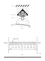
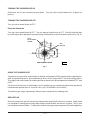
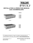
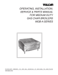
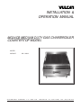
INSTALLATION &
OPERATION MANUAL
MG24CB MEDIUM DUTY GAS CHARBROILER
COUNTERTOP MODEL
MODEL
MG24CB
VULCAN-HART
FORM 31025 (3-97)
ML-114634
COMPANY,
P.O.
BOX
696,
LOUISVILLE,
KY
40201-0696,
TEL. (502) 7 7 8 - 2 7 9 1
IMPORTANT FOR YOUR SAFETY
THIS MANUAL HAS BEEN PREPARED FOR PERSONNEL QUALIFIED TO INSTALL GAS
EQUIPMENT, WHO SHOULD PERFORM THE INITIAL FIELD START-UP AND
ADJUSTMENTS OF THE EQUIPMENT COVERED BY THIS MANUAL.
POST IN A PROMINENT LOCATION THE INSTRUCTIONS TO BE FOLLOWED IN THE
EVENT THE SMELL OF GAS IS DETECTED. THIS INFORMATION CAN BE OBTAINED
FROM THE LOCAL GAS SUPPLIER.
IMPORTANT
IN THE EVENT A GAS ODOR IS DETECTED, SHUT
DOWN UNITS AT MAIN SHUTOFF VALVE AND
CONTACT THE LOCAL GAS COMPANY OR GAS
SUPPLIER FOR SERVICE.
FOR YOUR SAFETY
DO NOT STORE OR USE GASOLINE OR OTHER
FLAMMABLE VAPORS OR LIQUIDS IN THE
VICINITY OF THIS OR ANY OTHER APPLIANCE.
WARNING
IMPROPER INSTALLATION, ADJUSTMENT,
ALTERATION, SERVICE OR MAINTENANCE CAN
CAUSE PROPERTY DAMAGE, INJURY OR DEATH.
READ THE INSTALLATION, OPERATING AND
MAINTENANCE INSTRUCTIONS THOROUGHLY
BEFORE INSTALLING OR SERVICING THIS
EQUIPMENT.
IN THE EVENT OF A POWER FAILURE, DO NOT
ATTEMPT TO OPERATE THIS DEVICE.
© VULCAN-HART COMPANY, 1997
—2—
TABLE OF CONTENTS
GENERAL. . . . . . . . . . . . . . . . . . . . . . . . . . . . . . . . . . . . . . . . . . . . . . . . . . . . . . . . . . . . . . . . . . . . . . . 4
INSTALLATION . . . . . . . . . . . . . . . . . . . . . . . . . . . . . . . . . . . . . . . . . . . . . . . . . . . . . . . . . . . . . . . . . . 4
Unpacking . . . . . . . . . . . . . . . . . . . . . . . . . . . . . . . . . . . . . . . . . . . . . . . . . . . . . . . . . . . . . . . . . 4
Location . . . . . . . . . . . . . . . . . . . . . . . . . . . . . . . . . . . . . . . . . . . . . . . . . . . . . . . . . . . . . . . . . . 4
Installation Codes and Standards . . . . . . . . . . . . . . . . . . . . . . . . . . . . . . . . . . . . . . . . . . . . . . 5
Assembly . . . . . . . . . . . . . . . . . . . . . . . . . . . . . . . . . . . . . . . . . . . . . . . . . . . . . . . . . . . . . . . . . 5
Leveling . . . . . . . . . . . . . . . . . . . . . . . . . . . . . . . . . . . . . . . . . . . . . . . . . . . . . . . . . . . . . . . . . . 7
Gas Connections . . . . . . . . . . . . . . . . . . . . . . . . . . . . . . . . . . . . . . . . . . . . . . . . . . . . . . . . . . . 7
Testing the Gas Supply System . . . . . . . . . . . . . . . . . . . . . . . . . . . . . . . . . . . . . . . . . . . . . . . 7
Ventilation . . . . . . . . . . . . . . . . . . . . . . . . . . . . . . . . . . . . . . . . . . . . . . . . . . . . . . . . . . . . . . . . . 7
OPERATION . . . . . . . . . . . . . . . . . . . . . . . . . . . . . . . . . . . . . . . . . . . . . . . . . . . . . . . . . . . . . . . . . . . . 8
Controls . . . . . . . . . . . . . . . . . . . . . . . . . . . . . . . . . . . . . . . . . . . . . . . . . . . . . . . . . . . . . . . . . . 8
Before First Use . . . . . . . . . . . . . . . . . . . . . . . . . . . . . . . . . . . . . . . . . . . . . . . . . . . . . . . . . . . . 8
Lighting Instructions . . . . . . . . . . . . . . . . . . . . . . . . . . . . . . . . . . . . . . . . . . . . . . . . . . . . . . . . . 8
Turning the Charbroiler On . . . . . . . . . . . . . . . . . . . . . . . . . . . . . . . . . . . . . . . . . . . . . . . . . . . 9
Turning the Charbroiler Off . . . . . . . . . . . . . . . . . . . . . . . . . . . . . . . . . . . . . . . . . . . . . . . . . . . 9
Using the Charbroiler . . . . . . . . . . . . . . . . . . . . . . . . . . . . . . . . . . . . . . . . . . . . . . . . . . . . . . . . 9
Grease Pan. . . . . . . . . . . . . . . . . . . . . . . . . . . . . . . . . . . . . . . . . . . . . . . . . . . . . . . . . . . . . . . . 9
Cleaning . . . . . . . . . . . . . . . . . . . . . . . . . . . . . . . . . . . . . . . . . . . . . . . . . . . . . . . . . . . . . . . . . 10
MAINTENANCE . . . . . . . . . . . . . . . . . . . . . . . . . . . . . . . . . . . . . . . . . . . . . . . . . . . . . . . . . . . . . . . . . 11
Lubrication . . . . . . . . . . . . . . . . . . . . . . . . . . . . . . . . . . . . . . . . . . . . . . . . . . . . . . . . . . . . . . . 11
Service and Parts Information . . . . . . . . . . . . . . . . . . . . . . . . . . . . . . . . . . . . . . . . . . . . . . . . 11
—3—
Installation, Operation and Care of
MODEL MG24CB MEDIUM DUTY GAS CHARBROILER
COUNTERTOP MODEL
PLEASE KEEP THIS MANUAL FOR FUTURE USE
GENERAL
Vulcan charbroilers are produced with quality workmanship and material. Proper installation, usage
and maintenance of your charbroiler will result in many years of satisfactory performance.
It is suggested that you thoroughly read this entire manual and carefully follow all of the instructions
provided.
INSTALLATION
Before installing, verify that the type of gas supply (natural or propane) agrees with the specifications
on the rating plate located on the left-hand body side. If the supply and equipment requirements do
not agree, do not proceed with the installation. Contact your dealer or Vulcan Company immediately.
UNPACKING
This charbroiler was inspected before leaving the factory. The transportation company assumes full
responsibility for safe delivery upon acceptance of the shipment. Immediately after unpacking, check
for possible shipping damage. If the charbroiler is found to be damaged, save the packaging material
and contact the carrier within 15 days of delivery.
Remove the packing bag containing the adjustable legs. Carefully unpack the charbroiler and place
it in a work-accessible area as near to its final installed position as possible. Lift the grates and radiants
out of the carton.
LOCATION
The equipment area must be kept free and clear of combustible substances.
The charbroiler must be installed only in fire resistant locations.
—4—
When installed, minimum clearance from combustible construction must be 6" at the sides and 6" at
the rear; minimum clearance from non-combustible construction must be 0" at the sides and 4" at the
rear.
The installation location must allow adequate clearances for servicing and proper operation. A
minimum front clearance of 32" is required.
Do not obstruct the flow of combustion and ventilation air. Adequate clearance for air openings into
the combustion chamber must be provided. Make sure there is an adequate supply of air in the room
to replace air taken out by the ventilating system.
Do not permit fans to blow directly at the charbroiler. Wherever possible, avoid open windows next to
the charbroiler. Avoid wall-type fans which create air cross currents within the room.
INSTALLATION CODES AND STANDARDS
The charbroiler must be installed in accordance with:
In the United States of America:
1. State and local codes.
2. National Fuel Gas Code, ANSI-Z223.1 (latest edition). Copies may be obtained from The American
Gas Association, Inc., 1515 Wilson Blvd., Arlington, VA 22209.
In Canada:
1. Local codes.
2. CAN/CGA-B149.1 Installation for Natural Gas Burning Appliances and Equipment (latest edition).
3. CAN/CGA-B149.2 Installation for Propane Burning Appliances and Equipment (latest edition),
available from the Canadian Gas Association, 55 Scarsdale Road, Don Mills, Ontario, Canada
M3B2R3.
ASSEMBLY
The broiler is shipped as a complete unit and does not require field assembly except for the grates and
radiants.
Place the radiants in their position (Fig. 1). Make sure that radiants nestle properly on front and rear
supports. CAUTION: Do not drop radiants on supports.
Place the top grid grates in place with the grid bars sloping toward the front (Fig. 2), or with grid bars
horizontal (facing down). When grid grates are placed sloping toward the front, the grooves on top will
guide excess fat drippings into the grease trough.
—5—
Fig. 1
Fig. 2
—6—
LEVELING
Place a carpenter's level on top of the charbroiler. Level the charbroiler front to back and side to side
by turning the adjustment screw at the bottom of each leg.
GAS CONNECTIONS
Gas supply connections and any pipe joint compound must be resistant to the action of propane gases.
Location of the gas inlet is at the rear on the left side. Codes require that a gas shutoff valve must be
installed in the gas line ahead of the charbroiler.
Connect gas supply. Make sure the pipes are clean and free of obstructions.
Charbroilers are equipped with fixed burner orifices for use with natural or propane gas and no
adjustments are necessary.
Natural gas pressure regulators are preset for an outlet pressure of 3.7" W.C. (Water Column); propane
gas pressure regulators are preset for 10" W.C.
WARNING: PRIOR TO LIGHTING, CHECK ALL JOINTS IN THE GAS SUPPLY LINE FOR LEAKS.
USE SOAP AND WATER SOLUTION. DO NOT USE AN OPEN FLAME.
After piping has been checked for leaks, all piping receiving gas should be fully purged to remove air.
TESTING THE GAS SUPPLY SYSTEM
When gas supply pressure exceeds 1/2 psig (3.45 kPa), the charbroiler and its individual shutoff valve
must be disconnected from the gas supply piping system.
When gas supply pressure is 1/2 psig (3.45 kPa) or less, the charbroiler should be isolated from the gas
supply system by closing its individual manual shutoff valve.
VENTILATION
It is required that the exhaust fumes be ventilated to the outside of the building through a ventilation
system installed by qualified personnel.
Information on the construction and installation of ventilating hoods may be obtained from the standard
for "Vapor Removal from Cooking Equipment," NFPA No. 96 (latest edition), available from the
National Fire Protection Association, Batterymarch Park, Quincy, MA 02269.
—7—
OPERATION
WARNING: THE CHARBROILER AND ITS PARTS ARE HOT. USE CARE WHEN OPERATING,
CLEANING OR SERVICING THE CHARBROILER.
CONTROLS
Manual gas valves regulate gas flow to the burners to maintain set temperature.
BEFORE FIRST USE
Clean the protective metal oils from all surfaces of the charbroiler. Use a non-corrosive, grease
dissolving commercial cleaner, following manufacturer's directions. Rinse thoroughly and wipe dry
with a soft clean cloth. Clean all accessories. Rinse thoroughly and wipe dry.
LIGHTING INSTRUCTIONS
Lighting instructions are also inside the front panel. To access, remove four screws from the upper front
panel. Lift the front panel off until it clears the drip pan handle.
To install the front panel, slide out drip pan, replace front panel, and install four screws in panel.
Lighting the Pilot
If the pilot goes out, an automatic shutoff valve turns off the gas supply to the burners. To relight the
pilot, follow these procedures:
1. Turn the manual gas valves to the OFF position.
2. Turn the main shutoff valve to OFF.
3. Wait 5 minutes to allow gas which may have accumulated in the burner compartment to escape.
4. Turn the main shutoff valve ON.
5. Depress and hold in on the red button (Fig. 3) on the automatic shutoff valve while lighting the pilot
burner.
6. When gas at the pilot has been running for about 45 seconds, release the red button. If the pilot
does not remain lighted, repeat the above procedures, allowing more time before releasing the red
reset button.
All initial pilot lighting adjustments must be performed by a qualified installation or service person.
—8—
TURNING THE CHARBROILER ON
All burners are lit from constantly burning pilots. Turn gas valve control knobs to HI to ignite the
burners.
TURNING THE CHARBROILER OFF
Turn gas valve control knobs to OFF.
Extended Shutdown
Turn gas valve control knobs to OFF. Turn the manual shutoff valve to OFF. Shut off the pilot flame
by removing the pilot adjustment cap and turning the adjusting screw on the pilot shutoff valve (Fig. 3).
PILOT
ADJUSTMENT
SCREW
RED
BUTTON
PILOT SHUTOFF VALVE
PL-52719
Fig. 3
USING THE CHARBROILER
To preheat, turn gas valve control knobs to highest setting about 25-30 minutes before cooking time.
After this period of preheat, grid temperatures will be in the range of 600°F for best broiling results.
Then adjust the control knobs to a lower position to maintain the grid temperature between 575°F and
625°F.
Do not leave the burners on with knobs in the HI position for any extended period of time beyond the
recommended preheat time or "burn-off" time (see CLEANING in this manual).
To minimize gas usage, operate only those burners needed for the cooking load.
GREASE PAN
Grease in the grease pan will not get hot enough to be ignited by the burners; however, under some
use conditions, flaming particles may drop into the grease drawer and cause it to ignite. Only if your
use conditions warrant, add a 1/16" deep layer of water in the grease pan to prevent this from happening.
—9—
CLEANING
At least once a day, remove the grease pan, empty and wash it out in the same way you would any
cooking utensil.
"Burn off" the grease build-up on the grate daily or as dictated by use.
when handling grates or radiants to prevent burns.
Always use insulated gloves
CAUTION: Do not cover the top of the grid grates during a burn-off operation. Restricting the
air flow by covering the grid grates may cause them to warp.
The top grid grates and radiants are heavy. They may break if dropped or bumped.
To "burn off" the grates:
1. Place grates on broiler with grid bars horizontal, facing down.
2. Turn control knobs to HI for approximately 45 minutes.
3. Turn broiler OFF and allow it to cool for 20 minutes.
4. Clean top and bottom surfaces of grate with a wire brush to remove animal fats and carbonized
grease.
5. Clean channels on grates with a scraper.
6. Remove grates from broiler. Clean top surface of radiants with the wire brush. They may be
cleaned in place.
7. Once a week, after completing steps 1-6, remove the radiants. Using a brush, clean reflecting drip
shield (see Fig. 1) of any dust or debris.
Once a week, thoroughly clean the exposed surfaces of the broiler (sides, front and top grease trough)
with a damp cloth, then polish with a soft dry cloth. A detergent may be used for cleaning. To remove
discolorations, use a non-abrasive cleaner.
Burner air shutter openings must be kept clean.
Burner ports must be kept clean. To remove burners:
1. Remove the top grates.
2. Remove the radiants.
3. Remove the burners.
Brush burner ports with a wire brush or clean ports with a sharp pointed metal instrument to ensure
open ports.
Reverse above procedure for reassembly.
— 10 —
MAINTENANCE
WARNING: THE CHARBROILER AND ITS PARTS ARE HOT. USE CARE WHEN OPERATING,
CLEANING OR SERVICING THE CHARBROILER.
LUBRICATION
All valves must be checked and lubricated periodically by your local service agency.
SERVICE AND PARTS INFORMATION
To obtain service and parts information concerning this charbroiler, contact the Vulcan-Hart Service
Agency in your area (refer to listing supplied with the charbroiler), or Vulcan-Hart Company Service
Department at the address or phone number shown on the front cover of this manual.
FORM 31025 (3-97)
— 11 —
PRINTED IN U.S.A.
— 12 —