1
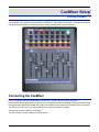
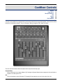
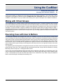
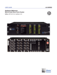
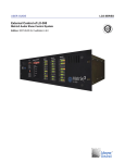
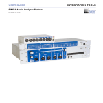
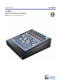
USER GUIDE
CueMixer
Matrix3 Audio Show Control System
Edition: 2007-09-19 for CueStation 4.6.0
LCS SERIES
Meyer Sound Laboratories Inc
2832 San Pablo Avenue
Berkeley, CA 94702
www.meyersound.com
T: +1 510 486.1166
F: +1 510 486.8356
© 2007
Meyer Sound Laboratories Inc.
© 2007 Meyer Sound. All rights reserved.
CueMixer User Guide
The contents of this manual are furnished for informational purposes only, are subject to change without notice, and
should not be construed as a commitment by Meyer Sound Laboratories Inc. Meyer Sound assumes no responsibility or liability for any errors or inaccuracies that may appear in this manual. Except as permitted by applicable
copyright law, no part of this publication may be reproduced, stored in a retrieval system, or transmitted, in any form
or by any means, electronic, mechanical, recording or otherwise, without prior written permission from Meyer Sound.
CueStation, CueConsole, LCS Series, Matrix3, Wild Tracks, VRAS and all alphanumeric product names are trademarks
of Meyer Sound. Meyer Sound and SpaceMap are registered trademarks of Meyer Sound Laboratories Inc. (Reg.
U.S. Pat. & TM. Off.). All third-party trademarks mentioned herein are the property of their respective trademark
holders.
Printed in the U.S.A.
Part Number: 05.164.075.01 rev.A
Table of Contents
CueMixer™ Setup
7
Connecting the CueMixer
CueMixer Controls
11
Modes
Page Select
Transport Buttons
EQ
Isolate
Mute
User Buttons
Programming CueMixer Functions
15
CueMixer Setup
User A Mode
Using the CueMixer
21
Mixing with Virtual Groups
Executing Cues with User A Buttons
CueMixer Details
23
Basic Operation
Reference
Service and Troubleshooting
29
Service
Calibration
5
6
CueMixer Setup
Connecting the CueMixer
7
The CueMixer™ is a physical control surface for the Matrix3™ audio show control system. The faders and buttons
provide a flexible interface for controlling audio processing and automation within the Matrix3.
Connecting the CueMixer
Power is suppled to the MS-CUEMIXER from an external +12VDC/2.5A power supply (included.)
Data is RS-422 and is connected to Port B of the LX-COS module in an MS-LX300 Matrix3 Primary Processor using
the supplied cable (DB-9 male to DB9 male). Only one CueMixer can be connected to a Matrix3 Primary Processor.
The default port is B, but you can change that to port A using an CueStation software.
The data rate for the CueMixer is 38.4K baud.
The data connector on the CueMixer is a DB-9 female.
7
Connecting the CueMixer
CueMixer
LX-COS module
Port B
RS-422
RS-422 Serial Cable
On the Matrix3 LX-COS module, Port A and Port B use the same connector pin-outs as the CueMixer, so the cable
connections are swapped from end to end. The cable needed to connect the LX-COS module to the CueMixer should
be wired as shown.
Use a two-shielded-pair stranded cable with low capacitance. Pins 4&5 are one pair, and 8&9 are the second pair.
(See the appendix for an application note on how to use two channels in an audio snake to run the CueMixer signal.)
8
Connecting the CueMixer
Table 1. CueMixer RS-422 Connection
Pin
Purpose
1
Shield
4
TxD+
5
TxD-
8
RxD+
9
RxD-
DIP Switch Settings
The dip-switches on the rear panel of the CueMixer are not used and their settings ignored by the electronics.
9
10
CueMixer Controls
Modes
Page Select
Transport Buttons
EQ
Isolate
Mute
User Buttons
12
12
13
14
14
14
14
Controls on the CueMixer are organized into sections with related functions grouped together. These sections match
functions in CueStation software. They are Transport, Editing, Navigation, EQ, Isolate and Mute.
The two most used buttons have been placed at the top left and the top right.
System Master
The top left button is the System Master [0]. Pressing the System Master button assigns the first two faders to
System Level and System Trim.
GO
The top right button is the GO button [7]. Pressing GO executes the next cue in the active Cue List.
11
Modes
Modes
Next to each button is an LED. On the top two rows of buttons, these LEDs are used to display the current mode
and page selection.
There are four modes on the CueMixer. These are System Master, Trims, Shift and EQ. For each mode, there is a
single button that will enter the mode - which is why there is a graphic box around both the button and the LED.
Note
The GO button is a special case; the LED is on all of the time to highlight the button.
Shift Mode
Pressing and releasing the Shift key allows you to select what the motorized faders display and control. The selections
available are: Inputs, Bus Levels, Outputs, Aux Outputs, and Virtual Groups using the button to the right of the desired
mode LED.
The Shift key [8] is a toggle. You press it once to toggle shift ON for the next key press. After the second key press,
shift is toggled off.
Important
You do not hold down the Shift key when pressing a second key. If the LED next to the Shift key is lit, then Shift
mode is active.
For example, to select Inputs:
1. Press and release the Shift key.
2. Press the button to the right of the “Inputs” LED (in the red box labeled STOP).
The faders will now reflect the state of the Input levels. Here is a list of the Shift selections and the button associated
with each:
Table 2. CueMixer Shift Examples
To Select:
With Shift Active Press:
Button No.
Inputs
STOP
2
Bus Masters
Skip <<
4
Output Masters
Skip >>
5
Aux Masters
Show
6
Virtual Groups
User B
11
Page Select
There can be hundreds of faders in a Matrix3 system. Since there are just eight faders on the CueMixer, Page Select
is used to choose which faders are displayed, in groups of eight at a time. The four keys [12, 13, 14, 15] labeled 1
2 3 4 are used to go instantly to the first four pages in a Matrix3 system.
You can also use the Shift key and the last two rows of buttons to go directly to any of 16 pages. With Shift toggled
ON, the Isolate buttons [16-23] are used to select pages 1 to 8 and the Mute buttons [24-31] are used to select
pages 9 to 16.
12
Transport Buttons
For example, to select faders 33 to 40, you need “page 5”. Press then release the Shift key (LED lights) then press
the Isolate button for fader number 5. There are blue numbers beneath each of the LEDs on the Isolate row of buttons.
These show pages 1 to 8. There are black numbers about the LEDs on the Mute row of buttons. These show pages
9 to 16.8
Table 3. Channel Pages
Page
Faders Show
1
1-8
2
9-16
3
17-24
4
25-32
5
33-40
6
41-48
7
49-56
8
57-64
9
65-72
10
73-80
11
81-88
12
89-96
13
97-104
14
105-112
15
113-120
16
121-128
Note
The CueMixer cannot display channels higher than 128.
Transport Buttons
The GO button is part of the Transport section of the CueMixer. The other transport functions are:
||< (Return to Start)
Moves Cue-on-Deck pointer to the top of the cue list.
<< (Skip Back)
Steps back one entry in the cue list.
>> (Skip Forward)
Steps forward one entry in the cue list.
These Skip controls, [4] & [5] allow you to move through the Cue List to select different cues while the Return to
Start [3] button takes you to the beginning of the list. The Show button [6] uses the Status display on the front of the
Matrix3 to show the next cue in the active cue list waiting to be sent. The display will show an “N” followed by the
Cue ID number. The STOP button [2] stops all automation in progress, including Wild Tracks playback and recording,
SpaceMap®, automated fades and waits, and pending cues and sub-cues.
The Trims button [1] changes the mode of the faders to show the Trim controls. In CueStation 4 you can program
trim settings, but by convention these are usually not programmed. This allows a live adjustment of a control type
13
EQ
that will allow automated levels to be offset. For example if you have a substitute musician and you need to adjust
the overall level without changing the programmed fades, you could use the trim control.
When the Trims LED is green selection of Inputs, Bus Lvls, Outputs, Aux Out, or VGroups, will set the faders to
control the Trims for these controls. If the Trims LED is dark, the faders will control the Levels for these controls
when selected.
EQ
The EQ button [9] lets you edit the EQ settings.
The CueMixer can display and edit up to 6 parametric EQ bands. If you have the Matrix3 configured for more than
6 bands of EQ, only the first 6 can be controlled and edited from the CueMixer. When editing EQ from the CueMixer
you use the faders to set parameters plus you can bypass individual bands and set delay times. Control of Dynamics
is not supported on the CueMixer.
Isolate
Most of the functions that are available in CueStation software are accessible from the CueMixer. The third row of
buttons [16-23] is used to Isolate a channel. These take individual channels out of the automation system for
manual control. There is a second function to this row that becomes active when you are editing EQ as these buttons
are used to select a channel to be edited.
Mute
The fourth row of buttons [24-31] is used to Mute channels. These mute the audio on individual channels and function
the same as the on-screen mute button in the CueStation software. There is a second function to this row that becomes
active when you are editing EQ. They are used to mute individual bands of the EQ. When the EQ button is pressed
the faders become controls for the EQ and the fourth row buttons allow you to bypass individual bands, bypass the
delay, or bypass all of the EQ bands.
User Buttons
The User A and User B buttons [10, 11] on the CueMixer can be programmed in CueStation to recall assigned cues.
Pressing a User A or B button at any time will fire the assigned cue. There is also a User A mode that is entered by
pressing (and releasing) Shift and then pressing the User A button. When you are in User A mode, the LED next to
the User A button is lit. In User A mode the bottom two rows of buttons can be mapped to fire any cue id. CueMixer
uses the page select buttons to switch between sets of these cue assignments (see the section on Navigation).
There are 16 pages in the system allowing you to map 256 cues to individual buttons. Duplicate assignments are
allowed.
14
Programming CueMixer Functions
CueMixer Setup
User A Mode
15
19
CueMixer Setup
By default the LX-300 connection to CueMixer is not enabled. An External Subcue is used to enable the connection
to a CueMixer.
When the LX-300 is first powered up, the CueMixer is not enabled. You must enable it by using the CueMixer RIF108 > Enable RIF command in the Frame Control window, or by programming an External Subcue.
From CueStation you can disable controls on the CueMixer. This can be used to restrict the control available to the
operator. The following external subcue commands control what CueMixer functions are enabled. By default, all
controls are enabled unless you use one of these commands to specifically disable them.
Important
After creating the subcues described in this section, you must then recall the subcue before the changes will go into
effect.
15
CueMixer Setup
Enable Console Modes
Enables these controls on the CueMixer. By default these are all of enabled until you use this command and select
"Disable" from the drop-down menus to disable the control on the CueMixer.
Enable EQ/Trim Modes
Enables these controls on the CueMixer. By default, these are all of enabled until you use this command and select
"Disable" from the drop-down menus to disable the control on the CueMixer.
16
CueMixer Setup
Enable Misc Console Modes
Enables these controls on the CueMixer. By default these are all of enabled until you use this command and select
"Disable" from the drop-down menus to disable the control on the CueMixer. The “Editing” controls are the ones
accessed by pressing Shift, and then using the Page 1, 2, 3, and 4 buttons.
Assign User A/B Cues
This external sets the Cue ID number to be fired when the User A or User B button is pressed. The default value
for all User buttons is cue 0 (zero). The hardware design of the CueMixer requires that all User buttons have an
assigned cue at all times. It is not possible to set the User buttons to Off. As a work-around to this limitation, the
CueMixer will not send Cue ID 0 (zero). In order to allow you to keep the User button from firing a cue, the default
setting is for the CueMixer not to send cue 0. If you need to assign Cue 0 to a User button, then you need to enable
the CueMixer to send cue 0. (please see Enable Cue 0 RIF).
17
CueMixer Setup
Note
Do not confuse User A button with User A mode. User A button fires a single cue when pressed. When you enter
User A mode (LED next to user A button is ON), then you have the use of the bottom two rows of buttons on the
CueMixer available to fire cues. (see “Set User A Mode” below.)
Enable Cue 0 CueMixer
Enables the CueMixer User A and User B buttons to send Cue id 0.
There is not a way to set the User button to Off. It must have a cue number assigned. In order to allow you to keep
the User button from firing a cue, you can program the CueMixer not to send cue id 0 and then make sure that the
User buttons are assigned to cue id 0.
Button Overlay
Button overlays provide a way of having any button execute a cue in addition to the standard function for that button.
With the current firmware and software release you can not disable the normal button function.
Set Mode
Sets the CueMixer mode.
Button Debounce
Button Debounce is used to keep a single button press from repeating the command. This can happen when the
switch contact “bounces”. Normally the hardware circuit would suppress this problem, but under some conditions it
can occur. During the Debounce interval the button is ignored.
18
User A Mode
Set Port on LX-300
Port B on the LX-COS module is the default port for connecting a CueMixer, but you can change the connection to
Port A. Please note that each LX-300 will only support one CueMixer.
User A Mode
This command is used to assign the Cues that are fired by last two rows of buttons on the CueMixer when you are
in User A mode.
Page
There are a total of 16 pages available.
Button
1 to 8 are the "Isolate" buttons left to right. 9 to 16 are the "Mute" buttons left to right.
Cue ID
This is the Cue ID number that is sent when the assigned button is pressed.
The User A Mode is entered by pressing and releasing the Shift button, and then immediately pressing the User A
button. The LED next to the User A button will light to show that you are in User A mode.
User A Mode: Select Page
When you are in the User A mode, the bottom two rows of buttons on the CueMixer are used to fire cues directly.
User A mode also uses the Page Select controls to give you 16 sets of 16 buttons. Selection is made by pressing
and releasing the Shift button, and then pressing one of the Isolate or Mute buttons. You can also change User A
Mode pages automatically with a subcue.
The same cue can be assigned to more than one button. When User A mode is on, the User A and User B buttons
are still active (as long as they have not been disabled).
User A Mode: Print Button Assignments
This command prints to the Log a list of the cues that have been assigned to User A Mode buttons.
19
20
Using the CueMixer
Mixing with Virtual Groups
Executing Cues with User A Buttons
21
21
Connect the CueMixer to a Matrix3 LX-COS module (Port B is the default connection), turn on the power, send a
configuration to the Matrix3, and then send the CueMixer RIF-108 > Enable RIF command. You can connect one
CueMixer to each Matrix3. To get you started, the following are a couple of examples from CueMixer installations.
Mixing with Virtual Groups
The sound designer for a theatre musical review was faced with three acts, 24 musical numbers and 26 wireless
mics. Since members of the cast could be lead in one scene and secondary or chorus in another, cues were created
for each segment that assigned all inputs to virtual groups depending on whether the mic was on the principal, a
secondary, or a chorus member. Using the CueMixer to mix Vgroups means that the principal is always on fader 1,
secondary characters are next, and the chorus is at the end. The mix within a group is available on the input faders
programmable from scene to scene and the trims provide a way of making a global level adjustment outside of the
automation system.
Executing Cues with User A Buttons
In a theme park attraction walk through action show, the CueMixer is used in the control booth to monitor three
actors on wireless mics and five simultaneous performance zones. The attraction is designed to operate continuously
with guests moving in groups between the performance zones. The first zone is where guests are gathered in a line.
A background music track played by Wild Tracksas an accompaniment to the static displays in the corridor where
the line forms. There is an actor that first appears as the group is formed in the second performance zone. This
actor will stay with the group as they move through the next three zones. As a new group is formed, a new actor
joins the group.
The attraction is paced so that there is enough time for an actor to finish in zone four and meet up with the next new
group forming in zone two. This means that that are always three actors in play while the attraction is running.
Monitoring uses Aux output no. 1 feeding the booth monitor.
A set of cues using the Set Parameter Subcue function were created to set Aux Send 1 of each input to unity. The
User A buttons on the CueMixer were mapped to fire these cues. Now a single button press on the CueMixer clears
all Aux 1 sends and then sets the Aux send of the channel to be monitored to unity. Allow overlap is enabled for
these cues so that they do not disrupt the executing cues.
21
22
CueMixer Details
Basic Operation
Reference
23
24
Basic Operation
When the CueMixer is first powered up it starts with System Master as the current mode. The System Master LED
in the upper left corner is lit and the first two faders are the Automated System Level and the Manual System Level.
The user can press and release the SHIFT key to enter the SHIFT-mode. When in the SHIFT-mode, the LED next
to the SHIFT button will be lit. Pressing another key will bring up a new mode (Inputs, Bus Lvls, Outputs, Aux Out,
User A, or VGroups).
The TRIMS button is used to select trims mode for Input, Bus Levels, Output, and Aux. When you press the TRIMS
button you will enter the Trims mode last selected. The default is Input Trims. The TRIMS LED will light and the Inputs
mode LED will also light. You use Shift and then mode to select a different Trims mode. As long as the TRIMS LED
is lit, you are adjusting the TRIMS.
To leave the TRIMS mode, just press TRIMS a second time. The next time you enter TRIMS, you will be in the last
selected TRIMS mode. For Example if you are adjusting the Output Trims and you toggle out of TRIMS and select
Input mode - when you again press TRIMS, you will return to the Output Trims mode (since this was the last Trims
mode you had selected).
The EQ button works like the TRIMS button. When you select EQ, you then are in EQ mode and can select Input,
Output, and Aux modes. When you press EQ a second time, you leave EQ and return to whatever mode you were
in before pressing EQ.
Note
If you try to select a mode that doesn't have trims, the CueMixer will not allow you to make the selection. The same
is true for EQ (when in EQ mode you will only be able to select other modes that support EQ).
When you select EQ or Trims the current mode will be saved. The last selected mode for EQ or Trims will be recalled.
If you have not used EQ or Trims, the default selection will be Inputs. EQ and Trims are mutually exclusive. Pressing
EQ while in Trims or Trims while in EQ will switch modes. You can flip back and forth between EQ and Trims, and
the CueMixer will always revert to the last selected mode for each. When you enter EQ or Trims, the CueMixer notes
the mode you were in, and saves it as the "current" mode. If both EQ and Trims are toggled off, then the CueMixer
will go back to current mode.
If while the EQ or Trims mode is in effect, the user presses System Master, the CueMixer will take itself out of EQ
or Trims (saving the setting). When Trims or EQ is next pressed, the mode last selected will be used.
Changing the Page
There are four buttons in the second row that allow you to instantly select pages 1 through 4. You can also select
any of the 16 pages in a fully configured 128 input system using the Shift key and the bottom two rows of buttons.
When you press the Shift key, the Isolate and Mute LEDs go out, and the 16 LEDs from Isolate 1 down to Mute 8
become page 1 thru page 16. The page that is currently selected will have that buttons’ LED light up.
When you select a new page the shift LED goes out, the new page LED stays on for 1 second. The Isolate and Mute
LEDs then revert to displaying their named functions.
23
Reference
Reference
The following section provides details for each, LED, button and feature found on the CueMixer.
First Row of LEDs
The mode LEDs are used to indicate the active mode. When using the CueMixer along with a computer you will see
the active mode as the top window on the computer monitor (IF you have Enabled “Window Follow” for the CueMixer).
The mode indicates what the faders are controlling.
System
System Level (Auto) and Manual System Level (Manual) faders active.
Trims
The Trims LED is used to show that Trims has been toggled ON. Input Trims trims and Output trims are displayed
by using both the Trims LED and the respective Input /Output LEDs. If you toggle Trims ON, then try to select
a mode that does not have trims. The CueMixer will not change to that mode until you toggle Trims OFF.
Inputs
Console Input faders active.
Bus Levels
Bus Level faders active.
Outputs
Output Master faders active.
Aux Out
Aux Output Master faders active.
GO
The eighth LED is on all of the time. It is used as a visual target for the GO button.
First Row of Buttons
System Master
This button gives instant access to the Automated System Level (fader 1) and the Manual System Level (fader
2).
Important
Aux Outputs are PRE-System Master (i.e. pulling the Master faders down will not silence the Aux Outputs).
Trims
The Trims button is a toggle, selecting between Inputs (trim), Bus Levels (trim), or Outputs (trim). This is displayed
by having both the Trims LED on and the selected mode LED on. If you toggle Trims ON, then try to select a
mode that does not have trims, the CueMixer will not change mode.
STOP
Stops scheduler, trajectory, Wild Tracks playback, and pending cues and subcues.
||<
Return to Beginning. This is the return to the top of the Cue List function for the transport window.
<< Skip
The same as stepping to a lower numbered cue in the Cue List in the transport window.
>> Skip
The same as stepping to a higher numbered cue in the Cue List in the transport window.
24
Reference
Show
This causes the Status display on the front of the LX-300 to show the next cue in the active Cue List. The status
display is in the form “Nxxx” When N shows that it is the “Next” cue and xxx is the cue ID number for the next
cue.
GO
This is the same as the GO button in the transport window. Pressing it is the same as clicking on the GO button
on the computer monitor. Note that the LED above this button is lit all of the time.
Second Row of LEDs
Shift
Lights to show that Shift is toggled on.
EQ
The EQ LED is used to show that EQ mode is active. It is used along with the Inputs, Aux Out, and Outputs
LEDs to show which EQ section you are controlling. If you try to select a mode that does not have EQ, the
CueMixer will not change to that mode.
User A
Lights when the CueMixer is in User A mode.
VGroups
Lights to show faders are VGroup controls.
Page Select 1
Page 1 selected (faders 1 to 8).
Page Select 2
Page 2 selected (faders 9 to 16).
Page Select 3
Page 3 selected (faders 17 to 24).
Page Select 4
Page 4 selected (faders 25 to 32).
Second Row of Buttons
Shift
The Shift key is a toggling function and is used to access shifted functions. Pressing the Shift key and then releasing it toggles on the shift function for the next button press. After the second button press, shift is released.
DO NOT HOLD DOWN ON SHIFT WHEN PRESSING THE SECOND KEY.
The modes are: System, Inputs, Bus Levels, Aux Outputs, Output masters*, Virtual Groups, Input EQ*, Aux Out
EQ*, Output EQ*, User, Input trims, Wild Tracks trims, and Output trims*.
EQ
Selects EQ for the modes with EQ (Inputs, Aux Outputs, Outputs).
User A
Fires the User A cue. (Use the Shift button to selects User A mode). The User A button by default issues a Cue
Zero. In User A mode (shift selected), the default value for all cues is zero. The CueMixer will not send Cue
Zero unless that function has been enabled (see Enable Cue 0 CueMixer in Programming CueMixer Functions
(p. 15)).
User B
Fires User B cue.
The four buttons next to the User B buttons have “shifted” functions. When the Shift button is toggled and one
of these buttons is pressed, they function as labeled in red above the button. They are used for programming
in conjunction with the Cue Lists and Cue Library windows in CueStation.
Page Select 1
(Unshifted) Hot button select of page 1.
25
Reference
(Shifted) [c.NEW]: Cue Lists window- Makes a new cue entry with the default name, captures all, and then puts
it in a cue list. A Cue List must be selected in the Cue Lists window. This is the same as pressing F4 while in
the Cue Lists window with a Cue List selected.
Page Select 2
(Unshifted) Hot button select of page 2.
(Shifted) [c.ALL]: Cue Library window- is the Capture ALL command. A Cue must be selected in the Cue Library
window. The Capture All prompt opens (Capture All: Cancel, More…, Capture).
Page Select 3
(Unshifted) Hot button select of page 3.
(Shifted) [c.DFT]: Cue Lists window- Capture Difference & Follow through command. A Cue List must be selected
with a Cue highlighted. The Capture Differences and Follow Through prompt will appear.
Page Select 4
(Unshifted) Hot button select of page.
(Shifted) [c.DIF]: Cue Library window- is the Capture Differences command. A Cue must be selected in the Cue
Library window. The Capture Differences prompt will open.
Note
To use the CueMixer in programming a Matrix3 system you need to be familiar with CueStation software. Please
see the CueStation manual for details on the functions of these buttons.
When EQ is Active
When EQ is active, many controls change function. For instance, the yellow Isolate LEDs switch to display the EQ
channel. The mode LEDs change to reflect either input, output, or aux modes (top row, LEDs 2, 6, or 5). The Isolate
buttons become Ch. Sel. and are used to select the channel for EQ. The Isolate LEDs are used to show the selected
channel. The faders now function as the blue label at the bottom calls out. Take special note of fader no. 8 as it is
used to select the EQ bands assigned to the first six faders. With fader 8 at minimum the first two bands are selected.
Moving the fader to 50% selects bands 3 & 4. Setting the fader at maximum selects bands 5&6 (5 only for the input
EQ). There is a dead zone between positions.
The Mute buttons are used to bypass individual bands or the entire EQ section. Please see details under the Mute
button entry.
Table 4. EQ Fader Functions
Fader
Fader Function
Mute Function
1
Band 1 Gain
Bypass Band 1
2
Band 1 Frequency
Bypass Band 2
3
Band 1 Q
Bypass Band 3
4
Band 2 Gain
Bypass Band 4
5
Band 2 Frequency
Bypass Band 5
6
Band 2 Q
Bypass Band 6
7
Delay Time
-
8
EQ Band Select
Bypass All
The bypass ALL function toggles between current band settings (bypassed or not) and all bands bypassed. It does
NOT bypass the Delay. Note when you toggle out of ALL Bypass the status of the individual Bands are restored.
(e.g. Band 1 is bypassed and all others are engaged. Pressing Bypass ALL bypasses everything. Pressing Bypass
ALL a second time to toggle out results in Band 1 still being bypassed but all others engaged again.)
26
Reference
Third Row of LEDs
The third row of LEDs and the third row of buttons are used to show a channel has been Isolated from automation.
When EQ is active, these LEDs are used to display the channel being edited (the blue numbers beneath each LED).
When the Shift key has been toggled on, these LEDs are used with the bottom row of LEDs to show which of 16
pages have been selected.
Third Row of Buttons
Isolate Channel
The third row of buttons, is used to remove channels from automation during a show.
When EQ is active, these buttons are used to select the channel to be edited. When the Shift key has been
toggled, these buttons select the current page for page 1 to 8.
Fourth Row of LEDs
The fourth row of LEDs are used for Mute. LED ON means the channel is muted. When active, these LEDs display
EQ bypass. LED ON means EQ Band is bypassed.
Fourth Row of Buttons
Mute Channel
These buttons mute the selected channel. When the Shift key has been toggled, these buttons select the current
page for page 9 to 16.
27
28
Service and Troubleshooting
Service
Calibration
29
29
When power is first applied to the CueMixer, it runs through a self-test. The LEDs turn on one row at a time starting
with the bottom row and working to the top. All fader motors are cycled and then moved to the 1/3rd travel position.
There are no fuses or user serviceable parts inside. If you are having trouble please contact LCS Series Technical
Support. Moving a fader or pressing a button on the CueMixer, will cause the appropriate Receive LED on the front
of the LX-300 Communication Synchronization display to light while the control is being moved. If you do not see a
response on the LX-300, check your cable.
Table 5. Troubleshooting
Problem
Solution
CueMixer fader moves the on screen fader, but jumps The LX-300 connected to the CueMixer does not have
back when released. CueMixer buttons do not change the connected port enabled for CueMixer. Use either
functions.
Frame Control, or an External Subcue to enable the
CueMixer.
Fader makes a 'tapping' sound at the bottom of travel The fader calibration needs adjustment. This requires a
when the screen fader is set to (all the way down).
qualified electronic service technician. Please contact
Meyer Sound for instructions.
GO button 'double-triggers'.
Use the 'Set Button Debounce Period' external to set the
Debounce interval.
Service
There are no user serviceable parts inside a CueMixer. There are no lubricants required for the faders. Service
should be done only by qualified service technicians.
Calibration
Warning
The following information is provided for qualified service technicians only. It is possible to damage the unit and to
void the warranty if standard electronic service procedures are not followed. Determination of the warranty status
of any unit will be done exclusively by Meyer Sound Laboratories.
Disconnect the power supply and open the unit. There are two hex standoffs, one on each side of the DB-9 connector
that must be removed. Use a 3/16th Hex driver. There are six hex socket flat head screws that attach the top plate.
Use a 2mm hex key to remove these. Be careful removing the top as it is possible to short out the voltage regulator
when removing the top plate. All circuit boards attach to the top plate so you do not have to remove fader knobs.
Caution
There is a metal EMI shield around the DB-9 connector. On some units this is not glued and will come off. It is possible
on reassembly to install this upside down preventing connection to the serial connector.
29
Calibration
There are four circuit boards in the unit. There is a board that has all of the push-button switches and LEDs mounted
on it. Mounted above this is a circuit board with the microprocessor and one of the trim pots you will need to adjust.
The other two boards are for the faders. Each has four faders and the associated circuitry for those faders.
Verification and Minor Adjustment
Adjustment is done to align the fader position and to set the servo gain. There is an interaction between these two
adjustments and you will have to make small adjustments to each control in turn in order to converge the settings.
1. Start with the front panel positioned so that you can access the trimmers and the front panel. Placing the panel
on the side so that the faders are horizontal works well. Faders must be able to travel freely.
2. With the serial cable disconnected, connect the power supply and energize the unit. The power on self test
should position all 8 faders at approximately –25 on the front panel.
3. Each group of four faders are mounted to a circuit board. There is one trim adjustment on this board that sets
the fader position. This is labeled “T1” and is the only trim pot on the fader board. If the board is working correctly,
the trim setting required will be in the middle of the range of adjustment. It is not possible to adjust individual
faders within the set of four.
4. Once the fader position has been adjusted, connect the CueMixer to a LX-COM module and enable the CueMixer in CueStation software. The controls should reflect the status of the Matrix3 system at this point.
5. On the CueMixer, select INPUTS and Page 1.
6. In CueStation, set Inputs 1 to 8 at –infinity (all the way off.)
7. Verify that the faders do not “click” when at the bottom of their travel on the CueMixer. You may have to adjust
“T1” on the fader board slightly to avoid have the fader bottom-out on the mechanical end stop. Note that when
at rest, the fader motors are still energized once a second so if you listen closely you will hear a slight buzzing
noise. What you don’t want to hear is the fader hitting the end-stop.
8. In CueStation set Inputs 1 to 8 to +10.
9. The circuit board with the DB-9 connector is the CPU board. It has a single trim adjustment also labeled “T1”.
This sets the servo gain for all 8 faders.
Verify that the faders do not “click” when at the top of their travel on the CueMixer. If they do, then you will have to
adjust “T1” on the CPU board.
10. In CueStation, set Inputs 1 to 8 to +0 (Unity.)
11. Verify that all the faders align with the 0 label on the front panel. The faders may not be perfectly in line, but
they should be within 3mm.
Fader Creep
Caution
If the CPU T1 is not adjusted correctly, the faders will “creep” when touched and released without moving the fader.
To test for this, lightly touch the side of the fader knob. You need enough pressure so that the fader does detect
your touch, but do not move the fader. When you release your touch the fader should not move. Repeated touching
should not show changes in CueStation for the fader level. It is normal for the first touch to show a change of up to
+/- 1.5.
If the faders creep up in value, adjust CPU T1 clock-wise.
If the faders creep down in value, adjust the CPU T1 counter-clock-wise.
Note that adjustments to the CPU T1 and the Fader Board T1 interact. You will have to go between the two states
successively to reach the final adjustments.
30
Calibration
Trim Adjustment Locations
DB-9
CPU
Board
T1
Fader
Board
Fader
Board
T1
T1
Resetting Trim Adjustments
If minor adjustments do not align the faders, or if the trim adjustments are too far out of range, you can start over
using the following steps:
1. In CueStation, set Inputs 1 to 8 to –25.0
2. Use Fader Board T1 to adjust each set of four faders to align with –25 on the front panel.
3. In CueStation, set Inputs 1 to 8 to 0.0
4. Use CPU T1 to adjust all eight faders to align with +0 on the front panel.
5. In CueStation, set Inputs 1 to 8 to +0 (Unity.)
6. Repeat steps 1 to 5 several times to converge adjustments. Each cycle should require a smaller adjustment.
(Note that there is a large null area in the adjustment of CPU T1.)
7. In CueStation, set Inputs 1 to 8 to –Infinity. If necessary make a small adjustment to Fader Board T1 keep any
fader from hitting the end stop and clicking.
8. In CueStation, Set Inputs 1 to 8 to +10.0. If necessary make a small adjustment to CPU T1 to keep any fader
from hitting the end stop and clicking.
9. Test the faders for creep. If the faders creep up in value, adjust CPU T1 clock-wise. If the faders creep down
in value, adjust the CPU T1 counter-clock-wise.
10. In CueStation, set Inputs 1 to 8 to –25.0 and verify that the faders are all aligned within 3mm. If not, go to step
1 and start over.
31
32