1
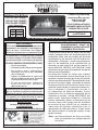
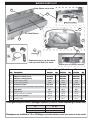
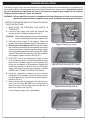
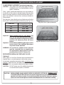
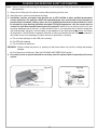
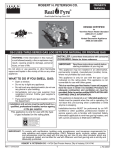
OWNER’S
MANUAL
DESIGN CERTIFIED
Burner Systems:
to
Vented Decorative Appliance
ANSI Z21.60b-2004
CSA 2.26b-2004
G21-GL-18C-12(M)(P)
G21-GL-24C-12(M)(P)
G21-GL-30C-12(M)(P)
FOR INSTALLATION IN
SOLID-FUEL BURNING
FIREPLACES*
FOR USE WITH
FYRE GLASS / FYRE GEMS
18"
7.5 lbs
24"
10.0 lbs
30"
15.0 lbs
FOR INDOOR OR
OUTDOOR USE
G21-GL VENTED BURNER SYSTEMS
IMPORTANT: READ THESE INSTRUCTIONS
CAREFULLY BEFORE STARTING
INSTALLATION OF THE LOG SET
WARNING
If the information in this manual is not
followed exactly, a fire or explosion
may result, causing property damage,
personal injury, or loss of life.
The Real-Fyre gas log set is to be installed only in a
solid-fuel burning fireplace with a working flue and
constructed of noncombustible material.The installation,
including provisions for combustion and ventilation air
must conform with the National Fuel Gas Code, ANSI
Z223.1/NFPA 54, or the CSA B149.1, Natural Gas
and Propane Installation Code, and applicable local
building codes.
A damper clamp is included to maintain the minimum
permanent vent opening and to prevent full closure of
the damper blade. The chimney damper MUST be
fully opened when burning the log set.The log set is
designed to burn with yellow flames; thus adequate
ventilation is absolutely necessary.
To comply with certification, listings, and building
code acceptances, and for safe operation and proper
performance of this log set, use ONLY Peterson
parts and accessories. Use of other controls, parts,
and accessories that are not designed for use with
Real-Fyre gas log sets is prohibited and will void all
warranties, certifications, listings, and building code
approvals, and may cause property damage, personal
injury, or loss of life.
*Note: Solid-fuels shall not be burned in a fireplace
where a decorative appliance is installed.
Do not store or use gasoline or other
flammable vapors and liquids in the
vicinity of this or any other appliance.
WHAT TO DO IF YOU SMELL GAS:
• Open a window.
• Do not try to light any appliance.
• Do not touch any electrical switch; do
not use any phone in the building.
• Immediately call the gas supplier
from a neighbor’s phone. Follow gas
supplier’s instructions.
• If you cannot reach the gas supplier,
call the fire department.
Installation and service must be performed
by a qualified professional installer,
service agency, or the gas supplier.
This appliance is only for use with the type
of gas indicated on the rating plate.
INSTALLER:
Leave this manual with the appliance.
CONSUMER:
Retain this manual for future reference.
10-104
Robert H. Peterson Co. • 14724 East Proctor Avenue • City of Industry, CA 91746
REV 2- 1105051552
1
L-A2-312
MANUEL DU
PROPRIÉTAIRE
CONCEPTION CERTIFIÉE
Systèmes De Brûleur:
à
Vented Decorative Appliance
ANSI Z21.60b-2004
CSA 2.26b-2004
G21-GL-18C-12(M)(P)
G21-GL-24C-12(M)(P)
G21-GL-30C-12(M)(P)
POUR L’INSTALLATION EN
CHEMINÉES BRÛLANTES DE
COMBUSTIBLE SOLIDE*
POUR L'USAGE AVEC
FYRE GLASS / FYRE GEMS
18"
7.5 lbs
24"
10.0 lbs
30"
15.0 lbs
POUR L'USAGE D'INTÉRIEUR
OU EXTÉRIEUR
G21-GL SYSTÈMES EXHALÉS DE BRÛLEUR
IMPORTANT: L I S E Z C E S I N S T RU C T I O N S
SOIGNEUSEMENT AVANT DE
COMMENCER L'INSTALLATION DE
L'ENSEMBLE DE NOTATION.
L'ensemble de notation de gaz d'Real-Fyre doit être
installée seulement dans une cheminée brûlante de
combustible solide avec une conduite de cheminée
fonctionnante et être construit avec du matériel noncombustible. L'installation, y compris des dispositions
pour l'air de combustion et de ventilation doit se
conformer au code national de gaz de carburant, la
norme ANSI Z223.1/NFPA 54, ou le CSA B149.1, code
d'installation de gaz naturel et de propane, et codes du
bâtiment locaux applicables.
Une bride plus humide est incluse pour maintenir
l’ouverture permanente minimum de passage et pour
empêcher la pleine fermeture de la lame plus humide.
L’amortisseur de cheminée DOIT être entièrement ouvert
en brûlant la notation réglée. L’ensemble de notation
est conçu pour brûler avec les flammes jaunes; ainsi à
ventilation proportionnée est absolument nécessaire.
Pour se conformer à la certification, les listes, et
les acceptations de codes du bâtiment, et pour
l'exploitation sûre et l'exécution appropriée de cet
ensemble de notation, utilisent SEULEMENT des
pièces et des accessoires d'Peterson. L'utilisation
d'autres commandes, pièces, et accessoires qui ne
sont pas conçus pour l'usage avec des ensembles
de notation de gaz d'Real-Fyre est interdite et
videra toutes les garanties, certifications, listes, et
approbations de codes du bâtiment, et peut causer
des dégats matériels, le dommage corporel, ou des
pertes humaines.
*Note: des Plein-carburants ne seront pas brûlés
dans une cheminée où un appareil décoratif
est installé.
AVERTISSEMENT
Si l’information en ce manuel n’est pas suivie
exactement, une incendie ou une explosion
peut résulter, entraînant des dégats
matériels, des blessures, ou la perte de la vie.
Ne stockez pas ou n’employez pas l’essence
ou d’autres vapeurs et liquides inflammables
à proximité de ceci ou d’aucun autre appareil.
CE QUI À FAIRE SI VOUS SENTEZ LE GAZ:
• Ouvrez une fenêtre.
• N’essayez pas de n’allumer aucun appareil.
• Ne touchez aucun commutateur
électrique; n’utilisez aucun téléphone
dans le bâtiment.
• Appelez immédiatement le fournisseur
de gaz du téléphone du voisin. Suivez les
instructions du fournisseur de gaz.
• Si vous ne pouvez pas atteindre le
fo u r n i s s e u r d e g a z , a p p e l e z l e
département de feu.
L’installation et le service doivent être assurés
par un installateur qualifié et professionnel,
l’agence de service, ou le fournisseur de gaz.
Cet appareil sert seulement avec le type de
gaz indiqué de la plaque de contrôle.
INSTALLATEUR :
Laissez ce manuel avec l'appareil.
CONSOMMATEUR:
Maintenez ce manuel pour la future référence.
10-104
Robert H. Peterson Co. • 14724 East Proctor Avenue • City of Industry, CA 91746
REV 2- 1105051552
2
L-A2-312
TABLE OF CONTENTS
5
IMPORTANT PRE-INSTALLATION AND FIREPLACE SAFETY INFORMATION
6
SPECIFICATIONS
6
DAMPER CLAMP INSTRUCTIONS
7
BURNER PARTS LIST
8
BURNER INSTALLATION
9
REMOTE SYSTEM (if equipped)
9
CONTROL SETTINGS
10
DECORATIVE MEDIA PLACEMENT
10
GLASS/GEMS PLACEMENT (purchased separately)
10
DECORATIVE MEDIA ON FIREPLACE FLOOR (Optional)
11
CLEANING AND SERVICING SAFETY INFORMATION
12
CLEANING AND SERVICING
12
TO CLEAN THE BURNER SYSTEM
12
CLEANING AND SERVICING THE ODS PILOT
13
OPERATING THE BURNER SYSTEM
13
CHECKING THE ODS PILOT FLAME APPEARANCE
14
LIGHTING INSTRUCTIONS - SERIES 12 VALVE
15
TROUBLESHOOTING
18
WARRANTY
REV 2- 1105051552
3
L-A2-312
L'INFORMATION DE SÛRETÉ IMPORTANTE DE PRÉINSTALLATION ET DE CHEMINÉE
ATTENTION:
L'installation et la réparation doivent être faites par un NFI certifié ou tout autre installateur
professionnel qualifié.
Installateur:
Lisez soigneusement ces instructions avant d'installer ce système de brûleur à gaz. Soyez sûr que vous
comprenez tous les mesures de sécurité et avertissements contenus en ce manuel.
A. Cet appareil est conçu comme appareil occupé. Les adultes doivent être présent quand cet appareil à gaz fonctionne.
Ne laissez pas ce burning d'unité si sans surveillance ou tandis que n'importe qui dort.
B. Cet appareil sert seulement avec le type de gaz indiqué de la plaque de contrôle. Cet appareil n'est pas CONVERTIBLE
de CHAMP pour l'usage avec d'autres gaz.
C. FAITES ATTENTION: Sinon installé, entretenu, et utilisé correctement par ces instructions, ce produit peut
causer le dommage corporel, les dégats matériels, ou les pertes humaines sérieux.
D. AVERTISSEMENT: Avant l'installation dans une cheminée plein-carburant-brûlante, la conduite de cheminée,
l'amortisseur, et le foyer de cheminée doivent ÊTRE COMPLÈTEMENT NETTOYÉS de la suie, de la créosote, des
cendres, et de la peinture lâche, et doivent être inspectés par un décapant qualifié de cheminée. Quelques cheminées
plus anciennes peuvent ont besoin de réparation avant d'installer cet appareil.
E. VÉRIFIEZ LE TYPE de GAZ (normal ou propane) : La fourniture de gaz doit être identique qu'indiquée de votre
plaque de contrôle de système de brûleur. Si la fourniture de gaz est différente, N'INSTALLEZ PAS. Contactez votre
revendeur pour l'aide immédiate.
F.
Gardez le domaine du clair réglé de notation de gaz et libérez des matériaux combustibles, l'essence, et d'autres
vapeurs et liquides inflammables.
G. LA PRESSION DE GAZ INSUFFISANTE GARDERA LE PILOTE DU FONCTIONNEMENT CORRECTEMENT (SI
ÉQUIPÉ). N'EMPLOYEZ PAS SI LA PRESSION DE GAZ EST INFÉRIEURE À LA CONDITION MINIMUM.
H. L'admission minimum gaz-fournissent la pression aux fins de l'ajustement d'entrée est 5" ; colonne d'eau (w.c.) sur le
gaz naturel et le 11" ; w.c. sur le gaz de propane. La pression de gaz insuffisante affectera l'opération appropriée du
pilote (si équipé). N'installez pas cet appareil à gaz si la pression minimum n'est pas disponible. L'admission maximum
gaz-fournissent la pression est 10.5" ; w.c. sur le gaz naturel et le 13" ; w.c. sur le gaz de propane. La source de
propane doit être réglée. (Ne reliez pas cet appareil directement à un réservoir de gaz non réglé de propane - ceci
peut causer une explosion.)
I.
Le système sifflant de gaz doit être classé pour fournir la pression d'admission minimum au débit maximum (BTU/hr).
La perte de pression anormale se produira si la pipe est trop petite, ou la course est trop longue. La pipe de fourniture
de gaz doit être 1/2" ; diamètre intérieur minimum. Si la ligne de gaz est plus longue que 20' ; une ligne de plus grand
diamètre peut être nécessaire.
J. Les estimations d'entrée montrées en Btu par heure sont pour des altitudes jusqu'à 2.000 pi. Pour des altitudes audessus de 2.000 pi, référez-vous au code national de gaz de carburant ou entrez en contact avec le fabricant avant
d'installer ce produit.
K. Cet appareil à gaz et son clapet à gaz principal doivent être disconnected du gaz-fournissent le système sifflant pendant
tout vérificateur de pression de ce système aux pressions d'essai au-dessus de 1/2 psig.
L. Cet appareil à gaz doit être isolé dans gaz-fournissent le système sifflant en fermant le robinet d'isolement d'équipement
relié au gaz-fournissent la ligne pendant tout vérificateur de pression du gaz-fournissent le système sifflant aux pressions
d'essai égales à ou moins d'à 1/2 psig.
M. N'employez pas cet appareil si n'importe quelle partie a été sous-marine. Appelez immédiatement un technicien qualifié
de service pour inspecter l'appareil et pour remplacer n'importe quelle partie du système de contrôle et de n'importe
quelle commande de gaz qui a été sous-marine.
N. Una pantalla de la chimenea debe ser en el lugar cuando el sistema está quemando. Las provisiones para el aire de
combustión adecuado deben ser mantenidas. A menos que otras provisiones para el aire de combustión se proporcionen,
la pantalla tendrá una abertura para la introducción de aire de combustión. El aire de combustión es adecuado cuando
todas las llamas se encrespan en la chimenea y lejos de la pantalla. Cuando se utiliza un recinto de cristal de la
chimenea (puerta), deje las puertas completamente abiertas cuando el sistema es en funcionamiento.
O. Cet appareil peut être installé dans un marché des accessoires, maison (mobile) de manière permanente située et
manufacturée, où non interdit par des codes locaux. L'installation des appareils a conçu pour la maison manufacturée
(États-Unis seulement) ou installation de caravane résidentielle doit se conformer au CAN/CSA standard Z240 MH,
logement mobile, au Canada, ou à la construction et au standard de sécurité à la maison manufacturés, intitulent 24
CFR, la partie 3280, aux Etats-Unis, ou quand une telle norme ne s'applique pas, à ANSI/NCSBCS A225.1/NFPA 501A,
installations à la maison manufacturées standard.
4
IMPORTANT PRE-INSTALLATION AND FIREPLACE SAFETY INFORMATION
CAUTION: Installation and repair must be done by an NFI Certified or other qualified professional
installer.
Installer:
Carefully read these instructions before installing this gas burner system. Be sure you understand
all safety precautions and warnings contained in this manual.
A. This appliance is designed as an attended appliance. Adults must be present when this gas appliance is operating.
Do not leave this unit burning when unattended or while anyone is sleeping.
B. This appliance is only for use with the type of gas indicated on the rating plate. This appliance is NOT FIELD
CONVERTIBLE for use with other gasses.
C. BE CAREFUL: If not installed, serviced, and used correctly per these instructions, this product can cause
serious personal injury, property damage, or loss of life.
D. WARNING: Before installing in a solid-fuel-burning fireplace, the chimney flue, damper, and firebox must be
thoroughly CLEANED of soot, creosote, ashes, and loose paint, and must be inspected by a qualified chimney
cleaner. Some older fireplaces may need repair prior to installing this appliance.
E. CHECK GAS TYPE (natural or propane): The gas supply must be the same as stated on your burner system rating
plate. If gas supply is different, DO NOT INSTALL. Contact your dealer for immediate assistance.
F.
Keep the area of the gas burner system clear and free from combustible materials, gasoline, and other flammable
vapors and liquids.
G. INSUFFICIENT GAS PRESSURE WILL KEEP THE PILOT (IF EQUIPPED) FROM OPERATING PROPERLY. DO NOT
USE IF GAS PRESSURE IS LOWER THAN THE MINIMUM REQUIREMENT.
H. The minimum inlet gas-supply pressure for purposes of input adjustment is 5" water column (w.c.) on natural gas
and 11" w.c. on propane gas. Insufficient gas pressure will affect proper operation of the pilot (if equipped). Do not
install this gas appliance if minimum pressure is not available. The maximum inlet gas-supply pressure is 10.5" w.c.
on natural gas and 13" w.c. on propane gas. The propane source must be regulated. (Do not connect this appliance
directly to an unregulated propane gas tank - this can cause an explosion.)
I.
The gas piping system must be sized to provide minimum inlet pressure at the maximum flow rate (BTU/hr). Undue
pressure loss will occur if the pipe is too small, or the run is too long. Gas supply pipe must be 1/2" minimum interior
diameter. If the gas line is longer than 20', a larger diameter line may be necessary.
J. Input ratings shown in BTU per hour are for elevations up to 2,000 ft. For elevations above 2,000 ft., refer to the National
Fuel Gas Code or contact manufacturer before installing this product.
K. This gas appliance and its main gas valve must be disconnected from the gas-supply piping system during any pressure
testing of that system at test pressures in excess of 1/2 psig.
L. This gas appliance must be isolated from the gas-supply piping system by closing the equipment shutoff valve connected
to the gas-supply line during any pressure testing of the gas-supply piping system at test pressures equal to or less
than 1/2 psig.
M. Do not use this appliance if any part has been underwater. Immediately call a qualified service technician to inspect the
appliance and to replace any part of the control system and any gas control that has been underwater.
N. A fireplace screen must be in place when the system is burning. Provisions for adequate combustion air must be
maintained. Unless other provisions for combustion air are provided, the screen shall have an opening(s) for introduction
of combustion air. Combustion air is adequate when all flames curl into the fireplace and away from the screen. When
a glass fireplace enclosure (door) is used, leave the doors fully open when the system is in operation.
O. This appliance may be installed in an aftermarket, permanently located, manufactured (mobile) home, where not
prohibited by local codes. Installation of appliances designed for manufactured home (U.S. only) or mobile home
installation must conform with the Standard CAN/CSA Z240 MH, Mobile Housing, in Canada, or with the Manufactured
Home Construction and Safety Standard, Title 24 CFR, Part 3280, in the United States, or when such a standard is not
applicable, ANSI/NCSBCS A225.1/NFPA 501A, Manufactured Home Installations Standard.
5
SPECIFICATIONS
Real-Fyre gas log sets must be installed only in a wood burning fireplace with the minimum firebox
dimensions and venting requirements met (see table on this page). This appliance is designed to burn with
yellow flames; adequate ventilation is absolutely necessary.
Minimum Fireplace Size
Burner
Model
Width
BTU Rating
Depth
Height
Natural Gas
Propane Gas
16"
10"
15"
30k
27k
28"
21"
11"
15"
35k
30k
34"
28"
11"
15"
40k
35k
Front
Rear
G21-GL-18C-12(M)(P)
22"
G21-GL-24C-12 (M)(P)
G21-GL-30C-12 (M)(P)
Note: Rear width is at corresponding depth.
Minimum permanent free opening area of chimney damper for venting (sq. in.)
For factory-built fireplaces
For masonry-built fireplaces
Chimney
height
18"
24"
30"
18"
24"
30"
15'
19
22
25
23
26
29
20'
17
20
23
21
24
27
25'
16
19
22
--
--
--
30'
15
18
20
19
22
24
Note: The minimum chimney height from hearth to top of chimney is 15'.
DAMPER CLAMP INSTRUCTIONS
The damper clamp with hex bolt (Fig. 6-2) is provided as a means to prevent
full closure of the damper blade. The clamp is easily attached to most damper
blades with pliers or a wrench, and must be permanently installed. The clamp
is designed to prevent accidental closure of the damper when installed as
illustrated (Fig. 6-3 and Fig. 6-4). Should the clamp not fit, or fail to provide the
permanent vent opening listed in the table found above, have a permanent
stop installed, remove the damper blade, or have
the damper cut to provide the minimum permanent Set screw
opening required.
Note: These are minimum damper opening
specifications. The damper must be completely
opened when operating this gas appliance to
achieve the best ventilation possible.
Damper clamp
Fig. 6-2
6
Open
Closed
Fig. 6-3
Fig. 6-4
BURNER PARTS LIST
Note: Photos not to scale
4
2
ODS pilot assembly
1
8
24" Model Shown
5
7
6
9
Bottom view
10
3
Replacement parts can be ordered
from your local Real-Fyre dealer.
Control valve (w/ reflector removed)
18" model
Item
24" model
30" model
Description
Part No.
Qty.
Part No.
Qty.
Part No.
Qty.
1.
Burner assembly (w/ venturi tube)
GG21-18
1
GG21-24
1
GG21-30
1
2.
or
ODS pilot assembly (natural)
ODS pilot assembly (propane)
ODS-0003
ODS-0004
1
1
ODS-0003
ODS-0004
1
1
ODS-0003
ODS-0004
1
1
3.
or
Control valve (natural)
Control valve (propane)
SV-8
SV-8P
1
1
SV-8
SV-8P
1
1
SV-8
SV-8P
1
1
4.
Reflective rear panel
G21-02-18
1
G21-02-24
1
G21-02-30
1
5.
Reflective front cover (removable, shown installed)
G21-03-18
G21-03
1
G21-03-24
G21-03
1
G21-03-30
G21-03
1
6.
Piezo igniter
P2-1
1
P2-1
1
P2-1
1
7.
On/Off switch
SW-9
1
SW-9
1
SW-9
1
8.
30" flex connector (w/ adapter)
CK-10
1
CK-10
1
CK-10
1
9.
Remote kit (if equipped)
RR-1A
1
RR-1A
1
RR-1A
1
10.
Damper clamp
DC-1
1
DC-1
1
DC-1
1
Glass/gems are purchased & packaged separately. Amount varies depending on model size;
18"
7.5 lbs
24"
10.0 lbs
30"
15.0 lbs
Glass/gems are available in 7.5 or 10 lb bags, in various colors; contact your dealer for further details.
7
BURNER INSTALLATION
The Real-Fyre gas log set must be installed by a qualified professional service technician. Instructions must
be followed carefully to ensure proper performance and full benefit from the gas log set. Check to be sure the
log set is designed and labeled for the type of gas (natural or propane gas) supplied to the fireplace.
Fireplace floor must be level, clean, and smooth.
WARNING: Failure to position the parts in accordance with these diagrams or failure to use only parts
specifically approved with this appliance may result in property damage or personal injury.
REFER TO THE BURNER PARTS LIST WHEN FOLLOWING
THESE INSTRUCTIONS.
1. MAKE SURE THE FIREPLACE GAS SUPPLY IS
TURNED OFF.
Flex connector
Adapter
2. Locate the gas-supply stub inside the fireplace and
remove the cap, if attached (reference Fig. 8-1).
CAUTION:
When removing the cap, make sure the stub does
not turn, loosening the connection inside the wall.
3. Place the burner system in the fireplace. Center the
burner in the fireplace. (Reference Fig. 8-2 for orientation.)
Gas supply stub
Fig. 8-1 Connect gas supply
4. Be sure gas to the fireplace is off. Remove the adapter
that is loosely connected to the flex connector (coming off
of the burner system). Attach the adapter to the gas-supply
stub using a pipe compound resistant to all gasses.Tighten
securely. Then attach the open end of the flex connector
to the adapter. Tighten securely. (See Fig. 8-1.)
5. LEAK TEST: Turn on the fireplace gas supply, and test
at all connections for leaks using the appropriate soapy
water solution. If bubbles appear, a leak is present. Turn
off the gas and tighten at all connections. Repeat until
no leaks are present. If a leak persists, turn off the gas
supply and contact the local gas company or dealer.
NEVER USE A FLAME TO CHECK FOR LEAKS.
Fig. 8-2 Overall orientation (24" shown)
6. Using the appropriate hardware for your fireplace
construction (not included); secure the burner system
into the fireplace floor. The unit has two anchoring tabs,
reference Fig. 8-3.
7. Remove the protective coating off of the reflective rear
panel and front cover. DO NOT use a sharp object to
remove coating. Install the front cover onto the front of
the burner system (see Fig. 8-4).
Fig. 8-3 Anchoring tab close up
Turn off the gas supply prior to proceeding.
Fig. 8-4 Front cover installed
8
BURNER INSTALLATION (cont.)
REMOTE SYSTEM (if equipped)
OFF
PILOT
ON
If the unit is equipped with a remote; read and follow the
separate instructions (packed with the remote) for complete
remote installation.
CONTROL SETTINGS
We recommend that before you install the decorative media,
you familiarize yourself with the control valve layout. This will
help you to be confident operating the burner system when
fully installed. See Fig. 9-1 for typical control positions.
Read settings here
Fig. 9-1 Control valve operating positions
IMPORTANT
For all valves, the air MUST be purged from the gas line before the pilot will light and burn properly. The
time needed to purge will depend on the length of the gas line to the unit and the amount of time since
the unit or gas line was last used. It may take several minutes before all the air is purged and the pilot
will light and burn properly. Reference the LIGHTING INSTRUCTIONS section in this manual.
9
DECORATIVE MEDIA PLACEMENT
GLASS/GEMS PLACEMENT (purchased separately)
CAUTION:
Glass pieces may have sharp edges. Be careful
handling the glass. Use hand protection, such as
gloves, if necessary.
(Gems shown in burner)
Glass / gems (purchased separately) must be installed on
the burner for the system to operate properly. See the table
below for correct amounts of media for each model. Glass /
gems are available in various colors; contact your dealer for
further details.
Pour the glass / gems directly on top of the burner so that the
burner pan is covered completely and evenly (see Fig. 10-1).
Model Size
Correct Amount of
Fyre Glass/Gems to Use
18"
24"
30"
7.5 lbs
10.0 lbs
15.0 lbs
Fig. 10-1 Glass / gems placement
(Glass shown on floor)
Important: When installing glass on your burner; DO
NOT use the fine glass particles that have
settled at the bottom of the glass bag. These
particles will adversely affect the flame
pattern.
Fig. 10-2 Decorative media floor placement
Important: Do not add any additional glass/gems to this
burner system. Any additional glass/gems
may cause unsafe operation.
WARNING: All previously applied loose material
must be removed prior to reapplication.
All replacement loose material must be
purchased from the R.H. Peterson Co.
DECORATIVE MEDIA ON FIREPLACE FLOOR
(Optional)
Glass, gems, or Lava-Fyre Granules may be placed on the
fireplace floor as an enhancement to the burner system.
If purchased; spread the decorative media on the floor of the
fireplace, around the front and sides of the burner system.
See Fig. 10-2 for an example (reflective black glass shown).
CAUTION: DO NOT place any of this additional media into
or onto the burner system, or behind it.
CAUTION: BURN HAZARD. GLASS AND/OR GEMS ON BURNER SYSTEM WILL REMAIN HOT
FOR SOME TIME AFTER USE. You must maintain the placement as shown to ensure proper
operation of the burner system. If you need to reposition any media to maintain the proper
layout, use heat-resistant gloves or allow media adequate time to cool before handling.
10
CLEANING AND SERVICING SAFETY INFORMATION
Note: Regular cleaning and servicing will be necessary to ensure proper ODS pilot operation and proper burn
characteristics.
1. Always shut off the gas to the burner system while performing service work.
2. Allow the burner system to cool before servicing.
3. Installation, service, and repair must be done by an NFI Certified or other qualified professional
service technician. The appliance MUST be inspected before use, and cleaned at least annually to
prevent burner shutdown, sooting, odors, etc. by a qualified professional service technician. It must
be checked for clean burning operation and proper ODS pilot appearance, with the correct tools to
service this unit. More frequent cleaning may be required. Excessive lint can build up on this unit from
carpeting, bedding material, pet hairs, or other particles in the air. It is imperative that all control components
and compartments, burner(s), and circulating air passageways of the appliance be kept clean and free of
all obstructions. The ODS pilot is especially sensitive to a dirty environment and will not function properly if
dirty. Make certain all air openings are clean and free of obstructions, including:
a. The air intake openings on the ODS pilot assembly.
b. The ODS pilot opening.
c. The air shutter on the burner.
WARNING: Failure to keep the primary air openings of the burner clean may result in sooting and property
damage.
d. All of the ports on the burner. (See the CLEANING AND SERVICING section.)
4. Any safety screen or guard removed for servicing must be replaced prior to operating this burner
system.
Fig. 11-1
Fig. 11-2
ODS pilot (on side)
ODS pilot
ODS pilot
opening
Air intake
openings
(on each side)
Burner ports
Gas valve
(behind front cover)
11
CLEANING AND SERVICING
Only limited cleaning will be required under normal use of the burner system.
TO CLEAN THE BURNER SYSTEM
1. Remove the glass / gems. Use a vacuum cleaner to remove loose
particles from all surfaces of the system. Do not use cleaning fluids.
2. Dust the assembly and the burner. Using a compressed air duster
(commonly available at computer, electronic, or office supply stores);
blow through all of the burner ports. See the burner figure on the
previous page for locations.
3. Reinstall the glass / gems as instructed in this manual.
If, after a period of use, the flames start to exhibit unusual shapes and
behavior, or the burner fails to ignite smoothly, the burner ports may require
some cleaning. If this happens, it is preferable to contact the nearest dealer
to get the burner system serviced.
ODS pilot
opening
ODS pilot gas line
connects here
Air intake
openings
(on each side)
Fig. 12-1
Do not remove the rating plates or the warning tags. These are an integral safety and identification
component of this appliance.
During periods of heavy use, inspect the burner system frequently for evidence of sooting. If sooting is present,
discontinue use until the source of sooting is corrected.
CLEANING AND SERVICING THE ODS PILOT
Periodic cleaning and maintenance of the burner system is recommended to ensure that the burner system operates
properly. Cleaning of the ODS pilot system is an important part of the maintenance program.
This ODS pilot cleaning procedure must be performed by a qualified professional service technician familiar
with the specific characteristics of the burner system.
1. Turn the burner system to the OFF position and allow it to cool. Inspect the ODS pilot area (see Fig. 12-1) for any
visual contamination or debris (usually lint, hair, spider webs, or small insects). Lightly brush off all external
surfaces while vacuuming loosened debris from the ODS pilot opening. Be careful not to brush any foreign
material into the ODS pilot opening.
2. Clean out the air intake openings (see Fig. 12-1) by lightly brushing around the openings while vacuuming.
Note: It is very important that the air intake openings be kept clear of debris. Should the openings become
blocked, the ODS pilot system will not operate properly.
3. Light the ODS pilot according to the relevant LIGHTING INSTRUCTIONS page. Periodically verify the ODS
pilot flame appears as shown in the CHECKING THE ODS PILOT FLAME APPEARANCE section.
4. If the ODS pilot flame does not burn as indicated in the instructions, extinguish the ODS pilot by turning the
valve to the full OFF position. Using a compressed air duster, insert the flexible nozzle through the air intake
openings, ensuring that the nozzle is pointed toward the ODS pilot opening (see Fig. 12-1). Blow air through
the intake openings to clear out any debris that may be in the system.
5. Relight the ODS pilot and inspect it to be sure it is burning as shown in the instructions. If not, extinguish the
ODS pilot and turn off the gas supply to the burner system. Using an adjustable or a 1/4" wrench, disconnect
the ODS pilot gas line (see Fig. 12-1) from the valve.
6. Insert the flexible nozzle of the compressed air duster and blow air into the input end of the ODS pilot gas line
to remove any blockages. Do not blow air directly into the ODS pilot opening. Blow air in the direction
of the gas flow.
7. Reinstall the ODS pilot gas line and check for leaks.
8. Light the ODS pilot to make sure it is operating properly (see LIGHTING INSTRUCTIONS).
9. If the ODS pilot still does not operate properly, the ODS pilot may need to be replaced with the same model
as the one on the burner system.
12
OPERATING THE BURNER SYSTEM
Observe the flames. The main burner flames should be blue at the base and a
combination of blue / yellow at the body and at the tips. They should be 5" to 8"
above the glass / gems, with the center flame being the tallest (see Fig. 13-1).
Every Real-Fyre burner system leaves the factory tested and quality checked to
ensure that it has been manufactured to the strict specifications to which it was
submitted and approved for certification. This check includes an operational test
to ensure both satisfactory combustion and operation.
Fig. 13-1
Each installation site for this appliance presents its own unique combustion environment. Specific factors such as
weather-tightness of the home, size of the room in which the burner system is installed, central heating, ceiling
fans, altitude, drafts, pet hair, carpet lint, dryer lint, the size of the fireplace, paint or soot inside the fireplace, etc.
all have an influence on the proper operation of this appliance and its ODS pilot system. A normally operating
burner system will demonstrate the following characteristics:
• A lively, realistic flame. The flame will be blue / yellow.
• Clean-burning combustion that will produce no soot or smoke after normal break-in.
• Production of no odor, other than normal odors associated with the combustion of propane or natural gas.
If you operate the burner system fueled by propane gas, operating characteristics may vary as the fuel in the
tank approaches empty (less than 1/4 full). Sooting and other increases in combustion by-products will occur.
Turn off the burner system and refill the propane tank.
CHECKING THE ODS PILOT FLAME APPEARANCE
WARNING: NO ADJUSTMENTS ARE TO BE MADE TO THE ODS PILOT SYSTEM. TAMPERING WITH THIS
SYSTEM CAN BE EXTREMELY HAZARDOUS.
When installing the burner assembly, it is important to visually check the ODS pilot flame and the burner flames.
1. The ODS pilot flame must be present when the burner is operating. The flame should touch the top of the
thermocouple tip (Fig. 13-2).
2. If the ODS pilot flame does not touch the top of the thermocouple tip, then the main burner will not function
properly (see Fig. 13-3 for incorrect ODS pilot flame).
3. With the burner off and the ODS pilot flame off, and the assembly cool, check the burner assembly, air intake
openings on the ODS pilot, and air shutter openings on the burner for any blockages that could affect the
operation of the ODS pilot flame.
ODS Pilot for 12 valve
(NG shown)
Correct ODS pilot flame
Fig. 13-2
Incorrect ODS pilot flame
Fig. 13-3
13
LIGHTING INSTRUCTIONS - SERIES 12 VALVE
FOR YOUR SAFETY, READ BEFORE LIGHTING
WARNING
If you do not follow these instructions exactly, a fire or explosion may result, causing property
damage, personal injury, or loss of life.
Do not use this appliance if any part has been underwater. Immediately call for a qualified professional service technician
to inspect the appliance and to replace any part of the control system and any gas control that has been underwater.
The
Sensor)
pilot
that
can be
by lit
using
the built
in piezo
ignitor
switch
The Real-Fyre
Real-Fyre®®burner
burnersystem
systemhas
hasan
anODS
ODS(Oxygen
(OxygenDepletion
Depletion
Sensor)
pilot
which
canlitbe
by hand
using
a match
or lighter.
on
the
burner,
or
by
hand
using
a
match
or
long
necked
lighter.
When
lighting
the
ODS
pilot,
follow
these
instructions
exactly.
When lighting the ODS pilot, follow these instructions exactly.
BEFORE LIGHTING, smell all around the burner area for gas. Be sure to smell next to the floor as some gas is heavier than
air and will settle on the floor. IF YOU SMELL GAS, FOLLOW THE INSTRUCTIONS ON P. 1.
Use only your hand to push in or turn the gas control knob. Never use tools. If the knob will not push in or turn by hand, don't
try to repair it. Call a qualified professional service technician. Force or attempted repair may result in fire or explosion.
LIGHTING THE ODS PILOT
To read the safety valve control knob (Fig. 14-1),
read the marking nearest the teardrop-shaped metal
pointer.
1. If the safety valve control knob is in the PILOT
position, push in slightly on the knob and rotate it
clockwise
to the OFF position.
2. Release knob and wait five minutes.
3. Turn safety valve knob counterclockwise
to the
PILOT position. (Only the ODS pilot gas will flow
when the knob is pushed in.)
4. Place
a long
match
a butane
at theinODS
Push and
hold
the or
safety
valve lighter
knob fully
and
pilot
and atignitor
the same
time,
pushtimes
the safety
pushburner,
in the piezo
button
several
until
valve
knob
fully
in. The ODS pilot will light.
the ODS
pilot
lights.
5. Hold the safety valve knob in for approximately 60
seconds before releasing.
6. If the ODS pilot does not stay lit, turn the safety
valve knob clockwise
to the full OFF position.
Wait five minutes, then repeat steps 3 through 5.
IGNITING THE MAIN BURNER
With the ODS pilot lit, turn the safety valve knob
counterclockwise
to the ON position. Flip the switch
control to the ON position and the burner will light. Refer
to the PARTS LIST for the switch location.
SHUTTING OFF THE MAIN BURNER
Flip the switch control clockwise
The ODS pilot will remain lit.
to the OFF position.
SHUTTING OFF THE ODS PILOT
Be sure the switch control is OFF and depress and turn
the safety valve knob clockwise
to the OFF position.
Switch
Switch
When shutting your burner down, be sure to TURN THE
FLAME FULLY OFF (to PILOT or OFF). Make sure the
burner is completely off for one minute before relighting.
ADJUSTING THE ODS PILOT
a. The ODS pilot flame should encircle the generator
tip, and is preset at the factory ( Fig. 14-2 ).
Ordinarily, the ODS pilot will not require field
adjustment.
b. If adjustment is necessary, remove the cap screw
(Fig. 14-1) and turn the smaller gas adjustment
screw inside counterclockwise
to increase the
ODS pilot flame, and clockwise
to decrease
the ODS pilot flame. Replace the cap screw.
MAINTENANCE
Your pan burner is equipped with a safety ODS pilot
that will shut off the gas supply in case the ODS pilot is
not burning or functioning properly. Make sure the ODS
pilot is adjusted properly and that the generator spade
clips are tightly connected to the terminal screws on
the valve. If the ODS pilot will not stay lit, call your local
gas utility or gas supplier.
A periodic check of the following should be performed
at least annually by a qualified professional service
representative:
1. Valves and switch for proper operation.
2. Flue system for rust, damage, or leaks.
3. Damper operation.
4. Orifices for dirt or other foreign matter.
5. Visual check on the burner.
If this unit was shipped with a remote, or if a remote
system was installed later, read and follow the
separate remote instructions to operate the burner
remotely.
ODS pilot
cap screw
Wiring harness
HI/LO flame
height knob
Flame touching
ODS pilot
gas port
IN
Thermocouple
OUT
IN
TH TH
TP
TP
Safety
valve
control
knob
Note: ODS pilot flame should encircle top of the thermopile
Fig. 14-2 Lighting the ODS pilot
Fig. 14-1
14
TROUBLESHOOTING
• ONLY A QUALIFIED PROFESSIONAL SERVICE PERSON SHOULD SERVICE AND REPAIR THIS APPLIANCE.
• TURN OFF UNIT AND ALLOW TO COOL BEFORE TROUBLESHOOTING
1)
BURNER SHUTTING DOWN DURING OPERATION
POSSIBLE CAUSE
SOLUTIONS
A. Insufficient or excessive gas
pressure
A1. Check gas pressure (check with local gas company). For natural gas, pressure must
be minimum 5" w.c. at fireplace with burner operating. Maximum inlet gas pressure
is 10.5", w.c. Reading at inlet pressure tap (farthest to valve inlet) on remote-capable
valves burners should be 5" w.c. (minimum). With the knob on high, maximum inlet
pressure is 10.5" w.c.
A2. Other gas appliances may be on the same gas line, dropping gas pressure to the
burner system. Check pressures with everything operating to ensure adequate
pressure.
B. Foreign debris in or around the
fireplace and around the air
intakes of the ODS pilot
B. Dust, carpet fibers, paper, spider webs, pet hair, etc. in fireplace or on burner assembly
can affect operation of burner and ODS pilot assembly. Clean out debris and vacuum
around burner for accumulated dust. Vacuum or use compressed air to clean out the
ODS pilot assembly area, air shutter hole, burner orifice(s), and ODS pilot air intake
openings. Blockage in this area will affect the operation of the ODS pilot assembly.
C. Flue area, fireplace, or damper
dirty from soot
C. Clean around, above, and under damper thoroughly. Clean fireplace, removing loose
material, including soot and creosote.
D. Fans, furnaces, air conditioning
vents, returns, or fireplace
outside air vents near or blowing
into fireplace may create drafts,
altering flame patterns
D. Eliminate drafts by closing heating and air conditioning vents, returns, and closing
outside air vents. Fans blowing directly into the fireplace should be turned off when
set is operating.
E. Blockages on burner
E. Vacuum any Lava Granules or material that may have fallen onto burner port area.
F. Fireplace too small for unit
F. Ensure minimum requirements are met (see FIREPLACE SIZE REQUIREMENT
section).
G. ODS pilot flame lifting off
thermocouple/generator
G. Check gas pressure (see item A1 in this table).
H. Pilot (remote-capable)
H. Contact your dealer for instructions on replacement.
15
TROUBLESHOOTING (Cont.)
POSSIBLE CAUSE
2)
SOLUTIONS
ODS PILOT WILL NOT LIGHT
A. ODS pilot flame lifting off thermocouple/generator
A. Check gas pressure.
B. Piezo spark not lighting ODS pilot
B. Check to make sure piezo is sparking when pressing / turning
ignitor. (Note: You may need to press / turn ignitor several times
to ignite ODS pilot.) See LIGHTING INSTRUCTIONS section.
C. Gas supply off/manual shutoff valve closed
C. Turn on gas supply or open manual shutoff valve.
D. Air in gas line
D. Hold control knob to bleed the line and repeat LIGHTING
INSTRUCTIONS until air is removed.
3)
LOW FLAME HEIGHT
A. Low gas pressure
A. Check gas pressure.
B. Propane tank running low
B. Fill tank completely.
4)
BURNER NOT BURNING EVENLY
A. Burner orifice(s) clogged
5)
A. Clean burner orifice(s).
NO SPARK AT ODS PILOT WHEN IGNITOR IS PRESSED / TURNED
A. Ignitor electrode wire loose
A. Check wiring and reconnect any loose wiring
B. Ignitor electrode positioned incorrectly
B. Contact your dealer for service
6)
ODORS
A. New burner system (break-in period)
A. Burn unit for four to six hours with damper, doors, or windows open.
Allow odors to dissipate.
B. Odors created by aerosol sprays, detergents,
household chemicals, and insecticides
B. When these odors are drawn into the fireplace, this may cause
objectionable odors. Thoroughly ventilate the area before restarting
your burner system.
C. Gas leak
C. Locate gas leak and correct all leaks.
16
TROUBLESHOOTING (Cont.)
POSSIBLE CAUSE
7)
SOLUTIONS
SOOTING
A. Low gas pressure
A. Check gas pressure.
B. Drafts in room
B. Eliminate drafts by closing heating and air conditioning vents,
returns, and outside air vents. Fans blowing directly into fireplace
should be turned off when system is operating.
C. Air shutter(s) blocked
C. Burner air shutter(s) are blocked with debris. Vacuum debris in and
around burner area.
D. Using a product other than Real-Fyre® glass /
gems with burner
D. Make sure only Real-Fyre® glass / gems are used with your burner.
E. Using natural gas burner on propane gas or
propane burner on natural gas
E. Make sure burner is set up for the gas you are using. Check
nameplate attached to burner. Call your dealer immediately if
nameplate does not match the gas you are using.
F. Adding any accessories to burner system
F. Shut down burner system and take off any accessories that do not
belong with the system.
G. Blocked orifice(s) or air shutter(s)
G. Dust, lint, fibers, paper, spider webs, pet hair, etc. in the fireplace
and on the burner assembly can affect the operation of the burner
and the ODS pilot assembly. Clean out the debris and vacuum
around burner for dust that may have accumulated over time.
Vacuum the ODS pilot assembly and over the air shutter holes.
Any blockages in this area will affect the operation of the ODS
sensor.
8)
ODS PILOT WILL NOT STAY LIT WHEN KNOB IS RELEASED
A. Haven’t held knob in long enough
9)
A. Hold knob in for 1 minute and release. If the knob doesn’t hold,
contact your dealer for service ( valve replace or new ODS).
WHISTLING NOISE COMING FROM BURNER
A. Burner may be cold or may have not been used
for a prolonged period of time
A. Allow burner to warm up on low.
B. Air in gas line
B. Contact your gas company.
C. Clogged air openings
C. Clean all air openings.
WARNING:
If the gas quality is bad, the burners will produce soot and/or your pilot will not stay lit.
Contact your gas company.
17
WARRANTY
PETERSON VENTED DECORATIVE GAS APPLIANCE
LIMITED WARRANTY
All Peterson gas logs are WARRANTED for as long as you own them (lifetime).
All Peterson burner assemblies are WARRANTED for TEN (10) YEARS.
All Peterson glass is WARRANTED for FIVE (5) YEARS.
SPK-26 controls are covered by a THREE (3) YEAR “All Parts” Warranty.
All other Peterson valves, pilots, and controls are covered by a ONE (1) YEAR Limited Warranty (excluding batteries).
PLEASE KEEP A COPY OF YOUR SALES SLIP FOR PROOF OF PURCHASE
This warranty applies to the original purchaser and to single family residential use only. It commences from date of purchase, and is valid only with
proof of purchase.
This warranty does not cover parts becoming defective through misuse, accidental damage, electrical damage, improper handling, storage, and/or
installation. Product must be installed (and gas must be connected) as specified in the instructions or operator’s manual, by a qualified professional
installer. Accessories, parts, valves, remotes, etc., when used must be Peterson Co. product.
This warranty does not apply to rust, corrosion, oxidation, or discoloration, unless the affected component becomes inoperable. It does not cover
labor or labor-related charges.
This warranty specifically excludes liability for indirect, incidental, or consequential damages. Some states do not allow the exclusion or limitation of
incidental or consequential damages, so the above exclusion may not apply to you. This warranty gives you specified legal rights, and you may have
other rights that may vary from state to state.
For additional information regarding this warranty, or to place a warranty claim, contact the R.H. Peterson dealer where the product was purchased.
TO REGISTER YOUR PRODUCT ONLINE GO TO: WWW.RHPETERSON.COM,
AND CLICK ON PRODUCT REGISTRATION. THANK YOU FOR YOUR PURCHASE.
Quality Check
Burner Orifices Nat.
Date:_________________
L.P.
Leak Test: ___________ Model#:
___________________
Main:
____ ____
Burn Test: ___________ Serial#:
___________________
Other:
____ ____
Gas Type:
Nat. / L.P.
Air Shutter: ___________________
Inspector:
___________________
Robert H. Peterson Co. • 14724 East Proctor Avenue • City of Industry, CA 91746
18