1
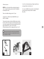
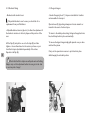
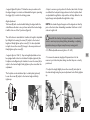
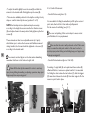
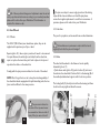
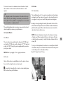
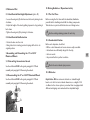
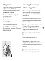
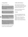
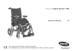
I n v a c a r e Esprit Action
®
User manual
This manual must be given to the user of the product.
Before using this product, read this manual and save for future reference.
®4
NG
EN
Introduction
The Esprit Action4 NG wheelchair is equipped with an Alber e-fix® add-on drive and can easily be transformed into a manual
wheelchair.
There is one (1) option available: Scalamobil (Scalaport in combination with Scalamobil).
Advantages:
• The Esprit Action4 NG with Alber e-fix® add-on drive can be quickly transformed into a manual wheelchair.
• Thanks to the easily removable motor drive unit, the chair is easily transportable.
• The driving characteristics of the Esprit Action4 NG wheelchair can be individually adapted thanks to the Alber e-fix® system.
• Its simple design facilitates care and maintenance of this wheelchair.
• Scalamobil allows effortless climbing of stairs without the need for special adaptations.
• This user manual aims at getting you familiarized with the functions of the Esprit Action4 NG wheelchair.
It contains a description:
• Of the electric motor drive unit
• Of the control elements
• Of the control functions as well as care and maintenance guidelines.
Stamp of the Distributor
Caution
The Esprit Action4 NG wheelchair ALBER e-fix add-on drive has successfully passed the required security tests to meet European and
international standards. This wheelchair equipped with the ALBER e-fix is a class B device for indoor and outdoor use with limited outdoor
capabilities (see §1.2 Driving Safety guidelines).
®
®
This user guide is only valid for use with the electronic ALBER e-fix user guide and the other chosen options and/or Scalamobil.
®
Read the different user guides carefully, ALBER e-fix , Scalamobil (if these options have been chosen) before operating the wheelchair.
®
The older Scalaport models are not compatible with the new Esprit Action4 NG.
The guarantee doesn’t cover damage and malfunctions arising from the disregard of operating instructions.
Your approved Invacare distributor will be delighted to answer your questions.
Esprit Action4 NG is delivered with a pre-programmed maximum speed of 6 km/h.
The maximum speed may not be increased under any circumstances. Doing so will be considered a violation of road traffic regulations.
The launch date for this product is indicated on the CE declaration of conformity.
This product is supplied by Invacare, a manufacturer who respects the environment. It conforms to the EU Working Directive 2002/96/CE on the
management of Waste Electrical and Electronics Equipment (WEEE).
This product may contain substances which could be harmful to the environment if they are disposed of in inappropriate locations (e.g. landfill
sites) and not conforming to the applicable legislation.
The barred trash can symbol is affixed to this product to encourage its recycling to selective collection systems (contact your town hall).
Be environmentally responsible by recycling this product at the end of its useful life.
NOTE: The symbol
identifies general notes which simplify the use of the wheelchair and draws attention to some specific functions.
CAUTION: Pay particular attention to the «Safety guidelines» identified by this symbol
1
SUMMARY
2
1. User Guidelines
1.1. General Guidelines
1.2. Driving Safety Guidelines
2. User Guidelines
2.1. General Information
2.2. Handling Guidelines
2.3 Handling
3. Description
3.1. Performance Checks
3.2. General Condition Check
3.3. Motor Drive Unit
4. Settings
4.1. Seat
4.2. Frame
4.3. Rear Wheels
4.4. Castor Wheels
4.5. Brakes
4.6. Options
5. Equipment
5.1. Motor Drive Unit
5.2. Mounting Plate
5.3. Locking System
5.4. Transformation Kit for Manual Drive
6. ALBER e-fix Electronics
6.1. Electronic Unit
7. Electrical Part
7.1. Batteries
7.2. Motorised Wheels
8. Mechanics
8.1. Hand Control Box Height Adjustment
8.2. Hand Control Box Retraction
9. Motorised Wheels Assembly and Dismantling
9.1. Motorised Wheels Dismantling
9.2. Motorised Wheels Reassembly
®
3
3
3
3
3
4
4
4
4
5
5
6
6
11
12
13
13
14
15
15
15
16
16
16
16
16
16
16
17
17
17
17
17
17
10. Driving Guidelines / Operational Safety
17
10.1. The First Time
17
10.2. Comfortable Position
17
10.3. Obstacles
17
10.4. Going Uphill and Downhill
18
10.5. Parking / Immobilisation
19
10.6. How to Transfer to a New Seat
19
11. Pushing the Wheelchair
19
12. Batteries: Charge, Maintenance and Transport
19
12.1. Guidelines for Charging the Batteries
19
12.2. Charging the Batteries
20
12.3. Guidelines for Battery Maintenance
20
12.4. Transport
20
13. Assembling the Rear Wheels for Manual Propulsion 21
13.1. Assembling the Rear Wheels
21
13.2. Dismantling the Rear Wheels
21
14. General Care and Maintenance
21
14.1. Cleaning the Wheelchair
21
14.2. Maintenance Operations
22
15. Repairs
22
15.1. Checking the front Castor bearings and the Fork
22
15.2. Castor Wheel Removal / Reassembly
23
15.3. Replacing the Tyre and Inner Tube
23
16. Nameplates
23
17.Transport
24
17.1. Transporting the Wheelchair in a Car
24
17.2. Frame Folding and Unfolding
24
18.Technical Specifications
25
19. Inspections
26
20. Warranty
27
21.Tools and Maintenance
27
22. After Sales and Recycling
27
23. Dimensions
28
1. Safety Guidelines
- Maximum Weight:
The maximum weight recommended for the user is 120 kg for
e-fix 22/24" and Scalamobil.
The maximum weight is 125 kg for e-fix 12"
®
®
1.1. General Guidelines
4
The Esprit Action NG with Alber e-fix add-on drive is designed
for indoor use mainly, but can be taken outdoors.
Do not use the powered wheelchair when under the influence of
medication causing drowsiness or confusion.
• Turn off the wheelchair before
- getting in,
- getting out
- raising the armrest.
• Never load the wheelchair into a vehicle with the user sitting in.
4
• Esprit Action NG wheelchair has neither been developed nor
tested to be used as a car seat.
• Respect the authorized load indicated on the cross brace
nameplate.
• Check front wheels tyre pressure regularly (2.5 bars).
• Only use the battery types specified in the technical features.
• During repairs and maintenance be aware that some parts might
be heavy.
®
1.2 Driving Safety guidelines
• This wheelchair is designed to transport one person only.
• If restraining systems (e.g. safety belts) have been installed, use
them for each trip.
• Do not turn off the wheelchair while moving about.
• Don’t change the speed while moving about.
• Do not use on more than 5° slopes.
• Only tackle inclines and obstacles with the backrest in a vertical
position.
• Only go down slopes at most at 2/3 maximum speed.
• Do not go uphill or downhill where the ground is uneven or slippery
or if there is a risk for skidding (Cant, dampness, gravel, ice, grass etc.).
• Proceed through narrow passageways (doors, entrances) at a
reduced speed and with care.
• Always approach obstacles straight on. Pass the front and rear
wheels over the obstacle in one go.
• Maximum height for passable obstacles: 3-4 cm.
• Avoid jerky joystick movements.
• Avoid jerky changes of direction.
• Always use Scalamobil without anti-tip wheels on staircases.
• Do not use the electric drive with Scalamobil.
• Always reposition the anti-tipping castor wheels after dismantling
Scalamobil.
2. User Guidelines
2.1. General Information
The e-fix add-on drive must be turned off whilst getting in and getting
out as well as while handling items.
Figure A: Do not step on the footrest while getting into or out of the
wheelchair.
Figure B: Do not lean out of the wheelchair.
Figure C: Do not try to pick up items from the ground if this requires
placing your torso between your knees.
®
A
B
C
D
E
3
Figure D: Do not try and reach items when this requires sitting at
the front of the chair.
Figure E: Do not try and reach items when this requires leaning
backwards over the backrest.
2.2. Handling Guidelines
4
Figure A: To transfer to a new seat, move the wheelchair as close as
possible to the new seat.
Figure B: Always approach obstacles straight on.
Pass the front and rear wheels over the obstacle in one go, do not
stop half way through.
Figure C: Never try to go up or down slopes where the ground is
damaged or slippery or if there exists a risk for skidding (dampness,
gravel, ice, grass etc.).
A
B
C
4
3. Description of Esprit Action NG
3.1. Introduction
Your wheelchair, while benefiting from standard pre-adjustments
before your purchase, must be specifically adapted to meet your
own needs.
The following detailed paragraphs outline the different features and
possible adjustments, as well as the available options.
Some adjustments can be performed by you, while others will
require the intervention of your Distributor.
Important: based on the chosen model or options, your new
4
Esprit Action NG wheelchair may or may not be equipped with
elements or options described in the following pages.
Non contractual photos and illustrations.
Backrest fittings
Push handles
Box hand
control
2.3. Handling (Photo 1)
• Turn on the hand control box with the START/STOP switch (A).
• Select the speed with the speed potentiometer (B).
• Moving the joystick (C) allows the power wheelchair to roll in the
corresponding direction.
Armrest
Cushion
B
Rear wheel
motorised
A
The magnitude of the joystick movement determines the speed of
the chair.
Avoid jerky joystick movements. There is a risk of the chair
tipping.
Backrest
Fittings seat
Legrest hanger
swing away
Axle of
rear wheel
C
Folding frame
1
2
Castor wheels
Footrest
!
This is a warning symbol, it is essential to respect
the guidelines provided in these paragraphs in order to
avoid any injury to yourself and those around you.
This symbol indicates information which could be of
interest to you, please contact your distributor.
3.2 General Condition Check
Your wheelchair is composed of different parts and the most
important parts are referred to in this manual. We suggest that
you familiarize yourself with the following terms in order to
understand how your wheelchair works:
• The seat comprises the seat and backrest fittings, the backrest
and the armrests. Together they are designed to provide optimal
comfort;
• The swing away legrest. It comprises the support piece
between the frame and the footrest, it rotates for ease of transfers
and dismantles for transport;
• The footrest includes the adjustable rail and the footplate which
supports the foot;
• The folding frame includes the lateral mountings and the
folding system including the seat rails.
These parts constitute the frame, which is the carrying element of
the wheelchair, their overall strength has been carefully considered.
Tested at 125 kg for 380-605 mm widths and at 80 kg for 305-380
mm widths;
• The rear wheel comprises the wheel, the axle and the handrim.
The rear wheels guarantee the stability of the back and are used
for hand propulsion with the handrims;
• The castor wheel comprises the front wheel and the fork. The
castor wheels ensure front contact with the ground and determine
the direction through the orientation of the forks;
• The handbrake is a parking brake. The two handbrakes are
used to immobilise the chair during prolonged stops (in manual
propulsion);
3.3. Motor Drive Unit
• electric drive unit, 2 x 12" or 22/24" motorised wheels
• hand control box
• junction cables
• battery pack.
5
4. Settings
4.1.2. Types of backrests
4.1. Seat
- Mid-height folding backrest (photo 3): in order to reduce the
volume during transport, activate the lever (B) by pulling or pushing
on it and fold the top part of the backrest.
To return to the initial position, bring back the top part to a
vertical position, it will snap back into place automatically.
4.1.1. Seat fittings
- Standard seats:
• Nylon seat fabric with or without Velcro: the Velcro strips are
necessary for properly holding the cushion in place, ensure that it
is correctly placed on the seat.
6
The standard seats are not adjustable; if they become loose,
you should ask their replacement from your Distributor. Invacare
offers a range of seat cushions adapted to your needs, please
consult your Distributor.
!
Always use a fabric equipped with Velcro strips with a
cushion, this is to avoid any slippage and risk of falling!
! Always check that the backrest is correctly locked into
position before the user gets in the chair in order to avoid any risk
of injury!
- 0°-30° Reclining backrests with standard 30/41/43 cm and 47/49/
51 cm heights.
They are now equipped with a new trigger handling system.
The reclining angle is easily adjustable, allowing an always
comfortable resting position.
Pull on the triggers (A) simultaneously to ensure the same angle on
the two sides and release the triggers at the chosen angle (Photo
4A).
B
A
3
4A
In order to avoid any injury, keep your fingers away from any
moving parts (levers, mechanisms etc.)!
• Mechanical version
NOTE: Push on the backrest before activating the triggers in
order to release the locking system (automatic locking safety
mechanism) (Photo 4B)
So as not to destabilize the user position, avoid activating the
levers (A) during a sideways transfer, for example!
(Photo 5B)
There are 4 available reclining positions, 10° apart.
• Pneumatic version (Photos 5A and 5B). 30/41/43 cm and
47/49/51 cm Heights
The pneumatic springs provide help with lifting, always undertake
this action with the user sitting in the chair. The pneumatic springs
version may be equipped with optional pushing handles which are
height adjustable for the comfort of the attendant.
Continuous adjustment of the reclining position from 0° to 30°
7
!
This action should only be carried out by an attendant.
Always verify that the backrest is correctly locked in order to
ensure complete user safety.
A
4B
5A
5B
4.1.3. Backrest fittings
4.1.4. Legrest hangers
- Backrests with standard cover:
- Standard hangers (photo 7) : they are retractable for transfers
and removable for transport.
If the padded backrest cover loosens, you should ask for a
replacement from your Distributor.
• Adjustable backrest tension (photo 6): it allows the adjustment of
the backrest curvature to the body shape and the position of the
user.
8
Lift the flap (A) and pull on one or both straps (B) and then
tighten or loosen them based on the version you have on your
chair. Each strap is adjustable independently of the others.
Reposition the flap (A).
Operate lever (A) by pushing sideways and rotate outwards or
inwards in the event of reduced space.
To return to the initial position, bring the legrest hanger back into
line, it will snap back into place automatically.
To remove the legrest hanger, simply pull upwards once you have
unlocked the system.
Carry out the operation in reverse to put it back into place
whilst keeping the unlocked position.
!
Check that the Velcro strips are well positioned and holding.
Always carry out this adjustment before the user gets in the chair
to avoid any risk of injury!
B
A
A
6
7
- Legrests Figure 8 & photo 9: follow the same procedure as for
the legrest hangers to retract and dismantle the legrest, operating
the trigger (A) to unlock the locking system.
Angle adjustment
Turn lever (B) with one hand while holding the legrest with the
other. Release the lever once you have reached the desired angle,
it will lock in one of the 7 positions (figure 8).
The calf cushion is retractable for transfers; its height is adjustable
by sliding after loosening the screw (C): adjust to the desired
height and firmly tighten up the screw (C). It is also adjustable
in depth: loosen the screw (D), change to the new position and
firmly tighten up the screw (D).
- Legrests (photos 10 & 11) : they are height adjustable and can
be equipped with a fixed or articulated footplate (optional); the
footplate can be flipped-up for transfers. Loosen the screw (A) to
adjust to the desired height, firmly tighten up the screw after the
adjustment.
The footplate can be articulated by a toothed plate (optional),
loosen the screw (B), adjust to the desired angle and firmly
tighten up.
- Straps: to ensure a good position for the feet, two kinds of straps
are offered; the heel push strap positioned on the footplate, fixed
or adjustable through Velcro strips and the calf strap affixed to the
legrest hanger and adjustable through Velcro strips.
NOTE: the standard legrest hangers and the legrests are fixed by
pair on the chair; when dismantling, remember that there is a left
side and a right side!
! Never lift the chair by the legrest hangers or the armrest! In
order to avoid any injury during folding, dismantling or adjusting
operations, keep your fingers away from any moving parts!
4.1.5. Multi-adjustable armrests (photos 12 & 13)
• To remove the armrest, simply pull it upwards, and do the
reverse to put it back in place, taking care that they are correctly
positioned.
• To adjust the height, slightly loosen the screw (A) and adjust to
the desired height using the preset adjustment holes. Firmly tighten
up.
B
A
B
8
A
D
C
9
10
11
9
4.1.6. Comfort Dartex seat
• To adjust the width, slightly loosen the screw (B) and slide the
armrest to the desired width. Firmly tighten up the screw (B).
• There are two available positions for the depth according to body
shape or comfort desired by the user (positions C or D).
NOTE: the lateral protection adjustment may be necessary
according to the height chosen, unscrew the four fixation screws
(E) and replace them in the new position, firmly tighten up the four
screws (E)
These armrests are fixed on an adjustable carrier (in 2 parts)
which allows you to reduce the looseness and facilitates removal
during transfers, the 4 screws should be tightened or loosened (F)
according to the desired result
10
The armrests are fixed by pair on the chair, when dismantling;
remember that there is a left side and a right side!
!
Never lift the chair by the armrests! In order to avoid any
injury during folding, dismantling or adjusting operations, keep your
fingers away from any moving parts!
- Comfort Dartex seat (photo 14):
It is removable for folding the wheelchair; just lift up the seat and
put it aside, then hold the 2 chair rails and pull upwards.
Do the reverse for unfolding (see § 2.1.1).
The cover and padding of this seat is subject to wear, contact
your Distributor for any replacement.
! Take care that the seat is well positioned on the 3 Velcro seat
strips to ensure the safety and comfort of the user. In order to
avoid any injury when folding and unfolding, keep your fingers away
from any moving parts!
- Comfort Dartex backrest (photos 15 & 15A):
Consisting of a rigid shell (A) and a preformed foam cushion (B)
affixed with Velcro, it ensures an optimal comfort. It is removable
for folding the chair: release the two buttons (C), slide the triggers
(D) inwards and release the hooks (E) from their supports. Do the
reverse to put it back in place.
A
A
D
E
B
B
C&D
12
E
F
13
14
15
15A
C
!
This action should only be carried out by the attendant.
Always check that the backrest is correctly locked in order to
ensure complete user safety.
Check that the Velcro strips of the backrest cushion are well
positioned and have a good grip.
In order to avoid any risk of injury keep your fingers away from any
moving parts!
NOTE: To clean the Dartex cover, use a soft cloth soaked in
alcohol.
- Comfort Dartex head rest (photo 16) :
It is removable by completely loosening the button (A). The height
is adjustable by slightly loosening button (A), adjust to the desired
height and tighten gently (A).
The reclining angle, depth and height of the cushion are also
adjustable in by simultaneously operating lever (B) and the screws
(C).
NOTE: take care when positioning the indexable lever so that it
isn’t in the way or could cause injury for the user or the attendant.
C
! Do not adjust the headrest while the user is leaning against
it and check its attachment the backrest to avoid any risk of injury.
4.2. Frame
4.2.1. Sides
The sides or lateral support are mainly designed for receiving the
castor and rear wheels.
These wheel supports allow three (3) height positions and two
longitudinal positions:
4.2.2. Folding system
380-605 mm Widths:
It consists of two double cross-braces which integrate the seat
rails.
To fold and unfold your wheelchair, see chapter A General
Information, paragraph 2.1.
11
305-380 mm Widths:
It is equipped with a telescopic cross-brace (figure 17) which
offers 4 seat width adjustments from 305 to 380 mm.
The seat and backrest covers are also width adjustable.
�����������
�����������
�����������
�����������
B
A
�
�
16
����
���
���
���
���
��
���
���
���
���
�
����� ����� ����� �����
�
����� ����� ����� �����
17
!
All of these positional changes and adjustments must be carried
out by a professional technician according to your medical prescriber;
please ask for advice from your Distributor. This information is
provided for reference only.
The tyres are subject to wear, rough grounds and the driving
styles will also have an influence on their life span; please
ensure their regular replacement to avoid the inconvenience of
punctures, please ask for advice from your Distributor.
4.3. Rear Wheels
4.3.2. Handrims
4.3.1. Wheels
They are for propulsion, and are made from anodized aluminium.
The 22/24" (550/610 mm) rear wheels have spokes, they can be
supplied with a puncture proof tyre or band.
12
Repairs (photo 18) : when a tyre is punctured it needs to be removed
for repair. Remove the whole (tyre and tube) from the wheel rim,
repair or replace the inner tube, put it back in place in the tyre and
reposition the whole on the wheel rim.
Comply with the tyre pressure indicated on the side of the wheel.
NOTE: Don’t forget that in order to keep the interchangeability of
the wheelchair wheels equipped with rapid dismantling axles, the two
tyres must be inflated to the same pressure.
!
The handrims are in permanent contact with the hands;
regularly check that they are not damaged!
4.3.3. Axles
The axles link the wheels to the frame and can be quickly
dismantled (photo 19):
- Quick-release axles (photo 20): push in button (A) and insert
the axle into the wheel hub. Position all of it in the bearing (B) of
the multi-adjustable wheel support until it locks into position.
The locking balls (C) should protrude from the bearing and there
should not be any significant lateral looseness.
A
B
! The pressure indicated on
the sides of the tyre must never
be exceeded or there is a risk of
injury if the tyre were to burst!
18
A
19
20
B
C
To reduce looseness to a minimum, remove the axle and adjust
the nut with a 19 mm wrench, lock the axle with an 11 mm
spanner.
!
Regularly monitor the cleanliness of the axle and the stop
balls. To avoid any risk of falling, it is absolutely essential that the
button (A) and the stop balls are completely clear to ensure that
the rear wheels are completely locked.
The quick dismantling axle is a precision piece, avoid shocks and
clean it regularly to ensure a good performance.
4.4. Castor Wheels
4.4.1. Wheels
The castor wheels are available with a diameter of 8" (200 mm)
and a width of 2" (50 mm) or with a diameter of 7" (172 mm) and
a width of 1 3/8" (32 mm), they can be supplied with a puncture
proof tyre or band.
NOTE: Refer to paragraph 15 for ongoing maintenance.
4.5. Brakes
4.5.1. Handbrakes
The handbrakes (photo 21) are used to immobilise the chair during
prolonged stops. They cannot to be used to slow down the chair or
as a support to carry out a transfer. They must be used together.
Braking is done by pushing the handle (A) towards the front of the
wheelchair. Handle (A) folds back to facilitate transfers. Beforehand,
pull the handle upwards. Once the brakes have been activated, the
chair should not be able to move.
NOTE: the brake adjustments depends on the diameter and type
of wheels used. After repairing a flat tyre or after wear of the tyre
or band, it may be necessary to adjust the brake or brakes with the
screws (B).
To carry out the adjustment, loosen the two screws (B) and slide all
of the brake until you reach between the wheel and the brake pad in
an unlocked position a value (X) as follows:
Band X = 4 mm - Tyre X = 5 mm
4.4.2. Forks
Various fork positions are available based on the options chosen
for seat-to-floor height, castor and rear wheels.
B
A
If you wish to change the fork or castor or rear wheels, please
ask for advice from your Distributor.
X
21
13
4.6.2. Safety options
!
Firmly re-tighten the screw (B) after adjustment. Keep your
fingers far away from all moving parts in order to avoid any risk of
injury!
4.6. Options
4.6.1. Seat options
- Straight backrest stretcher (photo 22): it ensures that tension is
maintained for the backrest fittings and allows a better ergonomic
position for the attendant while pushing the wheelchair.
NOTE: It is foldable to fold the chair, slightly loosen button (A), pull
upwards and turn it until a vertical position is reached, along the
backrest.
14
To put it back in place, do the reverse and firmly tighten up button
(A) while ensuring that button (B) is tightened well.
! Avoid lifting the chair by the stretcher! There is a risk of the
stretcher unlocking while pushing upwards.
Keep your fingers far away from any moving parts in order to avoid
any risk of injury!
B
A
22
• Postural belt with buckle lock (photo 23): to lock the buckle, place
part (A) into part (B), to open it press on (C). Based on the user
body size, pull on one or the other of the strap extremities (D)
passing it through the two buckles (E).
It is important that both buckles (E) are used. If not there is a danger
that the belt will slip.
If the belt gets loose, it can be adjusted by tightening the strap (F)
passing it through the buckle (G).
Ensure that the user is well seated at the back of the seat and that
the pelvis is well positioned.
Position the belt under the ilium crest. Adjust the length in such a
way that a hand can fit between the belt and the body of the user.
It is recommended that the belt locking mechanism is in a central
position so adjust the strap on each side.
These adjustments must be checked each time the belt is used.
C
B
A
D
E
F
G
23
!
!
The belt fixation must be conform to the scheme enclosed
with each belt delivery; the belt should be mounted and adjusted
by your regular dealer.
Ensure that the stud is well positioned in the preset adjustment
hole to avoid any risk of falling.
Never forget to fold the anti-tipping castor wheels once they are
retracted.
Please be careful that the belts don’t get caught in the spokes of
the rear wheel. The postural belts must not be used as safety belts
in a car.
5. Equipment
• Anti-tipping castor wheels with foot rest (photo 24 and figure
25) :
This version includes a support for helping to tilt.
Adjust to the desired height (while respecting the recommended
distance) by operating the button (A figure 25).
!
10
5.1. Motor Drive Unit (photo 26)
4
The electric drive unit of the Esprit Action NG includes the
following components:
• 2 x 12" or 22/24" motorised wheels (A)
• electronic center (B)
• the battery packs (C)
15
m
m
The recommended distance between the castor wheels and
the floor is 3-5 centimeters, this adjustment is necessary in relation
to the rear wheel position and diameter.
Operate the button (A figure 25) and adjust the desired distance
using the preset adjustment holes.
5.2. Mounting Plate (photo 27)
The mounting plates to the right and left of the wheelchair frame
are equipped with two housings (A) for the rear wheel axle and (B)
for the electrical connection which allow fitting of the 2 motorised
wheels.
C
A
A
24
A
25
!
3 cm mini
26
A
B
C
27
B
The bearing supports for fixing the manual propulsion wheels are
positioned above (C) for e-fix 12" and in the place of the motorised
wheels for e-fix 22/24".
6. ALBER e-fix Electronics
Refer to the additional e-fix guide paragraph 2.1 Wheel assembly and
paragraph 2.2 Removing the wheels.
Refer to the additional e-fix guide paragraph 2.1 Wheel assembly and
paragraph 2.2 Removing the wheels.
The electronic center of Esprit Action NG is found in the electric
drive unit. Called the ALBER e-fix system, it is responsible for
controlling the movement functions.
As well as controlling the driving, ALBER e-fix is also responsible
for controlling the wheelchair’s electrical system.
Any system failure is indicated by a flashing light in the hand control
box (status indicator).
5.4.Transformation Kit for Manual Propulsion (optional)
For more information, see the ALBER e-fix user manual!
®
®
®
®
5.3. Locking the Motorised Wheels
4
®
®
®
®
4
16
6.1. Electronic center
This kit allows the transformation of the powered Esprit Action NG
wheelchair into a manual propulsion wheelchair.
It contains the 22/24" rear wheels (A) which are essential for the
transformation as well as two hand brakes (B). (photo 28).
Refer to paragraph 4.5.1 for adjusting the brakes.
7. Electrical Part
7.1. Batteries (photo 29)
All the power supply for the power wheelchair is provided by two
12V batteries (A). (12 Ah standard, 17 Ah optional).
They are housed in a box (B). To facilitate removing and
repositioning the batteries, it is possible to remove the housing box
from the wheelchair frame (self gripping strips).
A
A
A
7.2. 12" or 22/24" Motorised Wheels
The motorised wheels are equipped with automatic brakes.
A mechanism allows disengaging of the motors to allow the chair to
be pushed.
28
The motor brakes are off when the chair is pushed.
See the additional ALBER e-fix guide.
®
29
8. Mechanical Part
10. Driving Guidelines / Operational safety
8.1. Hand Control Box Height Adjustment (photo 30)
10.1.The First Time
• Loosen the wing nut (A) which secures the box by turning it anticlockwise.
• Adjust the height of the box by pulling it upwards or by pushing it
back down.
• Tighten the wing nut (A) by turning it clockwise.
Before moving the first time with the wheelchair, familiarize
yourself with its handling and with all the driving components.
Take the time to practice all the functions and driving modes.
8.2. Hand Control Box Retraction
• Rotate the box onto the side.
• Bring it back to its starting position. A spring will lock it in its
original position.
9. Assembling and Dismantling the 12" or 22/24"
Motorised Wheels
Use the existing retaining systems for each trip.
10.2. Comfortable Position
Before each departure, check that:
• All the control elements and accessories are easily accessible.
• the batteries are sufficiently charged for the trip,
• the horn works
• the postural belt is in perfect condition.
9.1. Dismantling the motorised wheels
See the additional ALBER e-fix guide, paragraph 2.1 Wheel
assembly and paragraph 2.2 Removing the wheels.
®
9.2. Reassembling the 12" or 22/24" Motorised Wheels
See the additional ALBER e-fix guide, paragraph 2.1 Wheel
assembly and paragraph 2.2 Removing the wheels.
®
A
30
Check the castor wheels tyre pressure
10.3. Obstacles
4
Esprit Action NG can surmount obstacles or sidewalk height
based on to the front castor wheel dimensions, i.e. a height of 3-4
cm. Based on the chosen options your wheel chair is equipped with
different anti-tipping castor wheels with an adjustable height.
17
10
m
m
e-fix : Height adjustment for the anti tipping castor wheels
(photo 31 and figure 32)
®
Never approach obstacles at an angle. The chair risks tipping
and only pass over obstacles with the backrest in a vertical position.
Lift up the spring button (A) and choose one of the 2 available
heights, 3 or 5 cm. Make sure that the anti-tipping system is locked
in its new position
Scalamobil: See the description in the Scalamobil guide
Always reposition the anti-tipping castor wheels after
dismantling Scalamobil (risk of falling or tipping).
18
Driving guidelines (figure 33):
• Always approach the obstacle or sidewalk slowly and straight on
(maximum of 3 to 4 cm).
• Increase the speed just before the castor wheels or the lifting
device comes in contact with the obstacle.
• Only reduce speed after the rear wheels have also surmounted the
obstacle.
10.4. Going Uphill and downhill
4
Esprit Action NG can securely travel uphill on inclines lower
than 5° (figure 34). There is a risk of tipping when the inclines are
steeper. Follow the course of the incline; do not travel in a zigzag
pattern.
Only go uphill or downhill with the backrest in a vertical
position and the anti-tipping castor wheels correctly secured.
Go downhill at most at 2/3 maximum speed.
Do not go uphill or downhill where the ground is rough
or slippery or if there is a risk for skidding (dampness, gravel, ice,
grass etc.).
Increased risk of tipping when getting out of the chair on a
slope.
31
A
32
33
34
3 cm mini
10.5. Parking / Immobilisation
To park your vehicle or in the event of a prolonged immobilisation,
turn off the hand control box (ON/OFF switch)
The chapter «Circulation» describes the different operations.
10.6. How to Transfer to a New Seat
• Move as close as possible to the new seat (figure 35).
• Turn the wheelchair power off.
• Remove/raise the armrest.
• Slide on the new seat.
11. Pushing the Wheelchair
In order for accompanying person to manually push
4
Esprit Action NG, the motors should be disengaged.
Refer to the additional e-fix guide, paragraph 7.2 Driving with the
e-fix wheels in manual mode.
®
®
12. Batteries: Charging, Maintenance and Transport
12.1. Guidelines for Charging the Batteries
Follow the charger user guide provided with the wheelchair. If the
wheelchair is equipped with different options (e-fix , Scalamobil)
each battery pack must be recharged with its proper charger, see the
appropriate Alber guide.
®
It is possible to recharge the batteries overnight as the charger
is equipped with an automatic switch off system which prevents the
batteries from overcharging.
During the charging procedure, the wheelchair must be powered
off. This saves any excess use of power and ensures that the
batteries are fully charged. When the wheelchair is plugged in, the
charging procedure cannot be automatically interrupted.
New batteries should be charged for 12 hours before first time
use.
Always recharge the batteries after the last trip.
Batteries that are almost completely discharged should be
recharged for at least 16 hours. If this procedure isn’t possible on
three successive occasions, the batteries should be charged once for
over 24 hours.
Room temperature should be 10-30 °C while recharging.
Charge time is longer when the temperature is below 10 °C.
35
19
12.2. Charging the Batteries
12.3. Guidelines for Batteries Maintenance
Always refer to the charger user manual.
• Only store the batteries when they are fully charged.
• Their storage temperature must be between -40°C and +50°C.
• In the event of a prolonged immobilisation (over 4 weeks), the
wheelchair batteries must be recharged once a month.
There is a risk of explosion and destruction of the batteries
should an incorrect charger be used. Always use the charger
supplied with the wheelchair.
20
This allows them to hold their full charge and avoids any
deterioration by spontaneous discharge.
There is a risk of injury by electrocution and of destruction
of the charger if it is wet. Protect the charger from humidity.
12.4.Transport
There is a risk of injury by short-circuit and of electrocution
if the charger has been damaged. Do not use the charger if it has
dropped on the floor or if it is damaged.
Tests have allowed the determination of a battery category:
4
Batteries which equip Esprit Action NG are not "dangerous
materials".
This classification relates to the following regulations:
- Regulation for road transport of dangerous goods GGVS
- Regulation for rail transport of dangerous goods
- Regulation for air transport of dangerous goods IATA/DGR
There is a risk of fire and of injury by electrocution in the
event a damaged extension cord is being used. Use an extension
cord only when absolutely necessary! If you must use one, you
must be sure that it is in perfect condition.
For more information refer to the Alber e-fix and/or Scalamobil
user manual or contact your local Invacare representative.
®
13. Assembling the Rear Wheels for Propulsion Manual
13.2. Dismantling the Manual Rear Wheels
13.1. Assembling the Manual Rear Wheels
• Push in the quick dismantling axle button (A) and remove the
axle from the wheel bearing supports (B) of the mounting plate.
• Remove the hand control box and the motorised wheels.
• Push in the quick dismantling axle button (A) and introduce
the axle (A) into the bearing support (B) of the mounting plate.
(photos 36 and 37).
14. General Care and Maintenance
14.1. Cleaning the Wheelchair
Follow the following points for cleaning the wheelchair:
• Clean the hand control box and the seat and backrest covers
only with a damp cloth and a gentle cleaning product.
• Only use cleaning products which do not contain abrasives.
• Do not direct streams of water directly onto the electronic
components.
• Do not use a high pressure cleaner.
Verify that the stop balls (C) protrude from their housing.
Clean the quick dismantling axle (A) as well as the bearing
support (B) of the castor wheel before assembling them. Dirty
components lead to premature wearing of the bearings.
Carefully check the manual brake adjustments according
to the 22/24" rear wheel type mounted on the wheelchair (see
paragraph 4.5.1).
B
A
A
36
B
C
37
21
14.2. Maintenance Operations
22
¨ ý ¨
¨ ý ¨
Backrest and seat covers
• Check that they are in perfect condition.
¨ ý ¨
Armrest and armrest pads
• Check the condition of the armrest.
• Check that all joints move easily.
• Check that the armrest deadlocks are working correctly.
¨ ý ¨
¨ ý ¨
ý ¨ ¨
Footrest
• Check that the deadlock device is working correctly.
• Check the condition of the footplates.
¨ ý ¨
¨ ý ¨
Tyres and tyre bands
• Check that the wheels tyre pressure is correct (2.5 bars).
• Make sure the wheels and bands are showing no signs of damage
(cracks, etc):
Forks / castor wheels
• Make sure the castor wheels turn freely.
• Make sure the fork bearings are securely fixed.
ý ¨ ¨
¨ ý ¨
ý ¨ ¨
¨ ý ¨
Motorised rear wheels
• Make sure the electric drive unit locking system moves easily and
works correctly.
• Make sure the bolts are securely fixed in the mounting plate.
• Check that the rear wheel screws are completely tightened.
• Make sure the rear wheels aren’t bent after a side impact.
ý
ý
¨
¨
General inspection by the approved Invacare distributor.
¨ ¨ ý
Before dismantling the wheels, lift the wheelchair up, support
and immobilise it to ensure that it doesn’t move.
Lift the chair up and place a support (A) under the frame to
ensure that it doesn’t fall. (figures 38 and 39). Before starting to
dismantle the wheels, ensure that the wheelchair is powered off.
15.1. Checking the Castor Wheel Bearings
Spin the left and right castor wheels.
If the wheel spins freely for some time: the bearing is in good
condition.
- If the wheel stops spinning as soon as you let go: have the wheel
checked / replaced by the approved distributor.
Checking the fork bearing
Hold the fork by the sides and move it forwards and backwards.
- Impossible to move the castor fork backwards in its bearing: the
bearing is in good condition.
- The fork moves forwards and backwards in its bearing: Have the
bearing checked / replaced by the approved distributor.
¨
¨
¨
¨
Turn
¨
¨
ý
ý
Please contact your distributor for all repairs; they will be
responsible for returning your chair to Invacare After Sales
service, if necessary.
®
Year
Month
Frame
• Check that the cross-braces are not damaged.
• Check that all cross-braces joints for are not loose and that they
move easily.
Week
In case of problems during maintenance or if you spot damages or
anomalies at your Esprit Action4 NG, immediately contact your local
Invacare representative
15. Repairs by the user/attendant
38
39
Move in the
arrows direction
15.2. Removal / Reassembly of the Front Castor Wheel
(photo 40)
• With the help of a tyre remover, lift the first side of the tyre (C)
above the rim
• Remove the electric drive unit from the frame.
• Place the frame on a clean surface with the push handles
backwards.
• Loosen nut (A) with a 5 mm Allen wrench while holding screw
(B) with a second 5 mm Allen wrench.
• Remove screw (B) from the fork.
• Remove the wheel from below.
Assembling/replacing the inner tube (photo 41)
• Place the inner tube (B) inside the tyre and inflate it slightly.
• Ensure that inner tube (B) and valve (A) are correctly positioned.
• Put the opposite side of the tyre (C) on the rim, starting from
the side opposite valve (A).
• Ensure that the inner tube (B) isn’t caught between the rim and
the tyre (C).
• Inflate the inner tube to the recommended pressure written on
the tyre (usually 2.5 bars).
• Ensure that the tyre (C) is correctly placed on the rim.
To reassemble front wheel proceed in the reverse order.
15.3. Replacing the Tyre / Inner tube (figure 41)
• Unscrew the valve cap (A).
• Let out the air from the inner tube (B) by pushing on the spring
pin.
• With the help of a tyre remover, free the tyre (C) from the rim,
starting on the valve side.
• Remove the inner tube from the tyre.
Replacing the tyre
• With the help of a tyre remover, free the opposite side of the
tyre from the rim.
B
40
B
41
The wheelchair nameplates provide important technical
information; they make chair identification easier and help with the
ordering of replacement parts.
e-fix :
They are found on the inner side of the 2 motorised wheels and
on the battery pack connection interface.
®
Scalamobil:
They are located on the rear side of the motor-battery unit
The serial numbers are stuck to the folding cross-brace as well as
on the interface.
C
A
16. Nameplates
A
23
24
17.Transport
17.2. Frame Folding and Unfolding
17.1.Transporting the Wheelchair in a Car
Transportation is carried out with separate elements (photo 43).
Refolding the wheelchair (figure 44)
Without its user:
Drive or push the power wheelchair into the vehicle with the help of
an appropriate ramp.
Once the wheelchair is inside, immobilise it with the security belts as
shown (photo 42).
• Remove the footrest and the electric drive unit.
• Hold the seat cover by the middle and pull upwards as far as
possible.
• Completely close up the entyre frame, holding it by the armrests.
Before each departure, ensure that:
• the motors are engaged
• the hand control box is turned off.
Be careful with moving parts when folding and unfolding the
chair. Risk of crushing.
For safety reasons, loading the wheelchair with the help of a
ramp should always be done without its occupant sitting it. There is a
risk of the chair tipping.
• Open the frame to the fullest, holding it by the armrests.
• Pull the cross-braces apart by the exterior tubes until the frame
clicks into place (stop).
• Reassemble the electric drive unit and the footrests.
Unfolding the chair (figure 45)
During transport the battery pack must imperatively be
dismantled, there is risk of injury in case of impact.
Position of the
safety belts
42
43
44
45
18.Technical Specifications (Adult = Std, Child = Jr)
for the wheelchair equipped with e-fix 12"
Tyre pressure:
2,5 bars
(front castor wheels only)
Wheelchair classification:
Class B (indoor and limited
outdoor use)
Turning radius:
Std : 930 mm
Jr : 760 mm
Seat width:
Std : 380 /405/430/455
485/505/555/605 mm
Jr : 305/330/355 mm
Driving speed:
6 km/h max.
Max driving range:
14 km (12 Ah)
26 km (17 Ah)
®
Seat depth
Std : 400/450/500 mm
Jr : 325/375 mm
Empty weight:
Seat height without cushion:
Std : 460/485 mm
Jr : 460 mm
Std : 45 kg
Jr : 42 kg
Maximum load (payload):
Total height:
Std : 1020 mm
Jr : 915 mm
Std : 125 kg
Jr : 80 kg
Uphill range:
Total width:
Seat width + 170 mm
up to 5° max
on stable ground
Total length, without footrest:
Std : 800/850/900 mm
Jr : 695/745 mm
Ground clearance:
45 mm
Total length, with footrest:
Std : 1000/1050/1100 mm
Jr : 900 mm
Passable objects:
Std : 40 mm
Jr : 30 mm
Armrest / seat height (mm):
210 to 345 m by 15 mm
Electrical installation:
24 V
Armrest width adjustment:
+ 60 mm
Batteries:
Footrest length:
Std : 330 à 480 mm
2x 12 V 12 Ah batteries
(17 Ah optional)
Battery charger:
240 V / 24 V - 3 A
Backrest reclining position range:
0° à 30°
Front tyre dimensions:
Std : 8" x 2"
Jr : 7" x 1 3/8"
Electronic center:
ALBER e-fix System
Authorized storage temperature:
-40° C to +65° C
Rear tyre dimensions:
12".1/2 x 2".1/4"
Authorized room temperature:
-20° C to +40° C
25
19. Inspections (Operations to carry out)
In case of problems during maintenance or if you spot damages or
4
anomalies at your Esprit Action NG, immediately contact your
local Invacare representative
Regularly tighten all the fixation screws.
Frame
• Check that the cross-braces are not damaged.
• Check all joints of the cross-braces to ensure that they are not
loose and that they move easily.
26
Backrest and Seat Covers
• Check that they are in perfect condition.
Armrests and Armrest Pads
• Check the condition and fastening of the armrest pad.
• Check the armrest bearing to ensure that it is not excessively
loose.
• Make sure the armrest deadlocks are working properly.
Standard Hand Control Box
• Check its overall condition and fastening.
• Check all joints of the rotating mechanism (optional) to ensure
that they move easily.
Footrest
• Check that the locking system works properly.
• Check all the bearings to ensure that they are not excessively
loose and that they move easily.
• Check the condition of the footplates.
Tyres and Tyre Bands
• Check the tyre pressure (2.5 bars).
• Check the wheels and bands are showing no signs of damage
(cracks, etc.).
Forks/Castor Wheels
• Check that the forks are securely fastened to the frame.
• Check that the forks/castor wheels are showing no signs of
damage.
• Check the fork bearings.
• Check the front castor wheel bearings.
Motorised Rear Wheels
• Check that the motorised wheel lock moves easily and works
properly.
• Check that the bolts are securely engaged in the mounting plate.
• Check that the rear wheels are not distorted following a lateral
impact.
• Clean the motor contacts.
Trial Run
• Smooth start/turn.
• Check the brakes.
20. Warranty Conditions Summary
Contractual warranty
Invacare wheelchairs have a 2 years warranty against all
manufacturing defects arising from a materials or construction
defect, starting from the delivery day.
®
This warranty is explicitly limited to a return in working condition
or a free exchange (parts and labour) of parts recognized as being
defective in the Distributor’s workshop after agreement from
Invacare , being specified here that this return in working condition
or exchange can be achieved with new parts, from new sub
assemblies or standard exchange of said parts after final judgment
from Invacare .
®
®
Applicability Conditions
To activate this warranty, contact your Invacare Distributor and
present this duly completed certificate. Postage and packing costs
as well as transport costs are at borne by the purchaser. The
distributor may or may not bear these costs depending on the sale
conditions they use.
®
The warranty applies provided that:
• The wheelchair is repaired in the Distributor or Invacare local
workshop.
• The periodic checks figuring on the back of the warranty
certificate have been carried out in a timely manner in said
workshops.
®
• From dismantling, repair or modification carried outside of the
Distributor or Invacare local workshops.
• If you cannot provide proof of purchase.
®
The warranty does not cover:
• Replacement of parts subject to normal wear and tear resulting
from the use of the wheelchair (tyres or bands, brake pads,
armpad, seat and backrest fittings, footrest plates, batteries, etc.)
21.Tools for Adjustments and Normal Maintenance
(not supplied)
Function
Tool
Brake
Footrest tube
Footplate
Armrests
Armrest
Front wheel
Quick dismantling axle
5 mm Hex wrench (Allen)
5 mm Hex wrench (Allen)
5 mm Hex wrench (Allen)
5 mm Hex wrench (Allen)
T20 Torx wrench
5 mm Hex wrench (Allen)
11 / 19 mm Flat wrench
22. After Sales and Recycling
• You must use Invacare spare parts available from all Invacare
Distributors.
• Please contact your distributor for all repairs; they will be
responsible for returning your chair to Invacare After Sales
service, if necessary.
• Recycling: The metallic and plastic parts can be recycled (reuse of
metal and plastic materials).
The disposal must be carried out according to applicable local and
national regulations. For further information on waste treatment
organizations in your area, please contact your town hall.
®
®
®
Limitations
We draw your attention to the fact that this warranty is not
applicable in the event of:
• Accidents, falls, shocks, abnormal use.
• Normal wear and tear arising from use of the wheelchair.
• Poor maintenance of the wheelchair.
27
23. Dimensions
Picture
Min/Max
Description value
Seat effective
width (mm)
Overall
width (mm)
Width of
folded
wheelchair
(mm)
28
Total
height
(mm)
Height from
ground to
back seat
(mm)
Height from
ground to
front seat
(mm)
Backrest
height
(mm)
Wheelchair
height when
backrest is
folded (mm)
305/605
475/775
340
915/1020
Picture
�������������
������
�����
N/A
�������
��������
������
�����
����������
�������
�����������
210/345
�������
����
�����
������
�������
�������
�����������
N/A
�������
��
�����
������
5
����������
��������
�����
320/610
�������
�������
���������������
������
10
�������
��������
�����
520
���������
�����
Wheels
Armrests
footrests
����������
�����
�����
3
�������
������
����������
������
42/45
70
������
������������
�����
�����
760/930
������
�������
������
������
350/480
�������
������
����
850
�������������
��������
������������
������
15
290/325
�������
���������
����
50
�������������
����������
NF EN 1021-1
1175/
1280
Overall
length
(mm)
900/
1100
Length
without
footrest
(mm)
Distance
between
front wheel and
rear wheel
(mm)
Backrest
angle
( 0° )
460/485
Bracket
angle
( 0° )
695/730
�������
�����
Backrest
height
including
headrest
(mm)
435/460
430/510
�����������
Min/Max
Description value
Distance
between
footrest and
seat (mm)
Distance
between
armrest and
backrest
(mm)
�������
640/840
590/715
0/30
�������
�����������
�������
�����
30/40
10
80/125
Nylon:M4
NF EN 1021-2
Manufacturer : Invacare France Operations SAS - Route de Saint Roch - 37230 Fondettes - France
®
Invacare Australia Pty Ltd.
1 lenton Place, North Rockes NSW 2151 Australia ( (61) 2 8839 5333 Fax (61) 2 8839 5353
®
Invacare n.v.
Autobaan 22 8210 Loppem (Brugge) Belgium & Luxemburg ( +32 (50) 831010 Fax +32 (50) 831011
®
Invacare A/S
Sdr. Ringvej 37 2605 Brøndby Danmark ((kundeservice) +45 - (0) 3690 0000 Fax (kundeservice) +45 - (0) 3690 0001
®
Invacare GmbH
Alemannenstraße 10, D-88316 Isny Deutschland ( +49 (0) 75 62 7 00 0 Fax +49 (0) 75 62 7 00 66
®
Invacare European Distributor Organisation
Kleiststraße 49, D-32457 Porta Westfalica Deutschland ( +49 (0) 31 754 540 Fax +49 (0) 57 31 754 541
®
Invacare SA
c/Areny s/n Poligon Industrial de Celrà 17460 Celrà (Girona) España ( +34 - (0) 972 - 49 32 00 Fax +34 - (0) 972 - 49 32 20
®
Invacare Poirier SAS
Route de St Roch F-37230 Fondettes France ( +33 - (0) 2 47 62 64 66 Fax +33 - (0) 2 47 42 12 24
®
Invacare Mecc San s.r.l.
Via dei Pini, 62 I-36016 Thiene (VI) Italia ( +39 - (0) 445-380059 Fax +39 - (0) 445-380034
®
Invacare Ireland Ltd
Unit 5 Seatown Business Campus, Seatown Rd, Swords, County Dublin Ireland ( (353) 1 8107084 Fax (353) 1 8107085
®
Invacare NZ
4 Westfield Place Mt.Wellington Auckland New Zealand ((kundeservice) +64 - 22 57 95 10 Fax (kundeservice) +64 - 22 57 95 01
®
Invacare AS
Grensesvingen 9 0603 Oslo Norge ((kundeservice) +47 - 22 57 95 10 Fax (kundeservice) +47 - 22 57 95 01
®
Invacare PORTUGAL Lda
Rua Estrada Velha, 949 4465-784 Leça do Balio Portugal
®
( +351-225105946 Fax +351-225105739
Invacare AB
Fagerstagatan 9 163 91 Spånga Sverige ((kundtjänst) +46 - (0) 8 761 70 90 Fax (kundtjänst) +46 - (0) 8 761 81 08
®
Invacare B.V.
Celsiusstraat 46 NL-6716 BZ Ede Nederland ( +31 - (0) 318 - 69 57 57 Fax +31 - (0) 318 - 69 57 58
®
Invacare Ltd
Pencoed Technology Park, Pencoed, Bridgend CF35 5AQ United Kingdom
( Customer service +44 - (0) 1656 - 776222 Fax +44 - (0) 1656 - 776220
®
Manufacturer
Invacare France Operations SAS
Route de Saint Roch
37230 Fondettes
France
®
1561198-EN VA 05/2013
www.invacare.eu.com