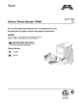
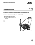
1
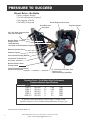
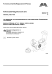
Premium Series
Professional
Pressure Washers
Service/Operation
Manual
Form No. 001-612 APR2605
For Technical Assistance:
Tel: 805-523-0211 Option 3
Email: [email protected]
For Customer Service/Order Desk:
Tel: 805-523-0211 Option 2
Email: [email protected]
Manufactured by: AIRLESSCO BY DUROTECH CO.
P.O. Box 8006, Moorpark, CA 93020-8006 Ship to: 5397 Commerce Ave., Moorpark, CA 93021
Tel: 805-523-0211 Fax: 805-523-1063 SUBJECT TO CHANGE WITHOUT NOTICE.
Copyright © 2005, Airlessco by Durotech. All rights reserved.
TABLE OF CONTENTS
Introduction
Pressure Washer Specifications
Safety Warnings
1
2
Getting Started
Parts
Users Guide
Get The Most From Your Machine
4
5
6
Repairs/Maintenance Instructions
Tips and Nozzles
7
Cleaning Nozzle Rating Chart
8
Troubleshooting
9
Pump Servicing Procedure
10
Application & Installation of
the Unloader Valve
21
Troubleshooting - Unloader Valve
21
Downstream Chemical Injectors
31
Sandblast Kit
32
Sandblasting Application
33
Troubleshooting - Sandblast Kit
33
Limited Warranty
34
Accessories
back cover
Product Diagrams & Parts List
Specifications - Model 1500-3
Dimensional Drawing - Model 1500-3
Parts Breakdown - Model 1500-3
Specifications - Model 2500-3
Dimensional Drawing - Model 2500-3
Parts Breakdown - Model 2500-3
Specifications - Model 2500-5
Dimensional Drawing - Model 2500-5
Parts Breakdown - Model 2500-5
Specifications - Model 3000-4
Dimensional Drawing - Model 3000-4
Parts Breakdown - Model 3000-4
Specifications - Model 4000-3.5
Dimensional Drawing - Model 4000-3.5
Parts Breakdown - Model 4000-3.5
Specifications & Breakdown for
Unloader Valve YVB135KDM
Specifications & Breakdown for
Unloader Valve YVB75KDMN
Frame Assembly Part No. 163-055
Frame Assembly Part No. 163-024
Pump Assembly - Model 1500-3
Pump Assembly - Model 2500-3
Pump Assembly - Model 2500-5
Pump Assembly - Model 3000-4
Pump Assembly - Model 4000-3.5
11
11
12
13
13
14
15
15
16
17
17
18
19
19
20
22
23
24
25
26
27
28
29
30
HANDLE THIS UNIT AS YOU WOULD A LOADED FIREARM!!
High pressure spray can cause extremely serious injury.
OBSERVE ALL WARNINGS!
Before operating this unit, read and follow all safety warnings and instructions
related to the usage of this equipment.
WWW.AIRLESSCO.COM TEL: 805-523-0211 FAX: 805-523-1063
Email: [email protected]
PRESSURE TO SUCCEED
Direct Drive - No Belts
• More compact design
• No belt adjustment required
• No slippage of belts
• No bulky belt guard
Honda Engine with oil alert
Engine Protector
Hose Rack and
Gun Hook
50’ x 3/8” High Pressure Hose
with Quick Couplers
General Pump - Ceramic
Plunger-3 Plex
• Best Warranty
• All easily accessible pump components
Modular Unloader Valve
Chemical Injector
Color Coded Cleaning Nozzles
Convenient Tip Holder on
the Frame
Durable Chrome Steel
Tubular Frame
Thermal Protector and Safety
Pressure Relief Valve
13” Turf Saver Pneumatic Tires
• Easier to roll
• Shock absorbing capability
Premium Series - Cold Water High Performance
Pressure Washers Specifications
HP
GPM
PSI
P.N.
Model
4
2.80
1500
163-060
1500-3
5.5
2.88
2500
163-061
2500-3
11
4.0
3000
163-063
3000-4
11
4.6
3000
163-062
2500-5
11
3.5
4000
4000-3.5 163-064
All pumps come standard with Honda Engine, General Pump,
Chemical Injector, 5 Color Coded Cleaning Nozzles, 50’ hose, gun
*Picture shown is Model 4000-3.5
1
WWW.AIRLESSCO.COM TEL: 805-523-0211 FAX: 805-523-1063
Email: [email protected]
WARNINGS
HIGH PRESSURE SPRAY CAN CAUSE EXTREMELY SERIOUS INJURY.
NEVER PUT YOUR HAND OR FINGERS IN FRONT OF GUN.
NEVER POINT THE GUN AT YOUR BODY OR AT ANYONE ELSE.
• Always shut off the pump and relieve fluid pressure in system by opening control handle if unit is left
unattended or before removing or installing accessories.
NOTE: Shutting off power by itself may not relieve fluid pressure.
• When control handle is not in use, engage trigger safety to prevent accidental spraying.
• Do not allow kinks to form in hose between pump and control handle as this will reduce safety factor.
• Always wear face shield, eye goggles, gloves and protective clothing, so spray containing chemicals do not
contact eyes, ears, nose or skin. If chemicals do contact skin or eyes, flush immediately with large amounts
of water and seek medical attention.
Do not run the engine in
an enclosed area. Exhaust gases
contain carbon monoxide, an odorless
and deadly poison.
Do not run engine at excessive speed.
Excessive speeds increase
the danger of personal injury and
voids warranty.
A FIRE OR EXPLOSION CAN OCCUR RESULTING IN PERSONAL INJURY IF THE
FOLLOWING INSTRUCTIONS ARE NOT FOLLOWED:
• DO NOT FILL GASOLINE TANK while engine is
• Do not operate the engine if air cleaner or cover
• Do not operate the engine when an odor of gasoline is
• Do not choke carburetor to stop engine.
running. Allow engine to cool before refueling.
present or other explosive conditions exist.
• If gasoline is spilled, move machine away from the
area of the spill and avoid creating any source of
ignition until the gasoline has been cleaned up.
• Do not store, spill or use gasoline near an open flame
or devices that utilizes a pilot light or which may
cause a spark such as a stove, furnace or water heater.
• Refuel outdoors or in well ventilated areas only.
• DO NOT operate engine without a muffler. Inspect
muffler periodically and replace as necessary. Clean
muffler area to prevent dirt and combustible material
from accumulating.
directly over the carburetor air intake is removed.
• Do not tamper with the engine speed.
• Do not touch hot muffler, cylinders or fins as contact
may cause burns.
• Dirt or other debris in cooling fins or governor parts,
can affect engine speed.
• To prevent hand or arm injury, always pull starter
cord rapidly to avoid kickback.
• To prevent accidental starting when servicing, always
remove spark plug and insert in holding tab & disconnect negative wire from battery terminal if equipped
with a 12 volt starting system.
• Exhaust fumes are poisonous. Do not operate except
in open and well ventilated areas.
WWW.AIRLESSCO.COM TEL: 805-523-0211 FAX: 805-523-1063
Email: [email protected]
2
WARNINGS
ALWAYS:
• Always remember that liquid released at pressure can penetrate skin, causing SERIOUS injury.
If injury occurs, seek immediate medical attention.
•
•
•
•
•
Always follow all instructions and recommendations when operating equipment.
Always protect high pressure hose from damage such as from vehicle traffic and sharp edges.
Always wear protective clothing, gloves and goggles when using any potentially harmful chemicals.
Always lock gun jet off when removing or changing nozzle.
Always insure nozzle is secure in coupler before using. Improper installation may cause serious
injury or other damage. Test by aiming nozzle at ground prior to use.
• Always insure that water supply is adequate to supply pump. Water supply must deliver 3.5 gallons
per minute.
• Always inspect unit, hoses and fittings prior to use.
NEVER:
•
•
•
•
•
•
Never place hand or any other part of the body in front of spray orifice.
Never direct spray at self or any other person.
Never pump any acid or abrasive fluid.
Never wash electrical equipment or parts.
Never attempt to repair a damaged high-pressure hose.
Never allow unit to run more than five minutes without operating gun jet. Water in pump will
overheat sufficiently to damage pump. An optional high temperature sensor is available for this
unit from Airlessco.
WHILE OPERATING MAINTAIN SUFFICIENT LEVELS OF:
• Fuel - Any fuel intended for automotive use is adequate. Unleaded fuel is recommended to reduce
combustion deposits.
• Engine Oil - See engine manual for checking procedure and recommended oil grade.
• Gearbox Oil - Check through sight window on side of gearbox. Replenish with 90 wt. gear oil.
• Pump Oil - Check through sight window on side of pump. Replenish with SAE 20/ 30 oil.
3
WWW.AIRLESSCO.COM TEL: 805-523-0211 FAX: 805-523-1063
Email: [email protected]
PARTS
INLET WATER FILTER
• The inlet water screen is intended to prevent debris from entering the pump and causing damage. DO NOT
OPERATE the machine without the Inlet Water Screen in place.
• The Inlet Water Screen is stainless steel and should be removed and cleaned every 25 hours of operation. If
your water conditions are poorer than normal, it should be cleaned more often.
HIGH PRESSURE HOSE
• The hose provided by AIRLESSCO is selected from the finest hoses available and is intended to be used on your
machine only.
• DO NOT use pressure hose for any other purpose & do not substitute any other hoses for high pressure hose.
• If the hose becomes frayed or has any cuts on it, the hose must be replaced.
• Do not allow your pressure hoses to be run over by any type of vehicle.
SPRAY GUN- OR CONTROL HANDLE
•
•
•
•
The gun included with your machine should always be treated as a loaded firearm.
HIGH PRESSURE WATER IS DANGEROUS & should never be directed at any person or any body parts.
Your gun has safety features you should use. The Trigger Lock should be engaged any time gun is not in use.
DO NOT TAPE OR TIE, in any way render the spring device inoperative.
WAND
• The wand supplied with your machine should be handled with care. If the wand is bent it should be replaced.
CHEMICAL INJECTOR
• Your machine is equipped to use a CHEMICAL INJECTOR for those jobs that require more than water cleaning.
The AIRLESSCO CHEMICAL INJECTOR will allow you to soak the surface with a liquid chemical/detergent.
• If you need to use surface conditioners such as soaps and degreasers, you must use a CHEMICAL INJECTOR.
• DO NOT pump any surface conditions or any other medium other than water through the high pressure pump.
To do so could damage the pump and void your warranty.
SAND INJECTOR - OPTIONAL ITEM
• AIRLESSCO units are equipped to use a SAND INJECTOR SYSTEM. Water Sandblasting is an extremely
effective way of cleaning. The AIRLESSCO SAND BLASTING INJECTOR allows sand to flow into the high
pressure water stream to create a powerful cleaning system. Dry sandblasting is being replaced by wet
sandblasting. SOME USES: Removing boat barnacles, rust, graffiti and blasting painted surfaces down to metal
for repainting.
WWW.AIRLESSCO.COM TEL: 805-523-0211 FAX: 805-523-1063
Email: [email protected]
4
USERS GUIDE
Prior to Starting:
• Read and understand all warnings before operating euipment.
• Connect standard garden hose to water inlet. Hose must have minimum 5/8 inch diameter. Maximum 50 Ft.
length is recommended. Water source must deliver 3.5 gallons per minute either through pressurized system
of public utility or similar system or through gravity feed from unpressurized holding tank. Never allow
pump to run dry or semi-dry.
• Connect high pressure hose, gunjet, wand assembly to high pressure outlet. Failure to properly lock quick
coupler sleeve may result in “blow-out” and loss of quick coupler O-ring.
• Turn water supply fully on.
• Open fuel valve on engine. Turn ignition switch on (if so equipped). Set choke and throttle controls.
• Operate control handle (gun) by squeezing trigger and hold until continuous flow of water emerges.
• Turn pressure adjustment knob fully counterclockwise.
PREPARATION INSTRUCTIONS BEFORE WASHING OR REPAINTING YOUR HOSE
1. Please read all safety warnings.
2. If walls are badly stained, mildewed or soiled, detergents and the Airlessco Chemical Injector are recommended.
A strong cleanser or tri-sodium phosphate works well to remove stains. Bleaches help to kill mildew.
USING THE AIRLESSCO CHEMICAL INJECTOR
●The chemical injector will draw the detergent. It is adjustable for the required ratio.
●Wash from the BOTTOM to the TOP so the solution is continually being rewetted and
allows the chemical to work.
●Rinse from the TOP to the BOTTOM before the chemical dries.
3. Cover outdoor light and electrical fixtures with plastic bags.
4. Protect flush receptacles with plastic tape. Be sure they are watertight.
5. Note location of vent openings. (Eaves & crawl spaces often have vent openings). Do not spray into these
openings.
6. Protect landscape with plastic covers. This helps in clean up.
(Especially helpful when using chemicals and when blasting off paint).
7. General washing technique is started from the highest point. When working from a ladder make sure it is
sturdy and position the ladder so you are spraying away from yourself. Never spray directly overhead. Be
prepared for the initial “kick” that is caused by the high pressure spray.
8. Start flushing debris out of gutters. Use a 15 degree nozzle about 3 feet away.
9. Wash underhang portion of soffit throughly, spraying from a distance of 12" to 18".
10. When cleaning the sides of your house work from the top to the bottom using overlapping strokes. If using
chemicals or soap apply solution from bottom to top and then rinse from the top to the bottom.
11. When cleaning around windows, approach it cautiously. If panes are not secure or not well caulked they can
break from the impact of the high pressure spray. Use a wider nozzle, start from a distance and approach
cautiously.
5
WWW.AIRLESSCO.COM TEL: 805-523-0211 FAX: 805-523-1063
Email: [email protected]
USERS GUIDE
To Operate Unit:
Chemical Injector:
1. Select desired nozzle. Lock control handle (gun or
wand) off and install nozzle in quick coupler
at end of wand. Insure that coupler sleeve is
properly locked by pulling on nozzle.
2. Start engine according to engine manual.
3. Unlock control handle (gun or wand), point
wand at ground and operate to test.
4. Adjust pressure of spray to desired level.To Use
TO REMOVE PEELING PAINT:
1. Push end of chemical pick-up tube onto injector inlet.
2. Place filter end of pick-up tube in container of chemical
to be dispensed. Unit mixes chemical with water.
Ratio is adjustable.
3. Attach proper nozzle to wand. (Injector will draw
chemical only with special large orifice, fan pattern
nozzle supplied).
4. Operate control handle as usual.
5. After use, remove nozzle from wand and place pick-up
tube filter end in container of water. Flush out tube by
operating gunjet.
1. Start at the highest point. Use a 15 degree nozzle.
2. Spray should be directed 4"-12" from the surface at an angle of 45 degrees. This will allow you to work the
spray like a chisel.
3. On the soffit, peel at a parallel angle. It will peel off in large sheets if you can get beneath it.
4. Spray in a back & forth motion always trying to get beneath the peeling paint. Be sure to get as much paint off as
possible & don’t be concerned about the paint that remains, it is bonded well enough to not cause a problem.
5. If paint edges curl up after being pressure washed, use a scraper or steel brush on these areas.
6. Remove loose putty around windows.
7. Spot prime any bare wood areas. When primer has dried apply putty and caulking as necessary.
GET THE MOST FROM YOUR MACHINE
•
•
•
•
•
Select the right tip for the job.
Never allow anyone into your work area & risk injury.
Approach target from a slight angle (“sweep” surface).
Always wear face shield and eye protection.
Turn machine off and relieve pressure from hose &
system before disconnecting hoses, control handle
(gun) or tips.
• Cover any exposed electrical sockets, plugs, lights or
other exposed electrical connections.
• Do not kink the high pressure hose, the wires inside
may bend and become weak or break.
• Always consider which way the wind is blowing to
avoid overspraying.
• Spray surface conditioners so you are “Up Wind”.
• Never allow surface conditioners, soap or other chemicals to get on vegetation. Use plastic sheeting to protect.
• Keep the quick couplers out of dirt and sand. If they
should have dirt or other debris on them, clean the quick
coupler thoroughly before using.
• Do not allow your hand or body to come in contact with
water spray. HANDLE AS YOU WOULD A LOADED
FIREARM!!
REMEMBER, although prepertion is hard work it will mean extra years of good
protection and good looks.
0º For Power Blasting - Delivers very concentrated stream of water. Exercise caution as the
impact force can damage soft surfaces.
15º For Chiseling & Stripping Action - Quickly removes blistered and peeling paint or other
residues. Spray should be directed at 45° angle.
25° For Power Cleaning & Flushing - The perfect wider spray angle for effectively washing
away dirt, mud and grime.
40º For Moderate Washing & Rinsing - Its wide spray pattern “sweeps” surfaces clean.
WWW.AIRLESSCO.COM TEL: 805-523-0211 FAX: 805-523-1063
Email: [email protected]
6
TIPS AND NOZZLES
TIPS OR NOZZLES
THE 15 DEGREE NOZZLE – 3/4"
The Quick Couplet Tips or Nozzles are inserted into the
end of the wand by means of a Quick Coupler. Tips are
supplied in the four most popular sizes & can do many
jobs for you. You MUST seat the tip into the quick coupler
firmly and make sure the quick coupler is closed. If you
have a leak at the tip around the quick coupler, you have
lost the O-Ring inside the quick coupler. If lost, the O-Ring
MUST BE REPLACED!
This is a chiseling nozzle. The spray should be directed at a
45 degree angle to the surface and used like a scraper to remove paint, grease and dirt. This is the most used tip of all.
Failure to lock the quick coupler into place can result in
personal injury and loss of the O-Ring on a female coupler.
Danger signals are indicated by water leakage.
15°
THE 25 DEGREE NOZZLE – 5-6”
This is a flushing nozzle. It gives a wider coverage and is
used if the area being cleaned would be damaged by a narrower tip.
25°
THE 40 DEGREE NOZZLE – 8-10” –
This is a wash nozzle. Its wide spray pattern disperses the
water pressure over a large area and is recommended
for rinsing and moderate washing.
Learning what each tip can do for you will make your
AIRLESSCO machine more valuable and will allow you
to do your cleaning jobs faster and more effectively. By
experimenting, you will find that different tips do the job
better and moving the wand closer to and farther from the
area to be cleaned will also change the way the machine
will work for you.
You should always start each new job away from the target
and move closer as you see the need. Be careful, you can
damage some surfaces if the pressure is too concentrated
and too close.
NOZZLE SELECTION GUIDE
The pressure and volume of a pressure washer is determined by the size of the opening (orifice) in the nozzle.
There are numbers on the nozzle which explain it’s size.
The first two numbers indicate the size of the spray angle.
(00 means 0 degree, 15 means 15 degrees etc…) The last
number indicates the size of the orifice. This is not a measurement of an inch, but a standardized measurement.
THE 0 DEGREE NOZZLE –
This is the blasting nozzle. It delivers a very concentrated
stream of water. Care should be used to avoid damaging
wood or fragile surfaces. WARNING: This nozzle must
not be used on rental machines supplied to homeowners or
non-contractors.
0°
7
40°
TIPS WILL WEAR IN TIME. THE MORE
YOU USE A TIP, THE MORE YOUR TIP
WILL WEAR. A WORN TIP WILL CAUSE A
SIGNIFICANT DROP IN PRESSURE. CHECK
AND REPLACE YOUR TIPS FREQUENTLY.
QUICK COUPLER
The quick coupler allows you to attach different devices together quick and secure. To use, simply slide the collar back
and insert the plug. Make sure the plug is securely seated.
It’s always a good idea to “tug” on the two parts to make
sure they are firmly seated together.
Socket
Plug
Always make sure the O-Ring is in place inside the quick
coupler. To see if the O-Ring is in place, make sure the Pressure Washer is off and all system pressure has been relieved,
then you may look into the quick coupler at the collar (female) side of the quick coupler. You will be able to see the
O-Ring inside. If the O-Ring is missing, it must be replaced
to ensure a good pressure seal.
WWW.AIRLESSCO.COM TEL: 805-523-0211 FAX: 805-523-1063
Email: [email protected]
CLEANING NOZZLE RATING CHART
The chart below provides gallons per minute for a 0˚ cleaning nozzle used on different PSI (pounds
per square inch) pressure washers. For example, a 2000 PSI pressure washer with a 0˚ No. 4.5 cleaning
nozzle will produce 3.1 gallons per minute. This chart can also assist in determining the proper nozzle
size for a particular pressure washer if the operating pressure and gallons per minute rating are known.
For example: a pressure washer rated at 3000 PSI @ 3.5 GPM, would require a No. 4 cleaning nozzle.
NOTE: The proper nozzle size for each pressure washer
can be found on the machine specification plate (located on the frame).
Nozzle
PSI
Orifice Size 1000 1500 2000 2500 3000 3500 4000 5000
3.0
1.8
2.1
2.4
2.6
2.8
2.8 3.35
4.0
2.0
2.4
2.8
3.1
3.5
3.7
4.0
4.5
4.5
2.2
2.7
3.1
3.5
3.8
4.2
4.5
5.0
5.0
2.5
3.1
3.5
3.9
4.3
4.7
5.0
5.6
5.5
2.8
3.4
3.9
4.3
4.8
5.1
5.5
6.2
6.0
3.0
3.7
4.2
4.7
5.2
5.6
6.0
6.7
6.5
3.3
4.0
4.6
5.1
5.6
6.1
6.5
7.3
7.0
3.5
4.3
4.9
5.5
6.1
6.6
7.0
7.8
7.5
3.8
4.6
5.3
5.9
6.5
7.0
7.5
8.4
8.0
4.0
4.9
5.7
6.3
6.9
7.4
8.0
8.9
8.5
4.3
5.2
6.0
6.7
7.4
8.0
8.5
9.5
9.0
4.5
5.5
6.4
7.1
7.8
8.4
9.0 10.1
WWW.AIRLESSCO.COM TEL: 805-523-0211 FAX: 805-523-1063
Email: [email protected]
8
TROUBLE SHOOTING
PROBLEM
CAUSE
• Worn nozzle
• Air leak in inlet plumbing
• Relief valve stuck, partially
plugged or improperly adjusted
valve seat worn
• Inlet suction strainer clogged or
improperly sized
Low Pressure
• Worn packing; Abrasives in
pumped fluid or severe cavitation;
Inadequate water
• Fouled or dirty inlet or discharge
valves. Leaky discharge hose
• Install proper filter, suction at manifold
must be limited to lifting less than 20
feet of water or -8.5 PSI vacuum.
• Clean inlet and discharge valve assemblies
• Replace worn valves, valve seats and/
or discharge hose
Pump runs extremely
rough, pressure very
low
• Restricted inlet or air entering the
inlet plumbing
• Inlet restrictions and/or air leaks;
Stuck inlet or discharge valve
• Proper size inlet plumbing; check for air
tight seal.
• Replace worn cup or cups; clean out
foreign material, replace worn valve
Water leakage from
under manifold; Slight
leakage
• Worn packing
• Install new packing
Oil leak between
crankcase and
pumping section
• Worn crankcase, piston rod
seals O-ring on plunger
• Replace crankcase piston rod seals;
Replace O-rings
Oil leaking in the area
of crankshaft
• Worn crankshaft seal or improperly
installed oil seal O-ring
• Bad bearing
• Remove oil seal and replace damaged
O-ring and/ or seals
• Replace bearing
Excessive play in the
end of the crankshaft
pulley
• Worn main bearing form
excessive tension on drive belt
• Replace crankcase bearing and/or tension
drive belt
• May be caused by humid air
condensing into water inside the
crankcase
• Worn packing and/or piston rod
sleeve, & O-rings on plunger retainer
• Change oil intervals; use any high grade
automotive 30 weight non detergent oil
Oil leaking from underside of crankcase
• Worn crankcase piston rod seals
• Replace seals
Oil leaking at the rear
portion of the
crankcase
• Damaged crankcase, rear cover
O-ring, drain plug O-ring or slight
glass O-ring
• Replace specific O-ring
Loud knocking noise
in pump
• Pulley loose on crankshaft
• Broken or worn bearing
• Check key and tighten set screw
• Replace bearing
Frequent or premature
failure of the packing
• Scored, damaged or worn plunger
• Overpressure to inlet manifold
• Abrasive material in the fluid being
pumped
• Excessive pressure and/or
temperature of fluid being pumped
• Over pressure of pumps
• Running pump dry
• Replace plungers
• Reduce inlet pressure
• Install proper filtration on pump inlet
plumbing
• Check pressure and fluid inlet temperature;
be sure they are with in specified range.
• Reduce pressure
• Do not run pump without water
Water in crankcase
9
REMEDY
• Disassemble, reseal and reassemble
• Clean, adjust relief valve; check for
worn and dirty valve seats
• Clean, use adequate size; check more
frequently
• Replace packing, replace O-rings
WWW.AIRLESSCO.COM TEL: 805-523-0211 FAX: 805-523-1063
Email: [email protected]
PUMP SERVICING PROCEDURE
Replacing Plungers
Valve Assemblies
1. All inlet and discharge valves can be serviced without 1. Remove stainless steel piston screw and plunger
from piston.
disrupting the inlet discharge plumbing. The inlet and
discharge valves are the identical in all models.
2. If slinger washer comes off with plunger, be certain
this is replaced before new plunger is installed.
2. To service any valve, remove valve cap and extract
valve assembly.
3. Separate piston screw from plunger.
3. Examine O-rings and replace if there is any evidence
of cuts, abrasions, or distortion.
4. Remove valve assembly (retainer, spring, valve,
valve seat) from valve cavity.
5. Remove O-ring from valve cavity.
6. Only one valve kit is necessary to repair all the valves
in the pump. The kit includes new O-rings, valve
seat, poppet, spring and retainer, all pre-assembled.
7. Install new O-ring in valve cavity.
4. Install new O-Ring and teflon backup-ring on piston
screw. Note: A film of grease on the outside of the
O-Rings insures a better installation.
5. Carefully press piston screw into plunger.
6. Slide new plunger over the piston guide and torque
to specifications.
Replacing V-Packings
1. Remove manifold from crankcase.
8. Insert assembly into valve cavity.
9. Replace valve cap and torque to specifications.
2. Insert proper extractor collet through main seal
retainer. Tighten collet and extract retainers,
v-packings and head rings.
Removing Manifold Head
3. Place proper insertion tool in cylinder and install
front head ring, v-packing and long life ring and
press firmly into cylinder untill they will go no
further using proper insertion tool.
1. Remove the fasteners retaining head.
2. Separate head from crankcase.
Note: It may be neccessary to tap the head lightly
with a rawhide mallet to loosen.
When sliding head from crankcase use
caution not to damage plungers.
3. The V-packing assemblies may come off with the
head. At this point, examine plungers. Plunger
surfaces should be smooth and free from scoring or
pitting; if not, replace.
4. Reinstall manifold head and torque to specifications
per sequence described below.
4. Insert intermediate seal retainer, pressing it firmly
into cylinder untill it will go no further using proper
insertion tool. Install rear head ring, v-packing and
main seal retainer into cylinder in order shown and
press firmly into cylinder.
5. Repeat this sequence for each cylinder.
6. Coat each plunger with grease and carefully
remount manifold. Torque head to specifications.
Torque Sequence For Tightening Head
Install all head bolts finger tight. Torque to 10 foot
pounds in sequence as shown below, then retorque to
specifications again in sequence.
WWW.AIRLESSCO.COM TEL: 805-523-0211 FAX: 805-523-1063
Email: [email protected]
10
SPECIFICATIONS - MODEL 1500-3
PART NUMBER 163-060
Specifications
Pump Model
Maximum Volume
Maximum Discharge Pressure
Maximum Pump Speed
Maximum Inlet Pressure
Maximum Inlet Vacuum
Bore
Stroke (in./mm)
Crankcase Oil Capacity
Maximum Fluid Temperature
Inlet Port Thread
Discharge Port Thread
Shaft Diameter
Weight
Dimensions
1500-3
2.8 GPM
1500 PSI
3400 RPM
125 PSI
3 ft. water (2.6 in. Hg)
.591 in./ 15mm
.260/ 6.6
11.2 oz.
165˚F
3/8 -19 BSPP-F
1/4 - 19 BSPP-F
3/4 in. / 19 mm
11.4 lbs.
7.2 x 7.2 x 5.5 in.
TORQUE SPECS*
Position
2
6
9
16
Ft. - lbs.
29.4
14.7
8.8
33.1
Position
23
26
34
Ft. - lbs.
13.2
11.0
7.3
*Decrease torque by 20% if
threads are lubricated.
*For Position Number Reference Parts Breakdown Page 12.
MODEL 1500-3 DIMENSIONAL DRAWING
11
WWW.AIRLESSCO.COM TEL: 805-523-0211 FAX: 805-523-1063
Email: [email protected]
PARTS BREAKDOWN - MODEL 1500-3
PART NUMBER 163-060
ITEM
PART #
DESCRIPTION
QTY.
ITEM
PART #
DESCRIPTION
1
51.0106.22
Crankcase
KIT
1
26
92.2216.00
Nut, M8
3
2
98.2100.00
Plug, 3/8-BSPP
2
27
96.7008.00
Washer, M8
3
3
90.3833.00
O-Ring, .549 x .103
1
28
51.0400.09
Plunger (15mm)
3
4
51.2091.02
Protector
1
29
90.3572.00
O-Ring, .208 x .070
3
5
90.1565.00
Oil Seal
3
30
90.5022.00
Back-up Ring
3
6
98.2041.00
Plug
1
31
96.7070.00
Washer, Flinger
3
7
51.1200.41
Manifold, Brass
1
32
97.7310.00
Connecting Rod Pin
3
51.1200.22
Manifold, Aluminum
33
51.1600.22
Crankcase Cover
1
8
96.6938.00
Washer, M6.4, Schnorr
12
34
99.1867.00
Screw
4
9
99.1943.00
Screw, M6 x 40
12
35
90.3917.00
O-Ring
1
10
90.3841.00
O-Ring, .674 x .103
1
6
36
51.0300.22
Connecting Rod
3
11
36.2003.66
Valve Seat
1
6
12
36.2001.76
Valve Plate
1
6
37
61.0500.56
Piston Guide
3
13
94.7376.00
Spring
1
6
60
99.2730.00
Screw, 5/16”
4
14
36.2002.51
Valve Cage
1
6
61
96.7014.00
Washer, M8.4, Schnorr
4
15
90.3847.00
O-Ring, .797 x .103
84
6
62
10.0346.22
Flange
1
16
98.2218.00
Valve Cap
84
6
63
99.1867.00
Screw, M6 x 18
4
17
36.7032.01
Valve Assembly
1
6
64
96.6938.00
Washer, M6.4, Schnorr
4
18
51.100.51
Head Ring
96,97
3
65
50.2115.51
Spacer
1
19
90.2620.00
Packing
96,97
3
66
90.4097.00
O-Ring, 2.187 x .139
1
20
51.0800.70
Packing Retainer
86,96
3
67
90.1644.00
Oil Seal
1
21
90.3604.00
O-Ring, .989 x .070
86,96,97
3
68
90.0667.00
Snap Ring
1
22
90.3835.00
O-Ring, .594 x .103
86,96,97
3
69
20.2835.21
Bearing
1
23
97.5968.00
Slight Gauge
1
70
51.0211.35
Crankshaft
1
24
91.8015.00
Needle Bearing
1
25
98.2103.00
Oil Dip Stick
1
83
KIT
QTY.
REPAIR KITS
KIT NO.
1
ITEM NO.S
10, 11, 12
INCLUDED
6, 7, 8
IN KIT
(17)
NUMBER OF
6
ASSEMBLIES
IN KIT
NUMBER OF
3
CYLINDERS KIT
WILL SERVICE
83
5
84
15, 16
86
20, 21,
22
97
18, 19,
21, 22
3
96
18, 19,
20, 21,
22
1
3
6
3
3
3
1
3
WWW.AIRLESSCO.COM TEL: 805-523-0211 FAX: 805-523-1063
Email: [email protected]
3
12
SPECIFICATIONS - MODEL 2500-3
PART NUMBER 163-061
Specifications
Pump Model
Maximum Volume
Maximum Discharge Pressure
Maximum Pump Speed
Maximum Inlet Pressure
Maximum Inlet Vacuum
Bore
Stroke (in./mm)
Crankcase Oil Capacity
Maximum Fluid Temperature
Inlet Port Thread
Discharge Port Thread
Shaft Diameter
Weight
Dimensions
Position
2
6
9
16
2500-3
3.2 GPM
2500 PSI
3400 RPM
125 PSI
3 ft. water (2.6 in. Hg)
.709 in./ 18 mm
.370 in./ 9.4 mm
11.2 oz.
165˚F
3/8 -19 BSPP-F
1/4 - 19 BSPP-F
.945 in./ 24 mm
11.2 lbs.
7.0 x 6.9 x 5.1 in.
TORQUE SPECS*
Ft. - lbs.
Position
29.4
23
14.7
26
8.8
34
33.1
39
Ft. - lbs.
13.2
11.0
7.3
7.3
*Decrease torque by 20% if threads are lubricated.
*For Position Number Reference Parts Breakdown Page 14.
MODEL 2500-3 DIMENSIONAL DRAWING
13
WWW.AIRLESSCO.COM TEL: 805-523-0211 FAX: 805-523-1063
Email: [email protected]
PARTS BREAKDOWN - MODEL 2500-3
PART NUMBER 163-061
ITEM
ITEM
NO.
PART
#
PART
NO.
QTY.
OTY.
ITEM
PART #
DESCRIPTION
KIT #
1
51.0106.22
Crankcase
1
20
51.0800.70
Packing Retainer
86,96
2
98.2100.00
Plug
2
51.0803.70
18mm
139,140
3
90.3833.00
O-Ring
1
90.3604.00
O-Ring
86,96,97
4
51.2091.02
Protector
1
18mm
139,140,141
5
90.1565.00
Oil Seal
6
98.2041.00
Plug
1
7
51.12200.41
Manifold, Brass
1
23
97.5968.00
Slight Gauge
1
8
96.6938.00
Washer
8
24
91.8015.00
Needle Bearing
1
9
99.1943.00
Screw
8
25
98.21103.00
Oil Dip Stick
1
10
90.3841.00
O-Ring
123
6
26
92.2216.00
Nut
3
11
36.2003.66
Valve Seat
123
6
27
96.7008.00
Washer
3
12
36.2001.76
Valve Plate
123
6
28
51.0400.09
Plunger - 15mm
3
13
94.7376.00
Spring
123
6
51.0401.66
Plunger - 18mm
14
36.2025.51
Valve Cage
123
6
29
90.3572.00
O-Ring
3
15
90.3847.00
O-Ring
6
30
90.5022.00
Back Up Ring
3
16
98.2216.00
Valve Cap
6
17
36.7115.01
Valve Assembly
123
6
31
96.7070.00
Flinger Washer
3
18
51.1000.51
Head Ring
96,97
3
32
97.7310.00
Connecting Rod Pin
3
51.1001.51
18mm
140,141
33
51.1600.22
Crankcase Cover
1
90.2620.00
Packing
96,97
34
99.1867.00
Screw
4
90.2681.00
18mm
140,141
35
90.3917.00
Cover O-Ring
1
19
DESCRIPTION
DESCRIPTION
KITNO.
#
KIT
83
21
22
3
3
90.3835.00
O-Ring
86,96,97
90.3843.00
18mm
139,140,141
QTY.
3
3
3
REPAIR KITS
KIT NUMBER
83
ITEM NO.S
INCLUDED
IN KIT
NUMBER OF
ASSEMBLIES
IN KIT
NUMBER OF
CYLINDERS KIT
86
96
97
(15mm)
(15mm)
(15mm)
5
20,21
22
18,19
21,22
3
3
18,19
20,21,
22
1
3
3
1
123
139
140
141
(18mm)
(18mm)
(18mm)
20,21
22
3
18,19
20,21
22
1
18,19
21,22
3
6,7,8
10,11,12
(17)
6
3
3
3
1
3
WWW.AIRLESSCO.COM TEL: 805-523-0211 FAX: 805-523-1063
Email: [email protected]
3
14
SPECIFICATIONS - MODEL 2500-5
PART NUMBER 163-062
Specifications
Pump Model
Maximum Volume
MaximumDischarge Pressure
Maximum Pump Speed
Maximum Inlet Pressure
Maximum Inlet Vacuum
Bore
Stroke (in./mm)
Crankcase Oil Capacity
Maximum Fluid Temperature
Inlet Port Thread
Discharge Port Thread
Shaft Diameter
Weight
Dimensions
2500-5
4.6 GPM
3000 PSI
3400 RPM
125 PSI
3 ft. water (2.6 in. Hg)
.591 in./ 15 mm
.433/ 11
14.0 oz.
165˚F
1/2-14 BSPP-F
3/8-19 BSPP-F
1.0 in./ 25.4 mm
19.1 lbs.
8.8 x 9.7 x 6.5 in.
TORQUE SPECS*
Position
2
10
12
26
Ft. - lbs.
14.7
73.7
7.3
7.3
N-M
20
100
10
10
Position
28
35
46
47
Ft. - lbs.
14.7
11.0
29.4
29.4
N-M
20
15
40
40
Position
50
79
84
Ft. - lbs
9.6
14.7
7.3
N-M
13
20
10
*Decrease torque by 20% if threads
are lubricated.
*For Position Number Reference Parts Breakdown Page 16.
MODEL 2500-5 DIMENSIONAL DRAWING
15
WWW.AIRLESSCO.COM TEL: 805-523-0211 FAX: 805-523-1063
Email: [email protected]
PARTS BREAKDOWN - MODEL 2500-5
PART NUMBER 163-062
ITEM
ITEM
PART NO.
PART #
DESCRIPTION
QTY.
ITEM
PART #
DESCRIPTION
1
44.1200.41
Manifold (15mm)
1
30
96.7350.00
Washer
3
2
99.3175.00
Screw
8
31
90.5022.00
Anti-Extrusion Ring
3
3
96.7014.00
Washer
8
32
90.3572.00
O-Ring
3
4
90.3841.00
O-Ring
123
6
33
52.0400.09
Plunger, 15mm
3
5
36.2003.66
Valve Seat
123
6
34
96.7008.00
Washer
3
6
36.2001.76
Valve
123
6
35
92.2216.00
Nut
7
94.7376.00
Spring
123
6
40
90.3612.00
O-Ring
125,130
3
8
36.2025.51
Valve Cage
123
6
41
44.0800.70
Packing Retainer
125,130
3
9
90.3847.00
O-Ring
124
6
42
52.2166.70
Intermediate Ring
89,130
3
10
98.2226.00
Cap Screw
124
6
43
90.2622.00
Packing
88,130
3
11
36.7115.01
Valve Assembly
123
6
44
90.2620.00
Packing
88,130
3
12
99.1807.00
Screw
4
45
51.1000.51
Head Ring
90,130
3
13
50.1500.74
Bearing Cover
1
46
98.2100.00
Cap Screw
1
14
44.2118.01
Spacer
1
47
98.2176.00
Cap Screw
1
15
90.4097.00
O-Ring
1
48
96.7380.00
Washer
1
16
91.8328.00
Ball Bearing
1
49
96.7514.00
Washer
1
17
90.1614.00
Oil Seal
3
50
98.1966.00
Cap Screw
18
44.0100.22
Crankcase
1
51
90.2617.00
Seal, Low Pressure
19
98.2103.00
Oil Dip Stick
1
75
90.0635.00
Retaining Ring
1
22
44.0500.66
Plunger Guide
3
76
44.0212.65
Crankshaft
1
23
44.0300.22
Connecting Rod
3
77
91.8568.00
Roller Bearing
1
24
90.3920.00
O-Ring
1
78
90.4097.00
O-Ring
1
25
44.1600.22
Rear Cover
1
79
99.2755.00
Screw, 5/16” x 1
4
26
99.1837.00
Screw
5
99.3345.00
Screw, 3/8” x 1
4
27
90.3585.00
O-Ring
1
96.7020.00
Washer, 08 mm
4
28
98.2041.00
Cap Screw
1
96.7104.00
Washer, 010 mm
4
29
97.7340.00
Pin
3
10.0518.22
Gas Flange
1
DESCRIPTION
KIT #
KIT NO.
QTY.
23
80
81
KIT #
QTY.
3
1
88,130
3
REPAIR KITS
KIT NUMBER
23
88
89
90
123
124
125
130
ITEM NO.S
INCLUDED
IN KIT
NUMBER OF
ASSEMBLIES
IN KIT
NUMBER OF
CYLINDERS KIT
WILL SERVICE
17
43,44,
51
42
45
9,10
40,41
3
3/6
3
6
4,5,6
7,8,
(11)
6
6
3
40,41,42
43,44,45,
51
1
3
3
3
3
3
3
3
1
WWW.AIRLESSCO.COM TEL: 805-523-0211 FAX: 805-523-1063
Email: [email protected]
16
SPECIFICATIONS - MODEL 3000-4
PART NUMBER 163-063
Specifications
Pump Model
Maximum Volume
MaximumDischarge Pressure
Horsepower
Maximum Pump Speed
Maximum Inlet Pressure
Maximum Inlet Vacuum
Bore
Stroke (in./mm)
Crankcase Oil Capacity
Maximum Fluid Temperature
Inlet Port Thread
Discharge Port Thread
Shaft Diameter
Weight
Dimensions
3000-4
4.0 GPM
3000 PSI
12.3 GBHP
3400 RPM
125 PSI
Flooded
.591 in./15 mm
.394 in./10mm
14.0 oz.
165˚F
1/2-14 BSPP-F
3/8-19 BSPP-F
1.0 in./ 25.4 mm
18 lbs.
8.4 x 8.4 x 6.5 in.
TORQUE SPECS*
Position
2
10
12
26
Ft. - lbs.
14.7
73.7
7.3
7.3
N-M
20
100
10
10
Position
28
35
46
47
Ft. - lbs.
14.7
11.0
29.4
29.4
N-M
20
15
40
40
Position
83
88
Ft. - lbs
14.7
7.3
N-M
20
10
*Decrease torque by 20% if threads
are lubricated.
*For Position Number Reference Parts Breakdown Page 18.
MODEL 3000-4 DIMENSIONAL DRAWING
17
WWW.AIRLESSCO.COM TEL: 805-523-0211 FAX: 805-523-1063
Email: [email protected]
PARTS BREAKDOWN - MODEL 3000-4
PART NUMBER 163-063
ITEM
ITEM
PART #
DESCRIPTION
1
63120041
Manifold, 15 mm
1
31
660024
Anti-extrusion Ring
3
2
99319200
Screw, M8 x 65
8
32
701009
O-ring
3
3
96701400
Lockwasher, M8.4
8
33
52040009
Ceramic Plunger, 15 mm
3
4
90384100
O-ring
123
6
34
44211570
Bushing
3
5
36200366
Valve Seat
123
6
35
92221500
Nut, M8
6
36200176
Valve Plate
123
6
40
63080070
Seal Retn’r, 15 mm
162,166
3
7
94737600
Spring
123
6
41
90360800
O-ring
166,167
3
8
3620551
Valve Cage
123
6
42
90260800
Seal, LP, 15 mm
160,166
3
9
90384700
O-ring
124
6
43
63216070
Int. Ring, 15 mm
164,166
3
10
98222600
Valve Cap
124
6
44
90261200
Packing Ass’y, 15 mm
160,166
3
11
36711501
Valve Assembly
123
6
45
98210000
Plug, 3/8” G
1
12
99180700
Screw, M6 x 10
8
46
98217600
Plug, 1/2” G
1
13
50150074
Bearing Cover
1
47
96738000
Washer, M17.5
1
14
44211801
Oil Level Indicator
1
48
96751400
Washer, M21.5
1
15
90409700
O-ring
2
49
63210051
Oil Level Indicator
1
16
91832900
Ball Bearing
1
50
90405100
O-ring
1
17
90159500
Oil Seal
3
79
90063500
Retaining Ring
1
18
63010022
Crankcase
1
80
63027765
Crankshaft, 6.5
1
19
98210300
Oil Dip Stick
1
63028065
Crankshaft, 8
1
22
63050066
Plunger Guide
3
63028465
Crankshaft, 10
1
23
63030022
Connecting Rod
3
81
99179000
Screw, M6 x 6
1
24
90392000
O-ring, Cover
1
82
91856800
Roller Bearing
1
25
63160022
Rear Crankcase Cover
1
83
99334500
Screw, 3/8 x 1”
4
26
99183700
Screw, M6 x 14
4
84
96710400
Washer
4
27
701013
O-ring
1
85
10051822
Flange 1”, gas engine
1
28
98204100
Plug, 1/4” G
2
86
90169000
Oil Seal
1
29
97733500
Connecting Rod Pin
3
87
96693800
Washer
4
30
96707500
Flinger Washer
3
88
99191200
Screw, M6 x 30
4
ITEM
PART #
RT NO.
DESCRIPTION
DESCRIPTION
KIT #
KIT NO.
159
QTY.
QTY.
KIT #
QTY.
3
REPAIR KITS
KIT NUMBER
123
124
159
160
162
164
166
ITEM NO.S
INCLUDED
IN KIT
NUMBER OF
ASSEMBLIES
IN KIT
NUMBER OF
CYLINDERS KIT
WILL SERVICE
4,5,
6,7,8
(11)
6
9,10
17
42,44
40
43
40,41,42
43,44
6
3
3
3
3
1
3
3
3
3
3
3
1
WWW.AIRLESSCO.COM TEL: 805-523-0211 FAX: 805-523-1063
Email: [email protected]
18
SPECIFICATIONS - MODEL 4000-3.5
PART NUMBER 163-064
Specifications
Pump Model
Maximum Volume
MaximumDischarge Pressure
Maximum Pump Speed
Maximum Inlet Pressure
Maximum Inlet Vacuum
Bore
Stroke (in./mm)
Crankcase Oil Capacity
Maximum Fluid Temperature
Inlet Port Thread
Discharge Port Thread
Shaft Diameter
Weight
Dimensions
4000-3.5
3.5 GPM
4000 PSI
3400 RPM
125 PSI
Flooded
.512 in./13 mm
.433 in./11 mm
14.0 oz.
165˚F
1/2-14 BSPP-F
3/8-19 BSPP-F
1.0 in./ 25.4 mm
20 lbs.
8.8 x 9.7 x 6.5 in.
TORQUE SPECS*
Position
2
10
12
26
Ft. - lbs.
14.7
73.7
7.3
7.3
N-M
20
100
10
10
Position
28
33
46
47
Ft. - lbs.
14.7
6.6
29.4
29.4
N-M
20
9
40
40
Position
50
79
84
Ft. - lbs
9.6
14.7
7.3
N-M
13
20
10
*Decrease torque by 20% if threads
are lubricated.
*For Position Number Reference Parts Breakdown Page 20.
MODEL 4000-3.5 DIMENSIONAL DRAWING
19
WWW.AIRLESSCO.COM TEL: 805-523-0211 FAX: 805-523-1063
Email: [email protected]
PARTS BREAKDOWN - MODEL 4000-3.5
PART NUMBER 163-064
ITEM
PART #
DESCRIPTION
QTY.
ITEM
PART #
DESCRIPTION
1
44120641
Manifold
KIT #
1
30
96696700
Washer
2
99317500
Screw
8
33
44040266
Plunger, 13 mm
3
96701400
Washer
8
40
90361200
O-Ring
152,156
3
4
90384100
O-Ring
123
6
41
44080370
Packing Retainer
152,156
3
5
36200366
Valve Seat
123
6
42
44216270
Intermediate Ring
154,156
3
6
36200176
Valve
123
6
43
90507600
Packing
153,156
3
7
94737600
Spring
123
6
44
90260200
Packing
153,156
3
8
36202551
Valve Cage
123
6
45
44100251
Head Ring
155,156
3
9
90384700
O-Ring
124
6
46
98210000
Cap Screw
1
10
98222600
Cap Screw
124
6
47
98217600
Cap Screw
1
11
36711501
Valve Assembly
123
6
48
96738000
Washer
1
12
99180700
Screw
4
49
96751400
Washer
1
13
50150074
Bearing Cover
1
50
98196600
Cap Screw
14
44211801
Spacer
1
51
90260300
Seal, Low Pressure
15
90409700
O-Ring
1
75
90063500
Retaining Ring
1
16
91832800
Ball Bearing
1
76
44021265
Crankshaft
1
17
90161400
Oil Seal
3
77
91856800
Roller Bearing
1
18
44010022
Crankcase
1
78
90409700
O-Ring
1
19
98210300
Oil Dip Stick
1
79
99275500
Screw, 5/16 x 1
4
22
44050166
Piston Guide
3
99334500
Screw, 3/8 x 1
4
23
44030022
Connecting Rod
3
96702000
Washer, 08 mm
4
24
90392000
O-Ring
1
96710400
Washer, 010 mm
4
25
44160022
Rear Cover
1
81
10051822
Gas Flange
1
26
99183700
Screw
5
82
90169000
Oil Seal
1
27
90358500
O-Ring
1
83
96693800
Washer
4
28
98204100
Cap Screw
1
84
99191200
Screw
4
29
97734000
Pin
3
23
80
KIT #
QTY.
3
3
1
153,156
3
REPAIR KITS
KIT NUMBER
23
123
124
152
153
154
156
ITEM NO.S
INCLUDED
IN KIT
NUMBER OF
ASSEMBLIES
IN KIT
NUMBER OF
CYLINDERS KIT
WILL SERVICE
17
4,5,
6,7,8,
(11)
6
9,10
40,41
43,44,
51
42
3
3
3
6
3
3
3
40,41,42,
43,44,45,
51
1
3
3
3
3
1
WWW.AIRLESSCO.COM TEL: 805-523-0211 FAX: 805-523-1063
Email: [email protected]
20
APPLICATION & INSTALLATION OF THE
UNLOADER VALVE
APPLICATION
This product is to be used with clean, fresh water. For different or corrosive liquids, contact the
Technical Support Department. With not-clean liquids, appropriate filtration should be installed.
Select the valve based on the nominal operating rating: system rated pressure, maximum flow and
maximum temperature.
Under no circumstances should the pressure of the system exceed the maximum rated pressure of
any component. When installed on hot water cleaners, this valve is to be installed before the boiler.
INSTALLATION
On a system that produces hot water, consider installing safety devices which limit the accidental
increase of the fluid temperature. Always install a safety valve to protect the operator and system.
Choose a correct nozzle size, able to discharge regularly, on bypass, at least 5% of the total flow
of the system, in order to achieve a constant pressure and avoid troublesome pressure spikes.
When the nozzle wears, the pressure drops. After installing a new nozzle, re-adjust the system to
the original pressure setting.
TROUBLESHOOTING UNLOADER VALVE
21
PROBLEM
CAUSES
SOLUTION
Unloader cycles
•Damaged seat or cone
•Fitting Leaking
•Restricted bypass
•Replace
•Check and renew
•Clean or adapt
Unloader does not
come up to pressure
•Unloader not properly sized
•Foreign materials between
seat and shutter
•Piston O-Ring worn out
•Nozzle worn out
•Select proper spring or new unloader
•Clean the seat
Pressure peaks
•Spring totally compressed
•Excessive flow in bypass
•There is not a min. 5% of
total flow in bypass
•Loosen and change nozzle size
•Select another unloader
•Adjust size of piping
Unloader does not
bypass at low pressure
•Check valve jammed
•Check valve O-Ring worn out
•Foreign materials on valve
•Clean or replace
•Replace
•Clean
Chemical Injector does
not draw solution
•Foreign matter in chemical hose
•Foreign matter in check valve
•Insufficient pressure drop
across injector
•Clean
•Clean
•Put system in low pressure mode
•Shorten discharge hose
•Check spray tip
•Replace
•Replace
WWW.AIRLESSCO.COM TEL: 805-523-0211 FAX: 805-523-1063
Email: [email protected]
UNLOADER VALVE FOR MODELS:
1500-3 & 2500-3
Specifications
Part Number
YVB135KDM
Maximum Volume
6.5 GPM
Rated Discharge Pressure
2300 PSI
Maximum Discharge Pressure 3400 RPM
Maximum Temperature
195° F
Port Size Inlet
3/8" BSPP-F
Port Size Outlet
3/8" BSPP-M
Dimensions
5.75 x 3.0 x 1.75 in.
Weight
1.4 lb.
Material
Brass, Stainless Steel Plastic, Buna-N
PARTS BREAKDOWN FOR YVB135KDM
Item
Part #
1
Y60.0385.31
Banjo Bolt 1/4” BSPP, Brass
Description
1
2
Y14.4100.00
Washer, 3/8” BSPP, Steel With Rubber Insert
3
3
Y60.0801.35
Housing, Brass
4
Y10.4006.00
Back-Up Ring, 8.6 mm x 6 mm
*
1
5
Y10.3051.01
O-Ring, 70 Duro, Buna-N, .239” ID x .070” CS
*
1
6
Y10.3066.00
O-Ring, 70 Duro, Buna-N, .614” ID x .070” CS
*
3
7
Y60.0303.31
Piston Housing
8
Y60.0319.31
Lock Nut, M18 x 1
9
Y10.3055.00
O-Ring, 70 Duro, Buna-N, .301” ID x .070” CS
*
1
10
Y10.4008.00
Backup Ring, 11 mm x 8 mm
*
1
11
Y60.0331.51
Piston M5, Stainless Steel
*
1
12
Y60.0310.61
Spring Seat
1
13
Y60.0313.61
Spring , White
1
14
Y60.0304.31
Knob, Brass
1
15
Y60.0315.84
Adjustment Knob, Plastic
1
16
Y16.2100.00
Set Screw
1
17
Y14.3813.22
Washer, Aluminum, 13 mm x 22 mm
18
Y10.3125.00
O-Ring, 70 Duro, Buna-N, .157” ID x .098” CS
19
Y60.0308.31
Check Valve
20
Y60.0312.51
Spring, Stainless Steel, Check Valve
21
Y60.0333.21
Ball & Housing M5
*
1
22
Y60.0311.51
Seat, 12 mm x 7 mm
*
1
23
Y10.3005.00
O-Ring, 70 Duro, Buna-N, .394” ID x .039” CS
*
1
24
Y60.0382.31
Bypass Fitting
1
25
Y10.3109.96
O-Ring, 70 Duro, Viton, .406” ID x .094” CS
1
26
Y60.0821.35
Manifold, Brass
1
27
Y60.0803.31
Banjo Bolt 3/8” BSPP, Brass
1
28
Y60.0305.31
Outlet Fitting, 3/8” BSPP-M
*
Y60.0398.24
Repair Kit
WWW.AIRLESSCO.COM TEL: 805-523-0211 FAX: 805-523-1063
Email: [email protected]
Kit Qty
1
1
1
1
*
1
1
1
22
UNLOADER VALVE FOR MODELS:
2500-5 & 3000-4
Specifications
Part Number
YVB75KDMN
Maximum Volume
8.0 GPM
Rated Discharge Pressure
3200 PSI
Maximum Discharge Pressure 3650 RPM
Maximum Temperature
195° F
Port Size Inlet
1/2" BSPP-F
Port Size Outlet
3/8" BSPP-M
Dimensions
6.25 x 4.5 x 1.0 in.
Weight
2.0 lb.
Material
Brass, Stainless Steel Plastic, Buna-N
PARTS BREAKDOWN FOR YVB75KDMN
23
Item
Part #
1
Y60005831
Outlet Fitting, 3/8 BSP
Description
Qty.
1
2
Y10307002
O-Ring, .739 x .070
2
3
Y60005351
SS Spring, .453 x .028
1
4
Y60005231
Hex Check Valve
1
5
Y14410100
Gasket 1/2” BSP
2
6
Y60078335
Manifold, 1/2” BSPP-F
1
7
Y60100831
Hollow Screw, 1/2”, Zinc
1
8
Y60093131
Seat Holder, L 16 mm
1
9
Y10310996
O-Ring, .406 x .095 Viton
1
10
Y60078435
Brass Valve Body
1
11
Y60025920
SS Seat, 8.5 mm
1
12
Y60170821
SS Shutter M6
1
13
Y60100731
Hollow Screw, 3/8” BSPP
1
14
Y14410000
Gasket, 3/8” BS
2
16
Y10306801
O-Ring, .676 x .070
1
17
Y60070831
Piston Housing
1
18
Y16210000
Set Screw, M4 x 4
1
19
Y60101831
Ring Nut, M18 x 1
1
20
Y60070451
SS Piston
1
21
Y10316900
O-Ring, .237 x .104
2
22
Y10402300
Backup Ring, .433 x .251
1
23
Y10321300
O-Ring, .237 x .119
1
24
Y10402400
Backup Ring, .451 x .276
1
25
Y60031061
Spring Seat, Zinc Plated
1
26
Y60031361
White Spring
1
27
Y60030431
Brass Cap
1
28
Y60031584
Plastic Knob
1
WWW.AIRLESSCO.COM TEL: 805-523-0211 FAX: 805-523-1063
Email: [email protected]
FRAME ASSEMBLY PART NO. 163-055
PART
# #
PART
100-317
DESCRIPTION
DESCRIPTION
Nut, 5/16-18” Centerlock
113-031
Spacer, 5/8 ID x 1.0”
188-367
Axel 5/8 x 21.81" Long
143-029
Set Collar 5/8” ID
163-008A
Rubber Foot
163-011A
Washer, 1.25 x .312”
169-050
Screw, 5/16-18 x 1.00 HX HD
171-020
Grommet 9307K25 McMaster
188-042
Nut, 1/4”-20 NY-LOCK
188-185
Spacer, .25 x .088W x .55”
301-165
Wheel, 13 x 500-6 Tubeless
301-510
Frame Weldment, LB/PW
305-088
Screw, 1/4”-20 x 2” SC HD
*Note: For smaller frame part numbers Please call Airlessco's
Technical Service at 805-523-0211 ext. 1751.
WWW.AIRLESSCO.COM TEL: 805-523-0211 FAX: 805-523-1063
Email: [email protected]
24
PUMP ASSEMBLY - PRESSURE WASHER
MODEL 1500-3
NOTES:
1
r
2
r
3
r
4
r
5
r
6.
TORQUE TO 24 FT-LB
TORQUE TO 27 FT-LB
ITEM 2 (PTP ASSEMBLY) OUTLET TO FACE DOWN
AT ASSEMBLY APPLY ITEM 8 (TEFLON TAPE) TO THREADS
SET ITEM 4 (SAFETY RELIEF VALVE) TO OPEN AT 2200 _+ 50 PSI
TEST SPECIFICATIONS: (TEST WITH #4.5 NOZZLE)
FLOW RATE 2.8 GPM @ 3400 RPM
OPERATING PRESSURE 1500 +_ 50 PSI
LOCK UP PRESSURE: 1900 PSI MAXIMUM
7 AFTER TEST APPLY ITEM 9 (ANAEROBIC THREAD SEALANT - BLUE)
r
TO THE SET SCREW OF ITEM 3 (UNLOADER) LOCKING RING A/R
ITEM
1
2
3
4
5
6
7
8
9
10
11
12
13
25
PART #
163-060
100557
YVB135KDM
GRV36614
100650
520135
100634
680016
800013
800001
600035
600036
600037
DESCRIPTION
PUMP MODEL 1500-3
PTP ASSEMBLY 3/8" NPTF
UNLOADER - 6.6 GPM - 2300PSI
1/4 NPT, 3000 PSI, SAFETY RELIEF ASS'Y
ASSEMBLY, INLET FILER, 3/8 NPT
NIPPLE, 3/8 QD x 3/8 NPTF
INJ. ASSEMBLY, ADJ. .083, 3/8 QD
ELBOW, 90°, 3/8 NPT-FX 3/8 NPT-M
TEFLON THREAD SEALING TAPE 1/2"
ANAEROBIC THREAD SEALANT- BLUE
PARTITION 10 3/8 x 40 5/8
PARTITION 10 3/8 x 35 7/16
PAD 35 1/4 x 40 9/16
WWW.AIRLESSCO.COM TEL: 805-523-0211 FAX: 805-523-1063
Email: [email protected]
QTY.
1
1
1
1
1
1
1
1
A/R
A/R
A/R
A/R
A/R
PUMP ASSEMBLY - PRESSURE WASHER
MODEL 2500-3
NOTES:
1
r
2
r
3
r
4
r
5
r
6.
7
r
TORQUE TO 24 FT-LB
TORQUE TO 27 FT-LB
ITEM 2 (PTP ASSEMBLY) OUTLET TO FACE DOWN
AT ASSEMBLY APPLY ITEM 8 (TEFLON TAPE) TO THREADS
_ 50 PSI
SET ITEM 4 (SAFETY RELIEF VALVE) TO OPEN AT 2600 +
TEST SPECIFICATIONS: (TEST WITH #4.0 NOZZLE)
FLOW RATE 3.0 GPM @ 3400 RPM
OPERATING PRESSURE 2000 +_ 50 PSI
LOCK UP PRESSURE: 2400 PSI MAXIMUM
AFTER TEST APPLY ITEM 9 (ANAEROBIC THREAD SEALANT - BLUE)
TO THE SET SCREW OF ITEM 3 (UNLOADER) LOCKING RING A/R
ITEM
1
2
3
4
5
6
7
8
9
10
11
12
13
PART #
163-061
100557
YVB135KDM
GRV36614
100650
520135
100634
680016
800013
800001
600035
600036
600037
DESCRIPTION
PUMP MODEL 2500-3
PTP ASSEMBLY 3/8" NPTF
UNLOADER - 6.6 GPM - 2300PSI
1/4 NPT, 3000 PSI, SAFETY RELIEF ASS'Y
ASSEMBLY, INLET FILER, 3/8 NPT
NIPPLE, 3/8 QD x 3/8 NPTF
INJ. ASSEMBLY, ADJ. .083, 3/8 QD
ELBOW, 90°, 3/8 NPT-FX 3/8 NPT-M
TEFLON THREAD SEALING TAPE 1/2"
ANAEROBIC THREAD SEALANT- BLUE
PARTITION 10 3/8 x 40 5/8
PARTITION 10 3/8 x 35 7/16
PAD 35 1/4 x 40 9/16
WWW.AIRLESSCO.COM TEL: 805-523-0211 FAX: 805-523-1063
Email: [email protected]
QTY.
1
1
1
1
1
1
1
1
A/R
A/R
A/R
A/R
A/R
26
PUMP ASSEMBLY - PRESSURE WASHER
MODEL 2500-5
NOTES:
1
r
2
r
3
r
4
r
5
r
6.
7
r
TORQUE TO 30 FT-LB
TORQUE TO 44 FT-LB
ITEM 2 (PTP ASSEMBLY) OUTLET TO FACE DOWN
AT ASSEMBLY APPLY ITEM 9 (TEFLON TAPE) TO ITEM 2 (PTP),
ITEM 4 (SAFETY RELIEF VALVE), ITEM 5 (FILTER) AND ITEM 6 (NIPPLE).
_ 50 PSI
SET ITEM 4 (SAFETY RELIEF VALVE) TO OPEN AT 4700 +
TEST SPECIFICATIONS: (TEST WITH #5.5 NOZZLE)
FLOW RATE: 4.6 GPM @ 3400 RPM
_ 100 PSI
OPERATING PRESSURE 2500 +
LOCK UP PRESSURE: 4500 PSI MAXIMUM
AFTER TEST APPLY ITEM 12 (ANAEROBIC THREAD SEALANT - BLUE)
TO THE SET SCREW OF ITEM 3 (UNLOADER) LOCKING RING A/R
ITEM
1
2
3
4
5
6
7
8
9
10
11
12
27
PART #
163-062
100558
YVB135KDMN
100534
100649
520136
100634
800013
800001
600035
600036
600037
DESCRIPTION
PUMP MODEL 2500-5
PTP ASSEMBLY 1/2" NPTF
UNLOADER - 10 GPM - 4050 PSI
3/8 NPT, 6000 PSI, SAFETY RELIEF VALVE
ASSEMBLY, INLET FILER, 1/2 NPT
NIPPLE, 3/8 QD x 3/8 NPT-M 416 SS
INJ. ASSEMBLY, ADJUSTABLE .083
TEFLON THREAD SEALING TAPE 1/2"
ANAEROBIC THREAD SEALANT- BLUE
PARTITION 10 3/8 x 40 5/8
PARTITION 10 3/8 x 35 7/16
PAD 35 1/4 x 40 9/16
WWW.AIRLESSCO.COM TEL: 805-523-0211 FAX: 805-523-1063
Email: [email protected]
QTY.
1
1
1
1
1
1
1
A/R
A/R
A/R
A/R
A/R
PUMP ASSEMBLY - PRESSURE WASHER
MODEL 3000-4
NOTES:
1 TORQUE TO 30 FT-LB
r
2
r TORQUE TO 44 FT-LB
3 ITEM 2 (PTP ASSEMBLY) OUTLET TO FACE DOWN
r
4 AT ASSEMBLY APPLY ITEM 9 (TEFLON TAPE) TO ITEM 2 (PTP),
r
r
5
6.
ITEM 4 (SAFETY RELIEF VALVE), ITEM 5 (FILTER) AND ITEM 6 (NIPPLE).
_ 50 PSI
SET ITEM 4 (SAFETY RELIEF VALVE) TO OPEN AT 3700 +
TEST SPECIFICATIONS: (TEST WITH #4.5 NOZZLE)
FLOW RATE: 3.85 MIN. GPM @ 3400 RPM
_ 100 PSI
OPERATING PRESSURE 3000 +
LOCK UP PRESSURE: 3500 PSI MAXIMUM
7 AFTER TEST APPLY ITEM 12 (ANAEROBIC THREAD SEALANT - BLUE)
r
TO THE SET SCREW OF ITEM 3 (UNLOADER) LOCKING RING A/R
ITEM
1
2
3
4
5
6
7
8
9
10
11
12
PART #
163-063
100558
YVB135KDMN
100534
100649
520136
100634
800013
800001
600035
600036
600037
DESCRIPTION
PUMP MODEL 3000-4
PTP ASSEMBLY 1/2" NPTF
UNLOADER - 10 GPM - 4050 PSI
3/8 NPT, 6000 PSI, SAFETY RELIEF VALVE
ASSEMBLY, INLET FILER, 1/2 NPT
NIPPLE, 3/8 QD x 3/8 NPT-M 416 SS
INJ. ASSEMBLY, ADJUSTABLE .083
TEFLON THREAD SEALING TAPE 1/2"
ANAEROBIC THREAD SEALANT- BLUE
PARTITION 10 3/8 x 40 5/8
PARTITION 10 3/8 x 35 7/16
PAD 35 1/4 x 40 9/16
WWW.AIRLESSCO.COM TEL: 805-523-0211 FAX: 805-523-1063
Email: [email protected]
QTY.
1
1
1
1
1
1
1
A/R
A/R
A/R
A/R
A/R
28
PUMP ASSEMBLY - PRESSURE WASHER
MODEL 4000-3.5
NOTES:
1
r
2
r
3
r
4
r
5
r
6.
7
r
TORQUE TO 30 FT-LB
TORQUE TO 44 FT-LB
ITEM 2 (PTP ASSEMBLY) OUTLET TO FACE DOWN
AT ASSEMBLY APPLY ITEM 9 (TEFLON TAPE) TO ITEM 2 (PTP),
ITEM 4 (SAFETY RELIEF VALVE), ITEM 5 (FILTER) AND ITEM 6 (NIPPLE).
_ 50 PSI
SET ITEM 4 (SAFETY RELIEF VALVE) TO OPEN AT 4700 +
TEST SPECIFICATIONS: (TEST WITH #3.5 NOZZLE)
FLOW RATE: 3.5 GPM @ 3400 RPM
_ 100 PSI
OPERATING PRESSURE 4000 +
LOCK UP PRESSURE: 4500 PSI MAXIMUM
AFTER TEST APPLY ITEM 12 (ANAEROBIC THREAD SEALANT - BLUE)
TO THE SET SCREW OF ITEM 3 (UNLOADER) LOCKING RING A/R
ITEM
1
2
3
4
5
6
7
8
9
10
11
12
29
PART #
163-064
100558
YU4050KDM
100534
100649
520136
100634
800013
800001
600035
600036
600037
DESCRIPTION
PUMP MODEL 4000-3.5
PTP ASSEMBLY 1/2" NPTF
UNLOADER - 10 GPM - 4050 PSI
3/8 NPT, 6000 PSI, SAFETY RELIEF VALVE
ASSEMBLY, INLET FILER, 1/2 NPT
NIPPLE, 3/8 QD x 3/8 NPT-M 416 SS
INJ. ASSEMBLY, ADJUSTABLE .083
TEFLON THREAD SEALING TAPE 1/2"
ANAEROBIC THREAD SEALANT- BLUE
PARTITION 10 3/8 x 40 5/8
PARTITION 10 3/8 x 35 7/16
PAD 35 1/4 x 40 9/16
WWW.AIRLESSCO.COM TEL: 805-523-0211 FAX: 805-523-1063
Email: [email protected]
QTY.
1
1
1
1
1
1
1
A/R
A/R
A/R
A/R
A/R
DOWNSTREAM CHEMICAL INJECTORS OPTIONAL ITEM
FEATURES
1.
2.
3.
4.
Streamline your combination injector/quick disconnect assembly with this latest one piece style design.
Brass construction with stainless steel ball.
Inconel Spring
Built in 3/8” socket and 3/8” plug available with inlet or discharge on plug side of assembly.
Item #
Part #
Description & Number Req’d
1
2
3
4
5*
6
7
8
9
10*
11*
12*
13
14*
Ref. B
7219
Snap Ring (1)
7087D2
Ball (9)
7201
Sleeve (1)
7199
Spring (1)
7109D40
O-Ring (1)
7268
Orifice #3 (1)
7488
Jam Nut (1)
7487
Retainer Barb (1)
7486
Adjusting Barb (1)
7109D22
O-Ring (1)
7087D6
Ball (1)
5037D5
Spring (1)
7524
Body (1)
7109D28
O-Ring (1)
Apply Loctite #242; Torque to 100 in./lb.
*INDICATES ITEMS IN REPAIR KIT 7525K
AIRLESSCO PART NUMBER USED ON MODEL NUMBER
* For older pressure washer models only. New models come equipped with injector.
176-030B
Adjust Chemical Injector
PWD 3000-3.5
PWD 2000-4
PWD 2500-5
176-030C
Adjust Chemical Injector
PWD 3000-6
REPAIR KIT
Part Number 176-050 Chemical Injector Repair Kit 7525K
Use chemical injectors in conjunction with nozzle 78-40300.
OPERATING INSTRUCTIONS
Fit chemical injector on downstream side of pump and regulator.
Connect chemical injector to lance, open valve on injector and operate.
Wash from the bottom up and rinse from the top down.
Clean injector after use by sucking clean water through the injector.
DO NOT USE WITH PAINTS OR ACIDS.
WWW.AIRLESSCO.COM TEL: 805-523-0211 FAX: 805-523-1063
Email: [email protected]
30
SANDBLAST KIT - OPTIONAL ITEM
PART NUMBER 176-040
For suction fed injection of sand into the water stream for abrasive cleaning. (High pressure spray tip not included.)
SPECIFICATIONS
Maximum Pressure
Maximum Temperature
Weight
Material
PARTS LIST
3500 PSI (241 bar)
200 F (93 C)
13 lbs. (5.9 kg)
Plated Carbon Steel,
Aluminum, Carbide,
Rubber.
ITEM
PART #
DESCRIPTION
1
2
3
4
5
6
103202
700005
103201
202003
530010
176-006
7
8
9
10
680001
176-018
176-016
176-017
Nozzle, Sand
Gasket
Housing, Mixing Head
Thumbscrew
Adapter, Tip
Coupler, Male,
Quick Disconnect
Hosebarb
Hose Clamp
Hose, Sand
Probe, Sand
QTY.
1
1
1
1
1
1
1
2
1
1
*P.N. 10200001 Sandblasting kit complete
** Gun, Wand not included.
(A 15 spray angle spray tip of the appropriate orifice size for your
equipment must be used for proper operation.)
IOPERATION
1.
2.
3.
4.
5.
Place the sand induction probe in the sand supply container.
Connect and open the water supply line before starting the unit.
Trigger the gun to relieve air in the equipment.
Start the unit.
Trigger the gun to activate the spray.
Always test spray on scrap material first! High pressure spray can damage the surface if the sandblaster is held too close.
6. Check the distance you will need to hold the spray nozzle from the surface by starting to spray at the scrap of material
from a distance of several feet. Gradually move closer, checking frequently to see if the high pressure spray is
damaging the surface.
7. See Application below for the type of sand recommended for your work surface.
NOTES: Always point the sand nozzle downward when not spraying. This will prevent water from entering the sand supply.
If water does get into the sand supply hose, remove the probe from the sand, hold gun trigger open, and let the hose air dry.
Always be sure sand hose is dry before using.
• Keep the sand covered to prevent the over spray from wetting the sand.
• Do not allow small fragments of sand bags to fall into sand supply. Small paper fragments could prevent sand flow.
SHUTDOWN
After sandblasting operation is complete, remove the probe from the sand, trigger the gun to clear the hose and probe of sand.
Remove the hose from the mixing head and rinse with water to remove all the sand, before storage. Before using the gun for
other applications be sure to reinstall the tip guard, nozzle and male quick coupler.
31
WWW.AIRLESSCO.COM TEL: 805-523-0211 FAX: 805-523-1063
Email: [email protected]
SANDBLASTING APPLICATION
APPLICATION
SAND USAGE: with 2500 PSI – 5 GPM, 9 lb. per min.
Removal of:
Sand Mesh
Sand Type
Blasting Angle
Paint from Metal
20/40
Round Silica
0-30 degrees
Paint from Masonry
20/40
Round Silica
0-20 degrees
Rubber Base Paint
from Masonry
10/35
Angular
0-15 degrees
Paint from Wood
(Coarse, rough, cut)
40/60
Round
1-10 degrees
Paint from Wood
(Smooth, drift wood)
20/40
Round
1-10 degrees
Metal Scale
20/40
Round
0-15 degrees
Rust
16/50
Angular
0-25 degrees
TROUBLESHOOTING - SANDBLASTING
NO SAND
Problem
Solution
Plugged Sand Probe
Clear obstruction
Plugged Gun
Inspect mixing chamber
Wet Sand
Dry or replace sand
Low Vacuum
Air leak in system - fix
NOT ENOUGH SAND
Problem
Solution
Incorrect Water Nozzle
Change to 15° nozzle
Collapsed Hose
Replace hose/remove restriction
Partial Obstruction to Probe
Clear rocks/paper from probe inlet
Low Sand Level
Change probe to new bag of sand
WWW.AIRLESSCO.COM TEL: 805-523-0211 FAX: 805-523-1063
Email: [email protected]
32
33
WWW.AIRLESSCO.COM TEL: 805-523-0211 FAX: 805-523-1063
Email: [email protected]
LIMITED WARRANTY
Durotech Co. warrants the Airlessco spray unit to be free of defects in material and workmanship under normal use and
service in accordance with Durotech Co.’s recommendations. This warranty extends to the original purchaser for a period
of twelve (12) months from date of purchase. The warranty registration card must be signed by the distributor and the
original purchaser and then returned to Durotech Co. within ten (10) days from date of purchase, or otherwise warranty is
void. This warranty does not apply to damages or wear caused by abrasion, corrosion, misuse, negligence, accident, faulty
installation or tampering in a manner to impair normal operation. If inspection by Durotech Co. or authorized distributor
does not disclose any defect in workmanship or material, repair will be made at a reasonable charge to the customer. The
foregoing warranty to repair or replace is the only warranty, either expressed, implied or statutory, upon which said unit
is sold. All other damages, liabilities or warranties, statutory or otherwise, are hereby expressly waived by the purchaser.
Pressure Washer Warranty Periods
Pump- 12 Months
Accessories- 3 Months
Airlessco Warranty- 12 Months
Gear Box- 12 Months
Engine- As per engine manufacturer warranty
Model #
Purchased by:
Serial #
Address:
Pump #
Part #
Distributor:
Engine #
Address:
Date of Purchase:
#
cut along this line
This warranty registration section must be filled and signed by the distributor and purchaser and
returned to Durotech Co. within ten (10) days from the date of purchase, otherwise warranty is void.
Model #
Purchased by:
Serial #
Address:
Pump #
Part #
Distributor:
Engine #
Address:
Date of Purchase:
I hereby certify that I have received:
1. Airlessco spray unit in
good order;
2. Safety and operating
instructions from distributor.
Purchaser’s Signature
I hereby certify that I have
given safety and operating
instructions to the purchaser.
Distributor’s Signature
(Authorized Representative)
WWW.AIRLESSCO.COM
TEL:CO.
805-523-0211
FAX:
805-523-1063
AIRLESSCO BY DUROTECH
P.O. Box 8006,
Moorpark,
CA 93020-8006, Ship to: 5397 Commerce
Ave., Moorpark,
[email protected]
93021Tel: 805-523-0211 Fax: 805-523-1063
Email:
34
* Note: Keep this top portion in the manual for future reference on the Limited Warranty.
#
cut along this line
*Note: Cut and send this portion of the page to register your warranty to:
Airlessco by Durotech Co.
P.O. Box 8006
Moorpark, CA 93020-8006
35
WWW.AIRLESSCO.COM TEL: 805-523-0211 FAX: 805-523-1063
Email: [email protected]
PRESSURE WASHER ACCESSORIES
PRESSURE WASHER GUN
PN 176-070
Gun complete with fittings and wand
PRESSURE WASHER CLEANING NOZZLES
Pressure washer nozzles come in several sizes and spray angles. They are sized by the volume
of water they will allow through the orifice, so you can change the width of the spray but not
the volume. For more power use a narrow nozzle and move close to the work. For a large area
use a wider nozzle. The most effective cleaning range is within 12 inches of the surface.
PN 176-069
PN 176-065
PN 176-066
PN 176-067
Pressure washer nozzles for 3.5 g.p.m. units.
Pressure washer nozzles for 4.0 g.p.m. units.
Pressure washer nozzles for 5.0 g.p.m. units.
Pressure washer nozzles to use in conjunction with a
chemical injector.
**4 pack of quick disconnect tips includes 0, 15, 25 & 40 degrees.
TURBO NOZZLES
Turbo nozzles are zero degree nozzles that spin and cause the high pressure stream to be
broken up. This action intensifies the cleaning power of the water. The circular pattern
hits a wide area and also helps remove loose paint and dirt. Turbo nozzles help smaller
pressure washers perform like larger models.
PN 176-061
PN 176-062
PN 176-025
PN 176-055
PN 176-063
PN 176-064
Turbo nozzle for 3.5 to 4 GPM machines
Turbo nozzle for 5 to 6 GPM machines
Repair Kit for 176-051 - Old Model
Repair Kit for 176-052 - Old Model
Repair Kit for 176-061
Repair Kit for 176-062
WWW.AIRLESSCO.COM TEL: 805-523-0211 FAX: 805-523-1063
Email: [email protected]
36
PRESSURE WASHER ACCESSORIES
PRESSURE WASHER HOSE
Pressure washer hose comes with 3/8" male fittings, with one end having a swivel to
connect to the gun. The hose has a wire braid for strength and rubber outer cover to
resist abrasion. For convenience you can use quick disconnects at each end of the hose,
gun and pump.
PN 176-002
PN 176-022
3/8" x 50' 3000 PSI hose
3/8" x 50' 4500 PSI hose
HIGH PRESSURE QUICK DISCONNECT FITTINGS
Quick disconnects are used to make connecting and disconnecting hoses, guns and tips,
quick and easy. Quick disconnects are only for use with pressure washers and should
not be used on an airless spray hose.
PN 100-020
PN 100-022
PN 100-021
PN 176-005
PN 176-004
Thread 3/8" F with M nipple, use on the hose
and high pressure outlet.
Thread 3/8" F with F coupler, use on the other
end of the hose.
Thread 3/8" M with F coupler, for the gun handle.
Thread 1/4" F with F coupler, for the wand.
Thread 1/4" M with M nipple, for the tip.
PRESSURE WASHER TEST GAUGE
High pressure liquid filled gauges are used to test the working pressure of a pressure
washer. They are designed to work to a maximum pressure of 4000 to 5000 psi.
PN 100-039
37
Test gauge assembly for pressure washers complete with
quick disconnects.
WWW.AIRLESSCO.COM TEL: 805-523-0211 FAX: 805-523-1063
Email: [email protected]