1
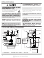
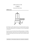
Sump, Effluent and Sewage pumps INSTALLATION MANUAL Read and save these instructions. This manual contains very important Safety Warnings and Operating Instructions. You will need to refer to it before attempting any installation or maintenance. Always keep this manual with the unit so that it will be easily accessible. Failure to read and follow these warnings and instructions could result in property damage, serious injury or death. DESCRIPTIONS UNPACKING SUMP PUMPS Sump pumps are automatic pumps used to remove ground water from sump pits. The most common application is for basement drainage to prevent flooding in residential buildings. These sumps are designed to pump clear water only. Inspect your pump. Occasionally, products are damaged during shipment. If the unit is damaged, contact our Customer Service department at the number listed on the parts and warranty sheet. EFFLUENT PUMPS Effluent pumps are pumps used to remove grey water from septic tanks, sump pits or laundry tray systems. Grey water is waste water from bathtubs, sinks, washing machines, and other kitchen appliances. The pumps are designed to pass solids 1/2 to 3/4 inches in diameter. SEWAGE PUMPS Sewage pumps are pumps used to remove waste water that contains solids up to 2 inches in diameter. The most common application is for draining bathroom waste water to a sewer or septic line. IMPORTANT SAFETY INFORMATION WARNING INDICATES A POTENTIALLY HAZARDOUS SITUATION WHICH, IF NOT AVOIDED, COULD RESULT IN DEATH OR SERIOUS INJURY. RISK OF ELECTRIC SHOCK. TO REDUCE THIS RISK, OBSERVE THE FOLLOWING WARNINGS: MAKE SURE THERE IS A PROPERLY GROUNDED RECEPTACLE AVAILABLE. This pump is supplied with a grounding conductor and grounding-type attachment plug. To reduce the risk of electric shock, be certain that it is connected only to a properly grounded, grounding-type receptacle. NEVER REMOVE THE GROUND PRONG from the plug or bypass the grounding wires. FOR ADDED SAFETY the receptacle should be protected with a ground fault circuit interrupter (GFCI). All wiring must be performed by a qualified licensed electrician and comply with the National Electric Code and all applicable local codes and ordinances. DO NOT REMOVE POWER SUPPLY CORD and strain relief or connect conduit directly to the pump. MAKE SURE THE POWER SUPPLY HAS A FUSE OR CIRCUIT BREAKER rated to handle the current (amps) noted on the pump nameplate or cordtag. © 2012 READ & FOLLOW ALL INSTRUCTIONS SAVE THESE INSTRUCTIONS — DO NOT DISCARD SAFETY GUIDELINES This manual contains information that is very important to know and understand. This information is provided for SAFETY and to PREVENT EQUIPMENT PROBLEMS. To help recognize this information, observe all safety information labeled danger, warning, caution, and notice. DO NOT USE AN EXTENSION CORD. Extension cords could present a safety hazard if not sized properly, become damaged or the connection falls into the sump. If receptacle is not within reach of the pump’s power cord, contact a qualified licensed electrician to install a new receptacle. ALWAYS DISCONNECT THE PUMP from power supply before installing, servicing or making any adjustments. DO NOT SUBMERGE PEDESTAL MOTOR or allow motor to be exposed to water. DO NOT WALK on the floor when water is present until all power is turned off. If the electric panel is in the basement, call an electrician. NEVER HANDLE A PUMP or motor with wet hands or when standing on a wet or damp floor while the pump is plugged into the power supply. WASH HANDS AFTER HANDLING. According to the state of California (Prop 65), this product may contain chemicals known to the state of California to cause cancer and birth defects or other reproductive harm. RISK OF ELECTRIC SHOCK. This pump has not been investigated for use in swimming pool and marine areas. DO NOT USE TO PUMP FLAMMABLE OR EXPLOSIVE FLUIDS such as gasoline, fuel oil, kerosene, etc. Do not use in a flammable and/or explosive atmosphere. Pump should only be used to pump clear water. Personal injury and/or property damage could result. PUMPS ARE NOT DESIGNED TO TRANSFER WATER INTENDED FOR DRINKING. Do not use the pump for moving water that will be used for potable/drinking water. Pump should only be used in applications for which it is designed. Printed on 100% Recycled Paper 200002-015 11/12 INSTALLATION MANUAL IT IS RECOMMENDED TO USE A CHECK VALVE with this pump to prevent the back-flow of fluid after each pump cycle. CAUTION INDICATES A POTENTIALLY HAZARDOUS SITUATION WHICH, IF NOT AVOIDED, MAY RESULT IN MINOR OR MODERATE INJURY. DO NOT INSTALL OR OPERATE THE PUMP IF IT HAS BEEN DAMAGED IN ANY WAY. TO REDUCE THE RISK OF HAZARDS THAT CAN CAUSE INJURY OR PROPERTY DAMAGE, OBSERVE THE FOLLOWING WARNINGS: DO NOT LIFT OR CARRY THE PUMP BY THE POWER CORD. Use the pump’s handle. IF THIS PUMP CONTAINS A SWITCH FOR AUTOMATIC OPERATION, IT IS THE INSTALLER’S RESPONSIBILITY TO MAKE SURE THE SWITCH IS ABLE TO OPERATE WITHOUT ANY OBSTRUCTIONS WITHIN THE BASIN. It is recommended that the installer test and observe the pump’s operation for several cycles after installation. IT IS RECOMMENDED TO USE RIGID PIPING AND FITTINGS to secure the pump in the basin and reduce pump movement. Pump movement can prevent the switch from operating correctly. THIS PUMP SHOULD BE INSPECTED 3 TO 4 TIMES PER YEAR for pump movement or buildup of debris on the switch or float. Reposition pump if it has moved. Remove any debris that could interfere with the operation of the switch. DO NOT USE THIS PUMP IN MUD, SAND, CEMENT, OIL OR CHEMICALS. DO NOT USE SUMP AND EFFLUENT PUMPS TO HANDLE RAW SEWAGE. AN INDEPENDENT HIGH WATER ALARM OR BACK UP PUMP SHOULD BE USED when risk of property damage from high water levels exists THE SWITCH SHOULD BE REPLACED EVERY TWO (2) YEARS. This maintenance will reduce the risk of improper pump operation, switch failure, or flooding. TYPICAL SUMP INSTALLATION DIAGRAMS Figure 1: Submersible Sump 1 Figure 2: Pedestal Sump 2 3 4 2 3 1 8 12 7 4 5 MINIMUM BASIN HEIGHT (SEE CHART A, COLUMN B) 6 7 8 MAXIMUM BASIN HEIGHT (SEE CHART B, COLUMN B) 11 5 10 6 9 9 MINIMUM BASIN DIAMETER (SEE CHART A, COLUMN A) 1. GFCI OUTLET 5. PIPE INLET 9. SUMP BASIN 2. CHECK VALVE 6. DISCHARGE PIPE 10. FLOAT ROD 3. VENT PIPE 7. SUMP PUMP 11. FLOAT GUIDE 4. GASKET/BASIN LID 8. SWITCH (SEE CHART A, ON PAGE 3) 12. SWITCH ARM 2 Printed on 100% Recycled Paper MINIMUM BASIN DIAMETER (SEE CHART B, COLUMN A) INSTALLATION MANUAL TYPICAL SUMP INSTALLATION 1. This installation must be in accordance with the National Electric Code and all applicable local codes and ordinances. Submersible Sumps 2. Use a basin that is large enough to accommodate the pump. The minimum requirements for the sump pumps are: CHART — A A B Switch Type Minimum Basin Diameter Minimum Basin Height Tether Float Switch 14 in. 22 in. Diaphragm Switch 11 in. 22 in. Vertical Float Switch 11 in. 22 in. CHART — B A B Switch Type Minimum Basin Diameter Maximum Basin Height 14 in. 24 in. Pedestal Float Switch (Figure 2, on page 2) 3. Clean the basin of all debris. 4. Assemble switch or float if needed. Refer to warranty and service parts sheet for specific directions. 5. Set the pump on a solid, level surface. Do not place pump directly on clay, earth, gravel or sand. A brick or block may be installed under the pump to provide a solid base. 6. Position pump so the switch is away from the inlet so switch is clear from incoming water. Verify the switch has at least 1 in. clearance to the side wall of the basin and is free to move throughout its movement. If optional control device or float is used, follow mounting instruction supplied with device or float. 7. Install discharge plumbing according to local, regional and state codes. Rigid PVC pipe is recommended. 8. If required, drill 1/8 in. “weep” hole in the discharge pipe 1 in. above the pump discharge. Water stream will be visible from the hole when the pump is running. The hole must be cleaned periodically. 9. Install a union to allow for easy removal of the pump for cleaning or service. 10. Install a check valve (required) to prevent back-flow. The check valve may be positioned just above the basin to allow easy removal of the pump for cleaning and service. 11. Install a gate valve or ball valve if required by local, regional or state code. 12. Secure power supply cord to discharge pipe using cable or zip ties to prevent possible switch entanglement. 13. Connect pump power supply cord to a ground fault circuit interrupter (GFCI) receptacle. 14. Fill the basin with water. The pump will start when the water level has reached the switch-on level. 15. The pump will stop when the water level has reached the switch-off level. 16. Verify the switch is operating without any obstruction from the pump, piping and basin. 17. Fill the basin with water again. While the pump is draining the basin, verify the discharge pipe is carrying the water to a point at least 3 ft. away from the foundation. If the discharge line is exposed to freezing temperatures, the pipe must be positioned in a downward slope away from the foundation so any remaining water will drain away and not freeze. 18. Secure the basin cover and gasket to the basin to prevent debris from falling into the basin, prevent personal injury, and to contain gases and/or odors. This pump is not designed to handle salt water, brine, laundry discharge, water softener, sewage, grey water, or any other application which may contain caustic chemicals and/or foreign materials. Pump damage could occur if used in these applications and will void warranty Printed on 100% Recycled Paper 3 INSTALLATION MANUAL TYPICAL EFFLUENT INSTALLATION 1. This installation must be in accordance with the National Electric Code and all applicable local codes and ordinances. 2. For sump applications, follow typical sump installation instructions (page 3). For effluent applications, continue to step 3. 3. Clean the basin of all debris. 16. Secure a basin/tank cover and gasket to the basin to prevent debris from falling into the basin, prevent personal injury, and to contain gases and/or odors. Figure 3: Effluent Pump in Septic Tank 4. Set the pump on a solid, level surface. Do not place pump directly on clay, earth, gravel, or sand. A brick or block may be installed under the pump to provide a solid base. 4 5. Verify the float switch has at least 1 inch clearance to the side wall of the basin and is free of any possible obstructions. 6. If optional control device or float is used, follow mounting instructions supplied with device or float. 7. Install discharge plumbing according to local, regional and state codes. Do not reduce the discharge pipe size below that which is provided on the pump. 8. If required, drill a 1/8 in. “weep” hole in the discharge pipe 1 in. above the pump discharge. Water stream will be visible from the hole when the pump is running. The hole must be cleaned periodically. 9. Install a union to allow easy removal of the pump for cleaning and service. 10. Install a check valve (required) to prevent back-flow. It should be installed above the union. 11. A gate valve or ball valve should be installed above the check valve as required by local, regional or state codes. 12. Connect remaining discharge pipe. The remainder of the discharge line should be as short as possible with a minimum number of turns. 2 3 5 6 7 8 9 10 11 13. Secure power supply cord to discharge pipe using cable or zip ties to prevent possible switch entanglement. 14. Connect pump power supply cord to a ground fault circuit interrupter (GFCI) receptacle. 15. Fill the basin with water. The pump will start when the water level has reached the switch-on level. Verify the pump is operating normally. If the discharge line is exposed to freezing temperatures, the pipe must be positioned in a downward slope away from the foundation so any remaining water will drain away and not freeze. 4 12 1 1. Discharge Outlet Pipe 7. Septic Tank 2. Junction Box 8. Effluent Pump 3. Pump/Switch Wires 9. Brick or Block 4.Union 10. Discharge Pipe 5. Effluent Inlet Pipe 11. Check Valve 6.Switches 12. Tank Lid Printed on 100% Recycled Paper INSTALLATION MANUAL TYPICAL SEWAGE INSTALLATION 1. This installation must be in accordance with the National Electric Code and all applicable local codes and ordinances. 2. For sump applications, follow typical sump installation instructions (page 3). For effluent applications, follow typical effluent installation instructions (page 4). For sewege applications, proceed to step 3. 3. Use a basin that is large enough to accommodate the pump. The basin diameter should be a minimum of 18 inches and the depth a minimum of 24 inches. 4. Clean the basin of all debris. 5. Set the pump on a solid, level surface. Do not place pump directly on clay, earth, gravel, or sand. A brick or block may be installed under the pump to provide a solid base. 6. Position pump in the basin so the switch is away from incoming water. Verify the float switch has at least 1 inch clearance to the side wall of the basin and is free of any possible obstructions. 7. Install discharge plumbing according to local, regional and state codes. Do not reduce the discharge pipe size below that which is provided on the pump. 8. If required, drill a 1/8 in. “weep” hole in the discharge pipe 1 in. above the pump discharge. Water stream will be visible from this hole when the pump is running. The hole must be cleaned periodically. 9. If optional control device or float is used, follow mounting instruction supplied with device or float. 10. A union should be installed above the basin to allow easy removal of the pump for cleaning and service. 17. Fill the basin with water. The pump will start when the water level has reached the switch-on level. Verify the pump is operating normally. 18. Install a basin cover and gasket to prevent debris from falling into the basin, prevent personal injury and to contain gases and odors. Figure 7: Submersible Sewage Pumps 1 11 2 10 3 4 5 7 11. Install a check valve (required) to prevent back-flow. It should be installed above the union. 8 12. A gate valve or ball valve should be installed above the check valve as required by local, regional or state codes. 13. Connect remaining discharge pipe. The remainder of the discharge line should be as short as possible with a minimum number of turns. 14. A vent pipe is required. It removes gases and odors and should be installed as required by local, regional or state codes. 15. Secure power supply cord to discharge pipe using cable or zip ties to prevent possible switch entanglement. 16. Connect pump power supply cord to a properly grounded receptacle. 9 6 1. Check Valve 7.Switch 2.Union 8. Minimum Diameter (18 in.) 3. Discharge Pipe 9. Minimum Depth (24 in.) 4. Inlet Pipe 10. Gasket/Basin Lid 5.Basin 11. Vent Pipe 6.Pump Printed on 100% Recycled Paper 5 INSTALLATION MANUAL MAINTENANCE DO NOT SUBMERGE PEDESTAL MOTOR or allow motor to be exposed to water. ALWAYS DISCONNECT THE PUMP FROM POWER SUPPLY before installing, servicing or making any adjustments. 3. Submersible pump may contain dielectric oil for cooling. Dielectric oil can be harmful to the environment. Follow state environmental laws when disposing of oil. LET PUMP COOL FOR A MINIMUM OF 2 HOURS BEFORE ATTEMPTING TO SERVICE. Submersible pumps contain oil that become pressurized and hot under normal operating conditions. 1. Submersible pump models have permanently lubricated bearings and require no additional lubrication. 4. The pump motor is equipped with automatic resetting thermal protector and may restart unexpectedly. Protector tripping is an indication of motor overloading as a result of operating the pump at low heads, excessively high or low voltage, inadequate wiring, incorrect motor conditions, or a faulty motor or pump. 2. The pump should be inspected 3-4 times per year for pump movement or buildup of debris on the switch or float. Reposition pump if it has moved. Remove any debris that could interfere with the operation of the switch. DO NOT USE AN EXTENSION CORD. Extension cords could present a safety hazard if not sized properly, become damaged or the connection falls into the sump. If receptacle is not within reach of the pump’s power cord, contact a qualified licensed electrician to install a new receptacle. TROUBLESHOOTING Symptoms Pump will not start or run Possible Cause(s) Suggested Remedies 1. Water level too low 1. Water must be at the appropriate level to activate switch 2. Blown fuse or tripped circuit breaker 2. If blown, determine cause and then either replace with proper sized fuse or reset breaker 3. Low line voltage 3. Contact an electrician 4.Motor 4. Replace pump 5.Switch 5. Replace switch 6. Inlet screen clogged 6. Remove debris 7. Switch obstruction 7. Remove obstruction to ensure free motion of switch 1. Back-flow of water from discharge pipe 1. Install check valve Pump starts and 2.Switch stops too often 3. Check valve not functioning properly or leaking 6 2. Replace switch 3. Remove and examine check valve for proper installation and free operation. Replace check valve if necessary. Printed on 100% Recycled Paper INSTALLATION MANUAL TROUBLESHOOTING (CONTINUED) Symptoms Possible Cause(s) Suggested Remedies Pump shuts off and turns on independently of switch (trips thermal overload protection) 1. Excessive water temperature 1. Pump should not be used for water above 120º F 2.Switch 2. Replace switch 3. Switch obstruction 3. Remove obstruction to ensure free motion of switch 4. Obstruction in discharge pipe 4. Remove obstruction in discharge piping 5. Low line voltage 5. Contact an electrician. Pump operates noisily or vibrates excessively 1. Worn bearings 1. Replace pump 2. Impeller obstructed or broken 2. Where applicable, remove screen and volute, clean impeller and/or replace impeller 3. Piping attachments to building structure too rigid or too loose 3. Install rubber coupling (available at local hardware stores) to isolate pump vibration from discharge plumbing Pump will not shut off 1.Switch 1. Replace switch 2. Switch obstructions 2. Remove obstruction to ensure free motion of switch 3. Restricted discharge (obstruction in piping) 3. Remove obstruction from discharge piping 4. Excessive inflow or pump not properly sized for application 4. Recheck all sizing calculations to determine proper pump size 1. Low line voltage 1. Contact an electrician 2. Inlet screen clogged 2. Remove debris 3. Broken impeller or debris in impeller cavity 3. Remove screen and volute, clean impeller and/or replace impeller 5. Pump not properly sized for application 5. Recheck all sizing calculations to determine proper pump size 6. Check valve stuck closed or installed backwards 6. Remove and examine check valve for proper installation and free operation 7. Shut off valve closed 7. Open valve Pump operates but delivers little or no water Printed on 100% Recycled Paper 7 INSTALLATION MANUAL ROUTINE SUMP MAINTENANCE We recommend you check your sump pump for proper operation at least once a year. • Make sure the pump is plugged in to a working ground fault circuit interrupter (GFCI) outlet and the cord is in good shape. In damp areas, GFCI breakers may trip, effectively shutting off the sump pump. Check in on your sump pump and reset the GFCI if necessary. • Ensure the pump itself is standing upright. Vibrations during operation can cause it to fall or tilt onto one side. This can jam the float arm so it can’t activate the pump. • Pour a bucket of water into the pit to make sure the pump starts automatically and the water drains quickly once the pump is on. If the pump doesn’t start, have it serviced or replaced. • Check the inlet screen and clear away any small stones or debris. NOTES 8 Printed on 100% Recycled Paper