1
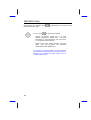
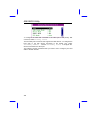
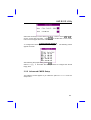
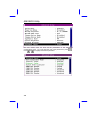
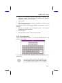
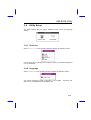
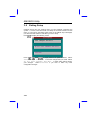
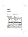
Chapter 3
AMI BIOS
This chapter tells how to configure the system by setting the BIOS parameters.
3.1
Entering the AMI BIOS Setup
To enter the AMI BIOS Setup, press
appears as shown below.
. The AMI BIOS Setup Main Menu
The AMI BIOS is in Windows form. You can use either the keyboard or a
mouse to move between the items.
To select among the Setup menu groups, use
to highlight the selected
group or simply click on the icon of the selected Setup menu.
To select among the options, you can either use the arrow keys to move the
highlight bar or simply click on the icon of the desired option.
3-1
AMI BIOS Utility
After making your selection, press
the selected menu option.
You may press
or double-click on the icon to open
to perform the following:
Resolve an address conflict due to an IRQ
address assigned to multiple slots. For more
information on IRQ assignment, see the section
3.2.3 (Chipset Features Setup).
Return to the BIOS default settings if the PnP
BIOS does not recognize the hardware
modifications under Windows 95.
To meet the PC market demands, ongoing hardware
and software enhancements are done on the system.
Therefore, it is possible that BIOS screens may be
changed without notice.
3-2
AMI BIOS Utility
3.2
Setup Menu
The figure below shows the Setup window. Use the arrow keys to highlight an
option.
3.2.1 Standard Setup
The following screen appears if you select
options:
Standard from the Setup
You can input configuration values such as date, time and disk types in this
menu.
PRIMARY MASTER AND SLAVE/
SECONDARY MASTER AND SLAVE
These parameters allow you to configure the hard disks and the IDE devices
connected to your IDE connectors. To configure the hard disk connected to
the master port of the primary IDE connector, select Primary Master
and press
. The following screen appears:
3-3
AMI BIOS Utility
To configure the hard disk connected to the slave port of the primary IDE
connector, select Primary Slave .
The secondary IDE connector also supports two IDE devices. To configure the
hard disk or the IDE device connected to the master port, select
Secondary Master . Choose Secondary Slave to configure the
device connected to the slave port.
The following are the parameters that you need to set to configure your hard
disks or the IDE devices:
3-4
AMI BIOS Utility
Type
This parameter lets you set the IDE device type that your system supports.
The options are User , Auto , CD-ROM , Type 1-46 , and Not
Installed . Select Auto to automatically configure the installed hard
disk or IDE device. Select CD-ROM if you have a CD-ROM installed in your
system. If you have an old type HDD installed, you may need to enter the
HDD parameters manually. To do this, you must set this parameter toUser .
Select Not Installed to bypass the function.
LBA/Large Mode
This enhanced IDE feature allows the system to use a hard disk with a
capacity of more than 528 MB. This is made possible through the Logical
Block Address (LBA) mode translation. Set the parameter toOff to disregard
the feature.
This parameter becomes non-configurable when the HDD Type parameter is
set to Auto .
Block Mode
This function enhances disk performance depending on the hard disk in use.
If enabled, it allows data transfers in block (multiple sectors) by increasing the
data transfer rate to 256 bytes/cycle. However, if your hard disk does not
support this function, set this parameter to Off .
This parameter becomes non-configurable when the HDD Type parameter is
set to Auto .
3-5
AMI BIOS Utility
32-bit Mode
Enabling this parameter improves system performance by increasing the hard
disk access to 32-bit mode. However, make sure that your hard disk supports
this function before you enable the parameter. Otherwise, set this parameter
to Off .
PIO Mode
Setting this parameter to On allows the system to use a faster hard disk drive.
If your hard disk does not support the PIO mode feature, set this parameter to
Off .
This parameter becomes non-configurable when the HDD Type parameter is
set to Auto .
HARD DISK TYPES
After you have set all the necessary parameters, press
HDD drive parameters appears:
Select your hard disk type. Press
or
After you have made your selection, press
. A list of the
to move among the selections.
.
If you cannot find your hard disk drive type on the list, select User . This
allows you to enter the disk parameters manually.
DATE/TIME
To set the date and time, highlight
following screen appears:
3-6
Date/Time and press
.
The
AMI BIOS Utility
Select the arrow keys to move among the items. Press or click on
or
to
set the current time and date. Press
or double-click on the Control
menu box at the upper-left corner of the window.
FLOPPY DRIVES A AND B
To configure the first floppy drive, select Floppy A . The following values
appear on screen:
After selecting the proper setting, press
Select Floppy
floppy drive.
.
B and follow the same procedure to configure the second
3.2.2 Advanced CMOS Setup
The following screen appears if you select the option Advanced from the
Setup menu:
3-7
AMI BIOS Utility
The first screen does not show all the parameters of the Advanced
Configuration menu. To scroll down the rest of the parameters, press
.
Press
or
to highlight the desired parameter.
3-8
AMI BIOS Utility
Do not change the settings of the Advanced
Setup parameters if you are not a qualified
technician. Doing so may cause fatal system
failure.
Quick Boot
During boot up, the system performs power-on self test (POST) routines.
Enable the parameter if you want to skip some POST routines during the boot
process. Set this to Disabled to let the system perform all the POST
routines and follow the specified boot-up sequence.
Boot-up Sequence
The boot-up sequence allows you to specify the system search sequence.
The selections are C:, A:, CD-ROM , A:, C:, CD-ROM
and
CD-ROM, A:, C:. If you have a bootable CD-ROM installed, you may
set the CD-ROM as the first priority. The default is A:, C:, CD-ROM.
Boot-up Numlock
Setting this parameter to On enables the numeric function of the numeric
keypad. Set this parameter to Off to disable the function. Disabling the
numeric function allows you to use the cursor control numeric keypad. The
default setting is Off .
3-9
AMI BIOS Utility
Floppy Drive Swap
This parameter allows you to swap floppy drives. For example, if you have two
floppy drives (A and B), you can assign the first drive as drive B and the
second drive as drive A or vice-versa. Disable the parameter to bypass the
function. The default is Disabled .
Floppy Drive Seek
When enabled, BIOS detects whether there is a floppy disk drive installed in
the system. Disable the parameter to skip the function.
Typematic Rate
This parameter allows you to control the speed at which the system registers
repeated keystrokes.
System Keyboard
Set this parameter to Presen t if there is a keyboard connected to the
system. If none, select Absent .
Primary Display
This function specifies the VGA type in use. The selections areVGA/EGA,
and Absent . The
CGA 40 x 25, CGA 80 x 25, Mono,
default setting is VGA/EGA .
Password Check
This parameter lets you set when to check for the password. When set to
Always , a password prompt appears every time you turn on the computer
and when you enter Setup. When set to Setup , the password prompt
appears when you try to enter setup. The Optimal and Turbo default setting is
Setup .
OS/2 Compatible Mode
Enable the parameter if your system is utilizing an OS/2 operating system and
has a memory size of more than 64 MB. Otherwise, set this toDisabled .
The default setting is Disabled .
3-10
AMI BIOS Utility
Internal Cache
This function lets you enable or disable the internal cache.
External Cache
This function lets you enable or disable the external cache.
System BIOS Cacheable
Enabling this parameter allows you to cache the system BIOS to further
system performance. The default settings is Enabled.
C000 ~ DC00, 16K Shadow
These parameters are for shadowing expansion cards with ROM. You need to
know the specific addresses that ROMs use to shadow the expansion cards
before you set any of these parameters. If you do not know this information,
enable all the ROM shadow settings. This ensures shadowing of any present
ROMs and reduces the available memory . Select Cached if the data in the
chosen addresses are already copied into RAM.
The F000 and E000 addresses are exclusively
shadowed for BIOS.
3-11
AMI BIOS Utility
3.2.3 Chipset Features Setup
The Chipset Features Setup controls the board chipset settings. The controls
for this menu are the same as for the previous screens. The Chipset Features
Setup screen appears as follows.
To scroll down the rest of the parameters, press
highlight the desired parameter.
. Use
or
to
Memory Hole
This option lets you assign the system memory area for ISA cards installed in
your system to avoid memory conflicts.
The available settings are
512~640K, 15~16M and Disabled .
3-12
AMI BIOS Utility
DRAM Timing Setting
The selections for this parameter are 60 ns, 70 ns, and Manual . If
you select either 60 ns or 70 ns , the DRAM Timing subparameters
become non-configurable since BIOS automatically sets the values. Select
Manual if you want to specify your own parameter settings.
FAST MA TO RAS# DELAY
This option specifies the wait state between the master address (MA) and row
address strobe (RAS) signals. The selections are 1 clock and 2
clocks .
EDO:SPM READ BURST TIMING
This parameter adjusts the read wait state for Extended Data Out (EDO)
DRAM and Standard Page Mode (SPM) DRAM. Every time the CPU reads the
second-level cache miss, it reads four continuous memory cycles on four
continues addresses from the EDO and SPM cache.
The selections for this parameter are x444/X444, X333/X444,
X222/X333, and X3222/X333 . The value of X depends on the DRAM
Lead-off Timing parameter setting.
DRAM WRITE BURST TIMING
This parameter adjusts the write wait state between the second-level and the
DRAM cache. The second-level cache is processed through write-back
method and each cache write process consists of four continuous cache write
cycles.
The parameter settings are X444, X333, and X222 . Faster DRAMs
require shorter wait states. The value of X depends on the DRAM Lead-off
Timing parameter setting.
FAST RAS TO CAS DELAY
This option specifies the wait state between the row address strobe (RAS) and
column address strobe (CAS) signals. The available settings are3 clocks
and 2 clocks .
DRAM LEAD-OFF TIMING
This option specifies the DRAM waiting time or the delay before data can be
accessed. Some DRAMs may require a longer delay to access data. The
selections are 11-7-3, 10-6-3, 11-7-4, and 10-6-4 .
3-13
AMI BIOS Utility
REFRESH RAS# ASSERTION
This function controls the number of clocks required to assert RAS#
refresh cycles. The available settings are 4 clocks and 5 clocks .
for
FAST EDO PATH SELECT
Enable this option to select a fast path for CPU to DRAM read cycles to
minimize the lead-off time. This is applicable only for EDO DRAMs. For other
DRAM types, we recommend that you set this to Disabled .
SDRAM CAS# LATENCY
This parameter controls the wait state between SDRAM row address strobe
and SDRAM CAS signals.
SDRAM RAS# TIMING
This parameter controls the RAS# precharge, RAS# active-to-precharge time,
and refresh-to-RAS# active signal delay.
8-bit I/O Recovery Time (Sysclk)
This parameter allows you to set the response time of the 8-bit I/O devices
connected to your system. The settings range from 1-8 SYSCLK and
Disabled .
16-bit I/O Recovery Time (Sysclk)
This parameter allows you to set the response time of the 16-bit I/O devices
connected to your system. The settings range from 1-4 SYSCLK and
Disabled .
ISA Clock Divisor
This option specifies the ISA bus clock divisor.
PCICLK/4 and PCICLK/3 .
The selections are
Peer Concurrency
Enable the parameter to allow the CPU to run secondary DRAM PCI master
cycles to target PCI peer devices. Select Disabled to hold the CPU bus.
The default setting is Disabled .
3-14
AMI BIOS Utility
PCI 2.1 Compliant
This parameter lets you enable or disable the PIIX3 PCI register passive
release functions. When enabled , the PIIX3 controls the USB operation to
make sure that the system complies with the PCI Revision 2.1 specification.
Select Disabled to disregard the functions.
USB Function Enabled
This parameter lets you enable or disable the USB device(s) connected to your
system, if any. The default is Disabled .
The USB function shares INTD with PCI slot 4.
Therefore, if you enable the USB function, only
PCI cards that do not require IRQ, such as VGA,
can be installed in slot 4. The PnP BIOS
assigns an IRQ to VGA if the VGA requests for
it.
3-15
AMI BIOS Utility
3.2.4 Power Management Setup
To take advantage of the power-management feature, select Power
Management from the Setup menu. The following screen appears:
To scroll down the rest of the parameters, press
highlight the desired parameter.
. Use
or
to
Power Management/APM
This parameter enables or disables the advanced power-management
function.
3-16
AMI BIOS Utility
Instant On Time-out (Minutes)
This parameter is configurable only if the Power Management/APM parameter
is set to Instant On . This option lets you specify when to resume system
power after being in power-saving mode for a certain period of time.
Green Monitor Power-down State
This function lets you set when to power down your green PC monitor. The
options are Standby, Suspend, and Off . The default is Standby .
Video Card Power-down Mode
This option allows you to set when to power down your system display card.
The card function returns to full power once the system resumes to normal
mode. The selections are Standby, Suspend, and Disabled .
The default setting is Standby.
Hard Disk Power-down Mode
This option lets you set when to “spin down your IDE hard disk. The disk
returns to full speed once the system resumes to normal mode. The available
settings are Standby, Suspend, and Disabled . The default
setting is Suspend.
Hard Disk Time-out (Minutes)
This option lets you specify when to set the hard disk to the specified powerdown mode.
The settings range from 1 ~ 15 Minutes and
Disabled .
Standby Time-out (Minutes)
This function lets you set when to put the system into standby mode. In
standby mode, the CPU clock slows down. Any event detected returns the
system to full power. The settings range from 1 ~ 15 Minutes and
Disabled .
Suspend Time-out (Minutes)
This function lets you set when to put the system into suspend mode. In
suspend mode, the CPU clock stops. Any event detected returns the system
to full power. The settings range from 1 ~15 Minutes and Disabled .
3-17
AMI BIOS Utility
Slow Clock Ratio
When the system enters the standby mode, the CPU clock starts to slow
down. This parameter lets you set the “slow down” clock ratio. The
selections are from 1:1, 1:2, 1:4, 1:8, 1:16, 1:32,
1:64, and 1:128 .
Display Activity
This function lets you check the activity of the monitor. When set to
Monitor , any detected activity from the display resumes the system to
normal mode. When set to Ignore , the power management function
bypasses the display activities detected.
IRQ 3, 4, 5, 7, 9, 10, 11, 12, 13, 14, and 15
These parameters enable or disable specific I/O devices as wake up events in
the power management mode. Any activity detected from the enabled IRQs
resets the power-management timers and returns the system to normal mode.
3-18
AMI BIOS Utility
3.2.5 PCI/PnP Setup
The PCI/PNP Setup allows you to specify the setting for your PCI devices.
The screen below appears on screen if you select PCI/PnP from the Setup
menu.
To scroll down the rest of the parameters, press
highlight the desired parameter.
. Use
or
to
Plug-and-Play Aware O/S
Enable this parameter only if you have a Plug-and-Play operating system,
such as Windows 95.
3-19
AMI BIOS Utility
PCI IRQ Priority Auto Setting
Set this parameter to Yes to automatically set the appropriate available
interrupt for each PCI slot. Select No if you prefer to manually set the
interrupts.
1st, 2nd, 3rd, and 4th Available IRQ
These parameters are configurable only if the PCI IRQ Priority Auto Setting
parameter is set to No . When configurable, these let you specify the ranking
of the interrupts which you can assign to the PCI devices installed in your
system.
PCI VGA Palette Snoop
PCI devices support the palette snooping technique that enables the device to
control access to their palette registers. Enable this parameter to activate the
palette snooping function in the PCI VGA devices installed in the system.
Check your VGA card manual for more information about his function. The
default setting is Disabled .
PCI IDE Card
This function allows you to select the PCI slot(s) that you want to enable, if
there is any offboard PCI IDE card present. Set this parameter toAuto to
automatically configure the installed PCI card.
PCI IDE Primary IRQ
This parameter lets you assign an IRQ for the IDE device connected to your
primary IDE connector. The options are INTA, INTB, INTC, INTD,
Hardwired and Disabled . If the PCI IDE Card parameter is set to
Auto , this parameter becomes non-configurable.
PCI IDE Secondary IRQ
This parameter lets you assign an IRQ for the IDE device connected to your
secondary IDE connector. The options are INTA, INTB, INTC,
INTD, Hardwired and Disabled . If the PCI IDE Card parameter is
set to Auto , this parameter becomes non-configurable.
3-20
AMI BIOS Utility
Reserved Memory Size for ISA
This option lets you specify the memory area reserved for Legacy/ISA devices.
Reserved Memory Base for ISA
This option lets you specify the memory base address reserved for Legacy/ISA
devices.
3-21
AMI BIOS Utility
3.2.6 Peripheral Setup
Select Peripheral
appears.
from the Setup menu and the following screen
Onboard FDC
This parameter enables or disables the floppy drive controller.
Onboard Serial Port 1
This parameter allows you to select the address for the first serial port. The
available settings are Auto, 3F8h, 2F8h, 3E8h, 2E8h,
and
Disabled . Selecting Disabled deactivates the port.
Onboard Serial Port 2
This parameter allows you to select the address for the second serial port. The
available settings are Auto, 3F8h, 2F8h, 3E8h, 2E8h,
and
Disabled . Selecting Disabled deactivates the port.
SERIAL PORT 2 MODE
This parameter allows you to specify the serial port 2 mode. The available
mode selections are:
•
Normal - Sets serial port 2 to operate in normal mode. This is the
default setting.
3-22
AMI BIOS Utility
•
HPSIR -
•
ASKIR - Select this setting only if the IR function is activated (i.e., an
Select this setting only if the InfraRed (IR) function is
activated (i.e., an IR module is installed in your system). This setting
allows infrared serial communication at a maximum baud rate of 115K
baud.
IR module is installed in your system). This setting allows infrared serial
communication at a maximum baud rate of 19.2K baud.
Onboard Parallel Port
This parameter allows you to select the address for the parallel port. The
available settings are Auto,
378h, 278h, 3BCh,
and
Disabled . Selecting Disabled deactivates the parallel port.
PARALLEL PORT IRQ
This parameter allows you to set the interrupt for the parallel port. The default
setting is 7 .
PARALLEL PORT MODE
This parameter specifies the parallel port mode. The mode options areSPP,
EPP, and ECP . The default is SPP.
Onboard IDE
This parameter enables or disables the IDE device(s) connected to your
system. The selections are Primary, Secondary, Both,
and
Disabled .
3-23
AMI BIOS Utility
3.3
Security Setup
The Security window contains the password and anti-virus features.
3.3.1 Supervisor Password
The use of password prevents unauthorized use of your computer. If you set a
Supervisor password, the system prompts for this password before granting
access to Setup or system boot, depending on the Password Check setting in
the Advanced CMOS Setup menu.
To set a Supervisor password, select
window. The following screen appears:
Supervisor from the Security
Follow these steps to set up a password using the keyboard:
3-24
AMI BIOS Utility
1.
Type in a six-character password using letters, numbers, or a
combination of both. When you type the characters, they appear as
asterisks on the password screen boxes.
2.
Press <Enter>.
3.
Retype the password when a password confirmation box appears asking
you to retype the password.
You may also use the mouse and the characters on the screen to set up a
password.
1.
Click on six characters from the password screen.
appear on the boxes as asterisks.
2.
Click on <Enter>.
3.
Enter the password when a confirmation box appears.
The characters
3.3.2 User Password
To set a User password, select
following screen appears:
User from the Security window.
The
For instructions on how to enter a password, follow the procedures listed in
section 3.3.1.
If you set a Supervisor and a User password, you
can enter either of the two entries when prompted
for a password before system boot or entering
3-25
AMI BIOS Utility
Setup.
3.3.3 Anti-virus
Select Anti-Virus from the Security window to display the following
option box.
The virus protection options allow you to enable or disable the virus protection
feature.
3-26
AMI BIOS Utility
3.4
Utility Setup
The Utility window lets you change WinBIOS Setup colors and language
setting.
3.4.1 Color Set
Select Color
Set from the Utility window to display the following screen.
Use the arrow keys or simply click an option to select your desired background
color for WinBIOS.
3.4.2 Language
Select Language from the Utility window to display the following screen.
The system language currently supported is only English.
option is non-configurable and is for display only.
Therefore, this
3-27
AMI BIOS Utility
3.5
Default Setup
The Default window allows you to select a group of settings for all WinBIOS
Setup options.
3.5.1 Original
When you select Original , a dialog box prompts you to restore the
original BIOS default values. Select No to keep your current settings. Select
Yes to restore the original values.
3.5.2 Optimal
When you select Optimal , a dialog box prompts you to load the values that
will help your system deliver optimum performance. Select Yes to load the
BIOS optimum values. Select No to keep your current settings.
3-28
AMI BIOS Utility
3.5.3 Turbo
When you select Turbo , a dialog box prompts you to load the Turbo values
to further enhance system performance.
Select Yes to load the Turbo
values. Select No to keep your current settings.
In case your system operation becomes unstable and incompatibility problems
occur, unload the Turbo values and
3-29
AMI BIOS Utility
3.6
Exiting Setup
Carefully check your new settings when you have finished configuring the
system. If correct, write them down and keep the recorded values in a safe
place. If in the future, the battery loses power or the CMOS chip is damaged,
you will know what values to enter when you rerun setup.
Press
to display the following screen.
Press
or
, then
or simply click on an option to select. Select
Save changes and Exit to save the changes that you made. Select
Do not save changes and Exit to leave setup without saving
your changes.
Select Continue if you want to make any more
configuration changes.
3-30
AMI BIOS Utility
3.7
NCR SCSI BIOS and Drivers
The NCR 53C810 SCSI BIOS resides on the same flash memory chip as the
system BIOS. To use the onboard NCR BIOS, you need to install an NCR
53C810 SCSI controller card in your system.
All SCSI devices that you install in your system require software drivers. The
NCR SCSI BIOS directly supports SCSI hard disks under DOS, Windows and
OS/2. It also uses DOS-format and SCO UNIX-format support floppy disk
device drivers that come with the NCR 53C810 SCSI controller card. The
DOS-format device drivers are for SCSI devices used with DOS, Windows NT,
Novell NetWare and OS/2. The SCO UNIX-format device drivers are for SCSI
devices used with SCO UNIX. These drivers offer higher performance than
the direct BIOS support.
To use the device drivers, you must install them in your system hard disk drive
and add them to your system configuration files. For detailed installation
instructions, see the README files that come with the drivers.
3.8
AMI Flash Utility
The AMI Flash Utility allows you to upgrade the system BIOS. To get the AMI
flash utility and the upgrade BIOS file, contact your local distributor or visit our
homepage at http://www.aopen.com.tw . The file name of AMI flash utility is
AMIFLASH.EXE, run this program under DOS, follow the instruction on the
screen, actually, you need only input the BIOS file name. After programming,
reboot your system for the new BIOS to take effect.
Warning: Make sure you use AMI Flash Utility
version 5.23 or later, the version before 5.23
has bug to program INTEL 12V Flash ROM,
and after the programming, the system may
fail to reboot.
Warning: Be sure you get the correct BIOS file
and carefully read the instruction and notice
from AOpen homepage. Use incorrect BIOS
file on incorrect version of mainboard may
damage your system.
3-31