1
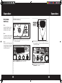
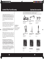
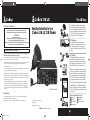
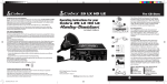
How to Use Your Cobra 29 LX
Contents
Features..........................................................................................................1
The CB Story..................................................................................................A1
FCC.Regulations,.FCC.Warnings.&.Included.Accessories
Controls & Indicators.................................................................................A2
Our Thanks to You......................................................................................A3
. Customer.Support
Installation
. Location.&.Mounting/Connection...................................................2
. Antennas
. CB.Antenna.&.Marine.Installation....................................................6
Ignition Noise Interference....................................................................7
Operating Your 29 LX
. Turning.On.Your.CB............................................................................... 8
. Setting.Channel.Selector..................................................................... 9
. Calibrate.For.SWR.(Standing.Wave.Ratio)..................................... 10
. To.Receive................................................................................................. 12
. Selecting.a.Channel............................................................................... 13
. S-Meter....................................................................................................... 13
. To.Transmit............................................................................................... 14..
. Setting.Dynamike®................................................................................ 15
. Menu.Mode.............................................................................................. 16
. Setting.the.Clock.................................................................................... 17..
. Setting.the.Alarm................................................................................... 17
. Setting.the.Count.Down.Timer......................................................... 18..
. Key.Tones.Mode..................................................................................... 18..
. Radio.Check.Mode................................................................................. 19
. Setting.Display.Color.Mode................................................................ 20
. Setting.Brightness.Mode..................................................................... 21.
. Setting.Contrast.Mode......................................................................... 21
. Weather.Information............................................................................. 22
. Weather.Channels.................................................................................. 23
. Weather.Alert.Mode.............................................................................. 24
. Setting.Weather.Alert.Scan................................................................ 24
. Setting.Weather.Auto.Scan................................................................ 24
. Software.version/Factory.Settings................................................... 25
. NB-ANL/Off.(Noise.Blanker/Automatic.......................................... 26
. Noise.Limiter.Switch)
. RF.Gain.Control....................................................................................... 26
. Program.Memory.Channels................................................................ 27
. Scan/Memory.Scan................................................................................ 27
. Scan.CB.Channels................................................................................... 28
. Scan.Memory.Channels....................................................................... 28
. Dimmer.Control...................................................................................... 28
. Setting.Squelch....................................................................................... 29
. S/RF.Meter................................................................................................. 30
. External.Speaker..................................................................................... 31
. PA.(Public.Address)................................................................................ 32
. Home.And.Office.Set-Up..................................................................... 34
. Temporary.Mobile.Set-Up................................................................... 35
How Your CB Can Serve You.................................................................. 36
. A.Few.Rules.You.Should.Know.........................................................36
. Channel.9.Emergency.Messages......................................................36
. CB.10.Codes..............................................................................................38
Frequency Ranges......................................................................................40
29 LX Specifications...................................................................................41
Warranty Information...............................................................................42
Optional Accessories................................................................................. 43
Optional Accessories Order Info..........................................................44
If You Need Service/Trademark Info.................................Back.Cover
Features of This Product
• Selectable 4-Color LCD Display
• 10 Weather Channels
• Weather Scan
• Emergency Weather Alert
• 40 CB Radio Channels
• 40 Channel Scan
• Memory Channels
• Channel Frequency Read-Out
• Radio Check Diagnostic
• Clock/Timer/Alarm
• Heavy-Duty Dynamic
Microphone
• Full 4 Watts AM RF Power Output
• SWR Calibration Meter
• Instant Channel 19 and 9
• Front Panel 4-Pin Microphone
Connector
• Switchable Automatic Noise
Limiter & Noise Blanker
• Adjustable Dynamike Boost
• Tactile Controls
• 9 Ft Mic Cord
• Programmable Dimmer Control
• RF Gain
1
29LX_MANL_vC.indd 1
12/17/10 1:51 PM
Installation
Installation
Location
Location
Plan.location.of.transceiver.and.microphone.
bracket.before.starting.the.installation.
Select.a.location.that.is.convenient.for.operation,.
yet.does.not.interfere.with.the.driver.or.passenger.
The.transceiver.is.usually.mounted.to.the.underside.of.the.dash.with.the.microphone.bracket.
beside.it.
Mounting and
Connection
Mounting and Connection
1
Note
The transceiver is held in the
universal mounting bracket by
two thumbscrews which allow
for adjustment at a convenient
angle.
. .Hold.the.radio.with.the.mounting.bracket.in.
the.exact.desired.location..If.there.is.no.interference,.remove.the.bracket.and.use.it.as.a.
template.to.mark.the.location.for.the.mounting.screws.
3
. .Connect.the.antenna.cable.plug.to.the.receptacle.marked.“ANT”..on.the.back.of.the.unit..
The bracket includes two selftapping screws and star washers. The mounting must be
mechanically strong, conveniently located.
2
. Drill.the.holes.and.secure.the.bracket.
continued
2
29LX_MANL_vC.indd 2-3
3
12/17/10 1:51 PM
Installation
Installation
Note
Before installing the CB radio,
visually check the vehicle’s
battery connection to determine which terminal, positive
or negative, is grounded (positive is the larger of the two)
to the engine block (or chassis). A negatively grounded
vehicle has its negative lead
grounded to the chassis.
Note
6
. .Plug.power.cable.into.back.of.unit.marked.
“Power”...Be.sure.to.observe.polarity.markings.
7
. .Mount.the.microphone.
bracket.on.either.side.
of.the.unit.(driver’s.left).
using.two.screws.supplied..Bracket.should.be.
placed.under.the.dash..
so.microphone.is.readily.
accessible.
Connecting to an accessory fuse
prevents the unit from being left
on accidentally, and also permits operating the unit without
running the engine.
4
Note
In positive ground vehicles the
red wire goes to the chassis and
the black wire is connected to
the ignition switch.
5
Note
When connected to an accessory fuse, unit will self test
the emergency weather alert
automatically when ignition
is turned on. Turns itself on & off.
Note
If microphone is not
connected, audio will not
be heard at speaker.
. .Connect.the.black.lead.to.the.negative.side.
of.the.vehicle..This.is.usually.the.chassis..Any.
convenient.location.with.a.good.electrical.
contact.(remove.paint).may.be.used..
8
4
29LX_MANL_vC.indd 4-5
. .In.a.negative.grounded.vehicle,.connect.the.
red.lead.of.the.DC.power.cord.to.an.accessory.
12.volt.fuse.
..Attach.the.4-pin.microphone.cable.to..
receptacle.on.front.of.unit.and.install.unit..
in.bracket.securely.
5
12/17/10 1:51 PM
Antennas
Ignition Noise Interference
CB Antenna
CB Antenna
Since.the.maximum.allowable.power.output.of.
the.transmitter.is.limited.by.the.FCC,.the.antenna.
is.critical.in.affecting.transmission.distance..Only.a.
properly.matched.antenna.system.will.allow.maxiNote
mum.power.output..Cobra.loaded.type.antenna.
For optimum performance in
models.are.highly.recommended.for.most.instalpassenger cars the ideal anten- lations..For models with Weather Feature (WX),
na location is on the center of
a Dual Band (Center Load/Base Load) antenna
the roof. Second choice is on the is recommended..Consult.your.Cobra.dealer.for.
center of the trunk.
further.details,.or.call.773.889.3087.and.speak.to.a.
Cobra.representative..
Note
Because many newer trucks
feature fiberglass door skins,
the outside mirror must be
grounded to the chassis via a
ground strap, if the antenna is
mounted on the mirror bracket.
Use.of.a.mobile.receiver.at.low.signal.levels.is.
normally.limited.by.the.presence.of.electrical.
noise..The.primary.source.of.noise.in.automobiles.is.from.the.alternator.and.ignition.system..
Typically,.when.signal.level is.adequate,.the.background.noise.does.not.present.a.serious.problem..
Also,.when.extremely.low.level.signals.are.being.
received,.the.transceiver.may.be.operated.with.
the.vehicle’s.engine.turned.off..The.unit.requires.
very.little.current.and.therefore.will.not.significantly.discharge.the.vehicle’s.battery.
Even.though.the.Cobra.29.LX.has.an.automatic.
noise.limiter,.in.some.installations.ignition.interference.may.be.high.enough.to.make.good.communications.impossible..Many.possibilities.exist.
and.variations.between.vehicles.require..
different.solutions..Consult.your.Cobra.dealer.or.
a.2-way.radio.technician.for.help.in.locating.the.
source.of.a.severe.noise.
Note
3-way Combination Antennas
are also available which allow
operation of all three bands
(AM-FM & CB), using a single
antenna. However, this type
of antenna usually results in
less than normal transmit and
receive range when compared
to a standard-type “Single
Band” CB antenna. Call 773889-3087 for further information.
.1 A
. .standard.antenna.connector.is.provided..
on.the.transceiver.for.easy.connection.
Marine Installation
The.transceiver.will.not.operate.at.maximum..
efficiency.in.a.boat.without.a.ground.plate,.
(unless.it.has.a.steel.hull)..Before.attempting.
installation.,.consult.your.dealer.for.information.
regarding.an.adequate.grounding.system.and.
prevention.of.electrolysis.between.fittings.in.the.
hull.and.water..
6
29LX_MANL_vC.indd 6-7
7
12/17/10 1:51 PM
Operation
Operation
Turning On
Turning On
Setting Channel
Selector
Setting Channel Selector
Make.sure.the.power.cord,.antenna.and.microphone.are.connected.to.their.proper.connectors.
before.starting..
NB/ANL
2
NB/ANL SWR 1.5
ANL
S/RF
S/RF
SWR
CAL
OFF
3
CAL
SQ
TX
RX
RF
SWR/CAL
VOL
3
3
SIG 1
5 79
+30dB
DYNAMIKE
MIN
M
E
Note
PU SH EN
TE
NU
MEM
Press CB/WX/PA to select CB,
weather channels or PA (public
address) modes.
WX !
R
RF GA
MIN
. .Select.one.of.forty.channels.and.adjust..
volume..The.selected.channel.(1.through.
40).will.be.indicated.by.the.readout.directly.
above.the.channel.selector.knob
.1 R
. otate.the.On/Off Volume.knob.clockwise.to.
turn.unit.on.and.adjust.to.a.normal.listening.
level.
NB /ANL
2
NB/ANL SWR 1.5
ANL
S/RF
S/RF
SWR
CAL
OFF
CAL
SQ
SCAN
TX
CB /WX/
3
SIG 1
PA
5 79
+30dB
DYNAMIKE
M
EN
U SH EN
U P
TE
MEM
MIN
2
8
DIM
ESC
WX !
R
RF GAIN
MIN
29LX_MANL_vC.indd 8-9
CH 9/
19
MEM SCAN
RX
RF
SWR/CAL
VOL
3
DELTA TUNE
MAX
T BACK
SWR
CAL
OFF
. .Press.the.CB/PA/WX.button.to.change.modes..
9
12/17/10 1:51 PM
Operation
Calibrate For
SWR (Standing
Wave Ratio)
Operation
Calibrate for SWR (Standing Wave Ratio)
PUSH &
HOLD
SWR.calibration.is.done.to.properly.adjust.the.
length.of.the.antenna.and.to.monitor.the.quality.
of.the.coaxial.cable.and.all.RF.connections.
This.calibration.is.critical.in.order.to.achieve.optimum.performance.
Note
NB /ANL
2
SWR 1.5
S/ RF
3
RX
RF
3
SIG 1
SWR /CAL
VOL
SQ
5 79
+30dB
M
DYNAMIKE
EN
U SH EN
U P
TE
MEM
R
3
NB /ANL
OFF
2
NB/ANL SWR 1.5
ANL
MIN
S/ RF
S/RF
SWR
CAL
. 1 Select.channel.20.SWR/CAL
VOL
OFF
3
CAL
M
RF
SQ
. Push and hold.mic.button.
SCAN
TX
CB /WX/
3
SIG 1
PA
5 79
+30dB
DYNAMIKE
M
E
PU SH EN
TE
NU
R
RF GAIN
MIN
MIN
Press.SWR/CAL button.to.select.CAL.
CH 9/
19
Note
The reading will be slightly
higher on Channels 1 and 40
compared to Channel 20.
MEM SCAN
RX
4
2
Calibration must be made in an
open area (never in a garage).
Vehicle doors must be closed.
No one should be standing near
the antenna. (See your antenna
directions for more complete
information).
CAL
DELTA TUNE
MAX
T BACK
DIM
ESC
SWR
CAL
OFF
. .While.holding.mic.
button.adjust.the.
SWR CAL.knob.so.
the.meter.swings.
to.the.CAL.mark.on.
the.meter.(located.
on.the.right)..
continued
10
29LX_MANL_vC.indd 10-11
11
12/17/10 1:51 PM
Operation
Operation
Calibrate for
SWR continued
S/RF
To Receive
RX
5 79
+30dB
3
SIG 1
SWR/CAL
When switched to SWR
mode the meter reading
should ideally be as far to the
left as possible. Anything over
3 is not acceptable. A slight
antenna height adjustment
(higher or lower) may be
required. Repeat recalibration
steps.
CAL
RF
SWR
VOL
3
2
SWR 1.5
Note
Selecting A
Channel
Selecting A Channel
NB/ANL
SQ
M
DYNAMIKE
OFF
EN
RX
F
U SH EN
U P
TE
3
SIG 1
MEM
5 79
+30dB
R
DYNAMIKE
M
EN
U SH EN
U P
TE
MEM
R
RF GAIN
M
MIN
MIN
MIN
5
6
. .Release.the.PTT.button,.press.and.release.the.
S/RF-SWR CAL.button.to.the.SWR.position..
Then.press.the.PTT.button.to.read.the.SWR.
reading.
.
. .Repeat.the.same.steps.two.through.five.on.
Channel.1.and.40..This.will.check.SWR.for.all.
channels.
S-Meter
To Receive
S-Meter
Swings.proportionately.to.strength.of.incoming.
signal.when.receiving.
SWR 1.5
2
S/RF
S/RF
SWR
CAL
OFF
SQ
S/RF
CAL
2
3
CAL
RX
3
SIG 1
DYNAMIKE
MIN
SIG 1
5 79
+30dB
M
E
PU SH EN
TE
NU
MEM
12
29LX_MANL_vC.indd 12-13
3
5 79
+30dB
W
R
VOL
SQ
DYNAMIKE
M
EN
U SH EN
U P
MIN
1
1
RF
RX
RF
SWR /CAL
VOL
3
MAX
Unit.should.be.in.CB.mode..Rotate.channel
selector.clockwide.or.counter-clockwise.to.
select.desired.channel.
1
NB/ANL
NB/ANL SWR 1.5
ANL
DEL
..Rotate.the.On/Off Volume.knob.clockwise..
The.RX.icon.will.be.displayed.
...The.S/RF-SWR-CAL.switch.must.be.in.the.S/RF.
setting.to.read.the.meter.
13
12/17/10 1:51 PM
Operation
To Transmit
Operation
To Transmit
Setting ®
Dynamike
Setting Dynamike®
This.controls.the.microphone.sensitivity..
(outgoing.audio.level).
Caution!
NB /ANL
Be sure to read the F.C.C. Rules
and Regulations included with
this unit before transmitting.
2
NB/ANL SWR 1.5
ANL
Be sure the antenna is properly
connected to the radio before
transmitting. Prolonged transmitting without an antenna,
or a poorly matched antenna,
could cause damage to the
transmitter.
S/ RF
S/RF
SWR
CAL
1
. .Select.desired.channel.
Transmit
PUSH &
HOLD
OFF
CAL
SQ
TX
RX
RF
SWR/CAL
VOL
3
3
SIG 1
5 79
+30dB
DYNAMIKE
M
EN
U SH EN
U P
TE
M
R
MIN
.3 I.nitially,.set.fully.clockwise.so.that.maximum.
voice.volume.is.available..Dynamike.may.
have.to.be.reduced.in.some.conditions.
.2 P
. ush and hold.mic.button.to.transmit..
Transmitter.is.now.activated..When.transmitting,.hold.the.microphone.two.inches.from.
your.mouth.and.speak.in.a.clear,.normal.voice..
Release.to.receive.
14
29LX_MANL_vC.indd 14-15
15
12/17/10 1:51 PM
Operation
Operation
Menu Mode
Using.the.clock,.alarm.and.countdown.functions.
To.set.the.clock,.press.Menu/Enter.knob.and.
select.Set Clock..
Used.to.program.special.features..Menu/Enter.
knob.is.used.to.move.cursor.to.desired.feature..
to.program.. NB /ANL
Note
Use Dim/Escape button to exit
from any routine back to CB
standby mode.
S/ RF
S/RF
SWR
CAL
VOL
3
2
NB/ANL SWR 1.5
ANL
CAL
SET CLOCK
ALARM CLOCK
SET COUNT DOWN
TX
RX
RF
3
SIG 1
SWR/CAL
SQ
5 79
+30dB
M
DYNAMIKE
EN
U
OFF
3
2
NB/ANL SWR 1.5
S/ RF
S/RF
SWR
CAL
CAL
SQ
5 79
+30dB
3
SIG 1
DYNAMIKE
S/RF
SWR
CAL
EN
OFF
S/RF
SWR
CAL
RF
SWR /CAL
VOL
SQ
3
2
CAL
S/RF
MIN
5 79
+30dB
3
M
DYNAMIKE
WX !
M
S/RF
SWR
CAL
MIN
OFF
SWR/CAL
U SH EN
U P
TE
VOL
2
VOL
OFF
29LX_MANL_vC.indd 16-17
SQ
U SH EN
U P
TE
OFF
SIG
MEM
R
WX !
Level.5:
3
EXIT
TX
OFF
3
SIG 1
MINMIN
5 79
+30dB
DYNAMIKE
M
E
U
CB /W
S/RF
PA
SWR
PU SH EN
CALT E R
CH 9/
19
SWR
MEM
WX !
3
1
SIG
SWR
CAL RF GAIN
3
PA
T BACK
CAL
SCAN
TX
RX
OFF
/WX/
CB
DELTA TUNE
CH 9/
19
DYNAMIKE
PA
M
EN
X/
CB /WMAX
PA
DIM
ESC
OFF
MEM
DIM
ESC
Note
CH 9/
19
MEM SCAN
CB /WX
/
PA
DIM
ESC
WX !
R
Setting the Alarm
RF GAIN
DELTA TUNE
T BACK
Your.29.LX.can.be.utilized.as.an.alarm.clock...
To.set.the.alarm,.press.Menu/Enter.knob.and.
SWR
select.Set Alarm..
CAL
SWR
CAL
DIM
ESC
MAX
MIN
CH 9/
19
SET CLOCK
ALARM CLOCK
SET COUNT DOWN
DIM
ESC
T BACK P USWR
S
H EN
CAL
U
MEM SCAN
MIN
CH 9/
19
MEM SCAN
5 79
+30dB
SCAN
SQ
TE
MEM
OFF
SCAN
Setting the
Alarm
CH 9/
19
MEM SCAN
CB /WX
PA
/
DIM
ESC
WX !
R
Rotate.Menu/Enter.knob.clockwise.to.select.Set
SWR
RF GAIN
DELTA TUNE
T BACK
Alarm Time..Follow.instructions.above.for.setting.CAL
the.alarm.time.and.AM.or.PM.
WX !
RF GAIN
DELTA TUNE
OFF
MIN
CB /WX/
DELTA TUNE
MIN
1.5 2
CONTRAST
RADIO
CHECK
MAX
MIN
DIM
RF
SETTINGS
ESC
T BACK
VOL
MEM SCAN
WX !
R
16
MIN
MEM
SCAN
NB/ANL
ANL
MEM
SCAN
OFF
MEM
E
PU SH EN
TE
NU
M
SCAN
TONES
DYNAMIKE
WX
ALERT
DIM
WX
ALERT
SCAN
ESC
SWR RF GAIN
CAL
Level.4:
MAX
PU SH EN
TE
NU
5 79
+30dB
T BACK
SWR/CAL
RFDYNAMIKE
GAIN
DELTA TUNE
SQ
CAL
M
EN
RX
R
OFFX/
+30dB
RX
RF
SWR/CAL
PA
3
2
CAL TX
WX AUTO
SCAN
RX
COLOR
S/RF DISPLAY
RF MINMIN
MAX S/ RF
SWR
CAL BRIGHTNESS
3 5 79
1
EN
NB/ANL SWR 1.5
ANL
S/RF
CB /WX/
/
PA
SCAN
SET AM-PM
11:30 PM
EXIT
TX
CH 9/
19
SCAN
DYNAMIKE
RF
GAIN
DELTA
NB
/ANLTUNE
NB/ANL
OFF
EN
CAL
VOLMEM SCAN
SQKEY
NB/ANL SWR 1.5
ANL
TX
RX
SIG 1
MEM
R
SQ
Level.3:.
NB/ANL
NB/ANL SWR 1.5
ANL
TE
VOL
NB /ANL
S/ RF
S/RF
SWR/CAL
U SH EN
U P
M
3
2
CAL TX
SET CLOCK
RX
ALARM
CLOCK
RF
SET
COUNT
DOWN
3 5 79
1
SIG
+30dB
NB/ANL SWR 1.5
ANL
TX
RX
RF
SWR /CAL
VOL
3
2
NB/ANL SWR 1.5
ANL
3
SIG 1
Level.2:
SWR/CAL
Note
Use Dim/Escape button to exit
MEM WX !
PU SH EN
TE
12:00R PM.will.appear.in.the.display.and.the.hours. from any routine back to CB
SWR standby mode.
RF GAIN
DELTA
TUNE
T BACK
will.flash..Rotate.Menu/Enter
knob.clockwise.to.
CB /WX
continuously.
Once.the.minutes.are.set,.AM.or.PM.will.then.
flash..Rotate.Menu/Enter.knob.again.to.select.AM.
or.PM.and.press.to.set.or.scroll.down.to.EXIT.and.
press.to.return.to.main.menu.
ANL
Press.Menu/Enter.knob.to.select.feature.to.be.
S/RF RF
programmed. S/ RF
Level.1:.
Note
Normal display will appear if
clock has not yet been set.
The.minutes.will.then.flash..Rotate.Menu/Enter.knob. The clock should be connected
again.to.select.desired.minutes.and.press.to.set..
to constant 12V to run
MAX
MIN
OFF
NB /ANL
NB/ANL
SCAN
MEM SCAN
select.desired.hour.and.press.to.set..
MIN
SWR
CAL
CH 9/
19
CAL
Rotate.Menu/Enter.knob.clockwise.to.navigate.
menu.levels..
NB /ANL
Setting the
Clock
Setting the Clock
Menu Mode
T BACK
MIN
MAX
OFF
SWR
CAL
MIN
MAX
OFF
17
12/17/10 1:51 PM
Operation
Operation
Setting the
Alarm continued
ANL
3
2
NB/ANL SWR 1.5
Note
ANL
CAL
RX
Default snooze time length
S/RF RF
is 10 minutes.
SWR
CAL
3 5 79
SIG 1
+30dB
Note
/CAL
U
EN
Press Dim/Escape buttonMto
VOL
SQreturn to
DYNAMIKE
CB standby mode.
RF
PU SH EN
S/RF
SWR
CAL
OFF
CAL
SQ
5 79
+30dB
3
M
DYNAMIKE
ESC
WX !
EN
U SH EN
U P
TE
MEM
MEM SCAN
CB /WX
WX !
NB/ANL
SQ
5 79
+30dB
U
EN
DYNAMIKE
PU SH EN
T
MEM
VOL
2
SQ
3
S/RF
29LX_MANL_vC.indd 18-19
VOL OFFSQ
MIN
MAX
DYNAMIKE
MIN
S/RF
1
M
MINMIN
EN
SCAN
19
RF POWER
OUTPUT
FAILDIM
U SH EN
U P
TE
CB /WX/
PA
ESC
MEM
RX
U
EN
2
PU SH EN
T
MEM
E3R
2
ANTENNA
PASS
RF
SQ
CAL
TX
RXRF GAIN
DYNAMIKE
RF GAIN
MAX
MIN
SCAN
CH 9/
19
MEM SCAN
CB /WX/
PA
WX !
CH 9/
19
3 SCAN
ANTENNA
MEMDELTA
SCAN
TUNE
FAILDIM
T BACK
DIM
PA
SWR
CAL
SCAN
M
EN
U SH EN
U P
TE
R
CB /WX/
PA
DIM
ESC
WX !
SWR
RF
GAIN
CAL
DELTA TUNEMAXT BACK
MIN
CH 9/
19
MEM SCAN
ESC
MEM
ESC
ESC
CB /WX/
3 5 79
SIG 1
+30dB
MEM WX !
SWR/CAL
U SH EN
U P
TE
EN
R
M
OFF
DIM
Note
SWR
Press
button to
T BACKDim/Escape
CAL
return to CB standby mode.
If 10 seconds pass or if Enter
button
pressed, testing is
OFF
complete. Unit will return to
CB Standby mode.
WX !
R
MAX
CH 9/
19
MEM SCAN
CB /WX/
PRESS PTT
TO CHECK
ANTENNA
TX
S/RF
SWR
CAL
VOL
CH 9/
SCAN
MEM SCAN
PA
3 5 79
SIG 1
+30dB
MEM WX !
NB/ANL SWR 1.5
M
ANL
DYNAMIKE
RX
Press.Menu/Enter.knob.to.select.On/Off.and.
S/RF RF
M
SWR
DELTASWR
TUNE
T BACK
CAL
exit.to.main.menu.. RF GAIN
CAL
3 5 79
SIG 1
+30dB
ER
18
MIN
CAL
3
SWR
Test
3- DYNAMIKE
Antenna
Mismatch
Warning:.Press
SQ
RF
GAIN
DELTA TUNE
RF GAIN
DELTA TUNE
T BACK
CAL
Push-to-Talk .button.to.check.antenna/radio.for.
proper.matching..
OFF
ESC CAL
TX
SWR/CAL
OFF
3
CH 9/
19
SCAN
NB/ANL SWR 1.5
ANL
WX !
2
S/RF RF
SWR
MEM SCAN
CAL
3 5 79
SIG 1 DIM
NB/ANL +30dB
CB /WX/
PA
NB/ANL
3
S/RF
SWR
CAL
VOL
DYNAMIKE
ANL
3
2
CAL TX
RF POWER
OUTPUT
RX
RF PASS
SWR/CAL
U SH EN
U P
TE
EN
R
M
OFF
S/ RF
SET KEY TONES
ON
SWR /CAL
OFF
TX
RF
SQ
SWR/CAL
Press.Menu/Enter.knob.and.rotate.clockwise.
to.Set Key Tones..Press.Menu/Enter.to.set.Key.
NB /ANL
OFF
MIN
Tones.On/Off.
NB/ANL SWR 1.5
RX
2
NB/ANL SWR 1.5
ANL
S/RF
Key Tones Mode On and Off VOL
Note
Press Dim/Escape
3
NB/ANL SWR 1.5 2
button
to return to CB mode.CAL
ANL
VOL
MAX
MIN
NB/ANL
SIG 1
Note
Press Push-To-Talk within 10
seconds or unit will go to the
next test.
Note
Press Dim/Escape button to
return to CB standby mode. If
10 seconds pass or if Enter button
pressed, go to 3rd test.
ESC
NB/ANL
Key Tones
Mode
SWR/CAL
3
1
DIM
/
PA
R
Follow.instructions.in.Setting
the Clock section.
SWR
RF GAIN
DELTA TUNE
T BACK
CAL
(page.17).to.set.count.down.hour.and..
3
NB/ANL SWR 1.5 2
CAL TX
minutes..Once.desired.count.down.time.is..
ANL
RX
S/RF RF
selected,.press.Menu/Enter.knob.again.to.set.
SWR
CAL
and.return.to.the.standby.menu.
3 5 79
SIG 1
+30dB
MIN
S/RF
SWR
CAL
2
Test 2- RF Power Output:.Confirms.3.3.to.4.Watt.
output.level..Once.Push-to-Talk.button.is.pressed,.
Pass.or.Fail.will.be.displayed.if.level.is.outside.limits.
S/RF
S/RF
1
CH 9/
19
SCAN
SET CLOCK
SET ALARM
SET COUNT DOWN
TX
RX
Dim/Escape button
to
return to CB standby mode.
SIG 1
DIM
/
PA
To.set.the.count.down.timer,.press.Menu/Enter.
knob.and.select.Set Count Down..
RF Press
AL
VOL
3
2
NB/ANL SWR 1.5
Note
ANL
CB /WX
Note
Press Dim/Escape button to
return to CB standby mode.
If 10 seconds pass or if Enter
button pressed, unit goes to
2nd test.
Setting the Count Down Timer
Setting the
Count Down
Timer
L
MEM
MEM SCAN
R
Enter.desired.snooze.time.(from.1.to.60.minutes)..
SWR
RF GAIN
DELTA TUNE
T BACK
CAL
Select.Enter.to.exit,.return.to.Set.Snooze.or.Alarm.
Length..Select.Alarm.Length.to.set.alarm.duration.
(from.10.to.300.seconds)..Pressing.Menu/Enter.
knob.returns.unit.to.exit,.Set.Snooze.or.Alarm.
MAX
MIN
OFF
Length.
Note
Default alarm length
is 60 seconds and is set in
MIN
10 second increments.
OFF
TE
Allows.testing.of.important.radio.functions.
Test 1- Battery Level:.Confirms.that.battery.
voltage.level.is.between.10.8.V.to.15.8.V..If.in.that.
range,.it.is.“PASS”..Outside.of.that.range,.either.
FAIL.LOW”.or.“FAIL.HIGH”.will.be.displayed..Press.
Menu/Enter.knob.to.advance.to.next.test.
CH 9/
19
SCAN
EXIT
SET SNOOZE
ALARM LENGTH
TX
Radio Check
Mode
Radio Check Mode
Once.alarm.settings.are.complete,.rotate.Menu/Enter.
knob.clockwise.to.Set Snooze and.press.to.select..
19
OFFDELTA TUNE
T BACK
SWR
CAL
OFF
OFF
MIN
OFF
MINMIN
MAX
OFF
MIN
MAX
OFF
12/17/10 1:51 PM
Operation
Operation
Setting Display Color Mode
Setting Display
Color Mode
1
Press.Menu/Enter.knob.to.select.Set Brightness
Press.Menu/Enter.knob.and.scroll.down.to.select.
Display Color..
NB/ANL
2
NB/ANL SWR 1.5
ANL
S/RF
S/RF
SWR
CAL
3
2CAL
RF
3
SIG 1
SWR/CAL
WX AUTO SCAN
DISPLAY COLOR
BRIGHTNESS
TX
RX
5 79
+30dB
EN
VOL
SQ
U SH EN
U P
TE
MEM
SCAN
CH 9/
19
CB /WX/
MAX
MIN
ESC
SWR
CAL
OFF
Rotating.Menu/Enter.knob.clockwise.changes.the.
display.color.from.green.to.blue.to.amber.to.red.
then.back.to.green..
NB/ANL
Note NB/ANL SWR 1.5 2 3 4 CAL TX
Select
EXITANL
to return to
RX
S/RF
S/RF RF
main menu.
SWRPress Dim/Escape
CAL
3 5 79
1
+30dB
button to returnSIG
to CB
mode.
SWR/CAL
U SH EN
U P
TE
EN
R
VOL
OFF
SQ
DYNAMIKE
TURN CH KNOB TO
SET COLOR
EXIT
MEM
SCAN
CH 9/
19
MEM SCAN
CB /WX/
PA
MIN
DIM
ESC
WX !
M
Press.Menu/Enter.knob.or.escape.button.again.
RF GAIN
DELTA TUNE
T BACK
to.exit.routine...
MIN
Note
Exit will return to menu mode.
ESC will exit and return to CB
Standby.
WX !
R
MIN
Rotate.Menu/Enter.knob.clockwise.to.Select
Brightness..Press.Menu/Enter.knob.to.select.
Day-Bright..Turn.Menu/Enter.clockwise.to.
increase.brightness.and.turn.counter-clockwise.to.
decrease.brightness..
DIM
PA
3
OFF
Note
If an attempt is made to
exceed the highest or lowest
brightness levels, 1 error beep
will be heard.
MEM SCAN
M
Press.and.release.Menu/Enter
to.set.the.color.
RF GAIN
DELTA TUNE
T BACK
DYNAMIKE
Setting
Brightness
Mode
Setting Brightness Mode
MAX
OFF
SWR
CAL
Note
To select day or night levels,
press and release Dim/Escape
button once levels are set.
To.set.the.day.bright.level,.turn.the.Menu/Enter.
knob.clockwise.to.a.desired.setting.and.then.
press.Menu/Enter. To.set.the.Night-Dim level,.
repeat.instructions.above.then.select.Night-Dim.
Note
To toggle from day to night
settings, see page 24.
TURN CH KNOB TO
SET LEVEL
Press.Menu/Enter.knob.again.to.exit.routine..
Setting Contrast Mode
Press.Menu/Enter.knob.and.rotate.clockwise.to.
select.Set Contrast...Press.Menu/Enter.knob.
again.and.rotate.clockwise.to.increase.contrast,.
counter-clockwise.to.decrease.contrast..
Press.Menu/Enter.knob.to.set.contrast..
TURN CH KNOB TO
SET CONTRAST
Setting
Contrast Mode
Note
If an attempt is made to
exceed the highest or lowest
contrast levels, 1 error beep will
be heard.
Press.Menu/Enter.knob.again.to.exit.routine..
20
29LX_MANL_vC.indd 20-21
21
Weather Auto
Scan
12/17/10 1:51 PM
Operation
Weather
Information
Note
If you wish to receive a listing of NOAA ‘Weather Radio
Transmitter locations, contact
your nearest National Weather
Service Office.
Service Office, or write to:
National Weather Service
(Attn: W/OM11) NOAA
Silver Springs, MD 20910.
For ideal weather reception use
a dual band antenna (center
load/baseload).
Operation
Weather Alert
What You Should Know About Weather
Weather Alert Scan
The.unit.will.continually.scan.all.10.WX.channels.for.
1050.Hz.tone..If.the.tone.is.detected.the.unit.will.
If.threatening.weather.is.nearby,.the.National.
activate.WX.mode.on.the.channel.with.the.tone..
Weather.Service.may.broadcast.a.10.second.alert.
Default.state.is.Off..Go.to.Menu.mode.to.choose.
tone..This.tone.will.be.heard.through.the.CB,.
On/Off.(see.page.22):
even.if.the.CB/WX.Control.is.in.the.CB.mode.or.
the.unit.is.turned.off..
NB/ANL
CH 9/
This.enables.you.to.monitor.CB.frequencies.and.
3
SCAN
CAL TX
SWR 1.5 2
19
still.be.warned.by.the.National.Weather.Service.
MEM SCAN
S/RF
163.275
S/RF RF
DIM
Emergency.Alert..When.you.hear.the.alert,.press.
CB /WX/
PA
ESC
3 5 79
SIG 1
+30dB
the.CB/WX/PA.button.in.the.WX.mode..You.
SWR /CAL
WX !
U SH EN
U P
TE
EN
R
M
will.then.be.able.to.hear.the.Weather.Warning.
SWR
VOL
SQ
DYNAMIKE
RF GAIN
DELTA TUNE
T BACK
CAL
Broadcast.
Your.29.LX.has.a.special.auto.squelch.circuit.
for.weather.transmission.which.disables.your.
MIN
OFF
MAX
OFF
MIN
squelch.control.
Weather Auto Scan
If.active.while.in.CB.or.PA.mode,.will.determine.
if.the.present.WX.channel.is.active..If.the.present.
WX.channel.is.not.active,.will.search.for.the.strongest.WX.channel.and.auto.change.to.that.channel..
Default.is.off..Go.to.Menu.mode.to.choose.on/off.
(see.page.22).
22
29LX_MANL_vC.indd 22-23
Weather
Channels
What is Weather Radio?
NOAA Weather Radio (NWR) is a
service of the National Oceanic
and Atmospheric Administration
(NOAA), of the U.S. Department
of Commerce. 380 NWR stations are in operation by the
U.S. Government in addition to
several NWR stations that are
maintained by private interest
groups. The capability is to supplement warnings by sirens and
by commercial radio and television. The 10 National Weather
Channels provide full coverage to keep you informed of
weather conditions, 24 hours a
day, 7 days a week.
23
12/17/10 1:51 PM
Operation
Operation
Note
3
CAL
SWR 1.5 2
Press NB/ANL
Dim/Escape
ANL
buttonS/RF
to return
to
CB
mode.
S/RF
RF
SWR/CAL
VOL
3
SIG 1
SQ
NB /ANL
WX ALERT IS OFF
ON
S/ RF
OFF
TX
RX
5 79
+30dB
M
E
PU SH EN
TE
NU
MEM
CH 9/
SCAN
19
NB/ANL SWR 1.5 2
MEM SCAN
ANL
X/
DIM
S/RF
CB /WRF
SWRPA
ESC
CAL
3
SIG 1
NB /ANL
SWR
/CAL
R
2
3
SWR
CAL
Setting Weather Alert ScanSWR /CAL
3
SIG 1
Note
If an alert is detected the unit
NB/ANL SWR 1.5 2
will activate
WX mode on3 the CAL TX
ANL
RX
channelS/RF
withRFthe alert. Use
S/RF
SWR
Menu/Enter
knob
to
select
CAL
3 5 79
SIG 1
+30dB
SWR/CAL
On/Off and press
to set.
NU
MAX
NB/ANL
3
M
E
NB /ANL
CH 9/
3
PU SH EN
TE
MEM
SWR /CAL
R
SIG 1
NB/ANL SWR 1.5
ANL
2
Press.Menu/Enter.knob.and.rotate.clockwise.to.WX
Auto Scan..Press.Menu/Enter.knob.to.select.On/Off.
CAL
SWR/CAL
VOL
OFF
3
SIG 1
SQ
DYNAMIKE
.
RX
M
EN
OFF
VOL
OFF
AUTO SCN IS OFF
ON
OFF
TX
SIG
U SH EN
U P
TE
OFF
SQ
SCAN
MINDYNAMIKE
CH 9/
MIN
19
SCAN
CB /WX/
PA
SCAN
T BACK
MEM SCAN
CB /WX/
PA
EN
U SH EN
U P
TE
MEM
R
CH 9/
19
MEM SCAN
WX !
SOFTWARE
VER
RF GAIN
DELTA TUNE
GO TO DEFAULT
Software
Version/Factory
Settings
DIM
ESC
CH 9/
19
SWR
CAL
DIM
ESC
WX !
MAX
MIN
OFF
M
SWR
To.restore.default.settings,.Press.Menu/Enter.
RF GAIN
DELTA TUNE
T BACK
CAL
knob.again..Rotate.Menu/Enter.knob.clockwise.
to.select.Settings then.Go To Default..
CAL
MAXVER
MIN
SOFTWARE
GO TO DEFAULT
TX
M
E
MEM
ER
PU SH EN
TE
NU
WX !
RESTORE DEFAULT
DELTA TUNE
YES RF GAIN
NO
MEM
CB /WX/
DIM
SCAN
CH 9/
19
MEM SCAN
T BACK
CB /WX/
PA
Note
Default display color is green.
ESC
SWR
CAL
DIM
ESC
WX !
Press.Menu/Enter.knob.to.restore.default.
E
R
M
MIN RF GAIN MAX DELTA TUNE
TOFF
BACK
settings..Choose.NO.to.maintain.present.
setting.with.no.change.
MIN
CH 9/
19
MEM SCAN
PA
RX
+30dB
SCAN
OFF
MAX
SWR
CAL
OFF
MEM SCAN
CB /WX/
PA
DIM
ESC
MEM
R
RF GAIN
DELTA TUNE
T BACK
SWR
CAL
Press.Menu/Enter.knob.to.select.On/Off.and.exit.
to.main.menu...
MIN
MIN
24
29LX_MANL_vC.indd 24-25
SWR
Setting Weather
Auto MAX
Scan
MIN
5 79
+30dB
R
RX
5 79
+30dB
3
CAL TX N U P U S H E N T
Setting Weather
Auto Scan
CAL
MEM
CB /WX/
SWR /CAL
NB/ANL
M
TX
U SH EN
U P
TE
RX
RF GAIN
DELTA TUNE
BACK
VOL TSQ
DYNAMIKE
CAL
S/ RF
Press.Menu/Enter.knob.to.select.On/Off.and.exit.
S/RF RF
SWR
to.main.menu...
CAL
3 5 79
1
Note NB/ANL SWR 1.5 2 3
ANL
Press Dim/Escape
S/RF
RF
buttonS/RF
to return
to CB mode.
SWR
CAL
5 79
+30dB
NoteVOL SQ
DYNAMIKE
Press Dim/Escape
button to return to CB mode.
MIN
EN
OFF
SCAN
1.519 2
SWR MIN
WX! SCN IS OFFOFF NB/ANL
ANL
MEM SCAN
ON
S/ RF
S/RF RF
DIM
SWR PA
OFF
ESC
NB /ANL
CAL
3
CONTRAST
RADIO CHECK
SETTINGS
TX
5 79
+30dB
Press.Menu/Enter.knob.and.rotate.clockwise.to.
OFF
MIN
VOL
SQ
DYNAMIKE
WX Alert Scan..Press.Menu/Enter.knob.to.select.
On/Off..
MIN
MIN
OFF
CAL
RX
SWR
SWR 1.5
RF GAIN
DELTA TUNE NB/ANL
T BACK
Press.Menu/Enter.knob.to.select.On/Off.and.exit.
CAL
VOLANL SQ
DYNAMIKE
S/
RF
to.main.menu..
S/RF RF
DYNAMIKE
Setting
Weather Alert
Scan
OFF
Displays.current.software.version.and.returns.
unit.to.original.factory.settings..To.view.software.
version,.rotate.Menu/Enter.knob.clockwise.to.
select.Settings then Software Version..
Turns.WX.Alert.On/Off...Default.is.Off..
Press.Menu/Enter.knob.to.select.Set WX Alert..
If.Weather.is.On,.WX.Alert.Icon.will.be.displayed..
NB/ANL
SWR
CAL
Software Version/Factory Settings
Setting Weather Alert Mode
Weather Alert
Mode
MAX
OFF
25
12/17/10 1:51 PM
Operation
Operation
Set.first.channel..Press.and.hold.Scan/MemScan.
button..Memory.icon.will.appear..Select.second.
channel,.press.and.hold.Scan/MemScan.button.
again.until.Memory.icon.appears..Repeat.above.
steps.to.enter.up.to.10.channels.in.memory.
CH 9/
SCAN
NB/ANL
Note
NB/ANL SWR 1.5
ANL
The RF noise blanker is very
effective in reducing repetitive
noises such as ignition interference.
S/ RF
S/RF
3
CAL
SIG 1
SQ
3
CB /WX/
PA
5 79
+30dB
S/RF M
1
The radio should be
squelched before scan
features are activated.
Note
MEM SCAN
NB/ANL
DYNAMIKE
Note
19
TX
RX
RF
SWR /CAL
VOL
2
Program Memory
Channels
Program Memory Channels
NB-ANL/OFF (Noise Blanker/Automatic
NB-ANL/OFF
(Noise Blanker / Noise Limiter) Button
Automatic Noise
Limiter) Button
U
EN
3
2
1.5 MEM
NB/ANL
WX ! CAL TX
P U S H E SWR
NT
ANL
ER
RX
S/RF RF
RF GAIN
SWR
CAL
3 5 79
SIG 1
+30dB
DELTA TUNE
. .When.switched.to.ANL.the.Automatic.Noise.
Limiter.is.activated..This.helps.reduce.noise.
VOL
SQ
DYNAMIKE
created.by.the.vehicle’s.electronics.
MAX
MIN
OFF
MIN
. .When.switched.to.NB/ANL.mode.the.RF.Noise.
Blanker.is.also.activated,.providing.increased.
OFF
MIN
noise.filtration.
. .When.switched.to.OFF.mode.all.noise.
3
NB/ANL SWR 1.5 2
CAL TX
ANL
filtration.will.be.turned.off.
RX
S/RF
SWR/CAL
M
E
PU SH EN
TE
NU
DIM
ESC
T BACK
Keying the microphone will
stop the scan feature.
CH 9/
19
SCAN
MEM SCAN
SWR
CAL
Note
DIM
CB /WX/
PA
ESC
MEM
R
RF GAIN
DELTA TUNE
OFF
MIN
MAX
If more than 10 channels are
attempted to be programmed,
3 error beeps will be heard and
“Memory Full” will be displayed
for 10 seconds or until any
button is pushed.
SWR
CAL
T BACK
OFF
NB/ANL
S/RF
RF Gain Control
SWR
CAL
RF Gain Control
RF
VOL
3
SIG 1
SWR/CAL
SQ
The.RF.Gain.is.used.to.optimize.reception.in.
strong.or.weak.signal.areas..
OFF
M
E
PU SH EN
TE
NU
MEM
1
ESC
WX !
R
RF GAIN
MIN
Note
DIM
CB /WX/
PA
5 79
+30dB
DYNAMIKE
CH 9/
19
SCAN
MEM SCAN
DELTA TUNE
SWR
CAL
T BACK
. .Pressing.the.Scan/Memory Scan.button.
MAX
MIN
OFF
toggles.from.Off.to.Scan
All Channels.to.
Memory Channel Only Scan.and.back.to.Off..
NB /ANL
NB/ANL SWR 1.5
ANL
Note
S/ RF
The RF Gain is used to optimize
reception in weak signal areas.
S/RF
SWR
CAL
1
26
29LX_MANL_vC.indd 26-27
3
CAL
SQ
SIG 1
3
Rotate.the.RF.Gain.knob.counterclockwise.to.
reduce.gain.in.strong.signal.areas..In.weak..
OFF
MIN
signal.areas.turn.clockwise.to.increase.gain.
.
M
EN
CH 9/
19
Note
If in WX mode the unit will
scan Weather channels.
MEM SCAN
CB /WX/
PA
5 79
+30dB
DYNAMIKE
SCAN
TX
RX
RF
SWR/CAL
VOL
2
To remove a channel from
memory, go to the unwanted
memory channel then press
and hold the scan button until
the MEM icon turns off.
U SH EN
U P
TE
.
.
MEM
ESC
WX !
R
RF GAIN
2
DIM
DELTA TUNE
T BACK
SWR
CAL
. Press.Dim/Escape.button.to.end.Scan.and..
MIN
OFF
MAX
. return.to.CB.mode.
27
12/17/10 1:51 PM
Operation
Operation
Scan CB
Channels
Setting Squelch
Scan CB Channels
Setting Squelch
To.scan.all.40.CB.channels,.the.unit.must.be.
squelched..Press.and.release.Scan/Mem Scan.
button.once.
Squelch.is.the.“control.gate”.for.incoming.signals..
Gate closed
STRONG SIGNALS
S/RF
S/RF
SWR
CAL
3
2
NB/ANL SWR 1.5
ANL
CAL
RX
RF
SWR/CAL
SQ
DYNAMIKE
Scan
Memory
Channels
M
VOL
OFF
U
EN
PU SH EN
TE
CB /WX
/
Scan Memory Channels
RF GAIN
DELTA TUNE
T BACK
To.scan.memory.channels,.press.and.release.
Scan/Mem Scan.button.twice.
MAX
MIN
MEDIUM SIGNALS
DIM
ESC
R
MIN
CH 9/
19
MEM SCAN
PA
5 79
+30dB
3
SIG 1
SCAN
CB SCAN
27.405
TX
WEAK SIGNALS
SWR
CAL
1
. .Full.clockwise.rotation.closes.the.gate.
allowing.only.very.strong.signals.to.enter..
NOISE
G AT E C L O S E D
NB/ANL
OFF
NB/ANL
S/RF
S/RF
SWR
CAL
CAL
SQ
M
DYNAMIKE
Dimmer Control
CH 9/
19
Gate open
MEM SCAN
CB /WX
/
PA
5 79
+30dB
3
SIG 1
SCAN
CB MEM SCAN
27.405
TX
RX
RF
SWR/CAL
VOL
3
2
NB/ANL SWR 1.5
ANL
DIM
ESC
STRONG SIGNALS
MEM
U SH EN
U P
TE
EN
R
RF GAIN
DELTA TUNE
Dimmer Control
T BACK
SWR
CAL
MEDIUM SIGNALS
NB /ANL
S/RF
SWR
CAL
RF
SWR /CAL
VOL
OFF
SQ
3
CAL
MIN
SCAN
TX
MIN
RX
CB /WX/
3
SIG 1
PA
5 79
+30dB
DYNAMIKE
MIN
M
E
PU SH EN
TE
NU
.1
.
28
29LX_MANL_vC.indd 28-29
MEM
CH 9/
19
MAX MEM SCAN
ESC
WX !
2
R
RF GAIN
WEAK SIGNALS
OFF
DIM
DELTA TUNE
T BACK
SWR
CAL
.Press.Dim/Esc.button.to.toggle.between.day.
and.night.settings..
See.setting.instructions.on.page.21.
MIN
OFF
MAX
. .Full.counterclockwise.rotation.opens.the.“gate”.
allowing.all.signals.in..
NOISE
G AT E
OPEN
2
NB/ANL SWR 1.5
ANL
OFF
S/ RF
29
12/17/10 1:51 PM
Operation
Operation
Setting Squelch
Continued
External Speaker
Gate set to Desired
Squelch Setting (DSS)
External Speaker
The.external.speaker.jack.is.used.for.remote.
receiver.monitoring.
STRONG SIGNALS
Note
The external speaker should
have 8-ohm impedance and
be rated to handle at least 4.0
watts. When the external speaker is plugged in, the internal
speaker is automatically disconnected. See accessory page 41.
MEDIUM SIGNALS
WEAK SIGNALS
G AT E
NOISE
3
. .To.achieve.the.Desired.Squelch.Setting.(DSS),.
turn.the.Squelch.control..counterclockwise.
until.you.hear.noise...Now.turn.the.control.
clockwise.just.until.the.noise.stops...This.is.the.
DSS.setting.
1
S/RF Meter
S/RF Meter
. .Connect.an.external.speaker.to.the.external.
speaker.jack.on.the.rear.panel..
Note
Cobra external speakers are
rated at 10 watts.
This.meter.swings.proportionately.to.the.RF.
output.(outgoing.signal).while.transmitting..
1
30
29LX_MANL_vC.indd 30-31
. .The.S/RF-SWR-CAL.button.must.be.in.the.
S/RF.mode.
31
12/17/10 1:51 PM
Operation
Operation
PA (Public
Address)
PA (Public Address)
PUSH &
HOLD
Note
Speaker should have 8-ohm
impedance and be rated to
handle at least 4.0 watts.
Note
The speaker should be directed
away from the microphone to
prevent acoustic feedback.
1
Note
. .Connect.an.external.PA.speaker.to.the.PA.jack.
on.the.rear.panel..
Activity on the CB channel will
be heard through the PA speakNB/ANL
er. Adjust Volume Control to a
3
NB/ANL SWR 1.5 2
CAL
normalANL
listening level.
S/RF
S/RF
CB /WX/
3
SIG 1
OFF
SQ
PA
5 79
+30dB
DYNAMIKE
M
EN
U SH EN
U P
TE
R
RF GAIN
MIN
MIN
2
32
29LX_MANL_vC.indd 32-33
.P
. ush and hold.microphone.button.and.speak.
in.a.normal.voice..Your.voice.will.now.transmit.
on.the.PA.speaker.
4
. .Adjust.PA.speaker.volume.with.the.
Dynamike®.control.
CH 9/
19
MEM SCAN
RF
SWR/CAL
VOL
SCAN
3
DELTA TUNE
MAX
T BACK
DIM
ESC
SWR
CAL
OFF
. Press CB/WX/PA.button.to.select.PA.
33
12/17/10 1:51 PM
Home And Office Set-Up
Base Station
Operation
(From 120V AC
House Current)
Temporary Mobile Set-Up
Base Station Operation
(From 120V AC House Current)
To.operate.your.transceiver.from.home.or.office.
you.will.need.a.13.2.volt.DC.Power.Pack.rated.at.
a.minimum.of.2.amps,.and.a.properly.installed.
base.station.antenna..
+
Warning!
Do not attempt to operate this
transceiver by connecting it
directly to 120V AC.
2
. .Plug.power.cable.into.back.of.unit.marked.
“Power”...Be.sure.to.observe.polarity.markings.
3
. .Connect.properly.installed.and.matched.base.
station.antenna.
—
Temporary Mobile Operation
Note
For.temporary.mobile.operation.you.may.want.
to.purchase.an.optional.cigarette.lighter.adapter.
from.your.COBRA.dealer..This.adapter.and.a.
magnetic.mount.antenna.allow.you.to.quickly.
“install”.your.transceiver.for.temporary.use..
For further information call
Cobra Customer Service
1.773.889.3087.
Temporary
Mobile Set-Up
. 1 S. imply.connect.the.red.(+).and.black.(-)..
leads.of.the.transceiver.to.the.corresponding.
terminals.of.the.power.pack.
34
29LX_MANL_vC.indd 34-35
35
12/17/10 1:51 PM
How Your CB Can Serve You
How Your CB Can Serve You
•.
•.
•.
•.
•.
•.
•.
•.
•.
A Few Rules
You Should
Know
Channel 9
Emergency
Messages
A Few Rules You Should Know
A....Conversations.cannot.last.more.than.5.minutes.
with.another.station...A.one.minute.break.is.
..... required.to.let.others.use.the.channel.
B....You.cannot.blast.others.off.the.air.by.use.of..
. illegally.amplified.transmitters.or.illegally..
. high..antennas.
C....You.cannot.use.CB.to.promote.illegal.activities.
D...Profanity.is.not.allowed.
E...You.may.not.transmit.music.with.a.CB.
F...Selling.of.merchandise.and/or.services.is.................
....prohibited.
1. Set to channel 9 for emergencies
Be.sure.antenna.is.properly.connected.
2. CB Distress Data
.
Note
If no response on channel 9,
try channels 19 or 14.
Warn.of.traffic.problems
Provide.weather.and.road.data
Provide.help.in.event.of.an.emergency.
Provide.direct.contact.with.home.or.office.
Assist.police.by.reporting.erratic.drivers
Get.“local.information”.to.find.destination
Communicate.with.family.and.friends
Suggest.spots.to.eat.and.sleep
Keep.you.alert.while.traveling
.
.
.
.
.
.When.transmitting.an.emergency,.you.should.
request.a.“REACT.BASE”.and.provide.the.CB..
distress.data.(called.CLIP):..
C.
L.
I.
P.
all.Sign.
ocation.
njuries.
roblem.
Identify yourself......
Be exact.
Number. Type. Trapped?
Give details and help needed.
The.FCC.gives.these.examples.of.permitted.and.
prohibited.messages.for.channel.9...These.are.
only.guidelines.and.not.all-inclusive:
Permitted
Example Message
Yes.
.
No.
.
“Tornado.sighted.six.miles.north..
. of.town.”
“Post.number.10...
.No.tornado.sighted.”
Yes.
.
No.
“Out.of.gas.on.I-95.at.mile..
. marker.211.”
“Out.of.gas.in.my.driveway.”
Yes.
.
.
No.
“Four.car.accident.on.I-94.at..
. Exit.11...Send.police.and..
. ambulance.”
“Traffic.moving.smoothly.on.I-94.”
Yes.
.
.
No.
.
.
.
“Weather.Bureau.has.issued..
. thunderstorm.warning....
. Bring.sailboat.into.port.”
“Attention.motorists...
. Weather.Bureau.advises.snow..
. tomorrow.will.accumulate..
. 4.to.6.inches.”
Yes.
.
No.
.
. “Fire.in.building.at.539.Main,..
. . Evanston.”.....
. “Halloween.patrol.number.3....
. . All.quiet.”
Transmit.CLIP.repeatedly.so.any.monitor.can.assist.
36
29LX_MANL_vC.indd 36-37
37
12/17/10 1:51 PM
How Your CB Can Serve You
CB 10-Codes
Citizen.Bands.have.adopted.the.“10-CODES”.for.
standard.questions.and.answers...These.codes.
provide.quick.and.easy.communication,.especially.
in.noisy.areas...Following.are.some.of.the.more.
common.codes.and.meanings:
Code Meaning
10-1...... Receiving.poorly
10-2...... Receiving.well
10-3...... Stop.transmitting
10-4...... OK,.message.received
10-5...... Relay.message
10-6...... Busy,.stand.by
10-7...... Out.of.service,.leaving
10-8...... In.service,.subject.to.call
10-9...... Repeat.message
10-10......Transmission.completed.standing.by
10-11......Talking.too.rapidly
10-12......Visitors.present
10-13......Advise.weather/roads.
10-16......Make.pick.up.at
10-17......Urgent.business
10-18......Anything.for.us?
10-19......Return.to.base
10-20......My.location.is
10-21......Call.by.phone
10-22.. Report.in.person.to
10-23......Stand.by
10-24......Completed.last.assignment
10-25......Can.you.contact
10-26......Disregard.last.info
10-27.. Moving.to.channel.
.
.
10-28......Identify.your.station
38
29LX_MANL_vC.indd 38-39
Code Meaning
10-29. Time.is.up.for.contact
10-30.. Does.not.conform.to.FCC.rules
10-33......Emergency.traffic...
10-34. Trouble.at.this.station
10-35......Confidential.information
10-36......Correct.time.is
10-37......Wrecker.needed.at
10-38......Ambulance.needed
.
10-39......Message.delivered
10-41......Turn.to.channel
10-42......Traffic.accident.at
10-43......Traffic.tie.up.at
10-44......Have.a.message.for
10-45......All.units.within.range.please.report. .
10-50......Break.channel
10-60......What.is.next..message.number?
10-62......Unable.to.copy..Use.phone
10-63..... Net.directed.to
10-64......Net.clear
10-65......Awaiting.your.next.message/assignment
.
10-67......All.units.comply
10-70......Fire.at
10-71......Proceed,..transmission.in.sequence
10-77..... Negative.contact
10-81. Reserve.hotel.room.for
10-82. Reserve.room.for
10-85. My.address.is
10-91. Talk.closer.to.mic
10-93......Check.my.frequency.on.this.channel
10-94. Give.me.a.long.count
10-99......Mission.completed,.all.units.secure
10-200. Police.needed.at
39
12/17/10 1:51 PM
Frequency Ranges
29 LX Specifications
The.Cobra.29.LX.transceiver.represents.one.of.the.
most.ad.vanced.AM.two-way.radios.used.as.a.Class.
D.station.in.the.Citizens.Radio.Service..This.unit.
features.advanced.Phase.Lock.Loop.(PLL).circuitry.
providing.complete.cov.er.age.of.all.40.CB.chan.nels.
Channel
Channel
CB
Freq.
CB
Freq.
WX
Freq.
.Channel In MHz Channel In MHz Channel In MHz
1. .
2. .
3. .
4. .
5. .
. .
6. .
7. .
8. .
9. .
10. .
26.965.
26.975.
26.985.
27.005.
27.015.
.
27.025.
27.035.
27.055.
27.065.
27.075.
21.
22.
23.
24.
25.
.
26.
27.
28.
29.
30.
27.215.
27.225.
27.255.
27.235.
27.245.
.
27.265.
27.275.
27.285.
27.295.
27.305
11. .
12. .
13. .
14. .
15. .
27.085.
27.105.
27.115.
27.125.
27.135.
31.
32.
33.
34.
35.
27.315
27.325
27.335
27.345
27.355
16. .
17. .
18. .
19. .
20. .
27.155.
27.165.
27.175.
27.185.
27.205.
36.
37.
38.
39.
40.
27.365
27.375
27.385
27.395
27.405
1.
2.
3.
4.
5.
6.
7.
8.
9.
10.
162.550
162.400
162.475
162.425.
162.450
162.500
162.525
161.650
161.775
163.275
GENERAL
CHANNELS.
CB.-.40.CH.
FREQUENCY.RANGE.
CB.-.26.965.TO.27.405.MHZ.
.
WX.-.162.400.TO.162.775.MHZ
FREQUENCY.TOLERANCE.
0.005.%
FREQUENCY.CONTROL..
PLL.(PHASE.LOCK.LOOP).SYNTHESIZER
OPERATING.TEMPERATURE.
RANGE.
-30°.C.TO.+.50°.C
MICROPHONE.
Plug-in.dynamic
INPUT.VOLTAGE..
.13.2VDC.nom..(positive.or.negative.ground).
Current.Drain.
Transmit:.AM.full.mod.,.1.5A.(maximum)..
.
.
Receive:.Squelched,.0.3A;..
.
.
full.audio.output,.1.2A.(nominal)
Size. ..............................................................8-5/8”.D.x.7-9/32”.W.x.2-13/63”.H
Weight...........................................................4.lbs.
Antenna.Connector..................................UHF;.SO-239
Meter..............................................................Indicates.relative
.
.
power.output.received..
.
.
signal.strength,.and.vswr.
TRANSMITTER
Power.Output.............................................4.watts
Modulation..................................................AM.(Amplitude.Modulation)
Frequency.Response................................300.to.3000.Hz
Output.Impedance...................................50.ohms,.unbalanced
RECEIVER
Sensitivity.....................................................Less.than.1..µV.for.10.dB.(S+N)./N
Selectivity.....................................................6.dB.@.7.KHz,[email protected]
Image.Rejection.........................................80.dB,.typical
Adjacent-Channel.Rejection.................60.dB,.typical
IF.Frequencies............................................Double.Conversion:.1st:.10.695.MHz.
.
.
2nd:.455.KHz
Automatic.Gain.Control.(AGC).............Less.than.10.dB.change.in.audio
.
.
output.for.inputs.from.10.to.50,000..
.
.
microvolts
RF.Gain.range.............................................40.db
Noise.Blanker..............................................RF.type
Squelch.........................................................Adjustable;.threshold.less.than.1µV
Audio.Output.Power................................4.watts
Frequency.Response................................300.to.3000.Hz
Distortion.....................................................Less.than.7%[email protected][email protected]
Built-in.Speaker..........................................8.ohms,.5w
External.Speaker.(Not.supplied)............ 8.ohms;.disables.internal.speaker.
.
.
when.connected
PA SYSTEM
Power.Output.............................................4.watts.into.external.speaker
External.Speaker.for.PA..........................8.ohms.4.Watts.min.
(Not.Supplied)............................................the.PA.speaker.also.monitors.the
.
.
receiver;.separate.jack.provided
(SPECIFICATIONS.SUBJECT.TO.CHANGE.WITHOUT.NOTICE)
40
29LX_MANL_vC.indd 40-41
41
12/17/10 1:51 PM
Limited Two Year Warranty
Optional Accessories
You can find quality Cobra products and accessories at your local Cobra dealer, or in the
U.S.A., you can order directly from Cobra. See ordering info on page 38.
COBRA ELECTRONICS CORPORATION.warrants.that.its.
Cobra.CB.Radios,.and.the.com.po.nent.parts.thereof,.will.be.
free.of.defects.in.workmanship.and.materials.for.period.
of.two.(2).years.from.the.date.of.first.consumer.purchase..
This.war.ran.ty.may.be.enforced.by.the.first.consumer.
pur.chas.er,.pro.vid.ed.that.the.product.is.utilized.within.
the.U.S.A.
Cobra.will,.without.charge,.repair.or.replace,.at.its.option,.
de.fec.tive.CB.radios,.products.or.com.po.nent.parts.upon.
de.liv.ery.to.the.Cobra.factory.Service.Department,.ac.compa.nied.by.proof.of.the.date.of.first.consumer.pur.chase,.
such.as.a.du.pli.cat.ed.copy.of.a.sales.receipt.
You.must.pay.any.initial.shipping.charges.required.to.ship.
the.product.for.warranty.service,.but.the.return.charges.
will.be.at.Cobra’s.expense,.if.the.product.is.repaired.or.
replaced.under.warranty..
Exclusions:.This.limited.warranty.does.not.apply;.1).to.any.
product.dam.aged.by.accident;.2).in.the.event.of.misuse.or.
abuse.of.the.product.or.as.a.result.of.un.au.tho.rized.alterations.or.repairs;.3).if.the.serial.number.has.been.altered,.
defaced.or.re.moved;.4).if.the.owner.of.the.product.resides.
outside.the.U.S.A..
Replacement DC Power Cord
For in vehicle use
426-002-N-001
Replacement Mounting
Bracket
For in vehicle use
251-353-9-001
Replacement Thumb Screws
For in vehicle use
634-081-9-001
Replacement Microphone
Bracket
For in vehicle use
741-080-9-001
21” Base Loaded Magnet
Mount Antenna
38” Base Loaded Magnet
Mount Antenna
HG A1000
HG A1500
Cobra Electronics
Corporation
6500 West Cortland Street
Chicago, Illinois 60707
www.cobra.com
All implied warranties, including warranties of
merchantability and fitness for a particular purpose
are limited in duration to the length of this warranty.
Cobra shall not be liable for any incidental, consequential or other damages; including, without limitation,
damages resulting from loss of use or cost of installation.
Some states do not allow limitations on how long an
implied warranty lasts and/or do not allow the exclusion
or limitation of incidental or consequential damages, so
the above limitations may not apply to you.
42
29LX_MANL_vC.indd 42-43
Dynamic External
Speaker
Noise Canceling
External Speaker
HG S100
HG S300
Noise Canceling
With Talk Back
External Speaker
HG S500
43
12/17/10 1:51 PM
29 LX
If You Think You Need Service
For technical assistance, please call our Automated Help Desk which can assist
you by answering the most frequently asked questions about Cobra products.
(773) 889-3087
Operating Instructions for your
Cobra 29 LX CB Radio
The CB Story
The.Citizens.Band.lies.between.the.shortwave.
broadcast.and.10-meter.Amateur.radio..bands,.
and.was.established.by.law.in.1949..The.Class.D.
two-way.communications.service.was.opened.in.
1959..(CB.also.includes.a.Class.A.citizens.band..
and.Class.C.remote.control.frequencies.).
2
1
24 hours a day, 7 days a week.
A Consumer Service Representative can be reached through this same number
FCC Regulations
NB/ANL
8:00 am - 5:30 pm, Monday through Friday, Central Time.
NB/ANL SWR 1.5
ANL
S/RF
Technical assistance is also available on-line in the Frequently Asked Questions (FAQ) section at
www.cobraelec.com or by e-mail to [email protected]
S/RF
SWR
CAL
VOL
OFF
2
3
3
5 79
+30dB
CAL
SQ
SCAN
TX
CB/WX/
SIG 1
DYNAMIKE
MIN
PA
M
CH 9/
19
MEM SCAN
RX
RF
SWR/CAL
EN
U SH EN
U P
TE
MEM
RF GAIN
MIN
FCC.regulations.permit.only.“transmissions”..
(one.party.to.another).rather.than.“broadcasts”..
(to.a.wide.audience)..Thus,.advertising.is.not.
allowed.on.CB.Channels.because.that.is.“broadcasting.”...
DIM
ESC
WX !
R
DELTA TUNE
MAX
T BACK
SWR
CAL
OFF
If you think you need service call 1.773.889.3087
3
“If your product should require factory service please call Cobra first before sending your unit in.
This will ensure the fastest turn-around time on your repair.”
You.may.be.asked.to.send.your.unit.to.the.Cobra.factory..It.will.be.necessary.to.furnish.the.following.in.order.to.have.the.product.serviced.and.returned.
1.. F. or.Warranty.Repair.include.some.form.of.proof-of-purchase,.such.as.a.mechanical.reproduction.
or.carbon.or.a.sales.receipt..If.you.send.the.original.receipt.it.cannot.be.returned.
2.. Send.the.entire.product.
3.. .Enclose.a.description.of.what.is.happening.with.the.unit..Include.a.typed.or.clearly.print.name.
and.address.of.where.the.unit.is.to.be.returned.
4.. Pack.unit.securely.to.prevent.damage.in.transit..If.possible,.use.the.original.packing.material.
5.. .Ship.prepaid.and.insured.by.way.of.a.traceable.carrier.such.as.United.Parcel.Service.(UPS).or.First.
Class.Mail:..to.avoid.loss.in.transit.to:..Cobra.Factory.Service,.Cobra.Electronics.Corporation,.6500.
W..Cortland.St.,.Chicago,.IL.60707.
6.. .If.the.unit.is.in.warranty,.upon.receipt.of.your.unit.it.will.either.be.repaired.or.exchanged.
depending.on.the.model..Please.allow.approximately.3.to.4.weeks.before.contacting.us.for..
status..If.the.unit.is.out.of.warranty.a.letter.will.automatically.be.sent.informing.you.of.the..
repair.charge.or.replacement.charge..If.you.have.any.questions,.please.call.1.773.889.3087.for.
assistance.
FCC Warnings
4
All.transmitter.adjustments.other.than.those..
supplied.by.the.manufacturer.as.front.panel..
operating.controls,.must.be.made.by,.or.under..
the.supervision.of,.the.holder.of.an.FCC-issued.
General.Radio-Telephone.Operator’s.License.
5
Replacement.or.substitution.of.transistors,.regular.diodes.or.other.parts.of.a.unique.nature,.with.
parts.other.than.those.recommended.by.Cobra,.
may.cause.violation.of.the.technical.regulations..
of.Part.95.of.the.FCC.Rules,.or.violation.of.Type.
Acceptance.requirements.of.Part.2.of.the.Rules.
cb tranceiver
You.should.read.and.understand.Part.95.(included.
with.this.unit).of.the.FCC.Rules.and.Regulations,.
before.operating.your.Cobra.radio,.even.though.
the.FCC.no.longer.requires.you.to.obtain.an.operator’s.license.
U.S. Patent No. Des. 625,279
Trademark Info
Cobra®,.Dynamike®,.Nothing.Comes.Close.to.a.Cobra®.and.the.snake.design.are.registered..
trademarks.of.Cobra.Electronics.Corporation,.USA.
Cobra.Electronics.Corporation™.is.a.trademark.of.Cobra.Electronics.Corporation,.USA.
What’s Included with Your 29 LX
©2011 Cobra Electronics Corporation
Printed in China
.1.
2.
3
4.
6
Part No. 480-683-P Version D
Nothing.Comes.Close.to.a.Cobra®
29LX_MANL_vC.indd 44-46
CB transceiver
Microphone
Transceiver bracket
Microphone bracket
5. Operating Manual
6. DC power cord
7. FCC rules (not shown)
A1
12/17/10 1:51 PM
Controls and Indicators
Our Thanks to You
Optional Accessories
Front Side
1. 4-Pin Microphone
Connector
2. Power On/Off, Volume
3. Squelch
4. Dynamike
5. Menu/Enter/Channel
Selector
6.. RF Gain
7. Delta Tune
8. Talk Back Control
9. SWR Calibration
10. Dim/Escape Button
11.. Channel 9/Channel 19
Button
12. Scan/Memory Scan
13. CB/WX Weather/PA Button
14. LCD Display
15. RX (Receive)/TX (Transmit),
Indicators
16. Signal Strength Meter
17. NB/ANL Button
18. S/RF SWR CAL Button
19. 1Microphone
Back Side
20.. Public Address Speaker
Jack
21.. External Speaker Jack
22 Antenna Connector
23. Power Jack
Main Icons
19
Customer Support
Intro
Should.you.encounter.any.problems.with.the.
product.or.not.understand.its.many.features,.
please.refer.to.this..owner’s.manual..If.,.after..
referring.to.the.manual,.you.still.need.help,.
call.Cobra.Customer.Service.at.773.889.3087.
Operation
Installation
Customer
Assistance
Warranty
Customer
Assistance
Secondary Icons
17
16
NOTE
12
15 14
NB /ANL
2
NB/ANL SWR 1.5
ANL
18
S/ RF
S/RF
SWR
CAL
1
CAL
3
5 79
+30dB
DYNAMIKE
M
EN
U SH EN
U P
TE
MEM
RF GAIN
CB/ WX
DELTA TUNE
MAX
MIN
5
4
13
WX !
MEM SCAN
6
7
OFF
8
9
20
COBRA
ESC
T BACK
3
FCC ID:BBO3K229LTD
DIM
/
PA
R
MIN
2
CH 9/
19
SCAN
TX
RX
SIG 1
SQ
OFF
3
RF
SWR /CAL
VOL
ANT
SWR
CAL
11
10
Notice
This device complies with part 15 of the FCC Rules. Operation
Caution
Warning
is subject
to the
following two (2) conditions:
1. This device may not cause harmful interference, and
2. This device must accept any interference received,
including interference that may cause undesired operation.
Ordering From U.S.A.
Call 773-889-3087 for pricing or visit www.cobra.com.
Cobra Customer Service
Live operators are available
M-F 8:00 am - 5:30 pm Central
Time at: 773-889-3087
Automated Technical
Assistance available 24 hours a
day, seven days a week. E-mail
questions to: productinfo@
cobra.com
For Credit Card Orders
Call 773-889-3087 [Press one from the main menu] 8:00 a.m.
to 5:30 p.m. Central Time, Monday through Friday.
Make Check or Money Order Payable To
Cobra Electronics, Attn: Accessories Dept.,
6500 West Cortland Street, Chicago, IL 60707 U.S.A.
To Order Online
Please visit our website: www.cobra.com
Cobra on the World Wide Web:
Frequently Asked Questions
(FAQ) can be found on-line at:
www.cobra.com
The manufacturer is not responsible for any radio or tv interference caused by unauthorized modifications to this equipment. Such modifications could void the user’s authority to
operate the equipment.
21
PA.SP. EXT.SP.
+ POWER –
MADE IN CHINA
22
A2
29LX_MANL_vC.indd 47-49
Thank.you.for.purchasing.the.Cobra.29.LX.CB.
Radio..Properly.used,.this.Cobra.product.will.give.
you.many.years.of.reliable.service.
23
A3
44
12/17/10 1:51 PM