1
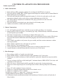
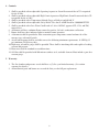
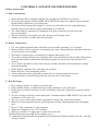
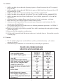
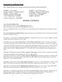
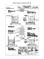
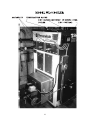
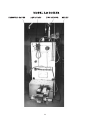
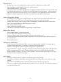
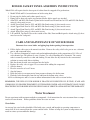
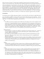
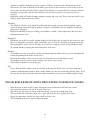
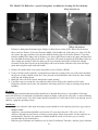
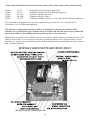
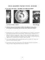
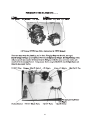
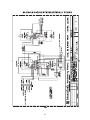
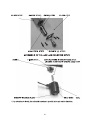
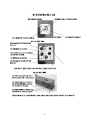
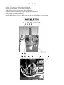
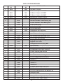
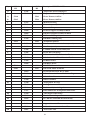
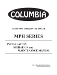
Columbia/Shenandoah®™
Waste Oil-Fired Boiler
Owner's Manual
WL-60 / L-24 Boiler
All Installations Must Be In Accordance With State and Local Codes and it is
the responsibility of the installer to assure all codes are met
For service, call your dealer or installer at:
or Columbia Boiler at (610) 323-2700 to find the distributor for your area
Date Installed: ____________________________
WARRANTY NOTICE
Use of Columbia Boiler Company equipment on equipment not manufactured or designed for use by
Columbia Boiler, VOIDS the warranty - property or personal damage could occur.
Sizing of the boiler is the responsibility of the purchaser.
A complete heat loss calculation for the structure or process is necessary to select the proper unit size.
Columbia Boiler Company
P O Box 1070
Pottstown, PA 19464 USA
TABLE OF CONTENTS
SUBJECT
PACKING LIST
SPECIFICATIONS WL 60 / L 24
BOILER CONTROLS
BOILER FLAME & BRICK INSTALLATION INSTRUCTIONS
PAGE
3
4-6
9
10-11
CONTROL LOCATIONS & PORTS WL 60
13
NOTES
17
CONTROL LOCATIONS & PORTS L 24
18-19
COIL INSTALLATION L24/WL60
20
BASIC BOILER & RADIANT HEAT INFORMATION
21
CABINET / JACKET ASSEMBLY
23
WATER TREATMENT
23-25
BOILER MAINTENANCE and MODEL 24 SWING DOOR OPERATION
26-28
BURNER / PUMP / CHIMNEY , AIR & OIL SUPPLY
28-34
ELECTRICAL / WIRING DIAGRAMS
34
START UP
40
BURNER MAINTENANCE
42
TROUBLE SHOOTING GUIDE
49
PARTS
51
APPENDICIES A/B : WARRANTIES
ATTACHMENTS : OEM CONTROLS INSTRUCTIONS
A/B
PACKING LIST
1 Boiler (coils installed if ordered)
1 Carton of cabinet panels
1 Temp/Pressure Gage
1 ASME Relief Valve (15 psi steam or 30 psi water)
1 Operating Aquastat w/ Thermowell or Steam Control
1 High Limit Aquastat w/ Thermowell or High Limit Steam Control
1 Low Water Cutoff w/ remote sensor (manual reset unless specified)
1 Water Level Gauge (glass) When boiler ordered as steam
1 Boiler Manual
1 3/4 X 1/2 FPT Swivel
1 Shenandoah Logo Label, white
1 Electric Junction Box w/ inner Bracket and Cover
1 Terminal Strip
1 Model Label (WL 60 / L 24) white
1 1/4 x 1/4 x 1/8 tee
1 1/4 NPT Hex Nipple
1 1/4 Nipple
1 1/2 Nipple
1 Suction Screen
1 Oil Filter w/ Gage
1 3/4 Check Valve
1 Vac/Air Gage
1 Oil Pump
24 Fire Brick
12 Split Firebrick (Model 24 series only)
1 Burner
1 Burner Swing Door (mounted)
1 Burner Cord (Quick Connect)
1 Boiler Cleaning Brush
1 Relay
3
COLUMBIA WL-60 WASTE OIL-FIRED BOILERS
Product Specifications
1. Boiler Construction:
1. Boiler shall meet EPA exemption guidelines for safe disposal (40 CFR 266) of used oil.
2. The boiler shall be ASME, I.B.R., ETLM approved and stamped to conform with the National Board of
Boiler and Pressure Vessel Inspectors.
3. The boiler shell and tubes shall be designed for burning #1, #2 fuel oil, used crank case oils, used
transmission, hydraulic and gear oils and any weight combinations up to SAE #50.
4. The cabinet shall be constructed of a minimum of 20 gauge galvaneal steel with a heat and
mar-resistant finish.
5. The boiler shall be of an inclined water tube design for self cleaning action.
6. Tankless coils shall be available and field replaceable.
2. Burner Construction:
1. U.S. and Canadian patented burner with slide out gun assembly providing a 36" oil preheat.
2. Burners shall be of the low pressure, air atomizing type using a thermostatically controlled combustion
air and oil preheat gun assembly.
3. The burner oil gun must have an automatic pre and post flame purge cycle.
4. The preheat assembly shall prevent overheating and over-pressurization of both air and oil. This design
must also limit internal carbonization and nozzle plugging associated with overheated fossil fuel
mixtures.
5. Access shall be provided to easily remove the gun assembly and allow routine maintenance without
removing the burner.
6. Burner shall be supplied to fire at the input rate specified.
7. Burner shall have a non-condensing exhaust.
8. Air for atomization must be designed to connect into an existing pressurized air source.
9. A quick disconnect cord shall be provided for electrical service to the burner.
3. Heat Exchanger:
1. Heat exchanger shall be of a multi water tube design.
2. Firing chamber shall be a welded construction with a minimum of 1/4" boiler plate.
3. Flame target area shall be refractory or brick and shall be replaceable. Replacement materials shall be
available.
4. The heat exchanger shall have welded multi path 2" minimum diameter ERW ASTM 176.66 tubes with
a minimum of 3/16 inch wall.
5. Three easy access, clean out panels shall be provided for exterior tube cleaning maintenance.
6. Must have a flame inspection port for visual inspection of flame without opening door or disturbing
draft.
7. Flue is 10" with a minimum 11 gauge connector.
8. Shall have a removable hinged burner mount for fire chamber access.
9. Shall have a minimum of (4) 2" washouts.
10. Shall have available a 4" supply and 3" return water connection.
11. Hinged Burner Extension factory attached to Boiler.
12. Combustion chamber modifications include field installation of firebrick on back wall and sides of
firing chamber.
4
4. Controls:
1. Shall be provided with an adjustable Operating Aquastat or Steam Pressuretrol that is UL recognized
for 8A at 120v.
2. Shall be provided with an adjustable High L imit Aquastat or High Limit Steam Pressuretrol that is UL
recognized for 8A at 120V.
3. Shall be provided with a Temperature/Altitude Gauge of 0-60 psi and 60-260° F.
4. Shall be provided with an adjustable Safety Relief Valve that is ASME listed for 1,000,000 BTU/H.
5. Shall be provided with a Low Water Cutoff rated at 5.8A at 120VAC, approved UL, CSA, and FM,
manual reset.
6. All burners will have cadmium flame sensors for positive, fail safe, combustion verification.
7. Burner shall have three indicator lights to monitor burner operation.
8. A thermostat shall be provided to allow convenient space temperature control and must be of the
mercury type with on/off switch.
9. An oil transfer pump shall be available to meet the following minimum requirements: 18 GPH @ 35
psi, minimum 1/4 hp heavy duty.
10. High range oil and air gauges shall be provided. These shall be interchangeable and capable of reading
vacuum and pressure.
11. Hour meter shall be standard to record burn time.
12. Oil filter shall be provided with 100-micron stainless steel, washable element. Must include a port for a
vacuum gauge.
5. Warranty:
1. The fire chamber and pressure vessel shall have a (5) five year limited warranty. (See written
warranty for details.)
2. All mechanical parts and burner are covered the first year for full part replacement.
5
COLUMBIA L-24 WASTE OIL-FIRED BOILERS
Product Specifications
A. Boiler Construction:
1. Boiler shall meet EPA exemption guidelines for safe disposal (40 CFR 266) of used oil..
2. The boiler shell and tubes shall be ASME, I.B.R., ETLM and stamped to conform with the National
Board of Boiler and Pressure Vessel Inspectors.
3. The boiler shall be designed for burning #1, #2 fuel oil, used crank case oils, used transmission,
hydraulic and gear oils and any weight combinations up to SAE #50.
4. The cabinet shall be constructed of a minimum of 20 gauge galvaneal steel with a heat and
mar-resistant finish.
5. The boiler shall be of an inclined water tube design for self cleaning action.
6. Tankless coils shall be available and field replaceable.
B. Burner Construction:
1. U.S. and Canadian patented burner with slide out gun assembly providing a 36" oil preheat.
2. Burners shall be of the low pressure, air atomizing type using a thermostatically controlled combustion
air and oil preheat gun assembly.
3. The burner oil gun must have an automatic pre and post flame purge cycle.
4. The preheat assembly shall prevent overheating and over-pressurization of both air and oil. This design
must also limit internal carbonization and nozzle plugging associated with overheated fossil fuel
mixtures.
5. Access shall be provided to easily remove the gun assembly and allow routine maintenance without
removing the burner.
6. Burner shall be supplied to fire at the input rate specified.
7. Burner shall have a non-condensing exhaust.
8. Air for atomization must be designed to connect into an existing pressurized air source.
9. A quick disconnect cord shall be provided for electrical service to the burner.
C. Heat Exchanger:
1. Heat exchanger shall be of a multi water tube design.
2. Firing chamber shall be a welded construction with a minimum of 1/4" boiler plate.
3. Flame target area shall be refractory or brick and shall be replaceable. Replacement materials shall be
available.
4. The heat exchanger shall have welded multi path 2" minimum diameter ERW ASTM 176.66 tubes with
a minimum of 3/16 inch wall.
5. Two easy access cleanout panels shall be provided for exterior tube cleaning maintenance.
6. Must have a flame inspection port for visual inspection of flame without opening door or disturbing
draft.
7. Flue is 9” with a minimum 11 gauge connector.
8. Shall have a minimum of (4) 1-1/2" washouts.
9. Shall have available a 4" supply and 3" return water connection.
10. Hinged burner door provided for fire chamber access.
11. Combustion chamber modifications include field installation of firebrick on back wall, base, and sides
of firing chamber.
6
D. Controls:
1. Shall be provided with an adjustable Operating Aquastat or Steam Pressuretrol that is UL recognized
for 8A at 120v.
2. Shall be provided with an adjustable High Limit Aquastat or High Limit Steam Pressuretrol that is UL
recognized for 8A at 120V.
3. Shall be provided with a Temperature/Altitude Gauge of 0-60 psi and 60-260° F.
4. Shall be provided with an adjustable Safety Relief Valve that is ASME listed for 1,000,000 BTU/H.
5. Shall be provided with a Low Water Cutoff rated at 7.4A at 120VAC, approved UL, CSA, and FM,
manual reset.
6. All burners will have cadmium flame sensors for positive, fail safe, combustion verification.
7. Burner shall have three indicator lights to monitor burner operation.
8. A thermostat shall be provided to allow convenient space temperature control and must be of the
mercury type with on/off switch.
9. An oil transfer pump shall be available to meet the following minimum requirements: 18 GPH @ 35
psi, minimum 1/4 hp heavy duty.
10. High range oil and air gauges shall be provided. These shall be interchangeable and capable of reading
vacuum and pressure.
11. Hour meter shall be standard to record burn time.
12. Oil filter shall be provided with 100-micron stainless steel, washable element. Must include a port for
a vacuum gauge.
E. Warranty:
1. The fire chamber and pressure vessel shall have a (5) five year limited warranty. (See written
warranty for details.)
2. All mechanical parts and burner are covered the first year for full part replacement.
WASTE OIL-FIRED BOILERS
SPECIFICATIONS SUMMARY
MODEL 24
MODEL 60
________________________________________________________________________
Waste Oil GPH (approx)
1.25 to 2.5
1.68 to 5.7
________________________________________________________________________
Gross BTUH Input (approx)
175,000 to
350,000 to
350,000 / hour
800,000 / hour
________________________________________________________________________
Gross
HP
4
to
8
6 to 20
________________________________________________________________________
Water Volume in Shell, Gallons
55
133
________________________________________________________________________
GPM Single Coil; Temp Rise 100 F
4.4 Max
6.5 Max
________________________________________________________________________
GPM (2) Coils; Temp Rise 100 F
x
13 Max
________________________________________________________________________
Width
w/o
Controls
Cab
27
32
________________________________________________________________________
Depth with Burner & Smoke Outlet
58
80
________________________________________________________________________
Height
57
63.6
________________________________________________________________________
Burner Model
B5
B5 Single or B10
Single
Nozzle
Dual Nozzle
________________________________________________________________________
Boiler Weight (dry) (approx.)
1,450
1,730
________________________________________________________________________
Total Shipping Weight (approx.)
1,800
2,475
________________________________________________________________________
Agency Listing (Operation, Safety, &
ETLM, ASME,
ETLM, ASME,
Performance)
IBR
IBR
7
BOILER ROOM REQUIREMENTS
A.
B.
C.
D.
E.
F.
G.
H.
Room should be well lighted and should have a source of emergency light.
Convenient water supply available for boiler and to clean the boiler room floor.
Unobstructed floor drains.
Since the combustion process requires a supply of air at all times, it is essential that provisions are made to
supply adequate air to the boiler room. This air supply is necessary to insure complete combustion, a clean
fire and to prevent nuisance shut downs due to excessively dirty burner parts. Air from the outside may be
provided through ducts, fixed louvers or motorized louvers.
Adequate space around the unit should be provided for inspection and service. We suggest 3 foot walkway
for service.
Do not allow your boiler room to become a “junk” room.
Provide 3” thick concrete pad for boiler (optional) or place on noncombustible surface.
Proper operation depends on adequate draft to maintain a negative pressure in the fire chamber. A
commercial draft inducer may be needed if natural draft is inadequate.
UNIQUE CHARACTERISTICS OF BURNING USED OIL IN A BOILER
A. Accumulation of ash produces numerous adverse affects:
1. Reduced heat transfer (U.S. Bureau of Mines) Research by the U.S. Bureau of Mines has determined
that 1/32-inch of soot coating causes 9.5% loss of boiler efficiency. The following table shows how
soot thickness effects efficiency
1/32-inch of soot
1/16-inch of soot
1/8-inch of soot
3/16-inch of soot
9.5% loss of efficiency
26% loss of efficiency
45% loss of efficiency
69% loss of efficiency
2. Reduced air flow also causes incomplete combustion
B. Conventional boilers are not appropriate for waste oil for the following reasons:
1.
2.
3.
4.
Improper heat exchanger design can not provide adequate gas exhausting.
Combustion chamber too small.
Water backed uninsulated combustion chamber condenses flue gas.
Poor accessibility for routine cleaning.
C. Shenandoah waste oil boiler features address all the problems
1.
2.
3.
4.
Heat exchanger designed to prevent ash buildup and achieve high transfer efficiency
Large access doors provide easy access for maintenance and cleaning
Refractory lined large combustion chamber produces high temperature combustion zone
Water tube design for efficiency, improved draft and minimal floor area used with its vertical design
8
Frequently Used Boiler Terms
BTU - British Thermal Unit, amount of energy to raise one lb. of water one degree F.
1000 BTU = 1 lb. of steam
34.5 lbs. steam/hr. = 1 boiler horsepower
240 BTU = 1 sq. ft. of steam
1 Gallon of #2 Oil = 140,000 BTU
1 Cu. ft. Natural Gas = 1,000 BTU
1 Therm. Natural gas = 100,000 BTU
150 BTU = 1 sq. ft. of hot water
1 Boiler hp = 140 sq. ft. steam radiation
34,500 BTU = 1 Boiler horsepower
1 Cu. ft. LP gas = 2,550 BTU
1 KWH = 3,413 BTU
BOILER CONTROLS
(Provided) Safety Relief Valve
Steam boiler gets (1) @ 15 psi/1,000,000 Btu limit relief.
Hot water boiler gets (1) @ 30 psi/1,000.000 Btu limit relief.
They are nonadjustable. Place on top of boiler in vertical position. Never reduce pipe size entering or exiting
the valve.
(Provided) Temperature/Altitude Gauge (temperature/pressure gauge).Mount in any convenient port. Typical
location is on front of boiler.
(Provided w/ steam boilers only) Water Level Glass - visibly allows water level to be seen. Mounts vertically
on upper left corner of boiler in (2) 1/2” ports.
(Provided w/ hot water boilers) M&M Model 750, Low Water Cutoff (LWC) This is a manual reset design.
5.8 Amp/115V protects boiler from low water levels that could cause boiler damage. Control has an alarm or
water feed switch (N.O.) between no’s 2 & 4 and a burner shut down switch (N.C.) between 5 and 2. The LWC
control box can mount anywhere near or on the boiler, and the remote sensor threads into any 3/4” port in
plates on front of boiler. Additional Model 767 or 764 float LWC may be ordered for special applications or
codes.
(Provided w/CWH & water boilers) L4006A Aquastat: Operating. 8.0 amp at 120 cycles burner to maintain
water temp in the boiler jacket. Mount in 3/4” port on front of boiler.
(Provided w/CWH & water boilers) L4006E Aquastat: High limit (has manual reset button). 8.0 Amps/120V,
shuts down burner if operating aquastat fails. Do not set above 200 or risk steam formation in water boilers.
Mount in 3/4” port on front of boiler.
(Provided w/steam boilers) L404A Operating Pressuretrol. 2 to 15 psi, 1 to 6 psi differential, 8 Amp at 120 V,
SPST. Cycles burner to maintain steam pressure in the boiler. Mount above boiler using 1/2” or 3/4” port.
(Provided w/steam boilers L404C) High Limit Pressuretrol: Manual reset, 2 to 15 psi, 8 Amps 120V, SPST.
Shuts down burner if operating control fails Mount above boiler using 1/2” or 3/4” port.
(Provided w/ steam boilers only) Warrick 26C1D1C Low Water Cutoff (LWC) with probe and manual reset,
26K sensitivity, 120VAC, NEMA1, normally closed push button. Additional Model 767 float LWC or
M&M42S LWC/Pump Control may be ordered for special applications or codes.
9
Items Not Provided That Should be Considered: Pressure Reducing Valve - used to automatically maintain
a desired pressure in the system, acts as a make-up water supply. Tempering Valve - allows hot water from
boiler to accurately mix with returning cool water to make desired water ready to go to the application. The hot
water should be at least 20 degrees warmer than the return water for smooth operation. Water Circulator used to circulate boiler water. Expansion Tank - used to absorb expanding water when heating it.
Water and Flame Locations In Boilers
10
Brick Lining Location In WL 60
11
Model WL60 Boiler Connection Ports
(Port, Quantity, NPT, Suggested Uses *)
A
B
C
D
E
F
G
H
I
(3)
(4)
(3)
(1)
(4)
(1)
(1)
(1)
(4)
1/2”
3/4”
1”
1-1/4”
2”
2-1/2”
3”
4”
1”
Water level glass, make-up water inlet
Aquastats (water), Controllers (Steam), 750 LWC probe
Relief Valve, pr./temp gauge
Relief Valve (alternate)
Drains or Alternate Returns
Optional 764, 767 LWC
Primary return water or condensate
Heated water or steam to application
Optional tankless coil(s) w/boilers, std. w/CWH
Model L24 Boiler Connection Ports
(Port, Quantity, NPT, Suggested Uses *)
A
B
C
D
E
F
G
H
(3)
(3)
(3)
(4)
(1)
(1)
(1)
(2)
1/2 “
1/2"
1”
1-1/2”
1-1/4”
2-1/2”
4”
1”
Water level glass, make-up water inlet
Aquastats (water), Controllers (Steam), 750 LWC probe
Relief Valve, pr./temp. gauge
Return water or condensate
Relief Valve, (alternate)
Optional 764, 767 LWC
Heated water or steam to application
Optional tankless coil w/boilers, (upper rear of boiler)
* Note that the above is suggested uses of the ports. As can be seen in our photos there are
many acceptable ways to install the piping and controls. An experienced plumber and controls person should be used to assure the design is functional and meets needs. One must
allow for initial cleaning and purging of oils and dirt from the water loop and then refill
and treat the water as needed to preserve boiler life. Read all the following pages carefully
and plan plumbing and control locations before starting.
12
13
14
15
16
Notes
17
18
PRESSURE GAUGE
AQUASTATS
LWC SENSOR
19
ELEC. BOX
COIL INSTALLATION
Note the Model L24 can accept just one coil, the Model 60 can utilize one or two.
Coil Installation:
Model L24: The front cover plate and rubber gasket on the boiler needs removed first.
The coil can be inserted in the boiler after the plate is removed.
The coil is attached at the rear of the boiler.
Remove the (2) “dummy” fittings from the rear outside of the boiler.
Slide the coil ports through the (2) open ports in the rear of the boiler.
The coil is attached to the rear wall of the boiler with the two special fittings.
Replace the front plate and rubber gasket on the boiler.
Model WL60: coil(s) attach to the front plate(s).
Remove and replace the front plate(s) and rubber gasket(s) on the boiler to add coils.
Coil Removal:
Reverse the directions for installing a coil.
Contact your dealer if you need “dummy” fittings for the Model L24 to plug the two holes.
Coil Gasket Replacement:
1. Remove the old gasket and thoroughly clean the boiler surfaces and the plate surfaces.
2. Place the new gasket over the boiler studs making sure that it fits evenly.
3. Using the correct size socket wrench, tighten the nuts snug but not over crank them. If the gasket leaks
while the pressure is being brought up on the boiler, tighten the nut only enough to stop leaking.
4. Check your gaskets for leakage for the next three days after installation and if leakage is detected
tighten only enough to stop it.
5. Excessive tightening will flatten out the gaskets to a point where they will no longer be able to seal.
Please do not tighten more than is required to seal.
20
Basic Information for a Boiler System
Water [properly treated] is the most common fluid used in a closed loop hydronic system.
Other Fluids Used in Closed Loop Systems
• Glycol (antifreeze) is used in systems where below freezing or above boiling point temperatures may be
reached.
• Ethylene glycol - toxic and less heat transfer efficiency. Do not use with tankless coils.
• Propylene glycol - nontoxic and better heat transfer efficiency.
• An Inhibited (formulated to minimize corrosion) form of glycol is best choice.
• Oxygen in water leads to rust. Chromate removes oxygen from water, but Chromate use is banned in
some areas. Do not mix Chromate solutions and antifreeze solutions.
• 100% antifreeze is wasteful and not the best heat transfer design.
• 30% - 50% antifreeze is typical.
• Galvanized piping is not desirable, use PEX O2 barrier, black, or stainless steels.
*Always have a qualified water quality technician establish proper water conditions in
your system. Mistakes could cause the boiler/system to prematurely fail….very costly repairs.
Circulating the Hydronic System
• Optimum comfort is obtained with constant circulation of water at a temperature just equal to offset the
heat loss. This is obtained with 2-stage thermostats, a circulator, and valves. This method is capable of
reducing operating costs by 25% over simple on/off systems.
• Combustion and heat transfer is optimum when the system runs continuously, thus an oversized boiler
will be slightly less efficient.
• Expansion/contraction (pipe stress) is minimized with continuous circulation.
• 80 to 100 degree F water may be circulated to the radiant floor. A floor too warm is uncomfortable thus
the water temperature is kept to a minimum.
• Steel boilers can withstand thermal shock from cool return water but internal sweating could occur even
when the burner is firing. Water temperature returning to the boiler of 140 degrees or greater is best.
• Controls and valves should be used to allow the boiler to operate as warm as possible and the
circulating water in the floor to regulated to a lesser temperature.
• Circulator is a pump to move water through the boiler or associated process.
• Circulator should pump away from the expansion tank. Pumping toward the tank can lead to air
problems by creating unwanted flows, pressures, or venting may occur.
• Circulators will last longer running continuously.
Tankless Coils
• A tankless coil is a bundled length of tubing inserted in the boiler water and used to heat domestic
water. This water is used for sinks, showers, car washes, food processing...
• Typical coil material is copper with fins or other surface area increasing design.
• Water passing through coils is kept separate from the treated water in the boiler jacket.
• High mineral water will plug a coil over time requiring cleaning to operate efficiently.
• Rating methods for coils ( gallons per minute at a specific temp rise): Intermittent - for non steady
water flow applications through coils. Continuous - steady water flow without chance for boiler to
recover.
• Circulating to a separate insulated storage tank will allow extra water volume to meet peak loads and is
likely a better option than buying a larger boiler system.
21
Expansion Tank
• Heating water causes it to expand, thus creating a need for a expansion or overflow tank.
• If the expanding water is trapped it will create unsafe pressures.
• Tanks should be rated 75 psi or greater.
• Two styles of tanks are available on the market: Diaphragm, bladder inside that can be pressurized with
air. Size this tank capacity to be 9 gallons for every 100 gallons of water in system. Non-pressurized
tank, basic open interior. Size this capacity to be 15 gallons for every 100 gallons of water in system.
• Antifreeze solution expands 20% more than water. Expansion tanks must be sized larger.
Indirect Storage Water Heating
• An auxiliary water storage tank, usually insulated, that simply stores hot water from the tankless coil.
The boiler keeps this tank “ready” by re-circulating the water to the coils for reheating.
• Auxiliary water storage creates a larger volume of immediately available domestic hot water for the
times when a coil would not be able to keep up on it’s own.
• It is a energy efficient system.
• Simple installation used with a boiler.
• Cost effective compared to installing a bigger boiler to meet demand.
Radiant Floor Heating
• Greater human comfort vs. forced air heating.
• Even air temperatures through elevation in room.
• Cleaner, no dust blowing. Used in paint shops and other dust sensitive areas.
• Concrete floor thermal mass allows quicker temperature recovery in heated space if doors or bays are
opened frequently.
• Better zoning control.
Tubing for In-floor Heating
• Carries water to areas needing heat. Three styles are commonly used: Metallic, soft copper typical.
Synthetic, rubber and plastics. Composite - laminates of metal and synthetic.
• Synthetic - most popular. Could be of rubber, polyethylene, or polybutylene.
• Oxygen Permeation - oxygen entering the circulating system through the tubing walls causes premature
failure of components due to rusting. Tubing with oxygen barriers is available through contractors.
• Do not be thrifty on tubing, it can not be easily repaired or accessed if done incorrectly or is of a type
that allows oxygen to enter the water loop.
Snow Melting
• Anti freeze solutions must be used in the circulation system going outdoors.
• A second heat exchanger should be used to keep the boiler water loop and ice melt (antifreeze) loop
separate.
• Put a sensor in the outdoor concrete slab to keep the surface of the slab at 34 degree F.
• Snow or ice is unlikely when temps drop below 10 degrees F or are above 40 F so design the controls to
give the boiler the day off.
22
BOILER JACKET PANEL ASSEMBLY INSTRUCTIONS
*Model L24 will require that the lower part of cabinet front be snapped off at perforations.
1.
2.
3.
4.
5.
6.
7.
8.
9.
Model WL60 and L24, mount burner on boiler swing door.
Do not pipe the boiler until cabinet panels are on.
Piping can be done only on the top portion of boiler before panels are attached.
Stand L.H. and R.H. Side Panels against boiler Attach Lower Front Panel to L.H. and R.H. Side Panels
using (6) sheet metal screws.
Attach Lower Back Panel to L.H. and R.H. Side Panels using (6) sheet metal screws.
Attach Upper Back Panel to L.H. and R.H. Side Panels using (4) sheet metal screws.
Attach Upper Front Panel to L.H. and R.H. Side Panels using (4) sheet metal screws.
Attach Joiner Plate using (2) sheet metal screws.
L.H. and R.H. Top Panels fit over the outside of the Side, Front and Back panels. Attach using (5) sheet
metal screws for each panel.
CARE AND MAINTENANCE OF YOUR BOILER
You must clean a new boiler and piping loop before putting it into operation.
1. Fill the boiler with water to the normal waterline. Remove the safety relief valve port or use a alternate
port to add compound below.
2. Use a boil-out compound of caustic soda and trisodium phosphate in the proportions of 2-1/2 lbs. of
each chemical per 120 gallons of water. Caution: Use care in handling these chemicals. The caustic
soda is extremely corrosive to skin and clothing. Do not allow the dry material or the concentrated
solution to contact with skin or clothing.
3. Mix the chemicals with water and pour into the boiler.
4. Replace the safety valve & pipe if it was removed for adding the compound.
5. Start the burner.
6. Heat the water for at least 5 hours.
7. Stop the burner.
8. Drain the boiler in a manner not to burn persons or damage the boiler room.
9. Flush the boiler thoroughly from the top and from the bottom using a hose.
10. Re-seal drain ports and see water treatment information for hot water or steam boilers.
REMEMBER, THE LIFE OF YOUR BOILER IS DRASTICALLY REDUCED BY SLUDGE, SCALE AND
CORROSION. BY PROPER TREATMENT OF THE BOILER WATER AND SYSTEMATIC BLOW DOWN
PROCEDURES YOUR BOILER WILL PROVIDE YEARS OF SERVICE AND MAINTAIN THE WARRANTY.
Water Treatment
Do not experiment with treatment methods or compounds. Seek instructions for water treatment from a competent local water chemist. Follow guidelines below for water or steam.
Water Boiler
At start-up, hot water boilers should be filled with water, vented, and brought to operating temperature to
ensure that all air is removed from the system and the boiler. Failure to bring the system to temperature can
result in serious system and boiler damage.
23
Hot water boilers are subject to serious damage and failure if leaks develop in the hydronic system that
requires excessive make-up water. The make-up water introduces high levels of oxygen which will lead to corrosion and component or system failure in a very short time. All boilers and systems should be checked for
leaks on a frequent basis. Leaks may be indicated by standing water under or around system components, rust
spots or drip spots. On a weekly basis, the system should be checked for hidden leaks. This is done by shutting the make-up water supply isolation valve at a time when the burner is not operating. If pressure on the
boiler pressure gage falls, it is an indication that there is a leak in the system which should be located and
repaired immediately. Open the make-up water isolation valve after completing the test. Proper start-up and
verification that hot water boilers are leak free on a weekly basis is adequate to protect the hot water boiler.
Steam Boilers
Steam boilers operate at higher temperatures and have a steam region that can be subject to rapid failure due to
poor water quality. In addition, system operation can be adversely affected by poor water chemistry. The following terms and guidelines are for reference. Seek the advice of a water treatment specialist to best suit your
application. Use only chemicals approved in your locality/state.
PH
• The PH factor is the most important factor influencing scale forming or the corrosive tendencies of the
boiler water. It should be adjusted to between a minimum of 10.5 and a maximum of 11.0 to prevent
acidic corrosion of the boiler tubes and plates and to provide for the precipitation of scale forming salts.
• Below a PH of 5.0, the water is acidic enough to dissolve the steel boiler plates. Under these conditions, the steel gradually becomes thinner and thinner until its destruction. At a PH between 5 and 9.4,
pitting of steel plates will occur at a rate depending on the dissolved oxygen in the boiler.
Dissolved Oxygen
• Dissolved oxygen is caused by the solubility of atmospheric oxygen into the supply water. Aeration of
city water supply is frequently used to remove other noxious gasses. Efficient aeration results in
saturation of the water with oxygen.
• The majority of corrosion problems are directly related to the quantity of dissolved oxygen in the
boiler water. Elimination of the corrosive effects of dissolved oxygen can be accomplished both
directly or chemically.
• Dissolved oxygen: Direct (mechanical removal) or chemical (using additives) removal of the oxygen is
done through mechanical venting valves or the introduction of specific chemicals in the boiler to react
with the oxygen. The dissolved oxygen content should be maintained at a minimum but at no time
should it exceed 0.007 mg/l.
Sulfites
• Sodium sulfite is generally used for the chemical removal of dissolved oxygen within the boiler water.
To assure the rapid and complete removal of the oxygen entering the boiler feed water system the
concentration of sulfite in the boiler must be maintained at a minimum of 20 p.p.m. (parts per million)
Solids
• Solids can be broken up into two categories of either suspended and dissolved. Suspended solids are
those which could be removed by filtration while dissolved solids are in solution with the water.
• The best test for the determination of solids content of the boiler water is through a conductance test.
The conductance value of boiler water varies by the various ionized salts present. The conductance can
be used to measure the total dissolved solids in the boiler water and to serve as an accurate means for
the control of solids through the use of blow down.
24
•
•
Another test which is sometimes used as a gauge of solids is to measure the chloride present in the
boiler water. The ratio of chlorides in the boiler water to that of the feed water can be used as a means
to determine the amount of blow down required. The chloride test is unsuitable for feed water with low
incoming concentrations and the concentrations in the feed water must be averaged over time for
accuracy.
High boiler solids will lead to foaming, priming, surging, and carry over. These items may only be over
come by proper blow down of the boiler.
Alkalinity
• The alkalinity of boiler water should be sufficiently high enough to protect shell and plates against
acidic corrosion, but not that high to produce carryover. A minimum value for alkalinity for adequate
protection is 200 p.p.m.
• High boiler alkalinity in excess of 700 p.p.m. should be avoided. Values higher than 700 can lead to
embritlement of the steel.
Phosphates
• Phosphates are used to react with calcium hardness in the boiler water. In order for this reaction to take
place it is important to maintain a Ph at a minimum value of 9.50. It is desirable to keep the concentration of phosphates in the water to 30-50 p.p.m. in order for complete reaction of the phosphates with
the calcium hardness entering the boiler through the feed water.
Hardness
• The hardness of water is caused by calcium and magnesium ions which will vary greatly throughout the
country depending on the source of the water.
• In boilers the hardness of the water can cause the formation of scale and sludge or mud.
• The hardness must be removed in the makeup water to the return system.
• Total hardness should not exceed 50 p.p.m.
Oils
• Every effort should be made to prevent oils from getting into the boiler water. Oil causes foaming or
combines with suspended solids to form a sludge which can cause the overheating of boiler plates. If oil
does get into the boiler, the boiler should be taken immediately out of service and thoroughly cleaned.
STEAM BOILER BLOW DOWN PROCEDURE TO REMOVE SOLIDS
•
•
•
•
•
•
Blow down can be done in the evening after burner has been shut down and water has settled
Open boiler blow down valve for 30 seconds, then close.
Open float type low water cut off or feeder blow down valve for 30 seconds, then close.
Now go back to the boiler blow down valve. Open and close the valve quickly, three times
Repeat this procedure with the low water cutoff or feeder valve
This should rid the boiler of most precipitated solids
25
System Maintenance
O Disconnect all incoming electrical power prior to servicing controls, pumps, or burner.
O Use extreme caution around boiler piping since it may be hot.
O The life of your boiler can only be measured by the care given to it by those who are charged with the
responsibility of boiler maintenance. A log book of the following items should be maintained in the
boiler room at all times.
Daily maintenance list
•
•
•
•
•
Check operating pressures of water/steam, oil, and air.
Check operating temperatures.
Observe condition of flame.
Check boiler water is at its proper operating level.
Steam Process Boiler Only Blow down the boiler and low water cut off feeder (if equipped)
Weekly maintenance list
•
•
Check fuel supply for leaks.
Observe operation of circulating pump(s).
Monthly boiler check/maintenance list
•
•
•
•
•
•
•
•
•
•
•
Safety relief valve - pull lever and confirm flow escapes.
Inspect / Flush Oil filter and suction screen if oil flow appears to be obstructed
Test operating and hi-limit controls and flame detection device.
Check boiler room floor drains for proper operation.
Inspect combustion air inlets of boiler room.
Clean ash from inside boiler’s heating surfaces and chimney. Frequent cleaning will extend boiler life.
Ash produces acids harmful to metals and prevents clean combustion
Check draft in chimney.
Test low water cut-off.
Check coil plate seals, gaskets, and piping for leaks.
Check tempering valves, expansion tank, and secondary heat exchangers.
Steam Heating Boiler Only Blow down the boiler and low water cut off feeder (if equipped)
Cleaning the Flue Passages
Under normal operating conditions the flue passages will need to be cleaned. If excessive soot has built up on
the flue passages they can be cleaned following this procedure.
1. Turn burner power off to prevent accidental burner firing. Remove the front cleanout door(s) and open
burner door. The WL-60 door will swing open simply by removing the 3 hex nuts on the handle side of
the door. If burner is hard piped, disconnect pipe fittings to allow door to swing freely. The L-24 has a
slightly different procedure. (see below) Care must be taken when removing these cleanout doors not to
damage the insulating millboard gasket.
26
The Model L-24 Boiler has a special swing door assembly for cleaning the fire chamber.
Hinge bolt and nut
Hinge bolt and nut
If burner is hard piped, disconnect pipe fittings to allow door to swing freely. Insure that the burner
door is not hot. Remove 2 hex nuts from the middle of the handle side of the door. (see above left) Do
not remove the upper and lower hex nuts that hold the burner plate on the boiler. Remove 2 hex nuts
from the middle of the hinge side of the door. (see above right) Do not remove the upper and lower hex
nuts that hold the burner plate on the boiler. Loosen the 2 hex nuts located on the door hinge bolts (see
above right) just enough to allow the door to pull away from the boiler. This will provide enough
clearance for the door to pivot on the bolt hinges and clear the boiler. Pull door away from the hinge
point and swing door open with side handle.
1. Remove the smoke hood access panel and gasket on rear of boiler. (WL60)
2. Using a flat flue brush, brush the accumulated soot and scale starting in the rear of the boiler brushing
the top row of tubes and the crown sheet first, proceed to brush down the tubes from the front starting
at the top and working down.
3. Brush the side wall of the firebox through the burner opening.
4. Carefully scoop or vacuum the soot and scale which is now lying in the chamber of the boiler.
Refractory material can become soft and brittle after firing and can be subject to damage from harsh
handling.
Draining
A clean, properly maintained heating boiler should not be drained unless there is a possibility of freezing,
unless the boiler has accumulated a considerable amount of sludge or dirt on the water side, or unless draining
is necessary to make repairs. Very little sludge should accumulate in a boiler where little to no makeup water is
added to a properly operating system.
Antifreeze
•
•
•
Antifreeze solutions when used in heating systems should be of the ethylene glycol base type with an
inhibitor added.
Antifreeze concentrations should be not less than 33% nor more than 66%. The service life of
antifreeze depends on such factors as heating system design, hours of operation, aeration and rates of
contamination. Therefore, the antifreeze solution should be tested at least once per year and as
recommended by the manufacturer.
Ethylene glycol solutions are harmful or may be fatal if swallowed. Therefore, ethylene glycol solutions
27
•
should only be used in closed circulating systems without tankless coils. Propylene glycol should be
used in boilers that have tankless coils installed.
Antifreeze solutions expand more than water for a given temperature rise. Allowance must be made for
this additional expansion when antifreeze solution is used in the heating system.
Fireside Corrosion
•
•
Some fuels contain substances which can cause fireside corrosion. Sulfur, vanadium and sodium are
among the materials which may contribute to this problem.
Preventing this trouble from this source depends greatly on keeping the boiler heating surfaces dry. It is
recommended to eliminate this problem that the boiler water temperature be maintained at 140 degrees F
minimum year round and that the input is adjusted that a minimum stack temperature of 400 degrees F
is maintained.
Sealants
•
Sealants may have a detrimental effect on boilers, pumps, relief valves, etc. and are not recommended
to be used in hot water heating boilers.
BURNER, PUMP, & CHIMNEY
PUMP SPECIFICATIONS
'A' Pump
1/4" FNPT
1/8" FNPT
40-60 PSI
6 GPH
1725 RPM
1/4
CW Shaft End
20î Hg
10í Vertical
3/4" pipe
1" pipe
Inlet Port
Outlet Port
Pressure Range
Max. Flow
Speed
HP
Rotation
Max Operating Vacuum
Maximum Suggested Lift
Horizontal Suction Piping < 30 Ft.
Horizontal Suction Piping > 30 Ft.
'J' Pump
1/2" FNPT
1/4" FNPT
20-40 PSI
18 GPH
1725 RPM
1/4
CW Shaft End
20" Hg
10' Vertical
3/4" pipe
1" pipe
INTRODUCTION
Purchase of a Coulmbia/Shenandoah waste oil boiler is a wise investment. To maximize the return on this
investment you must read and save this manual. It contains installation instructions, diagnostic procedures, burner cleaning, maintenance procedures and parts ordering information. Follow the installation
instructions carefully.
You can expect years of reliable performance with a properly installed and maintained system.
THIS BURNER IS INTENDED FOR COMMERCIAL USE!
The burner shall be installed only by a qualified installer, one who is engaged in, responsible for or
thoroughly familiar with the permitting, installation and operation of oil-fired appliances; who is
experienced in such work and is familiar with the precautions required; and who will comply with all the
requirements of the Authority having jurisdiction over the installation.
The installation of equipment in the United States must consider the requirements of the following publi28
cations of the National Fire Protection Association, Battery March Park, Qunicy, Massachusetts 02269:
N.F.P.A.
N.F.P.A.
N.F.P.A.
N.F.P.A.
N.F.P.A.
No. 30
No. 31
No. 88A
No. 88B
No. 211
Flammable and Combustible Liquid Codes
Standard for Installation of Oil Burning Equipment
Standard for Parking Structures
Standard for Repair Garages
Standard for Chimney, Fireplaces, Vents and Solid Fuel Burning Appliances
The installation of Equipment in Canada must consider the requirements of C.S.A., Standard B 139,
Installation Code for Oil Burning Equipment.
This burner is recommend for burning #2 fuel oil, used motor oil, automatic transmission fluid,
hydraulic oil, vegetable oil and gear oil mixed not to exceed 50 SAE. Such oils may contain gasoline and
specific precautions on the handling and storage of waste oils are to be observed.
Do Not add to oil supply or burn: unknown garbage oils, gasoline, naptha, chlorinated cleaning solvents or oil
additives in this boiler. It is not unusual to experience operating problems such as plugged nozzles, suction
line leaks, etc. during start up and initial operation. Follow start up instructions for purging fuel and air lines to
help avoid these problems.
BURNER COMPONENTS IDENTIFICATION
AIR REGULATOR (COMPRESSED AIR)
29
FIELD ASSEMBLY INSTRUCTIONS - BURNER
1) PRIOR TO INSTALLING BURNER, CHECK FOR SHIPPING DAMAGE TO
FLAME RETENTION HEAD AND IGNITION ELECTRODE ALIGNMENT.
2) If components are not as shown you can make adjustments to the electrodes by removing the
hole plug on top of burner tube near mount flange. With screw driver, loosen the screw
holding the electrode clamping plate. Adjust electrodes as shown. Re-tighten clamp screw.
Do not over tighten or insulation on electrodes may crack. Examine electrode position after
tightening to be sure position has not changed. Replace hole plug.
3) The electrodes should not touch surrounding metal parts or be within 3/16” as they will
short the arc and not light the oil spray.
4) Attach burner to boiler door. Grasp burner by the mount flange and motor, slip burner’s
flange over studs on hinged burner door and secure with nuts.
30
INSTALLATION OF CHIMNEY SYSTEM
INSTALL CHIMNEY TO FLUE COLLAR OF BOILER OR HEATER
1) Select a location for your boiler observing minimum clearance to combustibles. Consider that maintenance
and cleaning will be required. Allow adequate work space around burner and stack.
2) For best operation minimize distance of horizontal chimney runs. Do not exceed 8' in length. Horizontal
runs must have a 1/4" rise per foot. Clean horizontal runs every 500 hours of use or as needed. Ash will
accumulate here and block draft. Poor draft causes poor flame, backpressure, oily buildup, unreliable
ignition.
3) WASTE OIL BOILERS ARE DEPENDENT ON PROPER DRAFT FOR EFFICIENT BURNING.
ASSURE THAT ADEQUATE MAKE-UP AIR IS AVAILABLE. NEGATIVE DRAFT REQUIREMENT: -.04 TO -.06 INCHES MIN. OF WATER COLUMN AT BOILER OUTLET. BUILDING
EXHAUST FANS OR COLD BUILDINGS AT NIGHT CAN REVERSE YOUR DRAFT AND
CAUSE FUMES, POOR COMBUSTION, OR NUISANCE BURNER LOCKOUTS. TAKE
MEASURES TO ASSURE BOILER WILL HAVE PROPER DRAFT DIRECTION WHEN OPERATING. * CHECK DRAFT AFTER START-UP AND STEADY STATE. THEN CHECK BY OPEN
ING DOORS AND STARTING VENT FANS TO ASSURE THAT DRAFT REGULATOR CAN
MAINTAIN -.04 TO -.06 MIN. UNDER ALL CONDITIONS. A SECOND REGULATOR MAY BE
NEEDED IF DRAFT CAN NOT BE MAINTAINED. IT MAY BE NECESSARY TO INCREASE
DRAFT TO -.10 INCHES OR HIGHER TO ACHIEVE FULL FIRING RATE WITH THE B-10
BURNER. CONSULT FACTORY OR DISTRIBUTOR FOR ASSISTANCE.
4) If permanent masonry chimney is not available, use appropriate diameter multi-wall manufactured chimney
and collars listed for use with oil fired boilers per UL 103 or All Fuel Class A. Locate for easy connection to the boiler and install per manufacturers' instructions and local building and fire codes. Normal
operation will produce a gross chimney temperature between 500F and 800F when boiler is clean.
5) The chimney must extend a minimum 3' above the highest roof line within 10'. In general you will
need a minimum of 2 feet of vertical for each foot of horizontal for best draft.
6) Use a stack that is equal diameter to the boiler outlet. Use minimum 24 gauge single wall connector pipe
between boiler outlet and damper. Do not allow rain to come down the chimney and have a path into fire
chamber. This will create a rusting environment. Install a chimney tee near the boiler to act as a cleanout /
water trap.
7) Locate barometric damper / draft regulator (REQUIRED) near the boiler. Its opening must be visible
from the floor and be isolated from strong airflow that could falsely affect its ability to regulate. Read
instruction sheet included with damper. A draft inducer can be used to overcome poor draft conditions and
should be placed as close to the roof or wall as possible. Inducers will pull air better than push it. A
Grainger 4C732 or larger is suggested. Smaller inducers will not be strong enough in some chimney
installations.
31
COMPRESSED AIR SUPPLY
1. A minimum 2 CFM at 40 psi is needed into the B-5 single burner and 4-5 CFM @ 40 psi for the B-10
double burner. Use a hydraulic quick disconnect or put ample flex in the line to swing burner open when
servicing. A dedicated air compressor at the boiler in lieu of using the shop’s air system is acceptable. A
compressor of 3/4 to 11/2 HP is typical. Consult your installer for models available. Drain all compressors
frequently to help keep moisture from entering burner.
2. Many burner service problems are from “rusty” air causing burner components to fail. It is wise to use a
oiler and/or regulator to treat & reduce air pressure entering the burner to approximately 60 psi. Wear on
burner parts will be reduced and ignition more reliable. Providing a drip leg with valve near the burner to
trap water, scale, and rust is also a good idea. If water is present take all measures to remove it. The air
solenoid may stick and other components may rust and fail.
3. SERVICE TIP: 80% of service problems can be avoided by keeping contaminants like rust chips, water,
pipe dope, insects from reaching burner through the air and oil lines.
OIL PUMP MOUNTING
1. Consult your dealer for best plumbing methods before starting. Mount the pump as near the oil supply tank
as possible. You may mount the pump above the tank to suction lift oil to the pump or another option is to
place the pump below the tank level to gravity feed or siphon oil to the pump. Do not exceed 10 psi into
the pump inlet in any arrangement or the seal may leak. Allow space for service. Be sure to meet all
building and fire code requirements.
2. Any pump/motor orientation is acceptable as long as the pump shaft is horizontal. You may rotate the
pump head on the mount to simplify plumbing connections. Be sure the motor and pump shafts are aligned
and coupling set screws are tight before operating.
Above Tank Mount
Below Tank Level Mount
32
33
Suction Line: Field provides piping from Check Valve to Filter. Secure piping to keep the Suction Strainer 6
inches off the bottom of the tank in order to avoid water and antifreeze pickup from the bottom of the oil tank.
Plan ahead for routine service of components. Use minimal number of fitting to reduce chances of suction
leaks. Note: Some J Pumps have dual suction ports. It is only necessary to pipe to one of these 1/2 inch ports.
Pressure Line (Oil Pump Outlet): After the provided Nipple/Tee/Gauge the field provides tubing or piping to
reach from the 1/4 Tee to the 1/2 Valve near the Burner. A 3/8 inch or 1/2 inch FLARED (never use compression) soft copper tubing is commonly used. Hard metal tubing or metal pipe is acceptable but may incur more
cost, has more potential for leaks, and is not flexible to swing the burner open for routine cleaning. Consult
your dealer on sizing for your application.
Try to avoid high spots in the oil piping or looping the line above the burner as this creates a trap and collects
air. Collected air will delay the oil getting to the nozzle, causing a weak flame, slow or failed ignition, or
pressure gauge and flame pulsation.
[ TIP: Spiral some excess tubing at the burner to allow the burner door to swing open w/o having to disconnect the oil line tubing. ]
Do not connect oil line to valve at the burner until after the oil line is purged of dirt and air.
[Suggestion: To ease future oil line purges, adding a tee and drain cock near the burner allows dirt and
air to be purged without disconnecting the line from the burner.]
ELECTRICAL CONNECTIONS
All electrical wiring must meet National Electrical Code, N.F.P.A. #70 for BOILERS installed in U.S., and
C.S.A. Standard C22.1, Canadian Electrical Code, Park 1, for Canada.
Install a panel mounted breaker for single phase 115V 15 AMP grounded service. Run minimum of 12 gauge
wire in metal conduit. Do this with the power still “OFF.” TIP: If the main 15 amp breaker is far from the
burner, installing a manual switch or breaker near the burner may be required by code. It is also handy for
cutting main power in an emergency or for servicing.
The burner cord has four wires: Black is power to burner. White is neutral. Red is power out from
burner to oil pump or accessories. Maximum 10 amps total load. Green is ground.
For field wiring of oil pump and accessories use minimum 16 gauge wiring.
*Be sure to wire burner and controls so that the burner always has power. This allows the heating
elements to keep the block warm and ready for the next start up. WIRE OPERATING AQUASTAT TO
T-T TERMINALS ON THE BURNER. DO NOT WIRE LIKE A TRADITIONAL OIL BURNER.
34
35
36
37
B10 DUAL NOZZLE BURNER INTERNAL WIRING
38
39
INITIAL START UP AND OPERATING SEQUENCE
1. Check secondary air settings as described in section #3 on page 41. Place the 3-position toggle switch on
the Burner to “OFF.” Energize the boiler circuit with electricity. The amber and red lights on the slide gun
will come on. Flip the 3-position toggle switch on the Burner to “PRIME.” The pump will start. Open the
bleed valve on the pump to relieve air, have a shop towel ready, after a few minutes there will be oil and air
sputtering from the bleeder. Close the bleeder when oil runs free of air. Oil will now start filling the line
to the burner.
2. Since the oil line is not attached to the burner yet have a bucket ready to catch oil, but be patient. It may
take 5-10 minutes to prime the pump and get oil to the burner. Minimize wear on pump and time involved
by filling oil lines and filters with oil before running pump.
3. Once the line is filled you will start catching the contaminated oil at the burner in your bucket. When the
oil is free of air and debris run another few gallons more and close the purge valve or connect the oil line to
burner. Flip the 3-position toggle switch on the Burner to “RUN.”
4.
By now the red light indicating preheating of the oil may have gone off. If it has, turn the operating
aquastat to a setting higher than boiler water temperature. The burner will start.
5. The fuel pump starts and the air solenoid valve opens to allow air into the air tank and air proving switch.
When air pressure of 20 psi is achieved in the tank, the air proving switch closes providing power to burner
motor and oil solenoid valve. The burner will attempt to fire and the green light comes on indicating the
burner is firing.
6. Adjust B-5 burner oil pressure to 2-5 psi or B-10 burner 3-7 psi oil pressure. Fine tune pressure setting
based on the instructions on the following page.
7. Adjust air pressure regulator on burner to approximately 12-14 psi on a B-5 single nozzle burner and 15-17
psi on a B-10 dual nozzle burner. The preheated oil and air are mixed at the nozzle and the fuel is
atomized as the electrodes arc for ignition. The red light will cycle on/off to automatically maintain air/oil
temperature.
8. Adjust oil flow for proper flame size. Gauge pressure is only an indicator; used oil will have a nozzle
pressure that depends on oil type and temperature. Look at fire and adjust if needed. A proper flame size
should extend 3/4 of the way into the boiler fire chamber. When oil pressure is set, tighten the locking nut
at the base of the adjustment screw.
9. If a consistent flame is not established during the initial 30 seconds the primary control will reset and wait
approximately 45-60 seconds before attempting restart. DO NOT try to service the burner or electrodes w/o
disconnecting the power. The burner will lock out if the cad cell does not detect any flame initially, a
consistent flame after 30 seconds, or after retrying 3 times. To force an ignition after lock out, wait 45
seconds, hold the red reset down for 5 seconds and release. DO NOT attempt to restart the control until the
boiler has time to cool down and any unburned oil mist has exited the chamber. Forcing a quick restart can
put hot oil on the hot surfaces of the heat exchanger and may cause an explosion or fire hazard.
10. When the aquastat is satisfied, the power to the ignition system will be interrupted thus causing the burner
to shut down. However, the burner block heaters will continue to cycle and the burner lights will remain on.
The heater light will cycle with the heating element.
40
FINE TUNING THE BURNER
OBSERVE THE FLAME DAILY. ALLOWING BOILER TO OVER FIRE WILL DESTROY THE
HEAT EXCHANGER AND VOID THE WARRANTY. UNDERFIRING MAY LEAD TO CONDENSATION AND RUST THE CHIMNEY OR BOILER.
Due to variations in used oils, the air and oil pressure gauge setting are approximate. Final adjustments
need to be made with your specific fuel. Observe the flame pattern through the observation port and
make all adjustments while observing the flame.
1. The ideal flame will appear bright yellow/white in color with no visible smoke emitting from the
chimney.
2. If the flame appears dull yellow and red in color, it is fuel rich and oxygen starved. Open the air adjustment on the side of the burner or reduce oil flow. If you are using a combustion analyzer, target readings
are CO2 = 7-10 and CO < 50.
3. Combustion air is admitted through the adjustable air bands on the side of the B-5 burner and through the
air inlet adjustment plate on the side of the B-10 burner. On B-5 models over 200,000 Btu start at setting
#3 for the air band and #10 for the face plate. On models under 200,000 Btu start with air band closed and
#8 for the faceplate. On B-10 models less than 600,000 BTUs, spin the air adjustment plate CCW to allow
a 3/4-inch gap between the plate and the burner to start. On B-10 models greater than 600,000 BTUs, spin
the air adjustment plate CCW to allow a 1 1/2 inch gap between the plate and the burner to start. Add just
enough air to allow clean combustion. Excess secondary air will reduce efficiency and make ignition more
difficult.
4. The draft and the combustion air required for clean burning, smooth ignition, and efficient combustion is
proportional to the fuel flow rate.
5. The fuel flow rate is controlled by nozzle size and oil pressure. If the flame is not clean or too large with
oil pressure less than 2 PSI, replace the nozzle, it may have worn-out or a smaller nozzle may work better
at slightly higher pressure.
6. Want to measure actual oil flow? Disconnect piping going into pump. Attach a nipple and rubber hose for
a suction line. Place the hose in a measured amount of fuel and time consumption of 16 ounces with boiler
running. Divide 63,000,000 by the seconds it takes to burn 16 ounces and that is your btu per hour input.
Note: For maximum input to B-10 burner, nozzle size, oil pressure and draft may need to be adjusted to
approximately: Nozzle # 7-2, 7 psi. oil, 17 psi air, -.10 draft in the breach. Contact factory or your
distributor if necessary for assistance.
41
PRIMARY CONTROL FUNCTION - SAFETY LOCKOUT
CAUTION: DO NOT RETRY IGNITION MANUALLY IF THE BURNER FAILS AND THE BOILER IS
HOT! FORCING A REFIRE AT THIS TIME CAN PUT FUEL INTO THE HOT COMBUSTION CHAMBER
AND CAUSE AN EXPLOSION HAZARD. THE CONTROL WILL AUTOMATICALLY ATTEMPT TO
RESTART AFTER 45-60 SECONDS IF THE CAD CELL DETECTS A FLAME INITIALLY. THE CONTROL WILL LOCK OUT THE BURNER AFTER 3 UNSUCCESSFUL RETRIES.
When the primary control locks out there is a malfunction. Determine the cause. The primary control is a safety device similar to a breaker in an electrical circuit. It will reset when:
1. The cad cell (electronic eye) detects a reduced, dirty or no flame for over 30 seconds. A signal
measured in ohms is communicated between the cad cell and the primary control. A poor or absent
flame produces a high ohm reading. When this signal is > 1500 ohms the control goes into reset. A
signal indicating a very good flame is < 500 ohms. A moderate flame would be 500 to 1000 ohms.
2. The cad cell has failed, lens is dirty, or retention head is dirty.
3. The retention head fins are not allowing light to pass to the cad cell.
4. The cad cell receptacle is not making good contact with the cell.
5. The primary control is defective allowing the reset button to pop too easily.
ROUTINE BURNER MAINTENANCE
Weekly Maintenance
A flame inspection mirror is useful for a routine check of the nozzle, ignition, and retention head while the unit
is operating.
1. Observe flame--adjust if needed.
2. Check all filters and water traps in the oil and air supply lines. Clean if needed.
3. Check barometric damper draft setting and be sure flap has freedom to move.
4. Inspect chimney integrity at elbows, tees, fire-stops, roof cap.
Be prepared to clean the heat exchanger and burner head area and nozzle every 500 to 1000 hours
A properly cleaned & maintained boiler operates efficiently and prevents possible soot fires. A clean
flame and good draft will allow longer intervals between cleanings.
Scoop or vacuum ash from the firebox and brush between the water tubes. Remove stack sections as
needed to get ash from inside of chimney. Horizontal runs will collect ash and create draft problems if
not cleaned regularly.
42
CAUTION: Used oil may contain heavy metal compounds and foreign materials. When burned, the
compounds are deposited in the boiler and chimney. Protective clothing, including gloves, face mask, and
respirator must be worn when cleaning is done. All waste materials removed when cleaning the system should
be stored in a closed noncombustible container until properly disposed. Do not store rags or cleaning solvent
materials near the boiler, this is a fire hazard.
Burner
Clean retention head and igniters. Using a torch to heat retention head and electrode tips can harden the
buildup and make removal easier with a brush. Be sure not to damage shape of electrodes or fins.
Remove the nozzle with a 5/8 socket and disassemble it into 3 pieces. Clean thoroughly and reassemble.
Be sure small distributor is seated properly in the ferrule or the cap will mash it when screwed on.
Another option to clean the nozzle is to remove the slide gun assembly from the burner.
1. Disconnect aluminum air line from underside of slide gun using 1/2 inch wrench.
2. Disconnect oil line if it is not flexible.
3. Loosen mount screw on left side of burner to free slide gun from housing.
4. Pull slide gun assembly straight back from burner, this disconnects the electrical as it is withdrawn from
air box housing. Secure slide gun in vise by capturing the aluminum block.
5. Remove nozzle and disassemble into three pieces. Clean with solvents and soft cloth. If wear is
evident install a new nozzle. Wear may be from burn marks from igniter arcing or abrasion by oil flow
that enlarges the orifices.
6. Inspect o-ring; replace if worn, torn or deformed.
43
Assembly of Nozzle
O-RING 57186
FERRULE
DISTRIBUTOR
CAP
For a more thorough service the following burner components can be cleaned as
a preventative yearly maintenance.
44
45
ALUMINUM PREHEAT BLOCK
For a more thorough service the aluminum preheat block can be cleaned. The need to increase
oil pressures to maintain a good flame is a indicator block passages may be restricted. How
quickly a block becomes restricted varies with hours of use and oil quality. Block cleaning is a
skilled service that inexperienced persons should not undertake. Improper methods could damage threads or passageways. Consult your dealer if you think this operation is needed on your
burner.
46
47
48
END OF HEATING SEASON/SUMMER STORAGE
1. Turn off power to boiler and set aquastat or thermostat to “off.”
2. Clean boiler and chimney thoroughly. See previous sections for details.
3. Spray interior of combustion chamber with light oil to protect against corrosion.
4. Separate electrical disconnect cord. Remove oil and air lines. Take burner to work bench. Clean burner
nozzle, electrodes, head and other burner parts. Replace any worn parts as needed. Replace burner on
boiler so it will be ready for next season.
5. Service oil tank screens and filters and screen in head of pump. Pump gaskets are fragile so have a spare
gasket available.
6. Flush oil pump with #2 fuel oil or kerosene. Reassemble pump.
7. Drain water and sludge from fuel tank.
Start up procedures for the new heating season are the same as a initial start up.
Following these tips will help assure a longer life of the boiler, and will be ready for the next heating season.
For your safety switch off power supply before servicing.
TROUBLE – SHOOTING GENERAL
Burner Fails To Ignite
A flame requires three components: 1. fuel 2. spark 3. air .
Success will come from determining which are not present and how to fix them.
1. Check oil pressure, it should hold constant and not fluctuate or drift up and down.
2. Be sure a spray of oil is going into chamber, if not, find obstruction. Cleaning the nozzle, oil solenoid, or
regulator may be required. A fine mist can look like adequate oil is being sprayed but there may be
inadequate volume to establish a flame. Determine whether the fuel supply is combustible. Antifreeze,
paint, or water may have entered the oil lines.
3. Check oil filters in line. All filters in the oil line need to be checked and cleaned periodically. They will
become blocked with continued use and slowly restrict oil flow.
4. Inspect check valve to see if they open as expected and in the proper direction. Check strainer in the oil
tank for dirt. Check strainer in pump head for blockage but have replacement head gasket available as the
gaskets are fragile.
5. Check for spark at electrodes. Check for proper gap, for shorting to nozzle or head. Be sure igniter is
receiving power and creating voltage for a arc. Electrode tips should be free of carbon and ash buildup.
Tips should diverge to fan the arc over the nozzle.
6. Check air pressure and volume in supply line. Starting pressure should be be about 13-15 PSI but not f
luctuate wildly or drift up and down. A falling air pressure or inability to adjust to 25 psi at the burner
regulator can indicate inadequate volume of air supply.
49
7. Check for condensation in compressed air line. Air solenoid could be sticking or air proving switch stuck
in open position. This would keep power from igniter, burner motor, and oil valve. Indicator would be
green light does not come on.
Fluttering Or Pulsating Flame
1.
2.
3.
4.
Vacuum leaks in oil pump or suction line. A dancing gauge pressure is good indicator.
Excessive combustion air or damaged, abnormal shaped retention head.
Dirty or plugged fuel filter. Dancing or low vacuum pressure is good indicator.
Nozzle or adapter o-rings in nozzle assembly defective, allowing bypass. If adjusting burnerís air regulator
pressure up and down between 5 and 25 psi will cause oil pressure to change with it, the o-rings may not be
sealing.
5. Water or antifreeze in the fuel. Confirm the fuel is combustible and consistent.
6. Condensation in the compressed air supply not delivering consistent air volume.
Flame Failure
1. Obstruction in nozzle, air or oil solenoid, or air or oil regulator - clean or replace. Having to operate at
higher than normal pressures is indication.
2. Fuel pump not operating, coupler loose, bypass in pump stuck open.
3. Water, paint, or antifreeze in oil.
4. Failure of pre-heater(s) in slide gun assembly. Slide gun underside should feel warm.
5. Electrodes improperly adjusted, broken, shorting, or ash covered.
6. Centrifugal switch in burner motor failing (green light flickers or will not come on).
Primary Control Locks Out On Safety
1. The cad cell (electronic eye) detects a reduced, dirty or no flame for over 30 seconds. A signal measured in
ohms is communicated between the cad cell and the primary control “F - F” connections. A poor or absent
flame produces a high ohm reading. When this signal is > 1500 ohms the control goes into reset. A signal
indicating a very good flame is < 500 ohms. A moderate flame would be 500 to 1000 ohms. Contact your
dealer for details on reading ohms at the safety control.
2. The cad cell has failed, lens is dirty, or retention head is dirty.
3. The retention head fins are not allowing light to pass to the cad cell.
4. The cad cell receptacle is not making good contact with the cell.
5. The primary control is defective allowing the reset button to pop too easily.
6. Exhaust fan in building reverses draft in chimney, or cold building at night creates down draft. The flame
smokes on startup due to lack of proper draft and trips reset.
Smoke On Ignition
1. Oil flow too great--adjust flow downward.
2. Air pressure too low (set approximately 13 psi for B-5 burner and 17 psi for B-10 burner and adjust as
needed).
3. Down draft, or improper draft adjustments, check barometric damper regulator. Install a draft inducer if
reverse draft is present due to cold building or exhaust fans.
50
Poor Draft
1.
2.
3.
4.
5.
6.
7.
Confirm there is -.04 to -.06 inches water column at breech of exchanger.
Firebox, flue outlet, or stack is plugged with ash.
Exhaust fan in building reverses draft in chimney.
Cold building at night creates down draft in chimney.
Height of chimney insufficient or pipe cap plugged or blown off.
Lack of make up air for combustion.
Install a draft inducer if reverse draft is present due to cold building or exhaust fans.
51
52
USED OIL FIRED BURNER
Key
120V/60
HZ
A
56060
56063
B10 Burner Complete
56030
56035
B5 Burner Complete, 235 KBTU
56045
56033
B5 Burner Complete, 350 KBTU
56038
56048
B5 Burner Complete, 500 KBTU
56915
56887
B10 Slide gun Assembly Complete
56905
56882
B5 Slide gun Assembly Complete
B
C
D
Both
220V/50
HZ
Description BURNER PARTS
56768
B10 Oil Control Box , Metal Housing Only
56906
B5 Oil Control Box , Metal Housing Only
57118
6 Pole Terminal Strip
57120
57124
Amber Control Light
57212
5712
Green Control Light
57122
57126
Oil Regulator and Gauge (#60)
E
57130
Oil Regulator Only
F
57129
60 Pound Vacuum/Air Gauge
57144
#8 x 1/2 HEX Washer Head TEK Screw
57197
1/8 x 1.4 Male Brass Bushing
57198
Diaphragm for Norgren Oil Regulator
57127
Regulator Seat Gasket
57111
Oil Regulator Flow Seat (Large Hole
G
H
I
57190
57191
Oil/Air Solenoid
57176
B10 Aluminum Preheat Block with Plugs
57175
B5 Aluminum Preheat Block with Plugs
J
57178
1/8 NPT Steel Plug with Vibraseal
K
57195
1/4 copper Tube - 4 Inch
L
57196
1/8 x 3 1/5 inch Galvanized Nipple
M
57206
1/8 x 1/4 Compression Nut and Sleeve
N
57107
Nozzle #7-3
57105
Nozzle #9-5
57106
Nozzle #7-2
57108
Nozzle #9-11
57177
B5 Nozzle Retainer Plate with Screws
57168
B10 Nozzle Retainer Plate with Screws
57181
8-32 x 1/2 socket head Screw for Retainer Plt
57186
O-Ring for Nozzle
57179
Nozzle Adapter Brass with Both O-Rings
57184
O-Ring for Nozzle Adapter (Small)
57182
O-Ring for Nozzle Adapter (large)
53
Key
120V/60
HZ
Both
220V/50
HZ
Description BURNER PARTS
O
57146
Temperature Sensor, 140 Degrees
P
57149
Temperature Sensor, 160 Degrees
Q
57160
57161
Heater Element, 130 Watt
R
57165
57166
Heater Element, 300 Watt
S
57172
Male Electric Plug
T
57110
Electrodes (set of 2)
56921
Electrode Clamp
56920
B5 Sleeve Support Assembly for Block
56959
B10 Sleeve Support Assembly for Block
57189
B5 Burner Housing Only
57188
B10 Burner Housing Only
U
V
W
57222
57223
Transformer- Webster
56991
Buss Bars w/ Extensions & Screws (set of 2)
X
56989
Buss Bars (set of 2)
Y
57209
Cadmium Cell, 60" Leads, Honeywell
Z
57205
B5 Air Tube with Flange
AB
57116
B5 Stainless Steel Flame Retention Head
57117
B10 Stainless Steel Flame Retention Head
57204
B5 Blower Wheel
15839
B10 Blower Wheel
57220
32303
B5 1/7 HP Motor for Burner
57201
57227
B10 1/2 HP Motor for Burner
56974
B5 Air Inlet Restrictor Disc w/ Bolts,
52321
B5 Air Shutter for Burner, Has Pointer Finger
57230
B10 Air Inlet Plate
57280
Rubber Grommet
AC
57140
Air Regulator & Gauge
AD
57156
Air Regulator
57143
Bowl Assembly for Air Regulator
57157
Filter Element for Air Regulator, White Stone
AE
57144
-30 to 60 psi Combo Gauge
AF
57176
Female Electric Plug
AG
56913
B5 , B10 Air control Box Metal Shell Only
56932
Support, Air control Box
57281
Rubber Grommet for Air Control Box
56967
Air Pressure Tank
AH
54
Key
120V/60
HZ
Both
220V/50
HZ
57199
AI
AJ
AL
1/8 NPT Sale Brass Hex Nipple
57119
8 Pole Terminal Strip
57193
1/8 NPT Male Swivel Adapter
57214
AK
Description BURNER PARTS
42202050
Hour meter
57215
Hour Meter Bracket
57235
Quick Disconnect Cord, Burner End, Male
57240
Quick Disconnect Cord, Junction Box End, Female
57207
5722
6Primary Control
57194
O-Ring for Combu Solenoid Base
AN
57169
Toggle Switch for Oil Prime
AO
57170
Air Proving Switch
57174
Metal Air Line with Fittings
57211
1/8 NPT x 1/4 Comp. Elbow w/ Nut & Sleeve
AM
57190
57191
Solenoid for Oil or Air
57192
Plunger, Zinc Plated w/ Spring
57139
Plunger, Nickel Plated w/ Spring and Spacer
57212
1/8 Brass Street Elbow
57213
1/8 Galvanized Street Elbow
56400
Suction Screen 3/4", Tank
56405
Check Valve
56415
56416
Large O-Ring for Metal Filter, Combu
56410
Oil Filter with Base Assembly (33 micron), Spin On
57155
Lenz Oil Filter Asm (100 mesh) with Gauge
57151
Lenz Replacement Element with O-ring
57153
Lenz O-Ring (between head and housing)
15711
Ball Valve, 1/2 NPT x 1/2 NPT (install filter)
57263
Flare Ball Valve, 1/2 FNPT x 3/8 (install at oil
regulator)
56680
Swivel, 1/2 x 1/4 (install at oil regulator)
56681
Swivel, 3/4 x 1/2 (install at Lenz filter)
56683
Tee, 1.4 x 1/4 x 1/8
56685
Hex Nipple, 1/4 x 1/45 (install at oil regulator)
56686
Hex Nipple, 1/2 x 2 (install at Lenz filter)
56688
Nipple, 1/4 x 2
55
Key
120V/60
HZ
Both
56925
220V/50
HZ
56937
Description BURNER PARTS
J-Oil Pump Assembly; Motor, Base, Pump Head
56934
J-Oil Pump Only less Motor and Housing
56923
Gasket for J-Oil Pump Cover
56930
56941
1/4 HP Motor only for J-Oil Pump,
57261
Coupler for J Oil Transfer Pump
57262
Shaft Seal; J-Oil Pump Face (no snap ring)
57259
Shaft Seal; J-Oil Pump Lip (has snap ring)
56418
Wall Thermostat, 24 Volt ac
57144
Lenz 60# Vacuum/Air Gauge
BOILER PARTS
43006350
Coil Kit for L24 ((1) coil + gaskets + fittings)
43006710
Coil Kit for L60 ((1) coil + gaskets + fittings)
43006720
Coil Kit for L60 ((2) coil + gaskets + fittings)
34034
Mastic Cement, pint
102665
Mastic Cement, gallon
24088
Brick, 9x4.5x2.5
12701
Brick, 9x4.5x1.25
56917
Rope Gasket, 1/2 diameter (per foot)
56638
Aquastat, Operating Control
56639
Aquastat, Hi-Limit Control
58520
Well for Aquastat, 3/4 x 3
58530
Safety Valve, Relief 1" Water
58531
Safety Valve, Relief 1" Steam
58522
Low Water Cutoff, Manual Reset, Electronic Type
58535
Low Water Cutoff, Manual Float Type Auto-Reset
58555
Gasket for Coil L60
43006385
Gasket for Coil L24
58560
Cabinet Panels for L60
58505
Cabinet Panels for L24
58540
Millboard for Clean Out Doors, Front L60 & 24
58565
Chimney Smoke Hood 10" Stack L60
58566
Millboard for Chimney Hood L60
58570
Burner Door, weldment w/ refractory
58575
Refractory 4" x 20" sq. mates burner door L60
56645
Burner Door, weldment w/ rope L24
58545
Millboard for small inspection port, L24
56
Notes
57
CC-6532
01/08 - 250