1
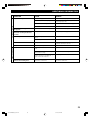
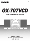
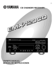
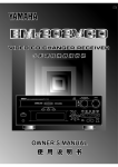
U
CRX-E500
RX-E400
CDC-E500
Receiver/CD Player
YAMAHA
YAMAHA
YAMAHA
YAMAHA
YAMAHA
YAMAHA
YAMAHA
ELECTRONICS CORPORATION, USA 6660 ORANGETHORPE AVE., BUENA PARK, CALIF. 90620, U.S.A.
CANADA MUSIC LTD. 135 MILNER AVE., SCARBOROUGH, ONTARIO M1S 3R1, CANADA
ELECTRONIK EUROPA G.m.b.H. SIEMENSSTR. 22-34, 25462 RELLINGEN BEI HAMBURG, F.R. OF GERMANY
ELECTRONIQUE FRANCE S.A. RUE AMBROISE CROIZAT BP70 CROISSY-BEAUBOURG 77312 MARNE-LA-VALLEE CEDEX02, FRANCE
ELECTRONICS (UK) LTD. YAMAHA HOUSE, 200 RICKMANSWORTH ROAD WATFORD, HERTS WD1 7JS, ENGLAND
SCANDINAVIA A.B. J A WETTERGRENS GATA 1, BOX 30053, 400 43 VÄSTRA FRÖLUNDA, SWEDEN
MUSIC AUSTRALIA PTY, LTD. 17-33 MARKET ST., SOUTH MELBOURNE, 3205 VIC., AUSTRALIA
Printed in Malaysia
0101CRXE500(U).H1-H4.E
1
OWNER’S MANUAL
V963100
02.7.9, 4:38 PM
SAFETY INSTRUCTIONS
10
CAUTION
RISK OF ELECTRIC SHOCK
DO NOT OPEN
CAUTION: TO REDUCE THE RISK OF
ELECTRIC SHOCK, DO NOT REMOVE
COVER (OR BACK). NO USER-SERVICEABLE
PARTS INSIDE. REFER SERVICING TO
QUALIFIED SERVICE PERSONNEL.
•
11
Explanation of Graphical Symbols
The lightning flash with arrowhead symbol,
within an equilateral triangle, is intended to alert
you to the presence of uninsulated “dangerous
voltage” within the product’s enclosure that may
be of sufficient magnitude to constitute a risk of
electric shock to persons.
The exclamation point within an equilateral
triangle is intended to alert you to the presence of
important operating and maintenance (servicing)
instructions in the literature accompanying the
appliance.
12
13
WARNING
TO REDUCE THE RISK OF FIRE OR ELECTRIC SHOCK,
DO NOT EXPOSE THIS UNIT TO RAIN OR MOISTURE.
14
1
2
3
4
5
6
7
8
9
Read Instructions – All the safety and operating instructions
should be read before the product is operated.
Retain Instructions – The safety and operating instructions
should be retained for future reference.
Heed Warnings – All warnings on the product and in the
operating instructions should be adhered to.
Follow Instructions – All operating and use instructions
should be followed.
Cleaning – Unplug this product from the wall outlet before
cleaning. Do not use liquid cleaners or aerosol cleaners. Use
a damp cloth for cleaning.
Attachments – Do not use attachments not recommended by
the product manufacturer as they may cause hazards.
Water and Moisture – Do not use this product near water –
for example, near a bath tub, wash bowl, kitchen sink, or
laundry tub; in a wet basement; or near a swimming pool;
and the like.
Accessories – Do not place this product on an unstable cart,
stand, tripod, bracket, or table. The product may fall,
causing serious injury to a child or adult, and serious
damage to the product. Use only with a cart, stand, tripod,
bracket, or table recommended by the manufacturer, or sold
with the product. Any mounting of the product should
follow the manufacturer’s instructions, and should use a
mounting accessory recommended by the manufacturer.
A product and cart combination should be
moved with care. Quick stops, excessive
force, and uneven surfaces may cause the
product and cart combination to overturn.
15
16
17
18
19
Ventilation – Slots and openings in the cabinet are provided
for ventilation and to ensure reliable operation of the
product and to protect it from overheating, and these
openings must not be blocked or covered. The openings
should never be blocked by placing the product on a bed,
sofa, rug, or other similar surface. This product should not
be placed in a built-in installation such as a bookcase or rack
unless proper ventilation is provided or the manufacturer’s
instructions have been adhered to.
Power Sources – This product should be operated only from
the type of power source indicated on the marking label. If
you are not sure of the type of power supply to your home,
consult your product dealer or local power company. For
products intended to operate from battery power, or other
sources, refer to the operating instructions.
Grounding or Polarization – This product may be equipped
with a polarized alternating current line plug (a plug having
one blade wider than the other). This plug will fit into the
power outlet only one way. This is a safety feature. If you
are unable to insert the plug fully into the outlet, try
reversing the plug. If the plug should still fail to fit, contact
your electrician to replace your obsolete outlet. Do not
defeat the safety purpose of the polarized plug.
Power-Cord Protection – Power-supply cords should be
routed so that they are not likely to be walked on or pinched
by items placed upon or against them, paying particular
attention to cords at plugs, convenience receptacles, and the
point where they exit from the product.
Lightning – For added protection for this product during a
lightning storm, or when it is left unattended and unused for
long periods of time, unplug it from the wall outlet and
disconnect the antenna or cable system. This will prevent
damage to the product due to lightning and power-line
surges.
Power Lines – An outside antenna system should not be
located in the vicinity of overhead power lines or other
electric light or power circuits, or where it can fall into such
power lines or circuits. When installing an outside antenna
system, extreme care should be taken to keep from touching
such power lines or circuits as contact with them might be
fatal.
Overloading – Do not overload wall outlets, extension
cords, or integral convenience receptacles as this can result
in a risk of fire or electric shock.
Object and Liquid Entry – Never push objects of any kind
into this product through openings as they may touch
dangerous voltage points or short-out parts that could result
in a fire or electric shock. Never spill liquid of any kind on
the product.
Servicing – Do not attempt to service this product yourself
as opening or removing covers may expose you to
dangerous voltage or other hazards. Refer all servicing to
qualified service personnel.
Damage Requiring Service – Unplug this product from the
wall outlet and refer servicing to qualified service personnel
under the following conditions:
a) When the power-supply cord or plug is damaged,
b) If liquid has been spilled, or objects have fallen into
the product,
c) If the product has been exposed to rain or water,
I CAUTION
0102CRXE500(U).Cau.E
2
02.7.9, 4:40 PM
SAFETY INSTRUCTIONS
d)
20
21
22
23
If the product does not operate normally by following
the operating instructions. Adjust only those controls
that are covered by the operating instructions as an
improper adjustment of other controls may result in
damage and will often require extensive work by a
qualified technician to restore the product to its normal
operation,
e) If the product has been dropped or damaged in any
way, and
f) When the product exhibits a distinct change in
performance - this indicates a need for service.
Replacement Parts – When replacement parts are required,
be sure the service technician has used replacement parts
specified by the manufacturer or have the same
characteristics as the original part. Unauthorized
substitutions may result in fire, electric shock, or other
hazards.
Safety Check – Upon completion of any service or repairs
to this product, ask the service technician to perform safety
checks to determine that the product is in proper operating
condition.
Wall or Ceiling Mounting – The unit should be mounted to
a wall or ceiling only as recommended by the manufacturer.
Heat – The product should be situated away from heat
sources such as radiators, heat registers, stoves, or other
products (including amplifiers) that produce heat.
Note to CATV system installer:
This reminder is provided to call the CATV system installer’s
attention to Article 820-40 of the NEC that provides
guidelines for proper grounding and, in particular, specifies
that the cable ground shall be connected to the grounding
system of the building, as close to the point of cable entry as
practical.
24
Outdoor Antenna Grounding – If an outside antenna or
cable system is connected to the product, be sure the
antenna or cable system is grounded so as to provide some
protection against voltage surges and built-up static charges.
Article 810 of the National Electrical Code, ANSI/NFPA 70,
provides information with regard to proper grounding of the
mast and supporting structure, grounding of the lead-in wire
to an antenna discharge unit, size of grounding conductors,
location of antenna discharge unit, connection to grounding
electrodes, and requirements for the grounding electrode.
EXAMPLE OF ANTENNA GROUNDING
MAST
ANTENNA
LEAD IN
WIRE
GROUND
CLAMP
ANTENNA
DISCHARGE UNIT
(NEC SECTION 810–20)
ELECTRIC
SERVICE
EQUIPMENT
GROUNDING CONDUCTORS
(NEC SECTION 810–21)
GROUND CLAMPS
POWER SERVICE GROUNDING
ELECTRODE SYSTEM
(NEC ART 250. PART H)
NEC – NATIONAL ELECTRICAL CODE
FCC INFORMATION (for US customers)
1.
2.
3.
IMPORTANT NOTICE : DO NOT MODIFY THIS
UNIT!
This product, when installed as indicated in the
instructions contained in this manual, meets FCC
requirements. Modifications not expressly approved
by Yamaha may void your authority, granted by the
FCC, to use the product.
IMPORTANT : When connecting this product to
accessories and/or another product use only high
quality shielded cables. Cable/s supplied with this
product MUST be used. Follow all installation
instructions. Failure to follow instructions could void
your FCC authorization to use this product in the USA.
NOTE : This product has been tested and found to
comply with the requirements listed in FCC
Regulations, Part 15 for Class “B” digital devices.
Compliance with these requirements provides a
reasonable level of assurance that your use of this
product in a residential environment will not result in
harmful interference with other electronic devices.
This equipment generates/uses radio frequencies and,
if not installed and used according to the instructions
found in the users manual, may cause interference
harmful to the operation of other electronic devices.
Compliance with FCC regulations does not guarantee
that interference will not occur in all installations. If
this product is found to be the source of interference,
which can be determined by turning the unit “OFF” and
“ON”, please try to eliminate the problem by using one
of the following measures:
Relocate either this product or the device that is being
affected by the interference.
Utilize power outlets that are on different branch (circuit
breaker or fuse) circuits or install AC line filter/s.
In the case of radio or TV interference, relocate/reorient
the antenna. If the antenna lead-in is 300 ohm ribbon
lead, change the lead-in to coaxial type cable.
If these corrective measures do not produce satisfactory
results, please contact the local retailer authorized to
distribute this type of product. If you can not locate the
appropriate retailer, please contact Yamaha Electronics
Corp., U.S.A. 6660 Orangethorpe Ave, Buena Park, CA
90620.
The above statements apply ONLY to those products
distributed by Yamaha Corporation of America or its
subsidiaries.
CAUTION II
0102CRXE500(U).Cau.E
3
02.7.9, 4:40 PM
CAUTION: READ THIS BEFORE OPERATING THIS UNIT
1
2
3
4
5
To assure the finest performance, please read this
manual carefully. Keep it in a safe place for future
reference.
Install this unit in a well ventilated, cool, dry, clean
place away from direct sunlight, heat sources, vibration,
dust, moisture or cold. In a cabinet, allow about 10 cm
(4 in.) of free space all around RX-E400 for adequate
ventilation.
Locate this unit away from other electrical appliances,
motors, or transformers to avoid humming sounds.
Do not expose this unit to sudden temperature changes
from cold to hot, nor locate this unit in an environment
with high humidity (i.e., a room with a humidifier) to
prevent condensation inside this unit, which may cause
an electrical shock, fire, damage to this unit, and/or
personal injury.
Avoid installing this unit in a location where foreign
objects may fall onto this unit or where this unit may be
exposed to liquid dripping or splashing. On the top of
this unit, do not place:
• Other components, as they may cause damage and/or
discoloration on the surface of this unit.
• Burning objects (i.e., candles), as they may cause fire,
damage to this unit, and/or personal injury.
• Containers with liquid in them, as they may fall, spilling
the liquid and causing an electrical shock to the user
and/or damage to this unit.
6
7
8
9
10
11
12
13
14
15
Do not cover this unit with a newspaper, tablecloth,
curtain, etc. in order not to obstruct heat radiation. If the
temperature inside this unit rises, it may cause fire,
damage to this unit, and/or personal injury.
Do not plug in this unit to a wall outlet until all
connections are complete.
Do not operate this unit upside-down. It may overheat,
possibly causing damage.
Do not use excessive force on switches, knobs and/or cords.
When disconnecting the power cord from the wall
outlet, grasp the plug; do not pull the cord.
Do not clean this unit with chemical solvents; this might
damage the finish. Use a clean, dry cloth.
Use only the voltage specified on this unit. Using this
unit with a higher voltage than specified is dangerous
and may cause fire, damage to this unit, and/or personal
injury. YAMAHA will not be held responsible for any
damage resulting from use of this unit with a voltage
other than as specified.
To prevent damage by lightning, disconnect the power
cord from the wall outlet during an electrical storm.
Do not attempt to modify or fix this unit. Contact
qualified YAMAHA service personnel when any service
is needed. The cabinet should never be opened for any
reason.
When not planning to use this unit for long periods of
time (i.e., vacation), disconnect the AC power plug from
the wall outlet.
16
17
18
Be sure to read the “Troubleshooting” section on
common operating errors before concluding that this
unit is faulty.
Before moving this unit, press STANDBY/ON to set the
unit in standby mode, then disconnect the AC power
plug from the wall outlet.
VOLTAGE SELECTOR (General model only)
The VOLTAGE SELECTOR on the rear panel of this
unit must be set for your local main voltage BEFORE
plugging into the AC main supply. Voltages are 110/120/
220/240 V AC, 50/60 Hz.
To reduce the risk of fire or electric shock, do not
expose this appliance to rain or moisture.
The unit is not disconnected from the AC power
source as long as it is connected to the wall outlet,
even if this unit itself is turned off. This state is
called the standby mode. In this state, this unit is
designed to consume a very small quantity of
power.
CAUTION FOR CARRYING THE UNIT
Before carrying the unit, first remove the disc from
the unit, press STANDBY/ON to turn the unit off,
then disconnect the AC power plug from the wall
outlet.
FOR CANADIAN CUSTOMERS
To prevent electric shock, match wide blade of plug
to wide slot and fully insert.
This Class B digital apparatus complies with
Canadian ICES-003.
CAUTION
Use of controls or adjustments or performance of
procedures other than those specified herein may
result in hazardous radiation exposure.
Laser component in this product is capable of
emitting radiation exceeding the limit for Class 1.
RX-E400 (U.S.A., Canada and General models)
The nameplate is located on the bottom of the unit.
IMPORTANT
Please record the serial number of this unit in the space
below.
MODEL:
Serial No.:
The serial number is located on the buttom of the unit.
Retain this Owner’s Manual in a safe place for future
reference.
We Want You Listening For A Lifetime
YAMAHA and the Electronic Industries Association’s Consumer
Electronics Group want you to get the most out of your equipment
by playing it at a safe level. One that lets the sound come through
loud and clear without annoying blaring or distortion – and, most
importantly, without affecting your sensitive hearing.
Since hearing damage from loud sounds is often
undetectable until it is too late, YAMAHA and the
Electronic Industries Association’s Consumer
Electronics Group recommend you to avoid
prolonged exposure from excessive volume levels.
III CAUTION
0102CRXE500(U).Cau.E
4
02.7.9, 4:40 PM
FEATURES
<RX-E400>
<CDC-E500>
• Minimum RMS output power per
channel 40 W + 40 W
(6Ω, 20 Hz to 20 kHz, 0.1% THD)
• Full operation system remote control
• 40-Station FM/AM preset tuning
• SUBWOOFER output terminal
• 3-Disc CD changer
• PLAYXCHANGE
Disc changing while playing
• S-bit DAC and 8fs digital filter
• Optical digital output
• Random, repeat, and program play
• CD TEXT display
• CD-RW compatible
The receiver (RX-E400) and CD player (CDC-E500) are the main units of the YAMAHA Piano Craft Series.
You can upgrade the system by adding the cassette deck (KX-E300) and MD recorder (MDX-E300)*.
* MD recorder (MDX-E300) may not be available for some areas.
CONTENTS
SUPPLIED ACCESSORIES ....................... 2
<CDC-E500>
CD PREVENTIVE CARE .......................... 2
NAMES OF BUTTONS AND CONTROLS
Front panel ......................................................... 15
Display............................................................... 15
Remote control .................................................. 16
GETTING STARTED
Notes on the transportation pad ........................... 3
Remote control .................................................... 4
Connecting the speakers and antennas ................ 5
Connecting the system ......................................... 6
Setting the clock .................................................. 7
Adjusting the brightness of the display ............... 7
<RX-E400>
NAMES OF BUTTONS AND CONTROLS
Front panel ........................................................... 8
Display ................................................................. 8
Remote control .................................................... 9
BASIC OPERATIONS
Listening to a source.......................................... 10
TUNING
Listening to the radio ......................................... 11
Presetting stations .............................................. 12
CD OPERATIONS
Playing a disc ..................................................... 17
Selecting the time display and CD TEXT ......... 18
Random-sequence play...................................... 19
Repeat play ........................................................ 19
Program play ..................................................... 20
SYSTEM CONTROL
Controlling other components ........................... 21
Before recording ................................................ 22
CD synchronized recording ............................... 22
Dubbing setting ................................................. 22
ADDITIONAL INFORMATION
Troubleshooting ................................................. 24
Specifications .................................................... 26
USING THE BUILT-IN TIMER
Before using the timer ....................................... 13
Timer play and recording .................................. 13
Sleep timer ......................................................... 14
1
0103CRXE500(U).01-02.E
1
02.7.9, 4:40 PM
SUPPLIED ACCESSORIES
After unpacking, check that the following parts are contained.
<RX-E400>
• Remote control
• AM loop antenna
POWER
1
2
3
1
4
2
5
3
6
4
7
5
8
6
9
7
0
8
+10
+100
REP
RANDOM
PROG
A
MODE
B
TEXT/TIME
C
DISC SKIP
D
E
• Indoor FM antenna
TAPE
DIRECTION
PRESET
MD
TUNER
PRESET
CD
TAPE
AUX
MD
REC/PAUSE
MODE
TAPE
REC/PAUSE
DUBBING
SLEEP
START
<CDC-E500>
DISPLAY
VOLUME
• Audio pin cable
• Batteries (AA, R6, UM-3)
• System control cable
CD PREVENTIVE CARE
• This compact disc player is designed for use with
following types of disc only. Never attempt to load any
other type of disc into the unit. The unit will also play
8-cm (3-inch) compact discs.
(Playback only)
• Be sure to use only CD-R and CD-RW discs made by
reliable manufacturers.
• Do not use a CD with tape, seals, or paste on it, because
damage to the unit may result.
• Do not use any disc that has had its surface printed by a
commercially-available label printer.
• Compact discs are not affected by small particles of
dust or fingerprints on their playing surface, but even so
they should be kept clean. Wipe by using a clean, dry
cloth. Do not wipe with a circular motion; wipe straight
outward from the center.
• Some discs cannot be played depending on the disc
characteristics or recording conditions (copyrightprotected in a particular way, etc.).
• Compact discs are not subjected to wear during play,
but damage to the disc surface when the disc is being
handled can adversely affect the disc’s play.
• Do not use cleaning discs or warped discs. All of these
could damage the unit.
To prevent a malfunction of this unit
• Do not use any non standard shaped CD (heart, etc.)
available on the market, because it may damage the
unit.
• Do not try to clean the disc’s surface by using any type
of disc cleaner, record spray, antistatic spray or liquid,
or any other chemical-based liquid, because such
substances might irreparably damage the disc’s surface.
• Do not expose discs to direct sunlight, high temperature
or high humidity for a long period of time, because
these might warp or otherwise damage the disc.
No!
2
0103CRXE500(U).01-02.E
2
02.7.9, 4:40 PM
GETTING STARTED
Notes on the
transportation pad
CDC-E500 is shipped with a transportation pad to prevent
impact to the internal mechanism that could occur during
transportation. Before turning CDC-E500 on, make sure
to remove the pad.
Before using the unit
1
Take off the caution label.
RA
NATU
2
L SO
UND
ACT
COMP
DISC
PLAY
ER
CDC–E
Installing the transportation pad
Keep the pad and the caution label, and reattach it as
described below whenever the unit is moved. Before
attaching it, remove all discs from the disc tray.
1
2
Press DISC 1 , DISC 2 or DISC 3 to open
the tray.
• When just one disc holder comes out, press DISC
SKIP so that two holders come out.
Pass the strip of the pad through the hole to bind two
disc holders together.
500
Draw the pad out.
NATURAL
SOUND
COMPAC
T DISC PLAYER
CDC–E50
0
3
Fix the strip on the pad with the caution label.
NATURAL SOUND COMPACT DISC PLAYER
4
CDC–E500
Press STANDBY/ON on CDC-E500 to close the
disc tray.
3
0104CRXE500(U).03-09.E
3
02.7.9, 4:40 PM
GETTING STARTED
Remote control
Remote control operation range
VOLUME
NATURAL SOUND
This remote control controls a whole system: not only
RX-E400 but also CDC-E500. Moreover, a cassette deck
(KX-E300) and MD recorder (MDX-E300) that level up
your system can be operated by it. Operating buttons for
each unit are explained on the pages below:
Receiver, RX-E400:
CD player, CDC-E500:
Cassette deck, KX-E300:
MD recorder, MDX-E300:
STEREO RECEIVER
RX–E400
STANDBY/ON
TIMER
DISPLAY
MEMORY
AUTO/MAN'L
TIMER ADJ
TIMER
BASS
PRESET/TUNING
PRESET/BAND
HOUR
TREBLE
MIN
MIN
MAX
INPUT
BALANCE
PHONES
–
p.8
p.15
p.21
p.21
+
–
+
R
L
Remote control
sensor
Battery installation
Within approximately
6 m (20 feet)
1
30°
3
30°
2
The remote control is shipped with a protection sheet to
prevent the surface from being scratched during
transportation.
When removing the sheet, first put adhesive tape on an
edge of the remote control so that the tape sticks to the
sheet. Then peel the sheet off with the tape.
ER
W
3
PO
3
3
3
6
6
6
2
2
9
6
Notes
1
8
7
7
7
7
4
4
8
8
4
4
1
8
5
5
1
1
5
5
• Use only AA, R6, UM-3 batteries for replacement.
• Be sure the polarities are correct. (See the illustration inside
the battery compartment.)
• Remove the batteries if the remote control will not be used for
an extended period of time.
• If batteries leak, dispose of them immediately. Avoid touching
the leaked material or letting it come in contact with clothing,
etc. Clean the battery compartment thoroughly before
installing new batteries.
Removing the protection sheet
2
If you find that the remote control must be used closer to
the main unit than usual, the batteries are weak. Replace
batteries with new ones.
9
Battery replacement
ER
Replace the battery compartment cover.
W
Insert batteries into the battery compartment.
Notes
• There should be no large obstacles between the remote control
and the main unit.
• If the remote control sensor is directly illuminated by strong
lighting (especially an inverter type of fluorescent lamp, etc.),
it might cause the remote control not to work correctly. In this
case, reposition the main unit to avoid direct lighting.
PO
Remove the battery compartment cover.
2
1
2
3
Note
• Do not scratch the remote control surface when peeling the
sheet off.
4
0104CRXE500(U).03-09.E
4
02.7.9, 4:40 PM
GETTING STARTED
Connecting the speakers and antennas
Never plug the AC power cord to the wall outlet until all connections are
completed.
Follow the steps as shown below to connect the system using the supplied cords and accessories. Be sure all connections are
made correctly, that is to say L (left) to L, R (right) to R, “+” to “+” and “–” to “–”.
3
Right speaker
Left speaker
FM antenna
2 AM antenna
C
IN
MD
OUT
FM ANT
75Ω UNBAL.
D
A
R
IN
L
GND
TAPE
OUT
AM
ANT
B
+
–
IN
CD
E
SUBWOOFER
OUT
SYSTEM
CONNECTOR
IN
6Ω MIN./SPEAKER
AUX
R
L
SPEAKERS
1
1
Connect the Speakers.
1 Unscrew the knob.
2 Remove approx. 10 mm (4”) of insulation from
each of the speaker wires and insert the bare wire
into the terminal.
3 Tighten the knob to secure the wire.
Red: positive(+)
Black: negative(–)
2
1
3
2
Connect the AM loop antenna.
Set up the AM loop antenna, then connect it.
4
3
To wall outlet
Connect the indoor FM antenna.
FM ANT
75 Ω UNBAL
4
Connect the AC power cord to a wall outlet.
Notes
• Use external FM/AM antennas if you need better reception.
Consult your dealer.
• The AM loop antenna should be placed apart from the main
unit. The antenna may be hung on a wall.
To connect the subwoofer (optional)
You can reinforce the bass frequencies by adding a
subwoofer (optional).
Connect the SUBWOOFER OUT terminal of the unit to
the INPUT terminal of the subwoofer.
GND
AM
ANT
5
0104CRXE500(U).03-09.E
5
02.7.9, 4:40 PM
GETTING STARTED
Connecting the system
Connecting RX-E400 and CDC-E500
1
2
3
Connect ‰ to ‰ using the Audio pin cable.
Insert the plugs into the jacks of the same color.
Connect RX-E400 and CDC-E500 with the system control cable.
The other SYSTEM CONNECTOR of CDC-E500 is for connecting MDX-E300 or KX-E300.
Connect the AC power plug of CDC-E500 to AC OUTLET of RX-E400.
This connection reduces the standby power consumption of CDC-E500.
C
To wall outlet
IN
MD
OUT
FM ANT
75Ω UNBAL.
D
A
R
IN
L
GND
TAPE
OUT
AM
ANT
B
+
–
IN
CD
E
<RX-E400>
SUBWOOFER
OUT
SYSTEM
CONNECTOR
IN
6Ω MIN./SPEAKER
AUX
R
1
SPEAKERS
L
System control cable
Audio pin cable
2
To RX-E400
3
ANALOG
E
L
OUT
DIGITAL
OPTICAL
SYSTEM
CONNECTOR
<CDC-E500>
OUT
R
Adding KX-E300 and MDX-E300 to the above system
(For details, refer to the owner's manual supplied with the respective component.)
1
2
3
4
Connect Å and ı of RX-E400 to Å and ı of KX-E300.
Connect Ç and Î of RX-E400 to Ç and Î of MDX-E300.
Connect an external component to the AUX terminal of RX-E400.
Connect DIGITAL OPTICAL OUT of CDC-E500 to DIGITAL OPTICAL IN of MDX-E300.
Take off the covers of the optical fiber cable plug, the DIGITAL OPTICAL OUT jack, and the DIGITAL OPTICAL
IN jack before making digital connections. Be sure to replace the terminal’s cover when the terminal on the rear panel
is not being used, in order to protect from dust.
Caution
• Never turn RX-E400 on until all connections between components have been completed.
• Never connect or disconnect the system control cable and/or power cord while the system components are turned on.
6
0104CRXE500(U).03-09.E
6
02.7.9, 4:40 PM
GETTING STARTED
Setting the clock
You must set the clock before you use the timer functions.
The clock is based on a 12-hour system for U.S. and
Canada models, and 24-hour system for Australia model.
STANDBY/ON
HOUR MIN
DISPLAY
VOLUME
NATURAL SOUND
STEREO RECEIVER
Adjusting the brightness
of the display
You can adjust the brightness of the display. If you have
connected the CD player (CDC-E500), cassette deck
(KX-E300), and/or MD recorder (MDX-E300) to this
unit, the brightness of the displays is automatically
adjusted to that of this unit.
RX–E400
DISPLAY
STANDBY/ON
TIMER
DISPLAY
MEMORY
AUTO/MAN'L
TIMER ADJ
TIMER
PRESET/BAND
PRESET/TUNING
MIN
MAX
VOLUME
BASS
HOUR
TREBLE
MIN
NATURAL SOUND
INPUT
STEREO RECEIVER
RX–E400
BALANCE
STANDBY/ON
PHONES
–
+
–
+
L
R
TIMER
DISPLAY
MEMORY
AUTO/MAN'L
TIMER ADJ
TIMER
BASS
PRESET/BAND
PRESET/TUNING
HOUR
TREBLE
MIN
MIN
MAX
INPUT
BALANCE
PHONES
TIME ADJ
1
2
3
4
PRESET/BAND
–
+
–
+
L
R
Turn on the power by pressing STANDBY/ON on
the front panel, or POWER on the remote control.
While the power is on, press DISPLAY to display
the time.
While holding TIME ADJ, press HOUR to set the
hour.
• If you want to move the time in the reverse
direction, press HOUR while holding TIME ADJ
and PRESET/BAND.
While holding TIME ADJ, press MIN to set the
minutes.
• If you want to move the time in the reverse
direction, press MIN while holding TIME ADJ
and PRESET/BAND.
INPUT
Press and hold DISPLAY for about two seconds so that
“Dimmer ±0” appears on the display. While holding
DISPLAY, turn INPUT clockwise to increase or
counterclockwise to decrease brightness.
Control Range: ±0 to –6 (Preset value: ±0)
To display the clock
Press DISPLAY.
The current time appears for about 8 seconds, then the
normal display returns. Some buttons and controls may
not work while the current time is displayed.
Note
• In the event of a power failure or when the AC power cord is
disconnected for more than five minutes, you must reset the
clock.
7
0104CRXE500(U).03-09.E
7
02.7.9, 4:40 PM
RX-E400 NAMES OF BUTTONS AND CONTROLS
Front panel
1 2
3 45 6 7 8
9
VOLUME
NATURAL SOUND
STEREO RECEIVER
RX–E400
STANDBY/ON
DISPLAY
TIMER
MEMORY
AUTO/MAN'L
TIMER ADJ
TIMER
PRESET/TUNING
PRESET/BAND
HOUR
BASS
TREBLE
MIN
MIN
MAX
INPUT
BALANCE
PHONES
–
0 q
+
w
1 STANDBY/ON (P.10)
2 TIMER indicator (P.13)
3 DISPLAY (P.13)
4 TIME ADJ (P.7) / MEMORY (P.12)
5 AUTO/MAN’L (P.11) / TIMER (P.13)
6 PRESET/BAND (P.11)
7 Display (This page)
8 PRESET/TUNING / (P.11)
HOUR/MIN (P.7/P.13)
–
+
R
L
e
r
t
9 VOLUME (P.10)
0 PHONES (P.10)
q Remote control sensor (P.4)
w BASS (P.10)
e TREBLE (P.10)
r BALANCE (P.10)
t INPUT (P.10)
Display
PRESET
EDIT
1
STEREO AUTO
TUNED MEMORY
23 456 7
1 Multi-information display
2 EDIT indicator
3 PRESET indicator (P.12)
4 STEREO indicator (P.11)
5 TUNED indicator (P.11)
TIMER
SLEEP
8
9
6 AUTO indicator (P.11)
7 MEMORY indicator (P.12)
8 TIMER indicator (P.13)
9 SLEEP indicator (P.14)
8
0104CRXE500(U).03-09.E
8
7/17/02, 3:46 PM
RX-E400 NAMES OF BUTTONS AND CONTROLS
Remote control
1 POWER (P.10)
2 Preset numbers (P.12)
3 A/B/C/D/E (P.12)
4 PRESET / (P.12)
5 TUNER (RX-E400) (P.12)
6 MD (MDX-E300) (P.21)
7 TAPE (KX-E300) (P.21)
8 CD (CDC-E500) (P.16)
9 AUX (The equipment connected to the AUX
terminal) (P.6)
0 SLEEP (P.14)
q DISPLAY (P.13)
w VOLUME %/fi (P.10)
POWER
1
2
3
1
2
3
1
4
2
5
3
6
4
7
5
8
6
9
7
0
8
+10
+100
REP
RANDOM
PROG
A
MODE
B
C
TEXT/TIME DISC SKIP
D
E
Note
TAPE
DIRECTION
PRESET
4
6
MD
TUNER
PRESET
CD
TAPE
AUX
MD
REC/PAUSE
MODE
0
TAPE
REC/PAUSE
DUBBING
SLEEP
5
• 5~9 are operation buttons and input selectors for each
component.
7
8
9
START
DISPLAY
q
w
VOLUME
9
0104CRXE500(U).03-09.E
9
02.7.9, 4:40 PM
BASIC OPERATIONS
Listening to a source
STANDBY/ON
TREBLE
1
2
VOLUME
STEREO RECEIVER
RX–E400
STANDBY/ON
TIMER
DISPLAY
MEMORY
AUTO/MAN'L
TIMER ADJ
TIMER
BASS
PRESET/TUNING
PRESET/BAND
HOUR
TREBLE
MIN
MIN
MAX
INPUT
BALANCE
PHONES
–
PHONES
+
–
+
L
BASS
3
R
BALANCE
4
POWER
1
2
3
1
4
2
5
3
6
4
7
5
8
6
9
7
0
8
+10
+100
REP
RANDOM
PROG
A
MODE
B
TEXT/TIME
C
DISC SKIP
D
MD
Adjust the volume level by turning VOLUME on the
front panel or pressing VOLUME %/fi on the remote
control.
If desired, adjust BASS, TREBLE, and BALANCE.
TREBLE: Turn this control clockwise to increase (or
counterclockwise to decrease) the high frequency
response.
BALANCE: Adjust the balance of the output volume
from the left and right speakers to compensate for
sound imbalance caused by the speaker location or
listening room conditions.
PRESET
CD
Play the source. (Refer to the owner’s manual
supplied with each selected component.)
BASS: Turn this control clockwise to increase (or
counterclockwise to decrease) the low frequency
response.
TAPE
DIRECTION
TUNER
5
6
E
PRESET
Select the desired input source by turning INPUT so
that the source appears on the display.
• When you operate the component connected to the
AUX terminal, turn INPUT to select AUX.
INPUT
POWER
Turn on the power by pressing STANDBY/ON on
the front panel, or POWER on the remote control.
• Piano Craft series components that have correct
system connections made to RX-E400 can be
controlled to turn to the on or standby mode by
RX-E400. However, once the connected
components are turned to the standby mode with
their respective STANDBY/ON, they cannot be
controlled by RX-E400 STANDBY/ON.
VOLUME
NATURAL SOUND
Set the volume to “MIN” by turning VOLUME.
TAPE
AUX
MD
REC/PAUSE
MODE
TAPE
REC/PAUSE
DUBBING
When you use headphones
START
SLEEP
DISPLAY
VOLUME %/fi
Connect the headphones to the PHONES jack. You can
listen to the sound to be output from the main speakers
through the headphones.
VOLUME
When you have finished using this
unit
Press STANDBY/ON on the front panel again or
POWER on the remote control to set this unit to the
standby mode.
Auto standby function
This unit will be put automatically into the standby mode
under the following conditions:
• A component connected with a system control cable is
selected as an input source.
• The component connected to this unit is in stop mode
and not operated for 30 minutes.
10
0105CRXE500(U).10-10.E
10
02.7.9, 4:40 PM
TUNING
Listening to the radio
You can find radio stations automatically and manually.
AUTO/MAN’L PRESET/TUNING
/
VOLUME
NATURAL SOUND
STEREO RECEIVER
DISPLAY
MEMORY
AUTO/MAN'L
TIMER ADJ
TIMER
BASS
PRESET/BAND
PRESET/TUNING
HOUR
TREBLE
MIN
MIN
MAX
INPUT
BALANCE
PHONES
–
+
–
+
L
1
2
3
RX–E400
STANDBY/ON
TIMER
Manual tuning
Follow steps 1 and 2 described in “Automatic
tuning.”
Press AUTO/MAN’L so that “AUTO” disappears
from the display.
Press PRESET/TUNING
(For a higher
(For a lower frequency) to select
frequency) or
your desired station.
• Each time you press PRESET/TUNING or
the frequency changes step by step.
,
R
PRESET/BAND
INPUT
Automatic tuning
1
2
3
4
5
Select TUNER by turning INPUT so that the
frequency of a radio station appears in the display.
Press PRESET/BAND to select the reception band.
Do not select the preset tuning mode (in which
“PRESET” appears on the display).
Press AUTO/MAN’L so that “AUTO” appears in the
display.
Press PRESET/TUNING
(For a higher
(For a lower frequency).
frequency) or
The unit starts searching for a station.
STEREO
AUTO
TUNED
When the unit finds a station, the unit stops searching
and “TUNED” appears on the display.
6
If the located station is not the one you want, repeat
steps 4 and 5 until a station you want is tuned.
Notes
• If automatic tuning search does not find the desired station, try
manual tuning as described next.
• When an FM stereo broadcast with sufficient signal strength is
received, “STEREO” appears on the display and you can listen
to stereo sound.
11
0106CRXE500(U).11-12.E
11
02.7.9, 4:40 PM
TUNING
To preset stations automatically
Presetting stations
The unit can preset station frequencies selected by
Automatic tuning or Manual tuning. Up to 40 stations can
be stored. With this function, you can select any desired
station by pressing the corresponding preset station
number.
PRESET/TUNING
/
STEREO RECEIVER
Select TUNER as input source by turning INPUT.
Press MEMORY for about 2 seconds.
• The unit starts presetting stations, “AUTO” and
“MEMORY” will flash on the display.
Received stations are stored to A1, A2...A8 sequentially.
After 40 stations or all FM and AM stations are stored, the
display will show the preset station A1.
To recall a preset station
VOLUME
NATURAL SOUND
1
2
RX–E400
STANDBY/ON
DISPLAY
TIMER
MEMORY
AUTO/MAN'L
TIMER ADJ
TIMER
BASS
PRESET/BAND
PRESET/TUNING
HOUR
TREBLE
MIN
MIN
MAX
INPUT
BALANCE
PHONES
–
+
–
+
L
Press TUNER and select the desired number by pressing
PRESET/BAND and PRESET/TUNING / on the
front panel or PRESET / , A/B/C/D/E and 1–8 on
the remote control.
R
POWER
MEMORY PRESET/BAND
INPUT
1–8
To preset stations manually
1
2
3
Tune in a desired station.
(Refer to the previous page for the tuning procedure.)
A/B/C/D/E
Press MEMORY.
1
2
3
1
4
2
5
3
6
4
7
5
8
6
9
7
0
8
+10
+100
REP
RANDOM
PROG
A
MODE
B
TEXT/TIME
C
DISC SKIP
D
Within about 5 seconds, use PRESET/TUNING
/ to select a desired preset number. Continue
pressing PRESET/TUNING / to select the
group of the preset stations (A, B, C, D, and E).
E
TAPE
DIRECTION
PRESET
TUNER
MD
PRESET
CD
TAPE
AUX
PRESET
STEREO
TUNED
MD
REC/PAUSE
MEMORY
MODE
4
Press MEMORY.
• “MEMORY”, “PRESET”, and preset number will
appear on the display.
TAPE
REC/PAUSE
DUBBING
SLEEP
DISPLAY
VOLUME
The arrow will appear for a second when
it is preset.
PRESET
STEREO
TUNED
5
MEMORY
Repeat steps 1 to 4 until all desired stations are
preset.
Notes
• A new setting can be preset in place of a previous one.
• The preset stations are retained for a week after you disconnect
the AC power cord or a power failure occurs.
12
0106CRXE500(U).11-12.E
12
START
02.7.9, 4:40 PM
TUNER
PRESET
/
USING THE BUILT-IN TIMER
3. Timer REC
Select the recording component by turning
INPUT. If you like to enjoy timer play with
TUNER or AUX, select “REC Mode OFF”.
Before using the timer
If you want to use the cassette deck, KX-E300 or the MD
Recorder, MDX-E300 for timer play or recording, you
must first make the connections as shown in “Connecting
the system” on page 6. For details, refer to the instructions
supplied with the MDX-E300 or KX-E300.
(Example)
Timer play and recording
4. ON Time
“ON Time” appears on the display for a second,
and changed to the time setting mode.
Press HOUR to set the hour.
Press MIN to set the minute.
By using the built-in timer, you can have the unit turn on
at a specified time and begin playing or recording
automatically. You can also specify the turn off time.
HOUR MIN
DISPLAY
VOLUME
NATURAL SOUND
STEREO RECEIVER
RX–E400
5. OFF Time
Set the time the same way as above.
If you set the ON time but not OFF time, the timer
play or recording will finish automatically after an
hour.
STANDBY/ON
TIMER
DISPLAY
MEMORY
AUTO/MAN'L
TIMER ADJ
TIMER
BASS
PRESET/BAND
PRESET/TUNING
HOUR
TREBLE
MIN
MIN
MAX
INPUT
BALANCE
PHONES
–
+
–
+
TIMER
1
L
Notes
R
• The display mode will change in about 8 seconds. If the
mode is changed before the setting is completed, call the
mode again by pressing DISPLAY once or more.
• If you select the input other than TUNER and AUX on
“2. Timer Input”, “3. Timer REC” is skipped.
INPUT
Press DISPLAY.
Whenever DISPLAY is pressed, the display mode
changes as follows:
1. Clock Time (TIMER on/off mode)
If you have not set the clock yet “Set Clock”
appears. You need to set the current time as
described on page 7.
2. Timer Input
Select the source to be played by turning INPUT.
• Timer recording is possible only when you
select TUNER or AUX.
2
Press TIMER to complete the timer setting.
The system is put in the standby mode.
• TIMER indicator lights up.
If you continue using the system, press STANDBY/
ON to turn on this unit.
To cancel the timer play setting
Press DISPLAY to show the current time, then press
TIMER so that “TIMER” goes off from the display. You
can also cancel by pressing TIMER in standby mode.
Note
• In the event of a power failure or when the AC power cord is
disconnected for more than five minutes, you must reset the
clock.
13
0107CRXE500(U).13-14.E
13
02.7.9, 4:40 PM
USING THE BUILT-IN TIMER
Sleep timer
The unit can be turned off automatically at a selected
SLEEP time.
PRESET
MD
TUNER
PRESET
CD
TAPE
AUX
MD
REC/PAUSE
MODE
SLEEP
TAPE
REC/PAUSE
DUBBING
START
SLEEP
DISPLAY
VOLUME
1
2
Play the desired sound source.
Press SLEEP repeatedly until the desired sleep time
appears in the display. Each time you press SLEEP,
the sleep time changes as follows:
SLEEP 2h00m
SLEEP 1h30m
SLEEP 1h00m
SLEEP 0h30m
SLEEP OFF
About 4 seconds after setting, the normal display will
resume.
• “SLEEP” will appear in the display.
3
The unit will turn off automatically when the selected
sleep time is reached.
14
0107CRXE500(U).13-14.E
14
02.7.9, 4:40 PM
CDC-E500 NAMES OF BUTTONS AND CONTROLS
Front panel
1
2 3
NATURAL SOUND
4
COMPACT DISC PLAYER
5
CDC-E500
DISC 1
DISC 2
DISC 3
DISC SKIP
STANDBY/ON
6 7 8
1 STANDBY/ON
2 Display (this page)
3 Disc tray (P.17)
4 DISC SKIP (P.18)
5 DISC 1/2/3 (Open/Close) (P.17)
6 & (Stop) (P.17)
7 ^ (Play/Pause) (P.17)
8 $/! (Skip/Search Backward)
⁄/› (Skip/Search Forward) (P.17)
Display
1
1
2
2 3 4
5
6
REP PROG RANDOM CD–TEXT
3 1DISC
3DISCS S F TITLE ARTIST TRACK
7
1 2 3 4 5 6 7 8 9 10
11 12 13 14 15 16 17 18 19 20
OOOOOOOOOOOO
9
8
1 Disc indicator
2 1 DISC/3 DISCS (Disc play mode) indicator
3 REP S/F (Single or Full) indicator (P.19)
4 PROG indicator (P.20)
5 RANDOM indicator (P.19)
6 CD-TEXT indicator (P.18)
0
7 Music calendar
8 Multi-information display
9 * (Pause) indicator
0 ‹ (Play) indicator
15
0108CRXE500(U).15-16.E
15
02.7.9, 4:40 PM
CDC-E500 NAMES OF BUTTONS AND CONTROLS
Remote control
POWER
1
1
2
3
1
4
2
5
3
6
4
7
5
8
6
9
7
0
8
+10
+100
REP
RANDOM
PROG
A
MODE
B
TEXT/TIME
C
DISC SKIP
2
3
5
6
9
0
D
4
7
E
8
q
TAPE
DIRECTION
PRESET
MD
TUNER
PRESET
CD
TAPE
w
AUX
MD
REC/PAUSE
MODE
1 Numeric buttons (P.17)
• +100 button is used when operating
MDX-E300.
2 REP (Repeat) (P.19)
3 RANDOM (Random) (P.19)
4 PROG (Program) (P.20)
5 MODE (P.19)
6 TEXT/TIME (P.18)
7 DISC SKIP (P.18)
8 ^ (Play/Pause) (P.17)
9 & (Stop) (P.17)
0 $ ! (Skip/Search Backward) (P.17)
q ⁄ › (Skip/Search Forward) (P.17)
w CD input (P.17)
TAPE
REC/PAUSE
DUBBING
SLEEP
START
DISPLAY
VOLUME
16
0108CRXE500(U).15-16.E
16
02.7.9, 4:40 PM
CD OPERATIONS
3
Playing a disc
Press DISC 1 , DISC 2 or DISC 3
the disc tray, and place a CD on the tray.
to open
DISC SKIP $/! ⁄/›
DISC
NATURAL SOUND
COMPACT DISC PLAYER
CDC-E500
RAL
NATU
ER
PLAY
E500
CDC–
PACT
D COM
SOUN
DISC 1
DISC 2
DISC 3
DISC SKIP
STANDBY/ON
4
& ^
5
Press the selected disc’s DISC button to close the
disc tray.
To insert other CDs, follow the same procedure.
Press ^ to start play.
This unit starts play.
POWER
To pause play
Numeric
buttons
1
2
3
1
4
2
5
3
6
4
7
5
8
6
9
7
0
8
+10
+100
REP
RANDOM
PROG
A
MODE
B
TEXT/TIME
C
DISC SKIP
Press ^.
To resume play, press ^ again.
To stop play
Press &.
To eject the CD
MODE
D
DISC SKIP
E
^
&
$ !/⁄ ›
Direct play
MD
TUNER
PRESET
CD
CD
TAPE
AUX
MD
REC/PAUSE
MODE
TAPE
REC/PAUSE
DUBBING
SLEEP
START
DISPLAY
VOLUME
2
To play a specific track on the disc
(Skip)
TAPE
DIRECTION
PRESET
1
Press to open the disc tray, and remove the CD from
the tray.
Select a desired track using the numeric button.
(Example: To select 35, press +10 three times so that
“3 –” appears in the display, then press 5.)
Skip play
Press ⁄/› to skip forward or $/! to skip
backward. Press once for each track to be skipped.
Notes
• You cannot enter a number that is higher than the last track
number on the selected disc.
• These operations can also be performed when the unit is in the
pause or stop mode.
• During stop mode, if ⁄/› or $/! is pressed, the
track number successively changes to higher numbers (or
lower numbers).
Turn on the power of RX-E400 and CDC-E500.
(Refer to page 10.)
To advance or reverse playback
rapidly (Search)
Press CD on the remote control in order to operate
the CD player by the remote control.
Press and hold ⁄/› to advance playback rapidly, and
$/! to reverse playback rapidly.
Note
• This unit cannot play a CD-R or CD-RW disc unless the disc is
finalized. Please make sure to finalize the disc on the CD
recorder before playing on this unit.
17
0109CRXE500(U).17-20.E
17
02.7.9, 4:40 PM
CD OPERATIONS
To change the disc play mode
Selecting the time
display and CD TEXT
If necessary, change the disc play mode by pressing
MODE on the remote control.
All disc play mode:
All disc on the disc tray are
played sequentially.
You can select any of four time displays by pressing
TEXT/TIME. When you play a CD with CD TEXT, the
disc title, artist name, and track name are also displayed.
POWER
3DISCS
Single disc play mode: Only the designated disc is
played.
1DISC
To select another disc
Press DISC SKIP once or more.
The circle around the selected disc number lights up.
(Example) When the disc 2 is selected.
1
2
3
1
4
2
5
3
6
4
7
5
8
6
9
7
0
8
+10
+100
REP
RANDOM
PROG
A
MODE
B
TEXT/TIME
C
DISC SKIP
D
TEXT/TIME
E
Each time you press TEXT/TIME the display changes as
follows:
The current track number
1 2 3
3 4 5 6 7
1 2 3 3DISCS
03
To exchange a disc (or discs) while
playing (PLAYXCHANGE)
3:53
3 4 5 6 7
1 2 3 3DISCS
03
You can open the disc tray without interrupting play by
pressing one of DISC 1/2/3 (not the currently playing
one).
-2:22
3 4 5 6 7
1 2 3 3DISCS
03(T)
50:33
3 4 5 6 7
1 2 3 3DISCS
03(T) -33:00
Elapsed time of the
current track
Remaining time of the
current track
Total disc play time
Total remaining time of
the disc
• “CD-TEXT” appears on the display if
a CD has CD TEXT.
Disc title
Artist name
Track name
Note
• The disc title, artist names, or track names may not be
displayed with some CD TEXT discs. In this case, “(NO
ENTRY)” appears on the display for about two seconds and
then go back to the time display.
18
0109CRXE500(U).17-20.E
18
02.7.9, 4:41 PM
CD OPERATIONS
Random-sequence play
The unit can play all the tracks in a random sequence.
Repeat play
You can play any desired track or disc repeatedly.
Press REP to select the repeat mode.
POWER
POWER
MODE
1
2
3
1
4
2
5
3
6
4
7
5
8
6
9
7
0
8
+10
+100
REP
RANDOM
PROG
A
MODE
B
TEXT/TIME
C
DISC SKIP
D
E
RANDOM
DISC SKIP
REP
1
2
3
1
4
2
5
3
6
4
7
5
8
6
9
7
0
8
+10
+100
REP
RANDOM
PROG
A
MODE
B
TEXT/TIME
C
DISC SKIP
D
1
2
If necessary, switch the disc play mode by pressing
MODE.
• If the single disc play mode is selected, select the
desired disc by pressing DISC SKIP.
Press RANDOM.
• “RANDOM” appears on the display.
The unit starts random sequence play.
To cancel random-sequence play
mode
Press & or RANDOM.
• “RANDOM” disappears from the display.
E
SINGLE REPEAT
The current track is played repeatedly.
REP
S
FULL REPEAT
When the CD player is in the single disc play mode:
The designated disc is played repeatedly.
When the CD player is in the all disc play mode:
All discs on the disc tray are played repeatedly.
REP
F
Notes
• This feature will not function during programming, or during
programmed play.
• If ⁄/› is pressed during random-sequence play, the next
randomly programmed track will be played.
If $/! is pressed, play will return to the beginning of the
current track.
• Total remaining time on the disc will not be displayed during
random-sequence play.
• In random-sequence play mode, all randomly
sequenced tracks are played repeatedly in the same
order.
To cancel repeat play mode
Press REP successively until “REP S” and “REP F”
disappear from the display.
19
0109CRXE500(U).17-20.E
19
7/17/02, 3:58 PM
CD OPERATIONS
Program play
4
• The selected track number and the total play time
of the programmed tracks appear on the display,
and it will soon be replaced by the display of the
next play order. Programmed track numbers on
the selected disc will stop flashing and light up on
the music calendar.
• Pressing TEXT/TIME displays the total play time
of the programmed tracks for about one second,
and then it is replaced by the display of the next
play order. When you program tracks of different
discs, total play time does not include the time
that takes to change discs.
By creating a program, you can enjoy listening to your
favourite tracks in any desired order. As many as 30
tracks can be programmed in sequence.
POWER
Numeric
buttons
TEXT/TIME
^
1
2
3
1
4
2
5
3
6
4
7
5
8
6
9
7
0
8
+10
+100
REP
RANDOM
PROG
A
MODE
B
TEXT/TIME
C
DISC SKIP
D
PROG
DISC SKIP
E
Use the numeric buttons to select a track number.
5
6
Repeat steps 3 and 4 to program more tracks. You
can select the same track again.
Press ^ to start program play.
&
$ !/⁄ ›
To stop program play mode
TAPE
DIRECTION
PRESET
TUNER
MD
Press &.
PRESET
CD
TAPE
AUX
MD
REC/PAUSE
Note
• ⁄/› or $/! can be used during program play to skip
to tracks within the program.
TAPE
REC/PAUSE
To check program data
MODE
DUBBING
SLEEP
START
DISPLAY
VOLUME
1.
Press & while the disc is playing to stop program
play.
2.
Press PROG. Then each time you press ⁄/› /
$/!, the track number and the program number
are displayed in the order of the program.
To change program data
1
2
Press & to stop the unit.
1.
Follow the preceding procedure described in “To
check program data.”
Press PROG.
• “PROG” and “P-01” light up on the display, and
all track numbers on the selected disc start
flashing.
2.
Display the track number to be changed by pressing
⁄/› / $/!.
3.
Press the numeric button of the desired track. The
previously programmed track will be cleared from
memory and the new one will be programmed.
1 2 3 3DISCS
PROG
1 2 3 4 5 6 7 8 9 10
11 12 13 14 15 16 17 18 19 20
P-01
3
If necessary, select the desired disc by pressing DISC
SKIP.
• Just after you change the disc, the CD player reads
the contents of the newly selected disc for a few
seconds. If you go on to the next step during this
internal operation, “WAIT” appears on the display
and your operation is canceled.
To delete all program data
When program play is stopped, press &.
Note
• Turning the unit to the standby mode or opening the disc tray
also deletes the program data.
20
0109CRXE500(U).17-20.E
20
7/17/02, 3:58 PM
SYSTEM CONTROL
Controlling other components
MDX-E300
POWER
1
2
3
4
1
2
3
1
4
2
5
3
6
4
7
5
8
6
9
7
0
8
+10
+100
REP
RANDOM
PROG
A
B
TEXT/TIME
C
DISC SKIP
MODE
D
E
6,1
8,3
9,4
7,2
TAPE
DIRECTION
PRESET
0
5
MD
KX-E300
TUNER
PRESET
CD
TAPE
5
AUX
q
1 Numeric buttons
2 REP (Repeat)
3 RANDOM
4 TEXT/TIME
5 PROG (Program)
6 ^ (Play/Pause)
7 ⁄ › (Skip/Search Forward)
8 $ ! (Skip/Search Backward)
9 & (Stop)
0 MD input
q MD REC/PAUSE
MD
REC/PAUSE
MODE
TAPE
REC/PAUSE
DUBBING
SLEEP
6
1 ^ (Play)
2 ⁄ › (Fast-forward)
3 $ ! (Rewind)
4 & (Stop)
5 TAPE input
6 TAPE REC/PAUSE
START
DISPLAY
VOLUME
21
0110CRXE500(U).21-23.E
21
02.7.9, 4:41 PM
SYSTEM CONTROL
Before recording
Dubbing setting
When you record by using MDX-E300 or KX-E300, you
must first make the connections as shown in “Connecting
the system” on page 6. For details, refer to the instructions
supplied with the MDX-E300 or KX-E300. A source from
the component which is connected to the AUX terminal
component can be recorded on a tape or MD.
There are six different combinations of components. Once
you choose a certain mode, recording starts and ends
automatically in a certain way for each mode.
AUX
MD
REC/PAUSE
DUBBING
MODE
CD synchronized
recording
MODE
TAPE
REC/PAUSE
DUBBING
SLEEP
START
DISPLAY
DUBBING
START
VOLUME
You can start and stop recording a CD on a MD or a tape
by pressing just one button.
D
E
^
&
MD
MD
REC/PAUSE
TUNER
PRESET
CD
CD
TAPE
AUX
MD
REC/PAUSE
MODE
TAPE
REC/PAUSE
DUBBING
SLEEP
START
TAPE
REC/PAUSE
DISPLAY
VOLUME
1
2
3
Decide the combination of the components. Each
time you press DUBBING MODE, the mode will
change in the below order.
1
TAPE
DIRECTION
PRESET
1
• Recording automatically starts from the beginning
of the tape. (By pressing DUBBING START, the
tape automatically rewinds to the beginning if it is
in the middle.)
• When the recording on side A finishes while a
track is being played back, the recording on side B
starts from the beginning of the same track.
• The sound is automatically faded out when it gets
close to the end of side B.
Press CD.
Press MD REC/PAUSE to record on a MD or
TAPE REC/PAUSE to record on a tape.
2
Press ^.
Recording starts automatically on MDX-E300 or
KX-E300.
To stop recording
Press &.
• Pressing & on CDC-E500 stops CD play and turn the
recording component into “REC standby” mode.
• Pressing & on MDX-E300 or KX-E300 stops recording,
while the CD player keeps on playing.
3
Play unit
Note
• Recording does not pause while CDC-E500 changes discs.
When recording the tracks of different discs, it is
recommended to set the CD player to single disc play mode
and record the discs individually. When recording the
programmed sequence of the tracks of different discs, make
sure that the length of the MD or the tape is longer than the
total play time of the programmed tracks, so that it is enough
to cover the time for changing discs.
• Same as CD = TAPE
22
0110CRXE500(U).21-23.E
22
02.7.9, 4:41 PM
Record unit
SYSTEM CONTROL
4
Play unit
Record unit
• Recording automatically starts at the beginning of
the tape. (By pressing DUBBING START, the
tape automatically rewinds to the beginning if it is
in the middle.)
2
Press DUBBING START to start recording.
Note
• The displays 1~4 which include the component you have
not connected to your receiver (RX-E400) will be skipped.
• Recording does not pause while CDC-E500 changes discs.
When recording the tracks of different discs, it is
recommended to set the CD player to single disc play mode
and record the discs individually. When recording the
programmed sequence of the tracks of different discs, make
sure that the length of the MD or the tape is longer than the
total play time of the programmed tracks, so that it is enough
to cover the time for changing discs.
To stop dubbing
Press &.
23
0110CRXE500(U).21-23.E
23
02.7.9, 4:41 PM
ADDITIONAL INFORMATION
Troubleshooting
If the unit fails to operate normally, check the following points to determine whether the fault can be corrected by the
simple measures suggested. If it cannot be corrected, or if the fault is not listed in the SYMPTOM column, disconnect the
power cord and contact your authorized YAMAHA dealer or service center for help. When taking the service, the
MDX-E300 or KX-E300 may be needed. For details, contact your authorized YAMAHA dealer or service center.
RX-E400 RECEIVER
SYMPTOM
CAUSE
REMEDY
The unit does not switch ON when
the STANDBY/ON is pressed.
The AC power cord is not connected or not
completely connected.
Securely connect the power cord.
No sound from one speaker.
Loose speaker connections.
Connect properly.
The sound suddenly goes off.
The protection circuit has been activated
because of a short circuit, etc.
Check the speaker wires are not touching each other
and then turn the unit back on.
No sound from an external unit
connected with this unit or play does
not begin.
Incorrect cord connections.
Connect the cords properly. If the problem persists,
the cords may be defective.
Input source selection is not proper.
Make a proper input source selection.
Sound distorted.
The component connected to this unit is
disconnected from AC outlet.
Connect the AC power cord of the component to an
AC outlet.
Excessive static in FM broadcasts.
Interference from starting motor of a nearby
car.
Position the FM antenna as high and as far away
from nearby roads as possible. Connect using a
coaxial cable.
Interference from the thermostat of a nearby
electrical appliance.
Noise increases during stereo
broadcasts.
Antenna input is too weak due to obstructions
or excessive distance from the broadcasting
station.
Check the antenna connection.
Stereo broadcasts are noisy and
STEREO indicator blinks on and off.
Insufficient antenna input.
Install an antenna appropriate for the electric field
strength of your area.
Cannot select preset stations.
Preset memory has been erased.
Reprogram memory presets.
Buzzing or static during AM
broadcasts.
Interference from sources such as lightning,
fluorescent lights, electric motors or thermostat
of nearby electrical appliance.
The problem is difficult to eliminate, but can be
lessened by grounding AM loop antenna.
TV or microprocessor is being used nearby.
Move away from TV or microprocessor.
Radio signal is weak or the antenna is not
properly connected.
Properly connect the AM loop antenna.
AM broadcast sensitivity is poor.
Install a multi-element type FM antenna if possible.
Change orientation of the AM loop antenna.
Install an external AM loop antenna.
Cannot set timer.
Current time is not set.
Set current time.
The unit does not work normally.
The internal microcomputer has been frozen
by an external electric shock (lightning,
excessive static electricity, etc.) or the power
supply with low voltage.
Unplug the AC power cord from the wall outlet, and
then plug in again after about one minute.
24
0111CRXE500(U).24-27.E
24
02.7.9, 4:41 PM
REMOTE CONTROL
CDC-E500 CD PLAYER
ADDITIONAL INFORMATION
SYMPTOM
CAUSE
REMEDY
Play does not begin.
The disc is damaged.
Check the disc carefully; replace it if necessary.
There is moisture on the laser pick-up.
Wait 20 to 30 minutes after switching the unit ON
before trying to play a disc.
The disc has been loaded upside down.
Reload the disc with the label side facing up.
The disc is dirty.
Clean the disc.
Play is delayed, or begins at the
wrong place.
The disc may be scratched or damaged.
Check the disc carefully; replace it if necessary.
CD synchronized recording or
Automatic recording function does
not work.
The system cable is not connected securely.
Connect the system cable properly.
Sound “skips.”
The unit is being subjected to vibrations or
impacts.
Relocate the unit.
The disc is dirty.
Clean the disc.
Sound “hums.”
Improper cable connections.
Securely connect the audio cables. If the problem
persists, the cables may be defective.
Noise from inside of the unit.
The disc may be warped.
Replace the disc.
The remote control does not work.
The batteries of the remote control are too
weak.
Replace the batteries with new ones.
Remote control is too far away or is being
used at an incorrect angle.
Use within 6 meters and 60 degree radius.
Direct sunlight or lighting (of an inverter type
of fluorescent lamp, etc.) is striking the
remote control sensor of the unit.
Change the position of the unit.
Remote control is being used near TV set
with a remote control sensor.
Relocate this unit away from the TV or cover the
TV’s remote control sensor.
TV functions strangely when the
remote control is being used.
25
0111CRXE500(U).24-27.E
25
02.7.9, 4:41 PM
ADDITIONAL INFORMATION
Specifications
<RX-E400>
<CDC-E500>
Amplifier section
CD player section
Minimum RMS output power per channel
................................................ 55 W + 55 W (6Ω 1kHz 0.1% THD)
.............................. 40 W + 40 W (6Ω 20 Hz to 20 kHz 0.1% THD)
DIN Standard output power per channel (Europe model)
................................................ 60 W + 60 W (4Ω 1kHz 0.7% THD)
Input sensitivity/Impedance
CD/TAPE/MD/AUX ................................................. 150 mV/47 kΩ
Frequency response
CD etc. ..................................................... 20 Hz to 20 kHz, ±0.5 dB
Total Harmonic Distortion (20 Hz to 20 kHz)
CD etc. 20 W, 6 Ω ................................................................... 0.04%
Signal-to-Noise ratio (IHF-A Network)
CD etc. (250 mV, Input shorted) ............................................. 98 dB
Output level/Impedance
PHONES ..................................................................... 0.43 V/330 Ω
D/A converter ...................................................................... S-bit DAC
Frequency response ...................................... 2 Hz to 20 kHz, ±0.5 dB
S/N ratio ................................................................................... 102 dB
Tuner section
Tuning range
FM
[U.S.A. and Canada models] ................................ 87.5 – 107.9 MHz
[U.K., Europe, Australia and General models]
.......................................................................... 87.50 – 108.00 MHz
AM
[U.S.A. and Canada models] ................................... 530 – 1710 kHz
[U.K., Europe and Australia models] ...................... 531 – 1611 kHz
[General model] ....................................... 530/531 – 1710/1611 kHz
Sensitivity
FM (S/N 30dB) ....................................................................... 1.0 µV
AM .................................................................................... 300 µV/m
Laser diode properties
•
•
•
•
Material: GaAIAs
Wavelength: 780 nm
Emission duration: continuous
Laser output: max. 44.6 µW*
* This output is the value measured at a distance of about 200 mm
from the objective lens surface on the Optical Pick-up Block.
General
Power supply
[U.S.A. and Canada models] ................................. AC 120 V, 60 Hz
[Australia model] ................................................... AC 240 V, 50 Hz
Power consumption ..................................................................... 13 W
Power consumption (standby mode) ......................................... 3.8 W
Dimensions (W x H x D) ..................................... 217 x 108 x 347 mm
Weight ........................................................................................ 3.5 kg
Specifications are subject to change without notice.
General
Power supply
[U.S.A. and Canada models] ................................. AC 120 V, 60 Hz
[Australia model] ................................................... AC 240 V, 50 Hz
[U.K. and Europe models] ..................................... AC 230 V, 50 Hz
[General model] .......................... AC 110/120/220/240 V, 50/60 Hz
Power consumption
[U.S.A. and Canada models] .................................................. 110 W
[U.K., Europe, Australia and General models] ...................... 125 W
Power consumption (standby mode)
[U.S.A. and Canada models] ................................................... 0.7 W
[U.K., Europe and Australia models] ...................................... 0.8 W
Dimensions (W x H x D) .................................. 217 x 108 x 372 mm
Weight ..................................................................................... 5.4 kg
26
0111CRXE500(U).24-27.E
26
02.7.9, 4:41 PM
U
CRX-E500
RX-E400
CDC-E500
Receiver/CD Player
YAMAHA
YAMAHA
YAMAHA
YAMAHA
YAMAHA
YAMAHA
YAMAHA
ELECTRONICS CORPORATION, USA 6660 ORANGETHORPE AVE., BUENA PARK, CALIF. 90620, U.S.A.
CANADA MUSIC LTD. 135 MILNER AVE., SCARBOROUGH, ONTARIO M1S 3R1, CANADA
ELECTRONIK EUROPA G.m.b.H. SIEMENSSTR. 22-34, 25462 RELLINGEN BEI HAMBURG, F.R. OF GERMANY
ELECTRONIQUE FRANCE S.A. RUE AMBROISE CROIZAT BP70 CROISSY-BEAUBOURG 77312 MARNE-LA-VALLEE CEDEX02, FRANCE
ELECTRONICS (UK) LTD. YAMAHA HOUSE, 200 RICKMANSWORTH ROAD WATFORD, HERTS WD1 7JS, ENGLAND
SCANDINAVIA A.B. J A WETTERGRENS GATA 1, BOX 30053, 400 43 VÄSTRA FRÖLUNDA, SWEDEN
MUSIC AUSTRALIA PTY, LTD. 17-33 MARKET ST., SOUTH MELBOURNE, 3205 VIC., AUSTRALIA
Printed in Malaysia
0101CRXE500(U).H1-H4.E
1
OWNER’S MANUAL
V963100
02.7.9, 4:38 PM