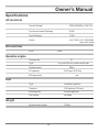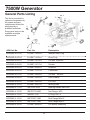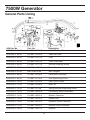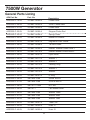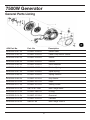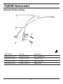
1
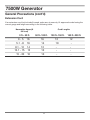
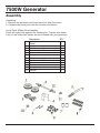
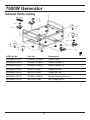
APG3303
TM
Owner’s Manual
7500W Generator
HAVE QUESTIONS OR NEED SERVICE
DO NOT RETURN TO STORE!
866.882.8088
www.allpoweramerica.com
7500W Generator
Topic
Page
Limited Warranty
3
Safety Guidelines
5
General Precautions
6
Battery
15
Assembly
16
Operation
19
Inspection, Cleaning and Maintenance
24
Installation
25
Compliance
27
Speci fications
28
General Parts Listing
29
WARNING! READ AND UNDERSTAND ALL SAFETY PRECAUTIONS
IN THIS MANUAL BEFORE OPERATING. FAILURE TO COMPLY WITH
INSTRUCTIONS IN THIS MANUAL COULD RESULT IN PERSONAL
INJURY, PROPERTY DAMAGE, AND/ OR VOIDING OF YOUR
WARRANTY. ALL POWER AMERICA WILL NOT BE LIABLE FOR ANY
DAMAGE BECAUSE OF FAILURE TO FOLLOW THESE INSTRUCTIONS.
2
Owner’s Manual
Limited Warranty
All-Power America warrants to the original purchaser who uses the product in a consumer
application (personal, residential or household usage) that all products covered under this
warranty are free from defects in material and workmanship for one year from the date of
purchase. All products covered by this limited warranty which are used in commercial applications
(i.e. income producing) are warranted to be free of defects in material and workmanship for
90 days from the date of original purchase. Products covered under this warranty include air
compressors, air tools, service parts, pressure washers and generators.
All-Power America will repair or replace, at All-Power America’s sole option, products or
components which have failed within the warranty period. Service will be schelduled according
to the normal work flow and business hours at the service center location, and the availibility of
replacement parts. All decisions of All-Power America with regard to this limited warranty shall be
final.
This warranty gives you specific legal rights, and you may also have other rights which vary from
state to state.
RESPONSIBILITY OF ORIGINAL PURCHASER (initial User):
To process a warranty claim on this product, DO NOT return item to the retailer. The product must
be evaluated by an Authorized Warranty Service Center. For the location of the nearest Authorized
Warranty Service Center contact the retailer or place of purchase.
Retain original cash register sales receipt as proof of purchase for warranty to work.
Use reasonable care in the operation and maintenance of the product as described in the Owner’s
Manual(s).
Deliver or ship the product to the Authorized Warranty Service Center. Freight costs, if any must
be paid by the purchaser.
If the purchaser does not receive satisfactory results form the Authorized Warranty Sercive
Center, the purchser should contact All-Power America.
3
7500W Generator
Limited Warranty (cont’d)
THIS WARRANTY DOES NOT COVER:
• Merchandise sold as reconditioned, used as rental equipment, or floor or display models.
• Merchandise that has become damaged or inoperative because of ordinary wear, misuse,
cold, heat, rain, excessive humidity, freeze damage, use of improper chemicals, negligence,
accident, failure to operate the product in accordance with the instructions provided in the
Owner’s Manual(s) supplied with the product, improper maintenance, the use of accessories or
attachments not recommended by All-Power America, or unauthorized repair or alterations.
• Repair and transportation costs of merchandise determine not to be defective.
• Costs assoiciated with assembly, required oil, adjustments or other installation and start-up
costs.
• Expendable parts or accessories supplied with the product which are expected to become
inoperative or unusable after a reasonable period of use.
• Merchandise sold by All-Power America which has been manufactured by and identi
?ed as the
product of another company, such as gasoline engines. The product manufacturer’s warranty, if
any, will apply.
• ANY INCIDENTAL, INDIRECT OR CONSEQUENTIAL LOSS, DAMAGE, OR EXPENSE THAT
MAY RESULT FROM ANY DEFECTS, FAILURE OR MALFUNCTION OF THE PRODUCT IS
NOT COVERED BY THIS WARRANTY. Some states do not allow the exclusion, so it may not
apply to you.
• IMPLIED WARRANTIES, INCLUDING THOSE OF MERCHANTABILITY OR FITNESS FOR
A PARTICULAR PURPOSE, ARE LIMITED TO ONE YEAR FROM THE DATE OF ORIGINAL
PURCHASE. Some states do not allow limitations on how long an implied warranty lasts, so the
above limitations may not apply to you.
4
Owner’s Manual
Safety Guidelines - Definitions
This manual contains important information that you need to know and
understand in order to protect YOUR SAFETY and to PREVENT
EQUIPMENT PROBLEMS. The following symbols help you recognize this
information. Please read the manual and pay attention to these sections.
Save These Important Safety Instructions!
Read and understand all of these safety instructions. Be
sure to retain them for future use.
WARNING! WARNINGS INDICATE A CERTAINTY OR STRONG
POSSIBILITY OF PERSONAL INJURY OR DEATH IF
INSTRUCTIONS ARE NOT FOLLOWED.
CAUTION: CAUTIONS INDICATE A POSSIBILITY OF
EQUIPMENT DAMAGE IF INSTRUCTIONS ARE NOT
FOLLOWED.
NOTE: NOTES GIVE HELPFUL INFORMATION
WARNING! IMPROPER OPERATION OR MAINTENANCE
OF THIS PRODUCT COULD RESULT IN SERIOUS INJURY
AND PROPERTY DAMAGE. READ AND UNDERSTAND ALL
WARNINGS AND OPERATING INSTRUCTIONS BEFORE USING
THIS EQUIPMENT. WHEN USING AIR TOOLS, BASIC SAFETY
PRECAUTIONS SHOULD ALWAYS BE FOLLOWED TO REDUCE
THE RISK OF PERSONAL INJURY.
5
7500W Generator
General Precautions
WARNING! FAILURE TO FOLLOW THESE INSTRUCTIONS CAN RESULT IN
SEVERE INJURY OR DEATH.
CAUTION: FAILURE TO FOLLOW THESE INSTRUCTIONS CAN ALSO
RESULT IN DAMAGE TO THE TOOL AND/OR THE ITEM YOU ARE WORKING
ON.
Carbon Monoxide
When this tool is running, ensure that the area is well ventilated. Never run the
engine in an enclosed area. Run the engine in an open area or with an exhaust
evacuation system in an enclosed area.
WARNING! THE EXHAUST CONTAINS POISONOUS CARBON MONOXIDE
GAS THAT CAN CAUSE LOSS OF CONSCIOUSNESS AND MAY LEAD TO
DEATH.
Gasoline and Oil
This product requires oil and fuel. Attempting to start the engine without oil will ruin
the engine and void the warranty. Work in well ventilated area. Keep cigarettes,
flames or sparks away from the work area or where gasoline is stored.
WARNING! GASOLINE IS EXTREMELY FLAMMABLE AND IS EXPLOSIVE
UNDER CERTAIN CONDITIONS. KEEP OUT OF REACH OF CHILDREN.
• Gasoline fuel and fumes are flammable and potentially explosive. Use proper fuel storage and
handling procedures. Always have multiple ABC class fire extinguishers nearby.
• Keep the generator and surrounding area clean at all times.
• Fuel or oil spills must be cleaned up immediately. Dispose of fluids and cleaning materials as per
any local, state, or federal codes and regulations. Store oily rags in a covered metal container.
• Never store fuel or other flammable materials near the generator.
6
Owner’s Manual
General Precautions (cont’d)
Gasoline and Oil (cont’d)
• Do not smoke, or allow sparks, flames or other sources of ignition around the engine and fuel
tank. Fuel vapors are explosive.
• Keep grounded conductive objects, such as tools, away from exposed, live electrical parts and
connections to avoid sparking or arcing. These events could ignite fumes or vapors.
• Do not refill the fuel tank while the engine is running or while the engine is still hot. Do not
operate the generator with known leaks in the fuel system
• Excessive buildup of unburned fuel gases in the exhaust system can create a potentially
explosive condition. This buildup can occur after repeated failed start attempts, valve testing, or
hot engine shutdown. If this occurs, open exhaust system drain plugs, if equipped, and allow the
gases to dissipate before attempting to restart the generator.
• Use only engine manufacturer recommended fuel and oil.
Hot Components
WARNING! ENGINE AND EXHAUST SYSTEM PARTS BECOME VERY
HOT AND REMAIN HOT FOR SOME TIME AFTER THE ENGINE IS RUN. WEAR
INSULATED GLOVES OR WAIT UNTIL THE ENGINE AND EXHAUST SYSTEM
HAVE COOLED BEFORE HANDLING THESE PARTS.
Power Output
This generator is not designed to power sensitive electronic equipment (including computers
and medical devices) without the addition of an approved line conditioner, which is sold separately.
CAUTION: ATTEMPTING TO POWER SENSITIVE ELECTRONIC EQUIPMENT
WITHOUT THE USE OF AN APPROVED LINE CONDITIONER MAY CAUSE
DAMAGE TO THE EQUIPMENT. ALL POWER AMERICA IS NOT RESPONSIBLE
FOR ANY DIRECT OR INDIRECT DAMAGE CAUSED BY FAILURE TO USE AN
APPROVED LINE CONDITIONER.
7
7500W Generator
General Precautions (cont’d)
Work Area
• Keep your work area clean and well lit. Cluttered benches and dark areas invite accidents.
• Do not operate power tools in explosive atmospheres, such as in the presence of flammable
liquids, gases, or dust. Generators create sparks which may ignite the dust or fumes.
• Keep bystanders, children, and visitors away while operating a generator. Provide barriers or
shields as needed.
Electrical Safety
• Grounded tools must be plugged into an outlet properly installed and
grounded in accordance with all codes and ordinances. Never remove the
grounding prong or modify the plug in any way. Do not use any adapter
plugs.
• Grounding provides a low-resistance path to carry electricity away from the
user in the event of an electrical malfunction.
• Double insulated tools are equipped with a polarized plug where one blade is wider than the
other. This plug fits in a polarized outlet only one way. If the plug does not fit fully in the outlet,
reverse the plug. If it still does not fit, contact a qualified electrician to install a polarized outlet.
Do not change the plug in any way. Double insulation eliminates the need for the three-wire
grounded power cord and grounded power supply system.
• Avoid body contact with grounded surfaces such as pipes, radiators, ranges, and refrigerators.
There is an increased risk of electric shock if your body is grounded.
• Do not expose generator to rain or wet conditions. Water entering a generator will increase the
risk of electric shock.
• Do not abuse the power cord. Keep power cords away from heat, oil, sharp edges, or moving
parts. Replace damaged power cords immediately. Damaged power cords increase the risk of
electric shock.
• When operating a power tool outside, use an outdoor extension cord marked “W-A” or “W”.
These extension cords are rated for outdoor use, and reduce the risk of electric shock.
8
Owner’s Manual
General Precautions (cont’d)
Electrical Safety (cont’d)
• All connections and conduits from the generator to the load must only be installed by trained and
licensed electricians, and in compliance with all relevant local, state, and federal electrical
codes and standards, and other regulations where applicable.
• The generator must be earth-grounded for fixed installations in accordance with all relevant
electrical codes and standards before operation.
• Do not attempt to connect or disconnect load connections while standing in water, or on wet or
soggy ground.
• Do not touch electrically energized parts of the generator and interconnecting cables or
conductors with any part of the body, or with any non-insulated conductive object.
• Connect the generator only to a load or electrical system (120 volt) that is compatible with the
electrical characteristics and rated capacities of the generator.
• Before servicing equipment powered by the generator, disconnect the equipment from its power
input.
• Keep all electrical equipment clean and dry. Replace any wiring where the insulation is cracked,
cut abraded or otherwise degraded. Replace terminals that are worn, discolored, or corroded.
Keep terminals clean and tight.
• Insulate all connections and disconnected wires.
• Guard against electric shock. Prevent body contact with grounded surfaces such as pipes,
radiators, ranges, and refrigerator enclosures.
Personal Safety
• Stay alert. Watch what you are doing, and use common sense when operating a generator. Do
not use generator while tired or under the influence of drugs, alcohol, or medication. A moment
of inattention while operating generators may result in serious personal injury.
• Dress properly. Do not wear loose clothing or jewelry. Contain long hair. Keep your hair, clothing,
and gloves away from moving parts. Loose clothes, jewelry, or long hair can be caught in
moving parts.
9
7500W Generator
General Precautions (cont’d)
Personal Safety (cont’d)
• Avoid accidental starting. Make sure the power switch is in its “OFF” position, and disconnect
the spark plug wire when not in use.
• Remove adjusting keys or wrenches before turning the generator on. A wrench or a key that is
left attached to a rotating part of the generator may result in personal injury.
• Do not overreach. Keep proper footing and balance at all times.
• Use safety equipment. Always wear eye protection. Wear ANSI approved safety impact eye
goggles. Dust mask, non-skid safety shoes, hard hat, or hearing protection must be used for
appropriate conditions.
• Do not force the generator. Use the correct generator for your application. The correct generator
will do the job better and safer at the rate for which it is designed.
• Do not use the generator if the power switch does not turn it on or off. Any generator that cannot
be controlled with the power switch is dangerous and must be replaced.
Generator Use and Care
Make sure the power switch is in its “OFF” position and disconnect the spark plug wire before
making any adjustment, changing accessories, or storing the generator. Such preventive safety
measures reduce the risk of starting the generator accidentally.
Store idle generators out of reach of children and other untrained persons. Generators are
dangerous in the hands of untrained users.
Maintain generators with care. Do not use damaged generator. Tag damaged generators “Do not
use” until repaired.
Check for misalignment or binding of moving parts, breakage of parts, and any other condition that
may affect the generator’s operation. If damaged, have the generator serviced before using. Many
accidents are caused by poorly maintained generators.
Use only accessories that are recommended by the manufacturer for your model. Accessories that
may be suitable for one generator may become hazardous when used on another generator.
10
Owner’s Manual
General Precautions (cont’d)
Servicing
Maintain labels and name plates on the generator and engine. These carry important information.
If unreadable or missing, contact All Power America immediately for a replacement.
Generator service must be performed only qualified repair personnel. Service or maintenance
performed by unqualified personnel could result in a risk of injury.
When servicing a generator, use only identical replacement parts. Follow all appropriate
instructions in this manual. Use of unauthorized parts or failure to follow maintenance instructions
may create a risk of electric shock or injury.
Heart Pacemakers
WARNING! PEOPLE WITH PACEMAKERS SHOULD CONSULT THEIR
PHYSICIAN(S) BEFORE USING THIS PRODUCT. ELECTROMAGNETIC
FIELDS IN CLOSE PROXIMITY TO A HEART PACEMAKER COULD CAUSE
INTERFERENCE TO OR FAILURE OF THE PACEMAKER.
Installation
• Ensure installation meets all applicable safety, and local and national electrical codes. Have
installation performed by a qualified, licensed electrician and building contractor.
• All electrical work, including the earth-ground connection, should be completed by a licensed
electrician.
• Any separate fuel storage or generator supply facility must be built or installed in full compliance
with all relevant local, state, and federal regulations.
• It is recommended to use the generator only in well ventilated outdoor areas. A running
gasoline engine will generate carbon monoxide, a colorless, odorless gas that, if inhaled, can
cause serious injury or death. If the generator is installed indoors, exhaust fumes must be piped
out of the building using leak-free, heat resistant piping. Pipes and silencer should not use any
flammable materials, nor should they be installed near the same. Generator exhaust fumes
must be within legal imits and installation must always meet local building codes.
11
7500W Generator
General Precautions (cont’d)
Installation (cont’d)
• If the generator is installed outdoors, it must be weatherproofed and should be soundproofed. It
should not be run outdoors without protection to the generator and wiring conduit.
• The generator weighs 210lbs (approx). Two or more people should assist when moving or lifting this
product. Never lift the generator using the engine or alternator lifting lugs. Connect lifting
equipment to the frame of the generator
• Before lifting the generator, ensure the lift rigging and supporting structure are in good
condition, and are rated to lift such a load.
• Keep all personnel away from the suspended generator during relocating.
• The supporting ?oor/ground surface should be level and strong enough to safely hold the weight
of the generator. If the floor/grounded surface is not level, strong cross members should be
placed under the full length of the generator frame at its low side.
• For trailer installation, the generator should be mounted on the center point of the trailer, over
the wheels. The trailer must be capable of supporting the weight of the generator and all
contents (tools, etc.)
• Install sound-and weather-proofing only when it is not raining or snowing to avoid trapping
moisture within the generator’s area.
Mechanical
• Always make sure the power switch is in its “OFF” position. Disconnect the spark plug wire, and
allow the engine to completely cool before carrying out maintenance.
• Check for damaged parts. Before using the generator, any part that appears damaged should
be carefully checked to determine that it will operate properly and perform its intended function.
Check for alignment and binding of moving parts, any broken parts or mounting fixtures, and any
other condition that may affect proper operation technician.
• The generator is designed with guards for protection from moving parts. In any case, care must
still be taken to protect personnel and equipment from other mechanical hazards when working
around the generator.
12
Owner’s Manual
General Precautions (cont’d)
Mechanical (cont’d)
• Do not operate the generator with safety guards removed. While the generator is running, do not
attempt to reach around the safety guard for maintenance or any other reason.
• Keep hands, arms, long hair, loose clothing, and jewelry away from moving parts. Be aware that
when engine parts are moving fast they cannot be seen clearly.
• Keep access doors on enclosures closed and locked when access is not required.
• When working on or around the generator always wear protective clothing including ANSI
approved safety gloves, safety eye goggles, and safety hat.
• Do not alter or adjust any part of the generator that is assembled and supplied by the
manufacturer.
• Always follow and complete scheduled engine and generator maintenance.
Chemicals
• Avoid contact with hot fuel, oil, exhaust fumes, and hot solid surfaces.
• Avoid body contact with fuels, oils, and lubricants used in the generator. If swallowed, seek
medical treatment immediately. Do not induce vomiting if fuel is swallowed. For skin contact,
immediately wash with soap and water. For eye contact, immediately flush eyes with clean water
and seek medical attention.
Noise
• Prolonged exposure to noise levels above 68 DBA is hazardous to hearing. Always wear ANSI
approved ear protection when operating or working around the generator when it is running.
13
7500W Generator
General Precautions (cont’d)
Extension Cord
If an extension cord (not included) is used, make sure to use only UL approved cords having the
correct gauge and length according to the following table:
Nameplate Amps (@
full load)
0 ft.- 50 ft.
0-5
5.1 - 8
Cord Lengths
50 ft.-100 ft.
100 ft.-150 ft.
150 ft.-200 ft.
16
16
16
14
12
10
12
-
8.1 - 12 14
12.1 - 15 12
15 - 20 10
12
10
10
-
-
14
Owner’s Manual
Battery
This product does not need a battery.
15
7500W Generator
Assembly
Unpacking
1. Remove the generator and loose parts box from the carton.
2. Compare the loose parts with the inventory list below.
Loose Parts (Wheel kit and handle)
Check all loose parts against the following list. Contact your dealer
if any of the loose parts shown are not included with your generator.
Description
1
2
3
4
5
6
7
8
9
10
11
12
QTY.
Wheel
Axle
Handle assembly
Connecting block
Stand
Cotter pin
Rubber damping breaker
Bolt
Nut
Washer
Spring washer
Bracket
16
2
1
1
1
2
2
2
13
13
1
1
2
7500W Generator
Assembly
Handle Installation
Install the handle on the generator upper frame using the bracket and 3 flange bolts, 3 nuts,
spring washer and washer.
17
7500W Generator
Assembly
Wheel Kit Installation
1. Install the two wheels on the axle shaft using cotter pins.
2. Install the axle assembly on the generator using four M8x25mm flange bolts and 8mm flange
nuts and two brackets.
3. Install the two Rubber damping breaker on the stand using two M6x25 flange bolts and two nuts.
4. Install the two stands on the under frame using four M6x16mm flange bolts and four nuts.
18
Owner’s Manual
Operation
Fuel tank
Choke Lever
Control Panel
Fuel Switch
Pull Start
NOTE: THE PARTS LISTED ABOVE ARE HELPFUL FOR LOCATING THE
CONTROLS MENTIONED BELOW.
CAUTION: PRIOR TO FIRST USING THE GENERATOR, THE ENGINE MUST BE
FILLED WITH OIL OF A HIGH QUALITY SAE 10W-30 GRADE ENGINE OIL.
TO DO SO, UNSCREW AND REMOVE THE ENGINE’S OIL DIPSTICK LOCATED
AT THE BOTTOM OF THE ENGINE CRANKCASE. FILL THE ENGINE’S
CRANKCASE UNTIL THE OIL LEVEL IS LEVEL WITH THE UPPER MARKED
LINE ON THE DIPSTICK. THEN SCREW THE DIPSTICK BACK INTO
THE OIL FILL HOLE.
Before Starting the Generator
1. Check that the engine power switch is in its
“OFF” position.
2. Before the first use, remove the fuel
tank cap and fill the fuel tank with unleaded
gasoline. When fueling, be sure that the
fuel strainer is in place. Replace the fuel
tank cap. Thereafter, check the engine’s
fuel gauge for the amount of unleaded
gasoline in the fuel tank. If necessary,
refill the fuel tank with unleaded gasoline;
the generator must be turned off and
cooled down before refilling the fuel tank.
19
7500W Generator
Operation (cont’d)
Starting
1. Make sure the electrical powered tools/equipment
that will be used are not plugged into the
generator while the engine is started.
2. Turn the 120 volt AC circuit breaker to its “OFF”
position.
3. Open the fuel valve.
4. Close the choke lever to about 1/8”
clearance.
5. Turn the engine power switch to its “ON”
position.
6. Hold the start handle loosely and pull it
slowly several times to allow the gasoline to flow
into the engine’s carburetor. Then hold the start
handle firmly and pull the rope hard and fast.
Pull the rope all the way out, using two hands if
necessary. If necessary pull the rope several
times until the engine starts.
7. Allow the engine to run for several seconds. Then,
open the choke lever all the way.
20
Owner’s Manual
Operation (cont’d)
Powering 120 Volt AC Tools And Equipment:
1. Prior to powering tools and equipment, make sure the generator’s rated voltage, and amperage
capacity (120VAC @ 27 AMPs) is adequate to supply all electrical loads that the unit will
power. If powering exceeds the generator’s capacity, it may be necessary to group one or more
of the tools and/or equipment for connection to a separate generator.
CAUTION: ATTEMPTING TO POWER SENSITIVE ELECTRONIC EQUIPMENT
WITHOUT THE USE OF AN APPROVED LINE CONDITIONER MAY CAUSE
DAMAGE TO THE EQUIPMENT. ALL POWER AMERICA IS NOT RESPONSIBLE
FOR ANY DIRECT OR INDIRECT DAMAGE CAUSED BY FAILURE TO USE AN
APPROVED LINE CONDITIONER.
2. Once the generator is running, simply connect the power cords of 120 volt AC powered
tools and equipment into the 120 volt AC dual outlets.
NOTE: THE GENERATOR FEATURES AN AC NON-FUSE CIRCUIT BREAKER
TO PROTECT THE AC CIRCUIT IN CASE OF AN OVERLOAD. SHOULD
AN OVERLOAD OCCUR, THE BREAKER WILL “TRIP” TO ITS “OFF” POSITION,
CAUSING THE GENERATOR TO AUTOMATICALLY SHUT DOWN. IN THIS CASE,
REFER TO ABOVE IN THIS POSITION. THEN, RESET THE CIRCUITRY
SYSTEM BY TURNING THE CIRCUIT BREAKER TO ITS “ON” POSITION.
RESTART THE GENERATOR AND CONTINUE POWERING THE REMAINING
TOOLS AND EQUIPMENT.
3. Note: The Generator features an AC Non-Fuse Circuit Breaker “OFF” position. Turn the fuel
valve to its “OFF” position.
4. Disconnect all electrical powered tools and equipment from the generator’s 120 volt AC
duel outlets.
5. After the engine and generator have completely cooled, store generator in a safe, clean, dry
location (if not already installed).
21
7500W Generator
Operation (cont’d)
Powering 12 Volt DC tools and Equipment:
1. Prior to powering tools and equipment, make sure the generator’s rated voltage, and amperage
capacity (12VDC) is adequate to supply all electrical loads that the unit will power. If powering
exceeds the generator’s capacity, it may be necessary to group one or more of the tools and/or
equipment for connection to a separate generator.
2. Connect the power cord of a 12 VDC powered tool or equipment to the DC Terminals.
CAUTION: MAKE SURE TO CONNECT THE POSITIVE (+) LEAD OF THE
POWER CORD TO THE POSITIVE (+) TERMINAL ON THE GENERATOR,
AND CONNECT THE NEGATIVE (-) LEAD OF THE POWER CORD TO THE
NEGATIVE (-) TERMINAL ON THE GENERATOR.
3. If using only a 12 a volt DC tool or equipment, turn the 120 volt AC If using only a 12 a volt
DC tool or equipment, turn the 120 volt AC
4. Start and run the engine as described above
5. When finished using the generator, turn the engine power switch to its “OFF” position. Turn
the fuel valve to its “OFF” position.
6. Disconnect the electrical powered tools’ power cord from the generator’s DC terminals.
7. After the engine and generator have completely cooled, store the generator in a safe, clean, dry
location (if not already installed in one).
22
Owner’s Manual
Operation (cont’d)
Spark Plug Service
In order to service the spark plug, you will need a spark plug wrench (commercially available).
Recommended spark plugs: NHSP LD F7TC. To ensure proper engine operation, the spark plug
must be properly gapped and free of deposits.
1. Remove the spark plug cap.
2. Use a spark plug wrench to remove the spark plug.
3. Visually inspect the spark plug. Discard it if the insulator is cracked or chipped. Clean the spark
plug with a wire brush if it is to be reused.
4. Measure the plug gap with a feeler gauge.
5. Check that the spark plug washer is in good condition.
6. After the spark plug is seated, tighten with a spark plug in by hand to prevent cross-threading.
7, After the spark plug is seated, tighten with a spark plug wrench to compress the washer.
NOTE: THE SPARK PLUG MUST BE SECURELY TIGHTENED. AN IMPROPERLY
TIGHTENED SPARK PLUG CAN BECOME VERY HOT AND COULD DAMAGE THE
ENGINE. NEVER USE SPARK PLUGS WHICH HAVE AN IMPROPER HEAT RANGE.
USE ONLY RECOMMENDED SPARK PLUS OR EQUIVALENT.
23
Owner’s Manual
Inspection, Cleaning, and
Maintenance
WARNING! ALWAYS MAKE SURE THE ENGINE POWER SWITCH (2) IS IN ITS
“OFF” POSITION. DISCONNECT THE SPARK PLUG WIRE FROM THE ENGINE.
AND ALLOW SUFFICIENT TIME FOR THE ENGINE AND GENERATOR TO
COMPLETELY COOL BEFORE PERFORMING ANY INSPECTIONS,
MAINTENANCE, OR CLEANING.
• Before each use, inspect the generator. Check for:
-
Loose screws
-
Misaligned or binding moving parts
-
Cracked or broken parts
-
Damaged electrical wiring
-
Any other condition that may affect safe operation.
• If an engine problem occurs, have it checked by a qualified service technition before further use.
Do not use damaged equipment.
• Before each use, make sure the engine’s oil and gas levels are adequate. If necessary, fill the
crankcase until the oil level is even with the oil hill hole and/or fill the fuel tank.
• Before each use, remove all debris with a soft brush, rag, or vacuum.
• Lubricate all moving parts using a premium
quality, lightweight machine oil.
• Every 20 hours of use, drain the old engine oil
and replace with approximately ¾ (0.63) quart of
a high quality SAE 10W-30 grade engine oil.
• Every 300 hours of use, have a qualified, certified
technician perform thorough maintenance on the
generator and engine.
• For long term storage, either drain fuel into
suitable container or add a fuel preservative/
stabilizer (not included) to prevent fuel
breakdown.
24
Upper Level
7500W Generator
Installation
NOTE: PRIOR TO POWERING TOOLS AND EQUIPMENT MAKE
SURE THE GENERATOR’S RATED VOLTAGE, WATTAGE AND AMPERAGE
CAPACITY IS ADEQUATE TO SUPPLY ALL ELECTRICAL LOADS
THAT THE UNIT WILL POWER. IF POWERING EXCEEDS THE GENERATOR’S
CAPACITY, IT MAY BE NECCESSARY TO GROUP ONE OR MORE OF THE
TOOLS AND/OR EQUIPMENT FOR CONNECTION TO A
SEPERATE GENERATOR.
Electrical and other permits may be required for the installation of emergency power systems.
Investigate your local building and electrical codes before installing this unit. Installation must be
completed by licensed contractors.
WARNING! THE GENERATOR WEIGHS APPROXIMATELY 110 POUNDS. USE
CARE AND THE PROPER LIFTING OR HOISTING EQUIPMENT WHEN MOVING
IT TO THE INSTALLATION LOCATION. ALWAYS CONNECT HOIST LINES TO
THE FRAME OF THE GENERATOR.
General Location
• Make sure to locate and install the generator outdoors where cooling air is readily available.
• Install the generator so that the air inlets and outlets are not blocked by obstructions such as
bushes, trees, or snow drifts. Locating it in the path of heavy winds or snowdrifts may require
the placement of a barrier for protection. In normal weather conditions, the air vent should face
the prevailing wind direction.
• Install the generator on a concrete slab or other area where rain drainage or flood waters can
not reach it.
• Generator placement should allow four feet of access to all sides for maintenance.
• Place the generator as close as possible to the electrical tools and equipment being powered to
reduce the length of extension cords.
25
Owner’s Manual
Installation (cont’d)
Supporting and Mounting
Mount the generator on a concrete slab capable of supporting the weight of the generator. The
slab must extend on all sides beyond the frame by at least one foot. Contact a cement contractor
for slab specifications if necessary. Attach the frame to the concrete slab using 3/8” diameter
expansion anchor bolts (not supplied).
Grounding
NOTE: IT IS RECOMMENDED THAT ONLY A TRAINED AND LICENSED
ELECTRICIAN PERFORM THIS PROCEDURE
Connect a #6 AWG grounding wire (not included) from the ground connector (8) on the generator
to a grounding rod (not included) that has been driven at least 24 inches deep into the earth. The
grounding rod must be an earth-driven copper or brass rod (electrode) which can adequately
ground the generator.
26
7500W Generator
Compliance
UNITED STATES ENVIRONMENTAL PROTECTION AGENCY,
WASHINGTON, DC 20460
2006 Model Year Certifcate of Conformity
• Manufacturer: Chong ging Dajiang Power Equipment Co. Ltd.
• Certificate Number: CDP-NRSI-06-02
• Effective Date: 1/17/2006
• Date Issued: 1/17/2006
Merrylin Zaw-Mon, Director, Compliance and Innovation Strategies Division, Office of
Transportation and Air Quality.
Pursuant to Section 213 of Clean Air Act (42 U.S.C. section 7547) and 40 CFR 90, and subject to
the terms and conditions prescribed in those provisions, this certificate of conformity is hereby
issued for the following small non-road engine family, more fully described in the documentation
required by 40 CFR 90 and produced in the stated model year.
This certificate of conformity covers only those new small non-road engines which conform in
all material respects to the design specifications described in the documentation required by 40
CFR 90 and which are produced during the model year stated on this certificate. This certificate
of conformity does not cover small non-road engines imported prior to the effective date of the
certificate. SMALL NON-ROAD ENGINE FAMILY: 6CDPS
This certificate of conformity is conditional upon compliance of said manufacturer with the
averaging, banking, and trading provisions of 40 CFR Part 90, Subpart C both during and after
model year production. Failure to comply with these provisions may render this certificate void ab
initio. The HC + NOX family emission limit (FEL) is: g/k W-hr.
It is a term of this certificate that the manufacturer shall consent to all inspections described in
40 CFR 90.126 and 90.506 and authorized in a warrant or court order. Failure to comply with
the requirements of such a warrant or court order may lead to revocation or suspension of this
certificate for reasons specified in 40 CFR 90. It is also a term of this certifi cate that this certificate
may be revoked or suspended or rendered void ab initio for other reasons specified in 40 CFR 90.
This certificate does not cover small non-road engines sold, offered for sale, or introduced, or
delivered for introduction, into commerce in the U.S. prior to the effective date of the certificate.
27
Owner’s Manual
Specifications
AC electrical
Current Output
120V/240V60Hz, 27A/13.5
Continuous/rated Wattage
6,000
Peak Wattage
7,500
Outlet
4 AC 120V, 2 AC 120V/240V
twist-lock outlet
DC electrical
none
none
Gasoline engine
Horsepower
13
Type
4-cycle OHV air-cooled recoil start
Displacement
389cc
Oil capacity
0.63 quart (0.6 liter)
yes
EPA approved
Fuel
Type
Unleaded gasoline
Capacity
3.96 gallons (15 liters)
Running time
9 hours (approx.)
Fuel gauge
included
Approximate weight
210lbs.
Weight
28
7500W Generator
General Parts Listing
This list is provided for
reference purposes only.
All repairs and part
replacement should be
performed by a
qualified technician.
Some parts may not be
available as single
replacements.
APA Part No.
Part. No
Description
APG3303-A-01-DJ
DJ188F-11005-A
Washer Drain Plug
APG3303-A-02-DJ
DJ188F-11004-A
Drain Plug
APG3303-A-03-DJ
DJ188F-11014-A
Oil Seal 35x52x8
APG3303-A-04-DJ
DJ188F-11017-A
Rubber
APG3303-A-05-DJ
DJ188F-18300-A
Amplifier
APG3303-A-06-DJ
DJ188F-11101-A
Crankcase
APG3303-A-07-DJ
DJ188F-15009-A
Oil Seal
APG3303-A-08-DJ
DJ188F-15002-A
Plain Washer
APG3303-A-09-DJ
DJ188F-15003-A
Pin Lock
APG3303-A-10-DJ
DJ188F-15001-A
Moving Staff
APG3303-A-11-DJ
GB/T276-1994
Bearing Radiall Ball 6202
APG3303-A-12-DJ
GB/T6177-2000
Nut Flange M10
APG3303-A-13-DJ
GB3452.1-92
O-Ring 13x1.4
APG3303-A-14-DJ
GB/T5787-1986
Bolt Flange M6x16
APG3303-A-15-DJ
GB/T5787-1986
Bolt Flange M6x12
APG3303-A-16-DJ
DJ188F-18200-A
Oil Sensor Assembly
29
8x14x5
7500W Generator
General Parts Listing
APA Part No.
Part. No
Description
APG3303-B-01-DJ
DJ188F-11001-B
Cover Assembly Crankcase
APG3303-B-02-DJ
DJ188F-11032-A
Crankcase Cover Guarel
APG3303-B-03-DJ
DJ188F-11003-A
Crankcase Gasket
APG3303-B-04-DJ
DJ188F-11007-A
Dipstick
APG3303-B-05-DJ
DJ188F-11008-A
Packing , Oil Filler
APG3303-B-06-DJ
DJ188F-15100-A
Speed Regulating Gear
APG3303-B-07-DJ
DJ188F-15105-A
Clip
APG3303-B-08-DJ
DJ188F-15109-A
Washer
APG3303-B-09-DJ
DJ188F-15104-A
Speed reglating Shaft
APG3303-B-10-DJ
DJ188F-15106-A
Sliding Sleeve
APG3303-B-11-DJ
GB/T820-1988
Bolt Flange M5x12
APG3303-B-12-DJ
DJ188F-11014-A
Oil Seal 35x52x8
APG3303-B-13-DJ
GB/T5787-1986
Bolt M8x35
APG3303-B-14-DJ
GB/T5787-1986
Bolt M8x40
APG3303-B-15-DJ
GB/T276-1994
Bearing Radial Ball 6202
APG3303-B-16-DJ
GB/T276-1994
Bearing Radial Ball 6207
APG3303-B-17-DJ
DJ188F-11002-A
Pin 8x14
30
7500W Generator
General Parts Listing
APA Part No.
Part. No
Description
APG3303-C-01-DJ
DJ188F-11200-A
Cylinder Head Assembly
APG3303-C-02-DJ
DJ188F-11203-A
Intake Valve Guide
APG3303-C-03-DJ
DJ188F-11201-A
Exhaust Valve Guide
APG3303-C-04-DJ
DJ188F-11202-A
Clip, Exhaust Valve Guide
APG3303-C-05-DJ
DJ188F-11010-A
Gasket, Cylinder Head
APG3303-C-06-DJ
DJ188F-11300-A
Cylinder Head Cover Assembly
APG3303-C-07-DJ
DJ188F-11011-A
Gasket, Cylinder Head Cover
APG3303-C-08-DJ
DJ188F-14002-A
Bolt Stud M8x35
APG3303-C-09-DJ
DJ188F-11015-A
Bolt
APG3303-C-10-DJ
DJ188F-14001-A
Bolt Stud M8x110
APG3303-C-11-DJ
DJ188F-11009-A
Pin
APG3303-C-12-DJ
GB/T16674-1996
Bolt Flange M10x80
APG3303-C-13-DJ
DJ188F-18500-A
Spark Plug F7TC
APG3303-C-14-DJ
DJ188F-11012-A
Air-Leading Cover
APG3303-C-15-DJ
GB/T5787-1996
Bolt Flange M6x12
APG3303-C-16-DJ
DJ188F-11016-A
Washer
31
7500W Generator
General Parts Listing
APA Part No.
Part. No
Description
APG3303-D-01-DJ
DJ188F-12301-A
Piston Ring A
APG3303-D-02-DJ
DJ188F-12302-A
Piston Ring B
APG3303-D-03-DJ
DJ188F-12304-A
Side Ring
APG3303-D-04-DJ
DJ188F-12303-A
Wave Ring
APG3303-D-05-DJ
DJ188F-12300-A
Scraper Ring Set, Piston
APG3303-D-06-DJ
DJ188F-12001-A
Piston
APG3303-D-07-DJ
DJ188F-12002-A
Piston Pin
APG3303-D-08-DJ
DJ188F-12200-A
Tie-rod Assembly
APG3303-D-09-DJ
DJ188F-12203-A
Bolt, Tie-rod
APG3303-D-10-DJ
DJ188F-12003-A
Piston PIN Cir-Clip
APG3303-D-11-DJ
GB/T276-1994
Bearing Radial Ball 6207
APG3303-D-12-DJ
DJ188F-12104-A
Woodruff Key
APG3303-D-13-DJ
DJ188F-12102-A
Regulating Driving Gear
APG3303-D-14-DJ
DJ188F-12103-A
Timing Gear
APG3303-D-15-DJ
DJ188F-12100-B
Crankshaft Assembly
APG3303-D-16-DJ
DJ188F-12004-A
Balancing Shaft
APG3303-D-17-DJ
DJ188F-12201-A
Tie-rod
APG3303-D-18-DJ
DJ188F-12202-A
Tie-rod Cover
32
7500W Generator
General Parts Listing
APA Part No.
Part. No
Description
APG3303-E-01-DJ
DJ188F-13204-A
Lock Nut
APG3303-E-02-DJ
DJ188F-13203-A
Adjusting Nut
APG3303-E-03-DJ
DJ188F-13201-A
Valve Rocker Arm
APG3303-E-04-DJ
DJ188F-13202-A
Fashtening Bolt
APG3303-E-05-DJ
DJ188F-13301-A
Push Rod Guide
APG3303-E-06-DJ
DJ188F-13008-A
Rod Push
APG3303-E-07-DJ
DJ188F-13009-A
Tappet Litter Valve
APG3303-E-08-DJ
DJ188F-13100-A
Camshaft Assembly
APG3303-E-09-DJ
DJ188F-13001-A
Intake Valve
APG3303-E-10-DJ
DJ188F-13002-A
Exhaust Valve
APG3303-E-11-DJ
DJ188F-13010-A
Oil-seal
APG3303-E-12-DJ
DJ188F-13003-A
Valve Spring
APG3303-E-13-DJ
DJ188F-13005-A
Returner Intale Valve
APG3303-E-14-DJ
DJ188F-13004-A
Returner Exhaust Valve
APG3303-E-15-DJ
DJ188F-13006-A
Cap
33
7500W Generator
General Parts Listing
APA Part No.
Part. No
Description
APG3303-F-01-DJ
DJ188F-14105-B
GASKET, Float Chamber
APG3303-F-02-DJ
DJ188F-14104-B
Valve Set Float
APG3303-F-03-DJ
DJ188F-14121-B
Float
APG3303-F-04-DJ
DJ188F-14101-B
Float Chammber
APG3303-F-05-DJ
DJ188F-14111-B
Mixture Adjusting Screw
APG3303-F-06-DJ
DJ188F-14103-B
Drain Screw
APG3303-F-07-DJ
GB/T5782-2000
Bolt Flangem
APG3303-F-08-DJ
DJ188F-14100-B
Carburetor Assembly
APG3303-F-09-DJ
DJ188F-14110-B
Idle Adjustming Screw
APG3303-F-10-DJ
DJ188F-14123-B
Dust Cover Choke
APG3303-F-11-DJ
DJ188F-14108-B
Main Jet
APG3303-F-12-DJ
DJ188F-14115B
Spring Mixture Adjustming Screw
APG3303-F-13-DJ
DJ188F-14004-A
Connecting Block Carburetor
APG3303-F-14-DJ
DJ188F-14005-A
Gasket, Carburter
APG3303-F-15-DJ
DJ188F-14003-A
Gasket Inlet
APG3303-F-16-DJ
DJ188F-14024-A
Magnetic Valvre Carburtor
APG3303-F-17-DJ
DJ188F-14500-A
Manual Choke Assembly
APG3303-F-18-DJ
DJ188F-14501-A
Bracket
34
7500W Generator
General Parts Listing
APA Part No.
Part. No
Description
APG3303-F-19-DJ
DJ188F-14502-A
Choke Lever
APG3303-F-20-DJ
DJ188F-14503-A
JOINT Choke Stem
APG3303-F-21-DJ
DJ188F-14504-A
Choke Stem
APG3303-F-22-DJ
DJ188F-14505-A
Stopper Choke Rod
APG3303-F-23-DJ
DJ188F-14506-A
Spring Choke
APG3303-F-24-DJ
DJ188F-14006-A
Gasket Air Cleaner
APG3303-F-25-DJ
DJ188F-14507-A
Regulation Valvr Choke
APG3303-F-26-DJ
DJ188F-14508-A
Tie Rod Choke
APG3303-F-27-DJ
DJ188F-14509-A
Rubber Washer Choke Lever 1
APG3303-F-28-DJ
DJ188F-14510-A
Rubber Washer Choke Lever 2
APG3303-F-29-DJ
DJ188F-14601-A
Cjeck Valve
APG3303-F-30-DJ
DJ188F-14511-A
Washer 1
APG3303-F-31-DJ
DJ188F-14512-A
Washer 2
APG3303-F-32-DJ
DJ188F-14513-A
Packing Ring
APG3303-F-33-DJ
DJ188F-14514-A
Washer 3
APG3303-F-34-DJ
DJ188F-14515-A
Washer
APG3303-F-35-DJ
DJ188F-18001-A
O-Ring
APG3303-F-36-DJ
GB/T820-1988
Screw M5x12
APG3303-F-37-DJ
GB/T820-1988
SCREW M5x12
APG3303-F-38-DJ
GB/T6177-2000
NUT M6
APG3303-F-39-DJ
GB/T97.1
Flat Washer 5MM
APG3303-F-40-DJ
GB/T896-1986
Washer 2MM
APG3303-F-41-DJ
GB/T896-1986
Washer 4MM
APG3303-F-42-DJ
GB/T896-1986
Washer 7MM
APG3303-F-43-DJ
DJ188F-14601-A
Tube CLIP
APG3303-F-44-DJ
DJ188F-14602-A
Hose A
APG3303-F-45-DJ
DJ188F-14603-A
Hose B
35
7500W Generator
General Parts Listing
APA Part No.
Part. No
Description
APG3303-F-46-DJ
DJ188F-14108-A
Main Jet
APG3303-F-47-DJ
DJ188F-14102-A
Washer
APG3303-F-48-DJ
DJ188F-14117-A
Main Metering Jet Throttle Unit
APG3303-F-49-DJ
DJ188F-14600-A
Chcek Valve Assembly
APG3303-F-50-DJ
16176/240-B
O-Ring
APG3303-F-51-DJ
GB/T93-2002
Spring Washer 5MM
APG3303-F-52-DJ
GB/T97.1-1987
Flat Washer 5MM
36
7500W Generator
General Parts Listing
APA Part No.
Part. No
Description
APG3303-G-01-DJ
DJ188F-16100-A
Recoil Sarer
APG3303-G-02-DJ
DJ188F-16103-A
Case Comp Recoil Starter
APG3303-G-03-DJ
DJ188F-16104-A
Starter
APG3303-G-04-DJ
DJ188F-16105-A
Ratchet
APG3303-G-05-DJ
DJ188F-16106-A
Goive Reachet
APG3303-G-06-DJ
DJ188F-16107-A
Friction Spring
APG3303-G-07-DJ
DJ188F-16108-A
Spiral Spring
APG3303-G-08-DJ
DJ188F-16109-A
Spring Renturn
APG3303-G-09-DJ
DJ188F-16110-A
Grip Starter
APG3303-G-10-DJ
DJ188F-16111-A
Rope
APG3303-G-11-DJ
DJ188F-16112-A
Setting Screw
APG3303-G-12-DJ
GB/T5787-1986
Bolt Flange M6x8
APG3303-G-13-DJ
DJ188F-18001-A
O-Ring
APG3303-G-14-DJ
DJ188F-16118-A
Grommet
APG3303-G-15-DJ
DJ188F-16102-A
Fancase
APG3303-G-16-DJ
GB5787-86
Bolt Flange M6x12
37
7500W Generator
General Parts Listing
APA Part No.
Part. No
Description
APG3303-H-01-DJ
DJ188F-15004-A
Speed Regulating Arm
APG3303-H-02-DJ
DJ188F-15006-A
Pulling Rod
APG3303-H-03-DJ
DJ188F-15007-A
Back Spring B
APG3303-H-04-DJ
DJ188F-15008-A
Fine Regulating Spring C
APG3303-H-05-DJ
DJ188F-15200-A
Speed Regulating Assembly
APG3303-H-06-DJ
DJ188F-15202-A
Base Comp Control
APG3303-H-07-DJ
DJ188F-15201-A
Speed Spring
APG3303-H-08-DJ
GB/T5787-1986
Bolt Flange M6x12
APG3303-H-09-DJ
DJ188F-15005-A
Lock Bolt
APG3303-H-10-DJ
GB/T820-1988
Screw M5x40
APG3303-H-11-DJ
GB/T6177-2000
Nut Flange M6
38
7500W Generator
General Parts Listing
APA Part No.
Part. No
Description
APG3303-I-01-DJ
DJ168F-16002-A
Nut M16x1.5
APG3303-I-02-DJ
DJ168F-16001-A
Starting Cup
APG3303-I-03-DJ
GB/T6177-2000
Flywheel Fan
APG3303-I-04-DJ
DJ168F-16200-A
Flywheel
39
7500W Generator
General Parts Listing
APA Part No.
Part. No
Description
APG3303-J-01-DJ
GB/T5787-1986
Bolt FlangeM6x25
APG3303-J-02-DJ
DJ168F-18101-A
Flameout Wire
APG3303-J-03-DJ
DJ168F-18102-A
Spark Plug Cap
APG3303-J-04-DJ
DJ168F-18103-A
Ignition Coil
40
7500W Generator
General Parts Listing
APA Part No.
Part. No
Description
APG3303-K-01-DJ
DJ188FD-11013-B
Tube Breather
APG3303-K-02-DJ
DJ188FD-114006-B
Gasket Air Cleaner
APG3303-K-03-DJ
DJ188FD-14201-B
Filter Element
APG3303-K-04-DJ
DJ188FD-14202-B
Retainer Filter Element
APG3303-K-05-DJ
DJ188FD-14203-B
Air Cleaner Case
APG3303-K-06-DJ
DJ188FD-14207-B
Air Cleaner Stay
APG3303-K-07-DJ
DJ188FD-14204-B
Air Cleaner Cover
APG3303-K-08-DJ
DJ188FD-14207-B
Hinge
APG3303-K-09-DJ
DJ188FD-14206-B
Packing Slip
APG3303-K-10-DJ
GB/T6177-2000
Nut M5
APG3303-K-11-DJ
GB/T6177-2000
Nut M6
APG3303-K-12-DJ
DJ188FD-14200-B
Air Cleaner Assembly
41
7500W Generator
General Parts Listing
APA Part No.
Part. No
Description
APG3303-L-01-DJ
DJ188F-14400-B
Muffer Assembly
APG3303-L-02-DJ
DF6500H-14402-A
Outer Hood
APG3303-L-03-DJ
DF6500H-14403-A
Side Hood
APG3303-L-04-DJ
DF6500H-14401-A
Inner Hood
APG3303-L-05-DJ
GB/T5787-1986
Bolt Flange M8x16
APG3303-L-06-DJ
DJ188F-14010-B
Exhaust Pipe
APG3303-L-07-DJ
DJ188F-14011-B
Gasket Exhaust Pipe
APG3303-L-08-DJ
DJ188F-14007-A
Outlet Gasket
APG3303-L-09-DJ
DF6500H-14404-A
Muffer Stay
APG3303-L-10-DJ
GB/T5787-1986
Bolt Flange M8x25
APG3303-L-11-DJ
GB/T820-1986
Nut M8
APG3303-L-12-DJ
GB/T5787-1986
Bolt Flange M6x12
42
7500W Generator
General Parts Listing
APA Part No.
Part. No
Description
APG3303-M-01-DJ
DF6500H-14700-A
Fuel Cock
APG3303-M-02-DJ
DF6500H-14301-A
Fuel Tank
APG3303-M-03-DJ
DF6500H-14312-A
Gasket Fuel Sensor
APG3303-M-04-DJ
DF6500H-14305-A
Fuel Filler Cap Comp
APG3303-M-05-DJ
DF6500H-14302-A
Fuel Sensor
APG3303-M-06-DJ
DF6500H-14309-A
Packing
APG3303-M-07-DJ
DF6500H-14306-A
Fuel Filler
APG3303-M-08-DJ
DF6500H-14310-A
Washer
APG3303-M-09-DJ
DF6500H-14303-A
Cushion
APG3303-M-10-DJ
DJ188F-14316-A
Grommet
APG3303-M-11-DJ
DJ188F-14304-A
Grommet Fitting Brush Fuel Tank
APG3303-M-12-DJ
GB/T819-2000
Screw M5x10
APG3303-M-13-DJ
DJ188F-14008-A
Outlet Pipe
APG3303-M-14-DJ
DJ188F-14009-A
Tube Cock
APG3303-M-15-DJ
GB/T5787-1986
Bolt Flange M6x25
43
7500W Generator
General Parts Listing
APA Part No.
Part. No
Description
APG3303-N-01-DJ
DF6500H-33104-A
EARTH TERMINAL SET
APG3303-N-02-DJ
DF6500H-33105-A
BOOT, AC OUTPUT WIRE
APG3303-N-03-DJ
DF6500H-33106-A
BOOT, MAIN WIRE HARNESS
APG3303-N-04-DJ
DF6500H-33107-A
BOOT, SWITCH WIRE
APG3303-N-05-DJ
DF6500H-33108-A
DILDE Assembly
APG3303-N-06-DJ
DF6500H-33109-A
MAIN WIRE HARNESS Assembly
APG3303-N-07-DJ
DF6500H-33110-A
FUSE CASE
APG3303-N-08-DJ
DF6500H-33111-A
CONSENT(30A)
APG3303-N-09-DJ
GB/T820-1988
BOLT M4x10
APG3303-N-10-DJ
DF6500H-33100-A
CONTROL PANEL Assembly
APG3303-N-11-DJ
DF6500H-33112-A
CONFROL PANEL
APG3303-N-12-DJ
DF6500H-33113-A
CONTROL PANEL CASE
APG3303-N-13-DJ
88110
PANEL SWITCH MAEK ,RH
APG3303-N-14-DJ
DF6500H-33114-A
IGNITION SWITCH
APG3303-N-15-DJ
DF6500H-33115-A
KEY
APG3303-N-16-DJ
DF6500H-33116-A
VOLT METER
APG3303-N-17-DJ
DF6500H-33117-A
CIRCUIT PROTECTOR ,23A
APG3303-N-18-DJ
88111
PANEL SWITCH MAEK, LH
44
7500W Generator
General Parts Listing
APA Part No.
Part. No
Description
APG3303-N-19-DJ
GB/T820-1988
BOLT M6x12
APG3303-N-20-DJ
GB/T820-1988
BOLT M6x12
APG3303-N-21-DJ
DF6500H-33118-A
WRIE CLAMP
APG3303-N-22-DJ
DF6500H-33119-A
WIRE GROMMET
APG3303-N-23-DJ
DF6500H-33120-A
WIRE CLAMP
APG3303-N-24-DJ
GB/T820-1988
SCREW M4x10
APG3303-N-25-DJ
GB/T820-1988
SCREW M4x12
APG3303-N-26-DJ
GB/T6170-2000
NUT M6
APG3303-N-27-DJ
GB/T6170-2000
NUT M4
APG3303-N-28-DJ
GB.T97.1-1987
FLAT WASHER 6MM
APG3303-N-29-DJ
GB/T93-2002
SPRING WASHER 6MM
APG3303-N-30-DJ
DF6500H-33121-A
FUSE(10A)
45
7500W Generator
General Parts Listing
APA Part No.
Part. No
Description
APG3303-O-01-DJ
DF6500H-33009-A
CONNECTING PLATE
APG3303-O-02-DJ
DF6500H-33300-A
STATOR ASSEMBLY
APG3303-O-03-DJ
DF6500H-33207-A
STATOR COVER
APG3303-O-04-DJ
DF6500H-33200-A
ROTOR ASSEMBLY
APG3303-O-05-DJ
DF6500H-33003-A
GENERATOR STAY
APG3303-O-06-DJ
DF6500H-33011-A
GENERATOR END COVER
APG3303-O-07-DJ
DF6500H-33014-A
GENERATOR FAN
APG3303-O-08-DJ
DF6500H-33007-A
BRUSH ASSEMBLY
APG3303-O-09-DJ
DF6500H-33008-A
VOLTAGE REGULATOR
APG3303-O-10-DJ
DF6500H-33002-A
BOLT M10x270
APG3303-O-11-DJ
GB/T820-1988
SCREW M5x18
APG3303-O-12-DJ
GB/T820-1988
BOLT M5x20
APG3303-O-13-DJ
GB/T820-1988
SCREW M5x12
APG3303-O-14-DJ
GB/T820-1988
BOLT M5x20
APG3303-O-15-DJ
DF6500H-33004-A
BOLT M5x214
APG3303-O-16-DJ
GB/T93-2002
SPRING WASHER 5MM
APG3303-O-17-DJ
DF6500H-33006-A
BOLT M6x175
APG3303-O-18-DJ
31134/240-B
PLAIN WASHER
46
7500W Generator
General Parts Listing
APA Part No.
Part. No
Description
APG3303-O-19-DJ
DF6500H-34202-A
CLIP A
APG3303-O-21-DJ
GB/T276-1994
BDARING 6204DU
APG3303-O-22-DJ
31932/240-B
NUT M5
APG3303-O-23-DJ
GB/T97.1-1987
NUT M5
APG3303-O-24-DJ
GB/T93-2002
SPRING WASHER
47
7500W Generator
General Parts Listing
APA Part No.
Part. No
Description
APG3303-P-01-DJ
DF6500H-31100-A
Frame Comp
APG3303-P-02-DJ
DF6500H-31200-A
Bottom Rubber A
APG3303-P-03-DJ
DF6500H-31300-A
Bottom Rubber B
APG3303-P-04-DJ
GB/T6177-2000
Flange Nut M10
APG3303-P-05-DJ
GB/T6170-2000
Flange Nut M8
APG3303-P-06-DJ
DF6500H-37002-A
Rubber Damping Bracket
APG3303-P-07-DJ
GB/T5787-1986
Bolt Flange M6x12
48