1
!
!
"#$ ! %&'( !)* +, -.$/0
-.$/0
-. 1234
1234
1234 5678 9:;<=<> 12$?@AB CD EF$G,HI
EF$G,HI
EF G,HI G,HI G,HI G,HI
G,HI G,HI G,HI JKF
JKF
JKFLM JKF LM NJOPQ R STUVWXYZ [\
[\
^_
`_
abc
de
[
fe
g$he
Z]
Z]
!"#$%&'(#)"($
)#!&#$%&'(#)"($
"!#$%&'(#)"($
%(#$%&'(#)"($
"!&##$%&'(#)"($
#!##$%&'(#)"($
$##$%&'(#)"($
ijklmnopqrn stuvi
wQxyz{v[|$}[~ klmnopq rn
[
*+
!"#$
%&'(
'(
*+,- % ./0123456789:;<23
=>?@ )
AB
cCDEFGHIJKL
M$E=>?N/OPQRF)S
@ d=>?NOP/QRF)STU
@ VWCD
VWCDXS
YZ[\Z
S@ ]XF^_
YZ
`_
?N/a
!bc
?N/d
efg !bc
h^_Sij_ _
E
_
j_
klm
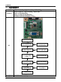
5. Exploded View & Part List
5. Exploded View & Part List
M0107
BN63-06356A
M0174
F001A
M0215
M0014
R001A
SB04A
SB01A
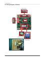
5-1. LS19CLYSB/XF - Exploded View (E1920N)
5-1
5. Exploded View & Part List
5-1-1. Parts List
Location No.
Code No.
Description & Specification
Q’ty
SA/SNA
F001A
BN96-13091A
ASSY COVER P-FRONT;Cobalt 18.5W,ABS,HB,B
1
SA
M0014
BN94-03397D
ASSY PCB MAIN-STZ;E1920N,STZ
1
SA
M0107
BN63-06355C
SHIELD-COVER;PLUM 18.5",SECC,T0.8,18.5"
1
SNA
M0174
BN44-00325B
IP BOARD;IP-22155A,PLUM15.6",18.5"w(2Lam
1
SA
M0215
BN07-00703A
LCD-PANEL;LTM185AT01,SS8YTSV,6bit Hi-FRC
1
SA
R001A
BN96-13090F
ASSY COVER P-REAR;Cobalt 18.5W,HIPS,HB,B
1
SA
SB01A
BN96-12853A
ASSY STAND P-BODY;COBALT,HIPS,BK23,ETCH
1
SA
SB04A
BN96-12816A
ASSY STAND P-BASE;COBALT 17~20,HIPS HB,B
1
SA
BN63-06356A
SHIELD-LAMP;PLUM 18.5'',SPTE,T0.3
1
SNA
5-2
Remark
5. Exploded View & Part List
5-2. LS19CLYSB/XF - Parts List (E1920N)
Service Bom (SA: SERVICE AVAILABLE, SNA: SERVICE NOT AVAILABLE)
Level
Location No.
Code No.
Description & Specification
Q’ty
0.1
R001A
..2
R001A
...3
BN90-02725B
ASSY COVER REAR;E1920N,BLACK,AMLCD
1
SNA
BN96-13090F
ASSY COVER P-REAR;Cobalt 18.5W,HIPS,HB,B
1
SA
W391
6003-000275
SCREW-TAPTYPE;BH,+,B,M3,L10,ZPC(BLK),S
WR
2
SA
...3
M0113
BN61-01581A
BRACKET-VESA;BI17/19BS,SECC,T1.0
2
SNA
...3
T0060
BN61-05331A
SPRING ETC;LAVENDER 23",SK5,T0.5
1
SNA
...3
CIS4
BN61-05332A
HOLDER-STAND;LAVENDER
23",ACETAL,WHITE
1
SNA
...3
M0111
BN63-05625A
COVER-STAND;LAVENDER 23W,BK23
1
SNA
...3
R001
BN63-06842E
COVER-REAR;Cobalt 18.5W,HIPS,HB,BK23,SIM
1
SNA
BN73-00170A
RUBBERFOOT;943BW,2043BW,RUBBER,8*8,1.5,
3
SNA
BN96-13846A
ASSY SHIELD P-LAMP;Cobalt 18.5",STPE,T0.
1
SNA
BN63-06356A
SHIELD-LAMP;PLUM 18.5'',SPTE,T0.3
1
SNA
BP63-00786A
GASKET;HLS6187WX/XAA,Conductive Adhesive
1
SNA
...3
M0126
...3
....4
....4
M0131
0.1
SA/SNA Remark
BN91-02220X
ASSY LCD;LS19CFNKFY/ZA,BN07-00703A
1
SNA
..2
M0215
BN07-00703A
LCD-PANEL;LTM185AT01,SS8YTSV,6bit Hi-FRC
1
SA
0.1
M0017
BN91-05223N
ASSY CHASSIS-STZ;E1920NX
1
SNA
..2
M0174
BN44-00325B
IP BOARD;IP-22155A,PLUM15.6",18.5"w(2Lam
1
SA
..2
M0014
BN94-03397D
ASSY PCB MAIN-STZ;E1920N,STZ
1
SA
...3
0202-001463
SOLDER-WIRE;LFC2-W3.0,-,D3,99.79Sn/0.2Cu
1.814
SNA
...3
0202-001608
SOLDER-WIRE FLUX;LFC7-107,D0.8,99.3Sn/0.
0.003
SNA
...3
0204-002420
SOLVENT;1M-1000,C3H70H,96
3.47
SNA
...3
0204-002607
FLUX;DF-234U,13%,14KG,Gravity 0.82
2.259
SNA
...3
3701-001510
CONNECTOR-DSUB;15P,3R,FEMAIL,STAMPED
PIN
1
SNA
3711-005847
CONNECTORHEADER;BOX,9P,1R,2MM,ANGLE,SN,
1
SNA
BN97-04137D
ASSY SMD;E1920N,STZ,BN94-03397D
1
SNA
0202-001477
SOLDER-CREAM;LST309M,D20~45um,96.5Sn/3A
0.462
SNA
...3
CN906
...3
....4
....4
DS01A
0401-001056
DIODE-SWITCHING;MMBD4148SE,100V,200m
A,SO
3
SA
....4
DR01A
0402-001614
DIODE-RECTIFIER;S1G,400V,1A,DO-214AC,TP
1
SA
....4
MZD1
0403-001411
DIODE-ZENER;5.49-5.73V,200mW,SOD-323,TP
8
SA
0403-001712
DIODE-ZENER;QZX363C6V8,6.47/7.14V,200mW,
1
SNA
PQ02
0501-002080
TR-SMALL
SIGNAL;2SC2412K,NPN,200mW,SC-59
1
SA
....4
Q409
0505-001165
FET-SILICON;Si3443CDV,P,-20V,+-4.4A,65mo
1
SA
....4
IC112
1103-000129
IC-EEPROM;24C02,2Kbit,256x8,SOP,8P,5x4mm
1
SA
....4
IC112
1103-001410
IC-EEPROM;S-24CS08AFJ-TB-1GE,8Kbit,1Kx8,
1
SA
....4
T0087
1203-006118
IC-POSI.FIXED REG.;S-1172B18-U5T1G,SOT-8
1
SA
....4
T0087
1203-006141
IC-POSI.FIXED REG.;S-1172B33-U5T1G,SOT-8
1
SA
IC109
1205-003895
IC-LCD CONTROLLER;SE919LMNT,QFP,64P,7x7
1
SA
....4
DR1
2007-000043
R-CHIP;1Kohm,1%,1/10W,TP,1608
4
SA
....4
CER02
2007-000071
R-CHIP;22ohm,5%,1/10W,TP,1608
2
SNA
....4
AR30
2007-000074
R-CHIP;100ohm,5%,1/10W,TP,1608
20
SA
....4
AVR51
2007-000083
R-CHIP;3Kohm,5%,1/10W,TP,1608
1
SNA
....4
....4
....4
5-3
5. Exploded View & Part List
Level
Location No.
Code No.
Description & Specification
....4
CER04
2007-000084
R-CHIP;4.7Kohm,5%,1/10W,TP,1608
2
SA
....4
MROP1
2007-000090
R-CHIP;10Kohm,5%,1/10W,TP,1608
14
SA
....4
AR108
2007-000097
R-CHIP;47Kohm,5%,1/10W,TP,1608
5
SA
....4
ARR2
2007-000102
R-CHIP;100Kohm,5%,1/10W,TP,1608
2
SA
....4
ZR24
2007-000109
R-CHIP;1Mohm,5%,1/10W,TP,1608
1
SNA
....4
KAR11
2007-000124
R-CHIP;2.2Kohm,5%,1/10W,TP,1608
3
SNA
....4
HR13
2007-000821
R-CHIP;390ohm,1%,1/10W,TP,1608
1
SNA
....4
ZR10
2007-001164
R-CHIP;75ohm,1%,1/10W,TP,1608
3
SNA
....4
R1
2007-002425
R-CHIP;1ohm,5%,1/10W,TP,1608
6
SNA
....4
C134
2203-000257
C-CER,CHIP;10nF,10%,50V,X7R,TP,1608
1
SA
....4
C409
2203-000292
C-CER,CHIP;0.01nF,5%,50V,C0G,1608
2
SA
....4
C3
2203-000384
C-CER,CHIP;0.015nF,5%,50V,C0G,1608
1
SNA
....4
ZC14
2203-000626
C-CER,CHIP;0.022nF,5%,50V,C0G,1608
1
SNA
....4
6MC22
2203-000975
C-CER,CHIP;47nF,10%,25V,X7R,TP,1608,-
6
SNA
....4
DC108
2203-005005
C-CER,CHIP;100nF,10%,16V,X7R,1608
24
SC
....4
PC11
2203-006141
C-CER,CHIP;1000nF,10%,16V,X5R,1608
2
SNA
....4
C125
2203-006361
C-CER,CHIP;10000nF,10%,10V,X5R,TP,2012
19
SC
....4
X202
2801-003773
CRYSTAL-SMD;12MHz,30ppm,28AAN,20pF,50oh
1
SA
....4
L2011
3301-001145
BEAD-SMD;60ohm,4516,TP,70ohm/45MHz,82o
hm
4
SNA
....4
T0568
3301-001407
BEAD-SMD;30ohm,1608,300mA,TP,,,0.4ohm
2
SNA
....4
AC510
3708-001150
CONNECTOR-FPC/FFC/PIC;30P,1mm,SMDA,SN,Y
1
SA
....4
HB01A
3711-005743
HEADER-BOARD TO
CABLE;BOX,5P,1R,1.25mm,A
1
SA
....4
T0077
BN41-01323A
PCB MAIN;PLUM B1630N,CEM-3,2,MP1.0,1.6,5
1
SNA
BN97-04136D
ASSY MICOM;E1920N,STZ,BN94-03250*
1
SNA
....4
SA/SNA Remark
.....5
IC115
1107-001580
IC-FLASH MEMORY;MX25L4005,4Mbit,512Kx8,S
1
SNA
..2
M0006
BN96-12503C
ASSY SHIELD P-COVER;PLUM 18.5",SECC,T0.8
1
SNA
BN61-05973A
STUD-PEM;PLUM23'',M4,D8,L20
2
SNA
...3
...3
M0107
BN63-06355C
SHIELD-COVER;PLUM 18.5",SECC,T0.8,18.5"
1
SNA
...3
T0073
AA63-01141A
GASKET-EMI;42D5,Conductive Fabric,1.5mm,
2
SNA
...3
M0131
BN63-00049A
GASKET;RB17AS,Conductive Fabric,1.5MM,10
3
SNA
...3
M0114
BN61-02500A
HOLDER-WIRE;NYLON6.6,NATURAL
1
SNA
..2
T0081
6001-002408
SCREW-MACHINE;BH,+,WT,M4,L12,ZPC(WHT
),SW
2
SA
..2
M0081
6003-000264
SCREW-TAPTYPE;PWH,+,,B,M3,L6,ZPC(WHT),S
2
SA
..2
M0214
BN96-02854W
ASSY CABLE P-FLAT CABLE;MCKINLEY,FLAT
CA
1
SA
BN91-05285A
ASSY SHIELD;E1920
1
SNA
0.1
..2
CIS1
0.1
..2
CCM1
0.1
..2
T0214
..2
..2
5-4
Q’ty
T0524
BN74-00021A
TAPE-FILAMENT;Filament tape,clear,#8915,
0.3
SNA
BN92-05486D
ASSY LABEL;Cobalt, BLACK
1
SNA
BN68-01570A
LABEL RATING;ALL,SS,PE,T0.05,90,45,Dark
1
SNA
BN92-05547L
ASSY P/MATERIAL;S19S3,W/W
1
SNA
0203-001595
TAPE-OPP MASKING;OPP-2,0.075,75,800M,CLR
1.31
SNA
6902-000061
BAG AIR;LDPE,T0.2,W500,L1000,TRP,370.000
1
SNA
6902-000241
BAG PE;HDPE/NITRON,T0.5/T0.012,W600,L600
1
SNA
..2
6902-000379
BAG AIR;LDPE,T0.2,W1000,L1800,TRP,1260.0
1
SNA
..2
6902-000604
BAG WRAPPING;LDPE,T0.02,W500,L10000,TRP,
1.5
SNA
..2
6902-000609
BAG ROLL;LDPE,T0.05,W2400,L1000,TRP,30.0
0.02
SNA
..2
AA69-00243G
PAD-PLATE;CB SW-2,YEL,990,990,-,-,SP43J5
1
SNA
5. Exploded View & Part List
Level
Location No.
Code No.
Description & Specification
Q’ty
..2
T0527
BH68-40364A
LABEL-SUMMARY;G52,G72,ART,100G,WHT,BL
K,W
1
SNA
BH69-00457A
PACKING INNER-00,PAD;COMM,T3.0,1130,1180
1
SNA
BN68-00129A
LABEL SHIPPING-00;LABEL SHIPPING,ART-PAP
1
SNA
..2
BN69-00139L
PALLETPACKING;LN17HO,WOODEN,W:1030,D:10
1
SNA
..2
BN69-00391Y
PAD-ANGLE;CB,T5,W2100,L50,YEL,403g
1
SNA
..2
BN69-04618A
CUSHION-SET;COBALT18.5",SIMPLE,EPS,T0.01
1
SNA
..2
..2
T0527
0.1
SA/SNA Remark
BN92-05761L
ASSY BOX;E1920NX,LS19CLYSB/XF
1
SNA
BH68-00329D
LABEL BAR CODE-02;NO CE,NO WT`Y,MPRII,LA
1
SNA
..2
BH68-00651U
LABEL BOX-00;ALL MODEL,MOJO
90G,90,95,WH
1
SNA
..2
BN68-02258K
LABEL-STICKER
HIC;MODEL7,CHINA,MOJO,80G,
1
SNA
..2
BN69-04812A
BOX-01,SET;Cobalt18.5"(SIMPLE),PAPER,SW,
1
SNA
..2
T0077
0.1
ACCE1
BN92-05916B
ASSY ACCESSORY;LS20CLYSB/XF
1
SNA
..2
EC29
BN39-00244H
CBF SIGNAL-D-SUB TO D-SUB;D-sub cable,15
1
SA
..2
SB04A
BN96-12816A
ASSY STAND P-BASE;COBALT 17~20,HIPS
HB,B
1
SA
...3
T0524
6902-000109
BAG PE;HDPE,T0.015,W350,L430,TRP,28,2,4.
1
SNA
...3
CIS4
BN61-01717A
HOLDER-STAND;BIZET,NI PLT,CH,+,M4,L11(5)
1
SNA
...3
BN63-06716A
COVER-STAND BASE;COBALT
17~20,HIPS,HB,BK
1
SNA
...3
BN68-02691A
MANUAL FLYER-STAND;COBALT,Mojo 80g,148,2
1
SNA
...3
BN68-02822G
LABEL-STICKER;W/W,ART PAPER,T0.05,50,10,
1
SNA
6
SNA
SA
...3
AR011
BN73-00077A
RUBBER FOOT;MATISSE,BUMPON,#13.5,T2.0
,60
..2
SB01A
BN96-12853A
ASSY STAND
P-BODY;COBALT,HIPS,BK23,ETCH
1
...3
W392
6003-000282
SCREW-TAPTYPE;BH,+,-,B,M3,L8,ZPC(BLK),SW
2
SA
...3
T0524
6902-000023
BAG PE;LDPE,T0.08,W150,L120,TRP,1.650g
1
SNA
...3
BN61-06067A
STAND-BAR;COBALT 21.5,HIPS,BK23
1
SNA
....4
BN61-06068A
STAND-BAR IN;COBALT,HIPS,BK23,IN
1
SNA
...3
BN61-06334A
BRACKET-PLATE;COBALT,SECC,1.0,SIMPLE
1
SNA
...3
BN68-02822J
LABEL-STICKER;W/W,ART PAPER,T0.05,50,10,
1
SNA
SA
..2
ACCE1
BN96-13553Y
ASSY ACCESSORY;LS17CLASB/XF
1
...3
T0268
3903-000455
CBF-POWER CORD;DT,CN,IP3/Y(A),IEC320 C13
1
SA
...3
T0524
6902-000110
BAG PE;LDPE,T0.05,W250,L400,TRP,28,2,9.2
1
SNA
...3
T0527
AA68-00764A
LABEL-PASSING;SAMSUNG ALL,ART
PAPER,CLR,
1
SNA
...3
T0527
BN68-00513A
LABEL-E,PASS;ALL MODEL,YUPO(110G),50X15,
1
SNA
...3
BN68-01118D
MANUAL-TCO 5.0 CARD;COMM,W/W,Mojo
80g,21
1
SNA
...3
BN68-01789A
MANUAL FLYER-WARRANTY CARD;Chinese,Art
1
1
SNA
...3
BN68-02528A
MANUAL FLYER-CHINA
MANUAL;Cobalt,SyncMas
1
SNA
0.1
BN90-02693A
ASSY COVER FRONT;E1920,BLACK
1
SNA
F001A
BN96-13091A
ASSY COVER P-FRONT;Cobalt 18.5W,ABS,HB,B
1
SA
...3
F001
BN63-06843A
COVER-FRONT;Cobalt 18.5W,ABS,HB,BK23,SIM
1
SNA
...3
AL093
BN67-00281A
LENS-LED;Cobalt Project,PC CLEAR,TP26
1
SNA
BN68-02382B
LABEL-TCO5.0,ENERGYSTAR;TCO5.0,ENERGY-S
1
SNA
BN64-01309A
KNOB-FUNCTION;Cobalt Project,ABS,BK23
1
SNA
..2
...3
...3
M0007
5-5
5. Exploded View & Part List
Level
Location No.
Code No.
Description & Specification
Q’ty
SA/SNA Remark
...3
FB01A
BN96-13682E
ASSY BOARD
P-FUNCTION;Cobalt,FUNCTION,20
1
SA
....4
BN94-03497D
ASSY PCB FUNCTION-BN9613682E;COBALT,BN9
1
SNA
.....5
0202-001463
SOLDER-WIRE;LFC2-W3.0,-,D3,99.79Sn/0.2Cu
1.814
SNA
.....5
0202-001608
SOLDER-WIRE FLUX;LFC7-107,D0.8,99.3Sn/0.
0.003
SNA
.....5
0204-002420
SOLVENT;1M-1000,C3H70H,96
3.47
SNA
.....5
0204-002607
FLUX;DF-234U,13%,14KG,Gravity 0.82
2.259
SNA
.....5
EC13
BN39-01298D
LEAD CONNECTOR;Cobalt,UL 1061 #28,UL/CSA
1
SA
.....5
T0174
BN97-04306A
ASSY SMD;COBALT, FUNCTION
1
SNA
0202-001477
SOLDER-CREAM;LST309M,D20~45um,96.5Sn/3A
0.462
SNA
......6
......6
L0405
0601-001896
LED;SMD,BLUE,1.6x0.8x0.4mm,470,1.6x0.8x0
1
SA
......6
AHR40
2007-000088
R-CHIP;7.5Kohm,5%,1/10W,TP,1608
2
SNA
......6
KAR11
2007-000124
R-CHIP;2.2Kohm,5%,1/10W,TP,1608
2
SNA
......6
T0313
3404-001379
SWITCH-TACT;12V,50mA,250gf,4.9x4.9x1.5mm
6
SA
3711-005743
HEADER-BOARD TO
CABLE;BOX,5P,1R,1.25mm,A
1
SA
BN41-01400B
PCB SUB-FUNCTION;Cobalt(all),FR-4,2,1.1,
1
SNA
......6
......6
5-6
HB01A
1. Precautions
1. Precautions
1-1. Safety Precautions
Follow these safety, servicing and ESD precautions to prevent damage and to protect against potential hazards such as
electrical shock.
1-1-1. Warnings
1. For continued safety, do not attempt to modify the circuit board.
2. Disconnect the AC power and DC power jack before servicing.
1-1-2. Servicing the LCD Monitor
1. When servicing the LCD Monitor, Disconnect the AC line cord from the AC outlet.
2. It is essential that service technicians have an accurate voltage meter available at all times. Check the calibration of
this meter periodically.
1-1-3. Fire and Shock Hazard
Before returning the monitor to the user, perform the following safety checks:
1. Inspect each lead dress to make certain that the leads are not pinched or that hardware is not lodged between the
chassis and other metal parts in the monitor.
2. Inspect all protective devices such as nonmetallic control knobs, insulating materials, cabinet backs, adjustment and
compartment covers or shields, isolation resistorcapacitor networks, mechanical insulators, etc.
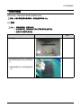
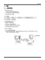
3. Leakage Current Hot Check (Figure 1-1):
WARNING : Do not use an isolation transformer during this test.
Use a leakage current tester or a metering system that complies with American National Standards Institute (ANSI
C101.1, Leakage Current for Appliances), and Underwriters Laboratories (UL Publication UL1410, 59.7).
(READING SHOULD)
NOT BE ABOVE 0.5mA
LEAKAGE
CURRENT
TESTER
DEVICE
UNDER
TEST
TEST ALL
EXPOSED METAL
SURFACES
2-WIRE CORD
*ALSO TEST WITH
PLUG REVERSED
(USING AC ADAPTER
PLUG AS REQUIRED)
EARTH
GROUND
Figure 1-1. Leakage Current Test Circuit
4. With the unit completely reassembled, plug the AC line cord directly into a 120V AC outlet. With the unit’s AC switch
first in the ON position and then OFF, measure the current between a known earth ground (metal water pipe, conduit,
etc.) and all exposed metal parts, including: metal cabinets, screwheads and control shafts.
The current measured should not exceed 0.5 milliamp.
Reverse the power-plug prongs in the AC outlet and repeat the test.
1-1-4. Product Safety Notices
Some electrical and mechanical parts have special safetyrelated characteristics which are often not evident from visual
inspection. The protection they give may not be obtained by replacing them with components rated for higher voltage,
wattage, etc. Parts that have special safety characteristics are identified by
on schematics and parts lists. A substitute
replacement that does not have the same safety characteristics as the recommended replacement part might create
shock, fire and/or other hazards. Product safety is under review continuously and new instructions are issued whenever
appropriate.
1-1
1. Precautions
1-2. Servicing Precautions
WARNING: An electrolytic capacitor installed with the wrong polarity might explode.
Caution:
Before servicing units covered by this service manual, read and follow the Safety Precautions section of
this manual.
Note:
If unforeseen circumstances create conflict between the following servicing precautions and any of the
safety precautions, always follow the safety precautions.
1-2-1 General Servicing Precautions
1. Always unplug the unit’s AC power cord from the AC power source and disconnect the DC Power Jack before
attempting to:
(a) remove or reinstall any component or assembly, (b) disconnect PCB plugs or connectors, (c) connect a test
component in parallel with an electrolytic capacitor.
2. Some components are raised above the printed circuit board for safety. An insulation tube or tape is sometimes
used. The internal wiring is sometimes clamped to prevent contact with thermally hot components. Reinstall all such
elements to their original position.
3. After servicing, always check that the screws, components and wiring have been correctly reinstalled. Make sure that
the area around the serviced part has not been damaged.
4. Check the insulation between the blades of the AC plug and accessible conductive parts (examples: metal panels,
input terminals and earphone jacks).
5. Insulation Checking Procedure: Disconnect the power cord from the AC source and turn the power switch ON.
Connect an insulation resistance meter (500 V) to theblades of the AC plug.
The insulation resistance between each blade of the AC plug and accessible conductive parts (see above) should be
greater than 1 megohm.
6. Always connect a test instrument’s ground lead to the instrument chassis ground before connecting the positive lead;
always remove the instrument’s ground lead last.
1-3. Static Electricity Precautions
Some semiconductor (solid state) devices can be easily damaged by static electricity. Such components are commonly
called Electrostatically Sensitive Devices (ESD). Examples of typical ESD are integrated circuits and some field-effect
transistors. The following techniques will reduce the incidence of component damage caused by static electricity.
1. Immediately before handling any semiconductor components or assemblies, drain the electrostatic charge from your
body by touching a known earth ground. Alternatively, wear a discharging wrist-strap device. To avoid a shock hazard,
be sure to remove the wrist strap before applying power to the monitor.
2. After removing an ESD-equipped assembly, place it on a conductive surface such as aluminum foil to prevent
accumulation of an electrostatic charge.
3. Do not use freon-propelled chemicals. These can generate electrical charges sufficient to damage ESDs.
4. Use only a grounded-tip soldering iron to solder or desolder ESDs.
5. Use only an anti-static solder removal device. Some solder removal devices not classified as “anti-static” can generate
electrical charges sufficient to damage ESDs.
6. Do not remove a replacement ESD from its protective package until you are ready to install it. Most replacement ESDs
are packaged with leads that are electrically shorted together by conductive foam, aluminum foil or other conductive
materials.
7. Immediately before removing the protective material from the leads of a replacement ESD, touch the protective
material to the chassis or circuit assembly into which the device will be installed.
Caution: Be sure no power is applied to the chassis or circuit and observe all other safety precautions.
8. Minimize body motions when handling unpackaged replacement ESDs. Motions such as brushing clothes together,
or lifting your foot from a carpeted floor can generate enough static electricity to damage an ESD.
1-2
1. Precautions
1-4. Installation Precautions
1. For safety reasons, more than two people are required for carrying the product.
2. Keep the power cord away from any heat emitting devices, as a melted covering may cause fire or electric shock.
3. Do not place the product in areas with poor ventilation such as a bookshelf or closet. The increased internal
temperature may cause fire.
4. Bend the external antenna cable when connecting it to the product. This is a measure to protect it from being exposed
to moisture. Otherwise, it may cause a fire or electric shock.
5. Make sure to turn the power off and unplug the power cord from the outlet before repositioning the product. Also check
the antenna cable or the external connectors if they are fully unplugged. Damage to the cord may cause fire or electric
shock.
6. Keep the antenna far away from any high-voltage cables and install it firmly. Contact with the highvoltage cable or the
antenna falling over may cause fire or electric shock.
7. When installing the product, leave enough space (10cm) between the product and the wall for ventilation purposes.
A rise in temperature within the product may cause fire.
1-3
1. Precautions
Memo
1-4
2. Product specifications
2. Product specifications
2-1. Feature & Specifications
Feature
Model
E1720NR / E1720NRX
E1920N / E1920NX
Brightness(Typical)
250 cd/m2
Response Time(Typical)
5ms
Contrast Ratio(Typical)
DC 50000:1
(Typ.500:1)
E1920NR / E1920NRX
Viewing Angle
(Horizontal/Vertical)
170˚/160˚ (CR>10)
Stand by Power(DPMS)
<0.3W
Special Features
MagicBright3, MagicEco, MagicAngle, Off timer, Image Size,
Color Effect,Customized key, Windows Vista Basic
Specifications
Model
E1720NR / E1720NRX
E1920N / E1920NX
E1920NR / E1920NRX
TFT-LCD panel, RGB vertical stripe, normally white transmissive
LCD Panel
17”Normal
0.264 mm(H) x 0.264 mm(V)
pixel pitch
18.5”Wide
0.3 mm(H) x 0.3 mm(V)
pixel pitch
Scanning Frequency
Horizontal : 30 ~ 81 kHz
Vertical : 56 ~ 75 Hz
Color Supported
16.7M
19”Normal
0.294 mm(H) x 0.294 mm(V)
pixel pitch
Resolution
1280 x 1024
1360 x 768
1280 x 1024
Input Signal
17”Normal Analog
18.5” Analog
19”Normal Analog
Separate H/V sync, Composite H/V, Sync-on-Green
Level:TTL level
Input Sync. Signal
Maximum Pixel Clock
135 MHz
89 MHz
135 MHz
Active Display
(Horizontal/Vertical)
337.92(H) x 270.336(V)
409.8(H) x 230.4(V)
376.32(H) x 301.056(V)
AC power voltage & Frequency
AC 110~130V, 60Hz & AC 200~240V, 50Hz
Power consumption
Less than 22W
Less than 22W
Less than 24W
Dimension Set
(W x H x D)
373.5 x 395.9 x 179.8mm
443.4 x 355 x 179.8mm
417.2 x 426.4 x 179.8mm
Weight
3.5Kg
3.45Kg
4.2Kg
Environmental Considerations
Operating Temperature: 10˚C ~ 40˚C(50˚F ~ 104˚F)
Operating Humidity : 10% ~ 80%
Operating Temperature: -25˚C ~ 45˚C(-13˚F ~ 113˚F)
Operating Humidity: 5% ~ 90%
Note: Designs and specifications are subject to change without prior notice.
2-1
2. Product specifications
Feature
Model
E1920NW / E1920NWX
E2020N / E2020NX
E2220N / E2220NX
Brightness(Typical)
300 cd/m2
250 cd/m2
300 cd/m2
Response Time(Typical)
Contrast Ratio(Typical)
Viewing Angle
(Horizontal/Vertical)
5ms
DC 70000:1
(Typ. 1000:1)
DC 50000:1
(Typ. 1000:1)
160˚/160˚ (CR>10)
DC 70000:1
(Typ. 1000:1)
170˚/160˚ (CR>10)
Stand by Power(DPMS)
<0.3W
Special Features
MagicBright3, MagicEco, MagicAngle, Off timer, Image Size,
Color Effect,Customized key, Windows Vista Basic
Specifications
Model
E1920NW / E1920NWX
E2020N / E2020NX
E2220N / E2220NX
TFT-LCD panel, RGB vertical stripe, normally white transmissive
LCD Panel
19”Wide
20” Wide
0.2835 mm(H) x 0.2835 mm(V) 0.2768 mm(H) x 0.2768 mm(V)
pixel pitch
pixel pitch
Scanning Frequency
Horizontal : 30 ~ 81 kHz
Vertical : 56 ~ 75 Hz
Color Supported
16.7M
Resolution
1440 x 900
1600 x 900
1920 x 1080
Input Signal
19” Analog
20” Analog
21.5” Analog
Separate H/V sync, Composite H/V, Sync-on-Green
Level : TTL level
Input Sync. Signal
Maximum Pixel Clock
137 MHz
150 MHz
162 MHz
Active Display
(Horizontal/Vertical)
408.24 mm x 255.15 mm
442.8 mm x 249.075 mm
476.64 mm x 268.11 mm
AC power voltage & Frequency
AC 110~130V, 60Hz & AC 200~240V, 50Hz
Power consumption
Less than 39W
Less than 28W
Less than 50W
Dimension Set
(W x H x D)
443.0 x 375.0 x 179.8mm
475.1 x 368.95 x 179.8mm
513.2 x 388.5 x 179.8mm
Weight
3.6Kg
3.95Kg
4.1Kg
Environmental Considerations
Operating Temperature: 10˚C ~ 40˚C(50˚F ~ 104˚F)
Operating Humidity : 10% ~ 80%
Operating Temperature: -25˚C ~ 45˚C(-13˚F ~ 113˚F)
Operating Humidity: 5% ~ 90%
Note: Designs and specifications are subject to change without prior notice.
2-2
21.5” Wide
0.24825 mm(H) x 0.24825 mm(V)
pixel pitch
2. Product specifications
Feature
Model
E2220NW
Brightness(Typical)
300 cd/m2
Response Time(Typical)
5ms
Contrast Ratio(Typical)
DC 70000:1
(Typ. 1000:1)
Viewing Angle
(Horizontal/Vertical)
170˚/160˚ (CR>10)
Stand by Power(DPMS)
<0.3W
Special Features
MagicBright3, MagicEco, MagicAngle, Off timer, Image Size,
Color Effect,Customized key, Windows Vista Basic
Specifications
Model
LCD Panel
E2220NW
TFT-LCD panel, RGB vertical stripe, normally white transmissive
22”Wide, 0.282 mm(H) x 0.282 mm(V) pixel pitch
Scanning Frequency
Horizontal : 30 ~ 81 kHz
Vertical : 56 ~ 75 Hz
Color Supported
16.7M
Resolution
1680 x 1050
Input Signal
22” Analog
Input Sync. Signal
Separate H/V sync, Composite H/V, Sync-on-Green
Level : TTL level
Maximum Pixel Clock
146 MHz
Active Display
(Horizontal/Vertical)
473.76 mm x 296.1 mm
AC power voltage & Frequency
AC 110~130V, 60Hz & AC 200~240V, 50Hz
Power consumption
Less than 50W
Dimension Set
(W x H x D)
510.7 x 421.35 x 179.8mm
Weight
4.55Kg
Environmental Considerations
Operating Temperature: 10˚C ~ 40˚C(50˚F ~ 104˚F)
Operating Humidity : 10% ~ 80%
Operating Temperature: -25˚C ~ 45˚C(-13˚F ~ 113˚F)
Operating Humidity: 5% ~ 90%
Note: Designs and specifications are subject to change without prior notice.
2-3
2. Product specifications
2-2. Spec Comparison to the Old Models
Model
E1720NR/ E1720NRX/ E1920N/ E1920NX/
E1920NR/ E1920NRX/ E1920NW/
E1920NWX/ E2020N/ E2020NX/ E2220N/
E2220NX/ E2220NW
743A/943SN/943N/943NW
2043SN/2243SN/2243NW
1280 x 1024
(E1720NR/E1920NR)
1280 x 1024
(743A/943N)
1360 x 768
(E1920N)
1360 x 768
(943SN)
1440 x 900
(E1920NW)
1440 x 900
(943NW)
1600 x 900
(E2020N)
1600 x 900
(2043SN)
1920 x 1080
(E2220N)
1920 x 1080
(2243SN)
1680 x 1050
(E2220NW)
1680 x 1050
(2243NW)
Analog
Analog
5ms
5ms
160˚/160˚ (CR>10)
(E1920NW)
160˚/160˚ (CR>10)
(943NW)
170˚/ 160˚ (CR>10)
(E1720NR/E1920N/E1920NR
E2020N/E2220N/E2220NW)
170˚/ 160˚ (CR>10)
(743A/943SN/943N
2043SN/2243SN/2243NW)
250 m²
(E1720NR/E1920N/E1920NR/E2020N)
250 m²
(743A/943SN/943N/2043SN)
300 m²
(E1920NW/E2220N/E2220NW)
300 m²
(943NW/2243SN/2243NW)
50,000:1(DC)
(E1720NR/E1920N/E1920NR/E2020N)
50,000:1(DC)
(743A/943SN/943N/2043SN)
70,000:1(DC)
(E1920NW/E2220N/E2220NW)
70,000:1(DC)
(943NW/2243SN/2243NW)
5 Step
7 Step
Design
Resolution
Input
Response Time
Viewing Angle
Brightness
Contrast
MagicBright
2-4
2. Product specifications
Model
Feature
E1720NR/ E1720NRX/ E1920N/ E1920NX/
E1920NR/ E1920NRX/ E1920NW/
E1920NWX/ E2020N/ E2020NX/ E2220N/
E2220NX/ E2220NW
743A/943SN/943N/943NW
2043SN/2243SN/2243NW
MagicBright3
MagicEco
MagicAngle
Off timer
Image Size
Color Effect
MagicBright3
Off timer
Image Size
Color Effect
*Color Effect
- Grey scale: Images are displayed in a grey tone on the screen.
- Green: Images are displayed in a green tone on the screen.
- Aqua: Images are displayed in a blue tone on the screen.
- Sepia: Images are displayed in a brown tone on the screen.
Image Size : If the resolution is not wide resolution, this option allows the screen size to be selected as normal or wide.
*MagicAngle
- Lean Back Mode1: Select when viewing from a slightly lower angle.
- Lean Back Mode2: Select when viewing from the bottom.
- Standing Mode: Select when viewing from the top.
- Side Mode: Select when viewing from the left or right.
- Custom: When <Custom> is selected, settings for <Lean Back Mode 1> is applied by default.
User can set suitable picture quality as needed.
*MagicEco
- 100%: the power consumption is 100% of Default Setting.
- 75%: the power consumption is 75% of Default Setting.
- 50%: the power consumption is 50% of Default Setting.
2-5
2. Product specifications
2-3. Accessories
Product
2-6
Description
Ccde. No
Quick Setup Guide
BN68-02508A
Warranty Card
(Not available in all locations)
BN68-00226R
User’s Guide,
Monitor Driver,
Natural Color Pro Software
BN59-00990A
D-sub Cable
1,500mm(1.5M)
BN39-00244H
Power Cord
1,830mm(1.8M)
3903-000452
Cleaning Cloth
160mm x 120mm
(option for high-glossy Models)
BN63-02368B
Remark
Samsung Electronics
Service center
! "#$"%&'()* +,-(. y
/0 ! 1234(.567 834(.567 34(.567
y
9: ;<= 834(.567
y
9: 34(.567
>?@A
B "CD)
@E F GHIJKLMNO !"#$ %&' ( )
*+!",-./012!"34 56
78
9 :;<=6 PQ
RS ()TU
;%& &*V
WXYZ[W
\] ()TU %& &*V WXYZ[W
+, &*^%&_` +, &*ab$"%&c=5d +,=5e%&Iab$"%&c' 5d 23<=>
%&'( 56
!"#$
)
./0*+ )
*+,-
./04567)8967
:; )
1
./0*.23 )
?@
78
9 :;<=6 23)
23
f
PQ
PQgh$ij
TUGHIV mnabop
qGHrst %
uv wx &*yz{|}%&
~e()A=5M
opVJyz h$ij {$"%& &*
-2
opMc=5 kl
rsta!
=5^
M
opVGH ^l
+,^kab$ Z'r^ ¡¢£¤GHI £¤¥k¦§¨ M
M >? ©ª «¬ª "C@
F
®
¯°() U±()
5²^³´µ
+, " ¶·¸¹ " M ºg»¼M +,½pab¾¿^ #" ÀÁM M²Â¯ÃAÄ "! »ÅM 5ÀÁV]Æ ÇÈÉÊ(ËÌÍÎÏÐÑ¿xÒý^ $%" ÓÔ
Ö-ÖAM»Å ×H " MÓÔg " Õ7
A%&I
Ú(Û GHIØÙ
#!
" SÜI
%&GHI
op(Û +,ÀÁÝ´
M " ²+, #" ÀÁÝ´g+Þg M " ©ªg«¬ªc "ß@gD)@ F !WGH " 12 Ù® WGH12 àáâãÙ¯°() r
äMopåxæç×è^² rJéÆêëìV¡ í Dîï
ð^cñ
ò^ 5=oó
ôõKLô
ôõö÷ô
øù
ßúIûü
ýL þ ôõ>?
#$&'( Ý´
#$&'( +Þg
p
þ îcU{¯
=5V
=5² ôõ=5µA
>?
þ F
5= ")
' Jÿ V¡oóJîc »¼ÿ M " »Å
]Æ " SÜI #! Ý´{
TU*+,ú ôõ TU " Õ7 ôõA"C*#,
þ *"ß,
þ M
pA
"C@ ÚMº»Å² M»¼»Å ÈÓc
M #" ȁ
TU -./01$231 ²+,ô
ô N
!ý
4$5½pôõ
ÉÊ
KL+
"Cî
ÑÕ7
þ
ôõ #" ÀÁÕ7
²TU
6
þ
KL
þ
äÓg+Þ:²
¯ÃAU±
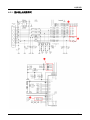
6. Wiring Diagram
6. Wiring Diagram
6-1. Wiring Diagram - Main Board
E1720NR / E1720NRX / E1920NR / E1920NRX / E1920NW / E1920NWX /
E2020N / E2020NX / E2220N / E2220NX / E2220NW
6-1
6. Wiring Diagram
E1920N / E1920NX
6-2
6. Wiring Diagram
NO
Block
1
Scaler
IC200
2
Role Description
The ADC, TMDS, Scaling and Controller are integrated on a
single chip.
Remarks
SE919LM-NT
FLASH MEMORY Stores the firmware for the Scaler. The information can be
IC401
updated.
3
EEPROM
IC402
Stores the OSD, Timing etc.
4
EEPROM
IC202
Stores the EDID data.
5
Regulator
IC601, IC602
The IC for a stable DC power supply.
NVRAM
24C08
24C02
S-1172B33-U5T1G
S-1172B18-U5T1G
6-3
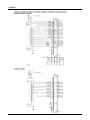
6. Wiring Diagram
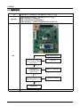
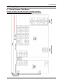
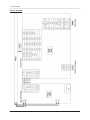
6-2. Wiring Diagram - IP Board
LVDS Connector
(Connect to Panel)
IP board
CN400
CN600
IC400
CN200
CN401
Function Connector
(Connect to IP-Board)
RGB Connector
(Connect to PC)
6-4
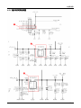
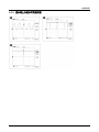
6. Wiring Diagram
6-3. Connector Functions
Connector
CN802 CN600
Functions
Supplies 5V from the power board to the main board and transmits the PWM output from the
power board to the inverter.
*When a problem occurs: The No Power and Blank Screen errors may occur.
CN1 ~ CN4 In
Transmits the lamp current (6mA ~ 7mA) generated in the inverter to the lamp of the panel.
* When a problem occurs: The Blank Screen error may occur.
CN200
VGA signal input terminal
* When a problem occurs: The No RGB output error may occur.
CN400
Transmits the LVDS signals from the main board to the panel.
* When a problem occurs: The Blank screen and No Power errors may occur.
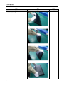
6-4. Cables
Use
LVDS 30P FFC cable
Code
BN96-02854X(E1720NR/ E1720NRX)
Photo
BN96-02854W
Code
(E1920N/ E1920NX/E1920NW/
E1920NWX/E2020N/ E2020NX)
Photo
Code
BN96-02854Y(E1920NR/ E1920NRX/
E2220N/ E2220NX)
Photo
Code
BN96-12447G(E2220NW)
Photo
6-5
6. Wiring Diagram
Memo
6-6