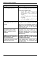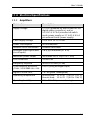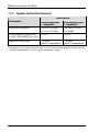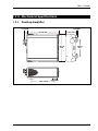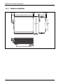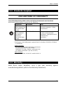
1
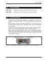
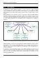
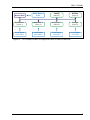
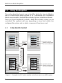
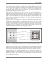
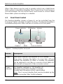
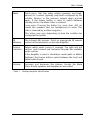
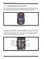
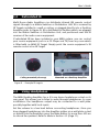
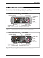
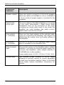
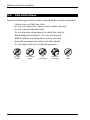
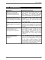
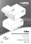
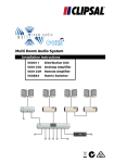
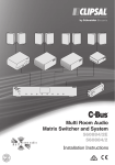
Multi Room Audio Amplifier
User’s Guide
560125D Remote Amplifier
560125R
Desktop Amplifier
POWER
MUTE
© Copyright Clipsal Integrated Systems Pty Ltd 2005. All rights reserved. This
material is copyright under Australian and international laws. Except as permitted
under the relevant law, no part of this work may be reproduced by any process
without prior written permission of and acknowledgement to Clipsal Integrated
Systems Pty Ltd.
Clipsal is a registered trademark of Clipsal Australia Pty Ltd.
The information in this manual is provided in good faith. Whilst Clipsal Integrated
Systems (CIS) has endeavoured to ensure the relevance and accuracy of the
information, it assumes no responsibility for any loss incurred as a result of its use.
CIS does not warrant that the information is fit for any particular purpose, nor does
it endorse its use in applications which are critical to the health or life of any
human being. CIS reserves the right to update the information at any time without
notice.
V1.0 Dec 2005
Contents
1.0
Product Range
5
2.0
Important Notes
5
3.0
Description
6
4.0
Using the Amplifier
8
8
4.1
C-Bus Switch Control
4.2
Front Panel Control
10
4.3
Desktop Amplifier Remote Control
12
5.0
Reticulated IR
13
6.0
Using Headphones
13
7.0
Local Input
14
8.0
Rear Panel Connections
15
9.0
Care Instructions
18
10.0
Troubleshooting
19
11.0
Electrical Specifications
21
12.0
11.1
Amplifiers
21
11.2
System Audio Performance
22
Mechanical Specifications
23
12.1
Desktop Amplifier
23
12.2
Remote Amplifier
24
13.0
Standards Complied
25
14.0
Warranty
25
Multi Room Audio Amplifier
4
User’s Guide
1.0
Product Range
560125D
Multi Room Audio Amplifier (Desktop Mounting)
560125R
Multi Room Audio Amplifier (Remote Mounting)
2.0
•
•
•
•
Important Notes
The Multi Room Audio (MRA) Amplifiers are suitable for operation in
moderate to tropical climates. The units should be mounted indoors
only.
MRA Amplifiers disperse heat through the fins on their sides. Ensure
at least 50 mm of free space is available at each side of the Amplifier
for ventilation.
Only use a Clipsal approved power supply to power an MRA Amplifier.
Failure to do so may damage the unit, and void the warranty.
Both C-Bus and digital audio cables are terminated with RJ45
connectors. Never plug either of these cables into the wrong socket.
C-Bus cable is pink. The RJ45 sockets on the rear of the Desktop Amp
are identified in Figure 1.
Digital audio
L
C-Bus
DIGITAL
AUDIO IN
R
ZONE
LOCAL
OUT L
IN
EXTERNAL
IR
OPTICAL
TARGET
IN
Unit
R
POWER
DIGITAL
AUDIO OUT
Figure 1 – Never plug a C-Bus cable into a digital audio socket or vice versa
5
Multi Room Audio Amplifier
3.0
Description
A Multi Room Audio (MRA) Amplifier is used as part of a C-Bus enabled
audio distribution system. It provides audio which is controllable via C-Bus
wall switches and other C-Bus devices such as the C-Touch Colour Touch
Screen.
MRA Amplifiers are typically used in conjunction with the MRA Matrix
Switcher. A Matrix Switcher distributes audio from multiple sources (such
as a radio, TV and CD player) to up to eight zones. (A zone consists of one
or more MRA Amplifiers). An example of this configuration is shown in
Figure 2.
Local Input
DVD Player
Distributed Audio Sources
Radio, TV, CD Player
Bedroom 1
(Zone 1)
Garage
(Zone 6)
Bedroom 2
(Zone 2)
Kitchen
(Zone 5)
Bedroom 3
(Zone 3)
Family
(Zone 4)
Local Input
Computer
Local Input
Computer
Figure 2 – An example audio distribution configuration using a Matrix Swticher
MRA Amplifiers can also be used without a Matrix Switcher. In this case a
Distribution Unit is used to distribute audio from a single source (such as a
radio) to one or more MRA Amplifiers. An example of this configuration is
shown in Figure 3.
In addition to the distributed audio, each MRA Amplifier accepts a local
audio source (local input). This allows you to connect audio from a source
such as a PC or portable audio player, which will be available to the
specific Amplifier only.
6
User’s Guide
Distr’n Unit
Audio Source
Radio
Family
(Zone 4)
Kitchen
(Zone 5)
Bedroom 1
(Zone 1)
Bedroom 2
(Zone 2)
Bedroom 3
(Zone 3)
Garage
(Zone 6)
Local Input
DVD Player
Local Input
MP3 Player
Local Input
Computer
Local Input
CD Player
Figure 3 – An example audio configuration with no Matrix Switcher
7
Multi Room Audio Amplifier
4.0
Using the Amplifier
This section describes how to use an Amplifier which has been installed as
part of a Multi Room Audio system, or as a standalone unit. Installation
details are provided in the Multi Room Audio System Installation Manual.
There are several methods in which a Multi Room Audio system can be
controlled. The methods will vary depending on how the installer has
configured the system and on which components have been used.
4.1
C-Bus Switch Control
Lights
Bass
Curtains
Volume
TV
Lights
Curtains
Volume
Radio
15:28
ChannelChannel+
15:31
1
Pressing the input source
button changes the source
15:30
Treble
Selecting
Page 2
2
Bass
Treble
AM/FM
Dynamic Control
buttons change with
the source selection
Station
1
Selecting
Page 2
Dynamic Control
buttons change with
the source selection
15:29
2
Figure 4 – Example of a DLT switch used to control one zone in an MRA system
8
User’s Guide
The most common method of control is via C-Bus switches such as the
Neo, Ulti Saturn and Dynamic Labelling Technology (DLT) range. Buttons
on a C-Bus wall switch can be used to control the volume/on/off
(combined), bass, treble and source selection. A C-Bus wall switch may
provide both lighting and audio control.
Two Dynamic Control buttons may be used to control equipment in
different ways depending on which source is selected. For example such
buttons may be pre-programmed to send IR control codes tailored for the
audio source equipment connected to the MRA system. Whenever the
audio source is changed, the buttons’ IR codes change to match the
selected audio source.
Figure 4 shows an example of a C-Bus DLT wall switch which has been
configured to control audio in a particular room (zone). The DLT is also
used to control the lights and curtains. When the TV source is selected, the
Dynamic Control buttons are used to change the television channel. When
the Radio source is selected, one Dynamic Control button changes the
radio band (AM/FM) and the other changes the station.
Light on/off
Volume +/Source +/Dynamic control
Figure 5 – Possible button assignments on an Ulti Saturn and Neo wall switch
Figure 5 shows possible control configurations for an Ulti Saturn and Neo
wall switch. The top two buttons control a light and the remaining buttons
control audio. The bottom two Neo buttons are used for dynamic control.
Volume buttons are typically multipurpose. A quick-press toggles the
Amplifier between on and standby. A long press (of more than 400 ms)
adjusts the volume. This action may vary depending on how the installer
has configured the system.
9
Multi Room Audio Amplifier
Other C-Bus devices may be used to provide control over a Multi Room
Audio system or standalone Amplifier. The C-Touch Colour Touch Screen is
one such example. You can use the Colour Touch Screen to control a Multi
Room Audio system according to a schedule.
4.2
Front Panel Control
The Desktop Amplifier (shown in Figure 6), can be controlled from the
front panel. Table 1 describes its button functions. The Remote Amplifier is
controlled entirely from C-Bus, and has no controls on its front panel.
Power indicator
POWER
Power
IR Window Volume
MUTE
Mute
Source selection
Figure 6 – Desktop Amplifier front panel
Button
Description
Power
Quick press: Switches the Amplifier on or to standby.
Long press: Pressing the button for more than 400 ms
switches the Amplifier off. When in standby, the Amplifier
can be switched on via C-Bus or a remote control. When off,
the unit will not respond to C-Bus or remote control.
Power
indicator
On: Amplifier switched on. Off: Amplifier off.
Off with 5 second flash: Amplifier in standby.
On with flash: IR remote control code received.
Note: The 5 second standby flash may be disabled by the
installer (using the C-Bus Toolkit software).
10
User’s Guide
Mute
Quick press: Sets the audio output (speakers and headphones) to a preset (typically low) level configured by the
installer. Returns to the previous volume when pressed
again. If the Power button is used to switch between
standby and on, the Mute status is retained.
Long press: Pressing the button for more than 400 ms
causes the speakers (but not headphones) to mute. This
state is reversed by another long press.
This action may vary depending on how the installer has
configured the system.
IR
Window
The infrared (IR) receiver. Point an appropriate IR remote
control at this window to control the Amplifier.
Source
selection
Selects which audio source is received. The right and left
buttons cycle forward and backward through the available
audio sources.
If the Amplifier is used in standalone mode (with no Matrix
Switcher), the Source buttons select between the local and
digital/optical input.
Volume
Increases and decreases the volume. Cancels the Mute
status if both speakers and headphones are muted.
Table 1 – Desktop Amplifier identification
11
Multi Room Audio Amplifier
4.3
Desktop Amplifier Remote Control
The Desktop Amplifier has an infrared (IR) receiver built into its front
panel. This allows you control the Amplifier with an infrared remote such
as the MRA Desktop Amplifier Remote Control (shown in Figure 7).
POWER
MUTE
V+
BAL
BAL
V–
BASS
TREBLE
PRV
NXT
SOURCE
1
2
DYNAMIC
Figure 7 – The Desktop Amplifier Remote Control
An installer can configure a Desktop Amplifier to be controlled via an
alternative remote control, such as the 5035TX. The 5035TX is used to
control the Scene Master and C-Touch Mono Touch Screen. Figure 8
shows the button assignments used when the Desktop Amplifier is
configured to work with this type of remote.
ALL OFF
Source +
Source –
Dynamic 1
Dynamic 2
Mute
1
Power
2
3
4
Volume +
5
Volume –
Figure 8 – Button assignments when an Amplifier is configured for the 5035TX
12
User’s Guide
5.0
Reticulated IR
Multi Room Audio Amplifiers can distribute infrared (IR) remote control
signals through to a Matrix Switcher or Distribution Unit. IR is received by
IR Targets installed in a wall or ceiling, or plugged directly into a Desktop
Amplifier (refer to Figure 9). IR is distributed to Emitters which are plugged
into the Matrix Switcher or Distribution Unit, and positioned over the IR
receiver of the audio source equipment.
If reticulated IR has been included in your MRA system, you can control
your source equipment (such as a CD Player and TV) from any room which
is fitted with an MRA IR Target. Simply point the source equipment’s IR
remote control at an IR Target.
Ceiling mounted (close-up)
Mounted on a Desktop Amplifier
Figure 9 – Example IR targets
6.0
Using Headphones
The MRA Desktop Amplifier has a 3.5 mm stereo headphone socket on its
rear panel. This allows you to listen to audio through headphones. In some
installations the headphone output may be connected to a wall plate,
possibly together with local inputs.
Set the volume to a low level before connecting headphones. Once you
have plugged headphones into the Amplifier (either via a wall plate socket
or directly into the Amplifier), press the Mute button for more than 400 ms
to silence the speakers. Refer to Mute in Section 4.2 (Page 11).
13
Multi Room Audio Amplifier
7.0
Local Input
MRA Amplifiers have local input connections on their rear panel in the
form of two RCA type sockets (left and right channel). This allows you to
connect a local line level audio source to the Amplifier, such as a
computer, musical instrument or portable audio player.
In some installations local inputs are wired to a wall plate, for easy access.
In such cases alternative connections may be provided (such as a 3.5 mm
stereo socket).
The local input accepts audio from the line output of audio equipment. Do
not connect higher powered audio signals such as speaker outputs, as this
may damage the Amplifier.
14
User’s Guide
8.0
Rear Panel Connections
All connections to the Desktop and Remote Amplifiers are made via the
rear panel. Connectors are identified in Figures 10 and 11.
Digital audio (zone) input
Zone outputs
Local inputs
Speaker outputs
Headphone
output
L
ZONE
LOCAL
OUT L
IN
DIGITAL
AUDIO IN
R
C-Bus
EXTERNAL
IR
OPTICAL
TARGET
IN
Unit
C-Bus
indicators
R
POWER
External power
input
Infrared input
DIGITAL
AUDIO OUT
Digital audio output
Digital optical input
Figure 10 – Desktop Amplifier rear panel connectors and indicators
Digital audio (zone) input
Zone outputs
Speaker outputs
Local inputs
Power LED
L
DIGITAL
AUDIO IN
R
ZONE
LOCAL
OUT L
IN
C-Bus
EXTERNAL
IR
OPTICAL
TARGET
IN
Unit
R
POWER
External power
input
Infrared input
DIGITAL
AUDIO OUT
C-Bus
indicators
Digital audio output
Digital optical input
Figure 11 – Remote Amplifier rear panel connectors and indicators
15
Multi Room Audio Amplifier
Connection
/Indicator
Description
Speaker outputs
These are used to connect to 4 Ω to 8 Ω speakers
which are rated at 25 W RMS @ 4 Ω (or 6 W RMS @
4 Ω if no external power supply is connected to the
Amplifier).
Digital audio
(zone) input
The zone output of the Matrix Switcher is connected
to this input. Alternatively a Multi Room Audio
Distribution Unit can be connected to this input,
providing one stereo audio input. In this mode, the
Amplifier can select between two audio sources:
Digital audio input and local input.
Zone outputs
(1 × RCA pair)
These are line level outputs of the selected audio
source as received by the Amplifier. The outputs are
affected by the volume, bass and treble settings of
the Amplifier.
Local inputs
(1 × RCA pair)
Use this to Connect a local analogue audio source
which is available to this Amplifier only.
External power
input
This provides power to the Amplifier (when a Matrix
Switcher is not used). An external power supply also
increases the Amplifier’s audio output capacity to
25 W RMS into 4 ohm speakers.
Power supply rating: 24 V DC, 3.75 A or 21 V AC, 3.5 A.
Infrared input
16
This Phoenix socket connects to an IR Target,
allowing an infrared remote to control equipment
located near the Matrix Switcher. Refer to the Multi
Room Audio System Installation Instructions for
pinouts.
User’s Guide
Connection
/Indicator
Description
Digital optical
input
Use this to connect a digital optical audio source to
the Amplifier instead of the digital audio (zone)
source. The digital audio format must be 44.1 or 48
kHz stereo. Some digital audio formats (such as
surround sound) are not compatible with the
Amplifier. Either a digital audio (zone) or digital
optical audio source may be connected to the
Amplifier, but not both simultaneously.
Digital audio
output
This is used to connect an additional Amplifier to the
same zone as this Amplifier. A Cat-5 cable is used to
connect to the additional Amplifier’s Digital audio
(zone) input. Both Amplifiers will use the same zone
(they will both select the same audio source).
C-Bus (×2)
Connects to the C-Bus network.
C-Bus indicators
Unit
On:
C-Bus network connected
Flashing: Data exchange in progress
C-Bus
On:
C-Bus network operational
Off:
Insufficient C-Bus power or clock
Flashing: Insufficient C-Bus power
Table 2 – Amplifier connectors and indicators
17
Multi Room Audio Amplifier
9.0
Care Instructions
Note the following precautions when using Multi Room Audio Amplifiers:
•
•
•
•
•
•
•
•
Clean using a soft lint free cloth.
Do not use chemicals or spray cleaners when cleaning.
Do not operate with wet hands.
Do not use hard, sharp objects to select the controls.
Allow adequate ventilation. Do not cover the unit.
MRA Amplifiers are designed for indoor use only.
Keep the unit away from water and other liquids.
Do not expose the unit to high temperatures.
no wet
hands
18
no cleaner
spray
no
coverage
no direct
sunshine
no
dust
User’s Guide
10.0 Troubleshooting
Symptom
Possible Explanation
There is no sound after
switching the Amplifier on
(sound worked previously).
The volume may have been set to
minimum, or the Amplifier may have
been Muted (on a Desktop Amplifier)
before the Amplifier was switched off.
The default volume, bass or
treble settings have changed
(when switching the Amplifier
on).
If a power failure occurs when the
Amplifier is on, the volume, bass and
treble settings are saved and become
the new defaults.
A mains circuit breaker trips
when Amplifiers are powered
up.
This may occur if more than five
Amplifier power supplies are connected
to the same circuit, due to a high inrush
current.
Unexpected behaviour occurs
after the digital zone
connections are changed.
The Amplifier’s zone settings are not
reset until all power is removed from
the Amplifier. Alternatively use the
Reset Amplifier function on the unit’s
C-Bus Status tab in the C-Bus Toolkit
software.
The wrong Amplifier is
responding to source
changes.
The “Use Matrix Switcher auto assigned
zone” option may not be enabled. This
option is in the Amplifier’s Zoning tab
in the C-Bus Toolkit software. After
changing the status of this option (on a
live network), use the Reset Amplifier
function on the C-Bus Status tab.
19
Multi Room Audio Amplifier
Symptom
Possible Explanation
Dynamic labels don’t work on
a C-Bus DLT wall switch.
There are several options which need
to be selected for labels to function.
These options are located:
• on the More panel accessed by
clicking the “More....” button on
the Amplifier’s C-Bus Control tab in
Toolkit
• on the DLT wall switch’s Global tab
in Toolkit
• on the Zones branch of the Project
tree in the MARPA software.
An Amplifier switches off,
particularly when the volume
is loud.
If insufficient current is available for the
Amplifier, it will switch itself off. This
may occur if the Amplifier receives its
power from a Matrix Switcher. The
Amplifier may need its own external
power supply unit.
An Amplifier emits a high
pitched screeching sound
when a particular source is
selected.
This may occur if an output of an
Amplifier is connected to the input of
the Matrix Switcher. Such a connection
should be avoided as it can cause a
feedback loop.
Audio is not broadcast via the
Matrix Switcher’s high priority
(HI) broadcast input.
The level of the audio connected to the
broadcast input may not be sufficient
to trigger the broadcast.
Cannot hear any sound when
using the optical input
Some digital audio formats (such as
surround sound) are incompatible with
the MRA system.
20
User’s Guide
11.0 Electrical Specifications
11.1 Amplifiers
Parameter
Description
Supply Voltage
27 V DC (powered by Matrix Switcher via
digital audio connection), and/or
24 V DC @ 3.75 A (via external switch
mode power supply) or 21 V AC @ 3.5 A
(via external linear power supply)
C-Bus supply voltage
15 to 36 V DC @ 22 mA
Power consumption
90 W maximum
Network clock and burden
Software selectable
Analogue input signal level
(Local inputs)
2.8 V p-p maximum (47 k Ω)
Maximum power output
28 W RMS into 4 Ω (0.514% THD)
D/A conversion
16 bit PCM
Frequency response
40 Hz to 20 kHz (±1 dB)
Total harmonic distortion
(1 kHz, 20 W RMS into 4 Ω)
0.36% (using analogue input)
Signal to noise ratio
> 67 db (peak, unweighted)
Operating temperature
Desktop Amp.: 10 to 40 °C (50 to 104 °F)
Remote Amp.: 10 to 70 °C (50 to 158 °F)
Operating humidity
10 to 90% RH (non-condensing)
21
Multi Room Audio Amplifier
11.2 System Audio Performance
Description
Parameter
Matrix Switcher
+ Amplifier*
Distribution Unit
†
+ Amplifier*
Frequency response
40 Hz to 20 kHz
(+2.4/–0.75 db)
40 Hz to 20 kHz
(±2.3 dB)
Total harmonic distortion
(1 kHz, 20 W RMS into 4 Ω)
0.16%
0.20%
Signal to noise ratio
> 63 dB
(peak, unweighted)
> 63 dB
(peak, unweighted)
* Analogue inputs of Matrix Switcher/Distrib. Unit, measured from Amplifier speaker outputs
†
Amplifier powered by an external switch mode power supply
22
User’s Guide
12.0 Mechanical Specifications
12.1 Desktop Amplifier
8.0 mm
21.5 mm
194.0 mm
66.1 mm
105.0
mm
POWER
MUTE
180.4
mm
143.0 mm
30.0 mm
23
Multi Room Audio Amplifier
12.2 Remote Amplifier
28.6 mm
2.9 mm
180.0 mm
62.8 mm
175.0
mm
143.0 mm
24
8.0 mm
30.0 mm
105.0
mm
User’s Guide
13.0 Standards Complied
DECLARATIONS OF CONFORMITY
Australian/New Zealand EMC & Electrical Safety Frameworks and Standards
Multi Room Audio Amplifiers comply with the following:
Regulation
Standard
Title
Electrical Safety
(When powered by
PAC090M Power
Supply)
AS/NZS 60065
Audio, video and similar
electronic apparatus - Safety
requirements
EMC
(When powered
from Matrix
switcher or
PAC090M Power
Supply)
AS/NZS CISPR 13
Sound and television broadcast
receivers and associated
equipment - Radio disturbance
characteristics
(emissions)
* The Braemac PAC090M power supply (Clipsal Cat. Number 5600P24/3750AU)
is certified to:
Safety standards
IEC 60065 and 60950, EN 60065 and 60950,
K60950, J60950(H14), CNS 13438 ,
CAN/CSA C22.2 No’s. 60950-1 and 60065-03,
UL 60065 and 60950-1 (UL file 161451)
EMC standards
EN 55022, 55024, 61000-3-2 and 61000-3-3
14.0 Warranty
Multi Room Audio Amplifiers carry a two year warranty against
manufacturing defects (refer to the Warranty Statement).
25
Multi Room Audio Amplifier
26
Technical Support and Troubleshooting
For further assistance in using this product, consult your nearest
Clipsal Integrated Systems (CIS) Sales Representative or Technical
Support Officer.
Technical Support Contact Numbers
Australia
1300 722 247 (CIS Technical Support Hotline)
New Zealand
0800 888 219 (CIS Technical Support Hotline)
Technical Support email:
Sales support email:
[email protected]
[email protected]
A list of worldwide contacts, additional product information and
technical resources is provided at http://www.clipsal.com/cis/
Product of Clipsal Integrated Systems Pty Ltd
ABN 15 089 444 931
Head Office
12 Park Terrace, Bowden, SA 5007, Australia
Telephone: (+61) 8 8345 9500
Facsimile: (+61) 8 8346 0845
Email: [email protected]
Web: http://www.clipsal.com/cis/
1031976