1
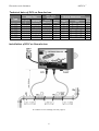
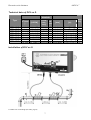
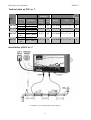
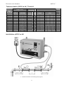
ANTICA++
Electronic scale eliminator
Application of AntiCa++ devices
AntiCa++ devices are intended to protect:
• Boilers and heat generators
• Home appliances and domestic hot water heaters, including gas-fired instant hot water
systems, eliminating expensive maintenance of heating elements
• Heat exchangers, converters, water distribution systems, heating district distribution
systems, generation of hot water, hydronic systems
• Process equipment and systems in which the formation of scale takes place as a result of
temperature or pressure changes in hard water.
AntiCa++ Performances
The high performance of AntiCa++ devices in hard water applications is because they are
designed, manufactured and installed in consideration of the following parameters:
• chemical composition of the treated water
• the pipe diameter where the device is being installed
• volume of water or water velocity flow through the pipe where the device is being installed
• pipe material where the device is being installed – metal or plastic
Description of AntiCa++ devices
AntiCa++ devices consist of:
• electronic unit
• power coil cable (red)
• circuit for control level based on flow signal from flow meter ( EUV xx AI )
• circuit for level switching through timer ( EUV xx T a TI )
• circuits for manual switching based on flow ( EUV xx MI )
• circuits signals of device functions
Signalling
a) optic signals:
• power ON – red LED diode marked "POWER"
• power to coil cable (red) - green LED diode marked "DESCALING"
• control based on water volume flow EUV xx AI
• scale change control EUV xx T, a TI
Note.:
Types EUV 15 Dom to EUV 25 Dom have only visual green LED diode signal marked
“DESCALING”
b) acoustic signal – type EUV xx MI, TI a AI
• power disconnection – audio ringing
c) contact signal – EUV xx MI, TI a AI
dry open contact on terminal strip for remote signalling or lock out in the event of lost signal of
the output circuit
AntiCa++ location and installation
Install AntiCa++ device upstream of the process device that needs to be protected against
scale formation.
Install the device downstream of open-to-atmosphere water reservoir or tank. The installation
upstream of the water reservoir or tank open to atmosphere is not recommended. The
treated water open to atmosphere even for a short period of time loses the benefit of
2
ANTICA++
Electronic scale eliminator
treatment and is rendered useless. However the installation of the device in open water
circuits downstream of the reservoir or holding tank is beneficial.
In closed water circuits the installation of the device upstream of the holding tank is highly
recommended. When the device is installed upstream of the holding tank, then the tank doubles
as a sedimentation vessel where the scale separates from the water. The sediments can then be
flushed out of the system. However, if thus treated water is not used within 48 hours the
treated water reverts to the raw supplied water state and needs to pass again through AntiCa++
device to protect the system.
If in doubt of the device placement in the systems consult with the manufacturer or his
representative.
Basic requirements:
Before installing the device on the designated pipe, determine the hardness of the raw water
in pH. Where possible determine the amount of iron (Fe) in the raw water. From the water
hardness analysis consult Table 1 below and install the number of coil windings indicated. If the
water hardness is greater than 40°dH, then it is necessary to order a special device.
For devices EUV xx Dom, D and T wind the number of coil windings as indicated in Table 1
Total water
<16
16 - 24 24 - 32 32 - 40
> 40
hardness °dH
Number of coil
11
12
13
14
15
windings (2x)
In case the water hardness cannot be determined then it is recommended to install 2 x14 coil
windings.
For devices EUV xx MI, TI and AI wind 2x11 coil windings with the separation distance
between coils shown in Table 2 below in metric
DN of piping [mm]
50 - 65 80 - 100 125 - 150 200 - 250 300 - 500
Distance L [mm]
200
250
300
500
800
For devices EUV xx MI, TI and AI wind 2x11 coils windings with the separation distance
between coils shown in Table 2 below in imperial units
DIA of piping [in]
2 – 2 1/2
3-4
5-6
8 - 10
12 - 20
Distance L [in]
8
10
12
20
32
For devices EUV xx MI and TI set up the strength of signal:
• in accordance with the table printed on the side panel of the device for water hardness up
to 20°dH
• one step up for water hardness between 20 - 30°dH ( eg. from 7 to 8 )
• two steps up for water hardness between 30 - 40°dH ( eg. from 6 to 8 )
• for water hardness above 40°dH it is necessary to consult on the settings with the
manufacturer or his representative and/or order a special device
Note:
• When the water analysis reveals that the iron (Fe) content is Fe>1 mg/l and pH <6.5 or >8.3
it is necessary to consult on the device settings with the manufacturer or his representative.
Installation:
1. Fasten the device to the wall with the supplied screws at a distance of 1,5 m max from the
installed coils on the pipe that is intended for protection.
• For devices EUV xx MI, TI and AI screw in the plastic hanging eyes supplied.
• For devices EUV xx T and TI install and connect the timer (when timer is part of the supply).
3
ANTICA++
Electronic scale eliminator
• For devices EUV xx AI connect to water volume measuring device.
2. From supplied power cable (red), wind on vertical or horizontal straight pipe 2 coils with the
number of turns indicated in Table 1 and the distance between them indicated in Table 2.
Please note that both windings must run in the same direction as shown on the installation
diagrams for each type of the device.
• Secure the start and finish of each coil winding with the supplied wire ties to the pipe so
the remaining length of both ends of the remaining power cable (red) are approximately of
the same length.
CAUTION!
Wind coils in numbers and direction shown on page 4, Table 1, with the correct distance
between coils, Table 2, on a straight pipe following the distances from fixtures or tees shown on
Device installation. Follow the recommendation of minimum distance to pipe fittings or tees
from the end of the coils that need to be greater or equal to 3 x OD of the pipe where the coils
are installed. Pay attention to the fact that the minimum distance to other parallel piping
should be 2 x OD minimum.
3. After installing the desired numbers of windings at the correct distance between them,
wound in the same direction, secured with cable ties to the pipe, connect the power cable
(red), to the plugs on the Device. There is no preference as to the polarization, hence it is
not designated which end is plugged into the device’s connectors. However pay attention to
piping material, “Metal” or “Plastic” on devices EUV DOM, D, T as the proper function of the
device is dependent on the type of pipe material on which the coils are installed.
4. Plug the device into an electrical wall outlet. All control LEAD lights on the device will lightup.
5. Program the timers as indicated in the manual for devices EUV xx T and TI.
6. For EUV xx MI and TI program the water meter in accordance with the side panel of the
device.
7. Change the setting to position „A“ for EUV xx AI device.
Checking the function of AntiCa ++ device
Considering the fact that AntiCa++ devices change only the physical properties of the treated
water (formation of aragonite crystals), the functioning of the device can be determined
indirectly. If the water hardness upstream and downstream of the installed AntiCa++ device is
the same as it is downstream of the protected equipment (hot-water heater, exchanger, etc.),
no scaling of the equipment takes place.
When the device is installed on older systems that were not protected and scaling has already
taken place, then during system de-scaling the hardness of exiting water may be higher than the
initial hardness of water entering the system, indicating de-scaling is taking place. It is possible
to estimate the intensity of system de-scaling from the difference in hardness of systems outlet
and outlet of AntiCa++ device. It is possible to regulate the rate of the system cleaning process
by changing the level of the AntiCa++ device output signal.
If the water hardness exiting the system is lower than that measured after the AntiCa++ device,
sedimentation in the system has occurred and cleaning of the system must be scheduled.
In cases where the AntiCa++ device is installed on an electric hot water boiler that was not
protected before and has been in use for some time, the boiler must be de-scaled before the
AntiCa++ device is installed. If de-scaling is not done before installing the device the softened
scale may fall down from the boiler’s wall and damage the heating elements.
Operation and maintenance of AntiCa++ devices.
The devices do not require any special operation or maintenance. Operations consist of
routine checking of LED lights, which indicate the functioning of the device. If one of the
LED lights is OFF, it may indicate power failure or that the device is not plugged in or that the
device is faulty. In the case of a faulty device contact the manufacturer or his representative.
4
ANTICA++
Electronic scale eliminator
Considerable effort should be made to monitor the system where the AntiCa++ device is
installed. On older systems where scaling took place before the AntiCa++ device installation, the
treated water softens the scaling and in time may restore the system to its original state.
Depending on the severity of system scaling, the loose scale in piping systems with reduced flow
velocity can settle in any place and invoke system blockage. Therefore flushing of the system
must take place. Install dirt pockets with valves to drains in piping if this was not done in the
original installation.
Closed systems with low pressure and low flow should be flushed regularly till the sediments are
not visible in flushed water. Aragonite crystals could in this environment produce sediment like
powder dissolved in water, thus flushing of the system must take place to remove them.
5
ANTICA++
Electronic scale eliminator
Technical data of EUV xx Dom devices.
Water Flow
Type
EUV 15
EUV 20
EUV 25
EUV 32
EUV 40
EUV 50
EUV 65
Dom
Dom
Dom
Dom
Dom
Dom
Dom
3
[m /hour
]
0.1
0.2
0.3
0.4
0.8
1.2
2.0
–
-
0.3
0.6
0.9
1.4
2.3
3.5
6.0
[USGPM]
1.6 – 4.75
3.17-9.51
4.75-14.26
6.34-22.19
12.68-36.45
19-55.47
31.7-95.1
Max. Pipe
diameter
inside outside
[mm-inch] [mm]
15 (1/2")
20 (3/4")
25 (1")
32 (5/4")
40 (6/4")
50 (2")
65 (2 1/2")
21
27
34
42
48
60
76
Device dimensions
[mm]
110x70x55
110x70x55
110x70x55
160x96x67
160x96x67
160x96x67
160x96x67
Installation of EUV xx Dom devices.
N –numbers of coil windings (see tab. page.4)
6
[in]
43/8 x 23/4 x 2
43/8 x 23/4 x 2
43/8 x 23/4 x 2
65/16 x 33/4 x 25/8
65/16 x 33/4 x 25/8
65/16 x 33/4 x 25/8
65/16 x 33/4 x 25/8
Input
[VA]
2
2
2
5
5
5
5
ANTICA++
Electronic scale eliminator
Technical data of EUV xx D.
Water Flow
Type
EUV
EUV
EUV
EUV
EUV
EUV
EUV
EUV
10
15
20
25
32
40
50
65
3
D
D
D
D
D
D
D
D
[m /hour
]
[USGPM]
0.1 - 0.45
0.3 - 1
0.6 - 1.8
0.9 - 2.7
1.4 - 4.4
2.3 - 6.8
3.5 -10.5
6.0 -18.0
1.6 - 4.75
4.75 -15.85
9.51-28.53
14.26-42.79
22.19-69.74
36.45-107.78
55.47-166.42
95.1-285.3
Max. pipe
diameter
outs
inside
ide
[mm[mm
inch]
]
10 (3/8")
15 (1/2")
20 (3/4")
25 (1")
32 (5/4")
40 (6/4")
50 (2")
65 (2 1/2")
Installation of EUV xx D.
N –numbers of coil windings (see table, page 4)
7
17
21
27
34
42
48
60
76
Device dimensions
[mm]
160x96x67
160x96x67
160x96x67
160x96x67
160x96x67
160x96x67
160x96x67
215x130x82
Input
[VA]
[in]
65/16 x
65/16 x
65/16 x
65/16 x
65/16 x
65/16 x
65/16 x
87/16 x
33/4 x
33/4 x
33/4 x
33/4 x
33/4 x
33/4 x
33/4 x
51/8 x
25/8
25/8
25/8
25/8
25/8
25/8
25/8
31/4
5
5
5
5
5
5
5
6
ANTICA++
Electronic scale eliminator
Techical data of EUV xx T.
Water flow
Type
[m3/hour
]
I. 0,.4 -1.4
II. 1.4 -4.4
I. 0.8 –2.3
EUV 40 T
II. 2.3 -6.8
I. 1.2 –3.5
EUV 50 T II. 3.5 10.5
I. 2.2 – 6.0
EUV 32 T
EUV 65 T II. 6.0 18
[USGAL]
15.85 - 22.19
22.19 - 69.74
12.68 – 36.45
36.45 -107.78
19 – 55.47
55.47 -166.42
Max. pipe
diameter
Internal
Ext.
[mm[mm]
inch]
Device dimensions
[mm]
[in]
Input
[VA]
32 (5/4")
42
215x130x82 87/16 x 51/8 x 31/4
6
40 (6/4")
48
215x130x82 87/16 x 51/8 x 31/4
6
50 (2")
60
215x130x82 87/16 x 51/8 x 31/4
6
65 (2 1/2")
76
215x130x82 87/16 x 51/8 x 31/4
6
34.87 -95.1
95.1 – 285.3
Installation of EUV xx T.
N –numbers of coil windings (see table, page 4)
8
ANTICA++
Electronic scale eliminator
Technical dada of EUV xx MI, TI and AI.
Water Flow
Type
MI, TI, AI
3
[m /hr]
EUV 50
0.2–11
EUV 65
0.3–18
EUV 80
0.5–27
EUV 100
0.8–42
EUV 125
1.4–66
EUV 150 2.0-100
EUV 200 3.2-170
EUV 250 6.0-270
EUV 300 8.0-380
EUV 400 1.0-680
EUV 500 2.0-1100
[USGPM]
3.17 -174.35
4.75 -285.3
7.92 -427.95
12.68 – 665.7
22.19 -1046.1
31.7 -1585
50.72 -2694.5
95.1 -4279.5
126.8 -6023
15.85 -10778
31.7 -17435
Max. pipe
diameter
Internal Ext.
[mm- [mm
inch]
]
50 (2") 60
65 (21/2") 76
80 (3") 89
100 (4") 115
125 (5") 140
150 (6") 166
200 (8") 219
250 (10") 273
300 (12“) 324
400 (16“) 430
500 (20“) 535
Device dimensions
[mm]
275x220x140 107/8 x 85/8 x 51/2
275x220x140 107/8 x 85/8 x 51/2
275x220x140 107/8 x 85/8 x 51/2
275x220x140 107/8 x 85/8 x 51/2
275x220x140 107/8 x 85/8 x 51/2
275x220x140 107/8 x 85/8 x 51/2
275x220x140 107/8 x 85/8 x 51/2
275x220x140 107/8 x 85/8 x 51/2
275x220x140 107/8 x 85/8 x 51/2
370x275x140 145/8 x 107/8 x 51/2
370x275x140 145/8 x 107/8 x 51/
Installation of EUV xx MI.
L – distance between coil windings (see page 4)
9
[in]
Input
[VA]
8
8
8
8
10
10
10
10
10
16
16
ANTICA++
Electronic scale eliminator
Installation of EUV xx TI.
L – distance between coil windings ( see. page.4)
Installation of EUV xx AI.
L – distance between coil windings (see. page.4)
10
ANTICA++
Electronic scale eliminator
Timer TM-6331
(Daily and weekly programming).
Button functions:
CLOCK Indication and time setting
DAY
Day setting
HOUR Clock setting
MIN
Minutes setting
TIMER Selection of individual time duration On/Off
MANUAL Manual operation On/Off
R
Accepts all settings and starts the program
Installation:
Take out the screw located on front panel in right corner. The plate
with terminals is located there. Affix the plate and connect wires in
accordance with schematic. Close the cover and connect to power.
Press button “R” to start the device.
Warning:
• The installation must conform to the local electrical code.
• Timer can be used to switch safety voltage in accordance with
STN 341010
Timer setting.
Day setting.
When setting time/day depress and hold the CLOCK button and
subsequent pushing of the buttons DAY (HOUR, MIN) sets the day of the day of the week, (hour
and min).
Setting the timers On/Off (times setting).
1. Press the TIMER button that starts the program of the first timer.
2. Pres the DAY button to set the week day when the timer starts ON.
It is possible to set:
• Each day individually
• All working days
• Saturday and Sunday only
• All days... 15 variations altogether.
3. With button HOUR the starting hour is set.
4. MIN button sets the starting minute.
5. Button TIMER is programmed OFF time of the first timer.
6. Repeating the above instruction #2 to #5 set all the desired On/Off times.
7. Second time pressing the TIMER button provides for checking of the program.
8. The programming can be interrupted or finished by pressing the CLOCK button.
9. The timer operates the program only when the timer is set to AUTO. By pressing the AUTO
button a second time, the timer switches to ON or OFF display.
11
ANTICA++
Electronic scale eliminator
Specifications of timers model TM 6331.
Power
Max. current
Back-up
120VACV ,50 – 60 Hz
16 A / 250 V alternate. Cosφ=1
20 A / 125 V alternate. Cosφ=1
Battery CR2032
Ambient temperatures -10 to + 50°C non-corrosive atmosphere
Number of contacts
Programming
Accuracy
Time
16 (8 NO and 8 NC)
8 timers with 15 modes
± 0,5 sec. / 24 hours
Better than 1 sec
12
ANTICA++
Electronic scale eliminator
Technical data for digital Volume measurement devices EUV xx AI.
(OPTO OD 01, OD 02.)
Sensor
Specification
Constant
IR – reflection ray in accordance with DIN
19234
8,2 V DC ( z EUV xx
Feeder voltage
AI )
Reflection currant
< 1 ,2 mA
Current without
reflection
> 2,1 mA
DN 40 - 125
1 impulse / litre
DN 150 - 300
1 impulse / 10 litres
Connecting digital volume counting sensor:
1. Connect middle wire (opto+) shield cable to terminal #4.
2. Shielding (opto-) connect to terminal #1.
When connecting EUV xx AI to non- metal pipe jump terminals #2 and #3.
When connecting EUV xx AI to metal pipe do not jumper terminals #2 and 3 (leave them
free).
Technical data of current sensors.
When ordering current sensor 0-20 mA or 4-20 mA, specify the characteristic of receiver
(graph or table). If the characteristic of the receiver is linear, it is adequate to specify
the starting and finishing point ( eg. 0 mA=0 m3 . 20 mA=15 m3 ).
Installation of current sensor:
1. Middle wire („ + I „) of shading cable connect to terminal #.4
2. Shading ( „– I „) connect to terminal #1.
When connecting EUV xx AI to non-metal pipe jump terminal#2 and #3.
When connecting EUV xx AI to metal pipe do not jumper terminals #2 and #3 (leave
them free)
13
ANTICA++
Electronic scale eliminator
Technical data of AntiCa++ devices
Power
Room temperature
Pipe surface temperature
EUV xx Dom
Other types
Length of power coil cable
(red)
Length of power cord
EUV xx Dom
Other types
Weight EUV
EUV 15 - 25 Dom
EUV 32 - 65 Dom
EUV 15 - 80 D
EUV 32 – 65 T
EUV xx MI, TI AI
Input EUV
EUV 15 - 50 Dom
EUV 65 - 65 Dom
EUV 10 – 50 D
EUV 65 - 80 D
EUV 32 T – 65 T
EUV 50 – 100 MI, TI, AI
EUV 125 – 300 MI, TI, AI
EUV 400 – 500 MI, TI, AI
Contact signal functions
Load on contact relay:
Max voltage at terminals:
Pulsation current sensor
transmitter
Input voltage
Reflection power
Power without refection
Constant DN 50 – DN 125
Constant DN 150 – DN 300
Constant DN 300 – DN 500
Digital volume counting
sensor
Current without flow
Current at max. flow
120 VACV, 50-60 Hz
+1 to + 50°C
max. 70 °C
max.150 °C
max 1,5 m
max 1,5 m
max 2,2 m
0,5 kg
1 kg
2,5kg
from 5 kg and above
2 – 16 VA depending on type
of device
2 VA
5 VA
6 VA
8 VA
10 VA
16 VA
15 W (ohm load, max 1A)
125 V
8,2 V DC ( z EUV xx AI )
< 1 ,2 mA
> 2,1 mA
1 impulse / litre
1 impulse / 10 litres
1 impulse / 100 litres
Specify sensor’s characteristic
0 mA ( 4 mA )
20 mA
14


![User`s Manual MV2000[SU:M] Ventilator System 0470](http://vs1.manualzilla.com/store/data/005841388_1-c867b5a0773523e6306e353a41d4c56d-150x150.png)