1
Universal Keyboard Wedge
Programming Guide
PSC Inc
959 Terry Street
Eugene, Oregon 97402
Telephone: (541) 683-5700
Fax: (541) 345-7140
An Unpublished Work - All rights reserved. No part of the
contents of this documentation or the procedures described
therein may be reproduced or transmitted in any form or by
any means without prior written permission of PSC Inc. or its
wholly owned subsidiaries (“PSC”). Owners of PSC products
are hereby granted a non-exclusive, revocable license to
reproduce and transmit this documentation for the
purchaser’s own internal business purposes. Purchaser shall
not remove or alter any proprietary notices, including
copyright notices, contained in this documentation and shall
ensure that all notices appear on any reproductions of the
documentation.
Should future revisions of this manual be published, you can
acquire printed versions by contacting PSC Customer
Administration. Electronic versions may either be
downloadable from the PSC web site (www.psc.com) or
provided on appropriate media. If you visit our web site and
would like to make comments or suggestions about this or
other PSC publications, please let us know via the “Contact
PSC” page.
Disclaimer
Reasonable measures have been taken to ensure that the
information included in this manual is complete and accurate.
However, PSC reserves the right to change any specification
at any time without prior notice.
PSC is a registered trademark of PSC Inc. The PSC logo is a
trademark of PSC. All other trademarks and trade names
referred to herein are property of their respective owners.
Table of Contents
Introduction ------------------------------------------------- 1
Manual Overview ........................................... 1
Manual Contents ............................................ 3
How to Use this Manual ................................. 6
How to Program Your Scanner ....................... 8
If You Make a Mistake... ............................... 11
Return to Factory Settings ........................... 12
Programming Manual References ................ 13
Communication Modes -------------------------------- 14
Keyboard Wedge Mode ............................... 15
Cloning Mode ............................................... 17
PC Down/UpLoad Mode .............................. 20
Universal Keyboard Wedge I/f Configuration ---- 23
Activating the Universal Keyboard Wedge
Interface ....................................................... 25
Terminal/Keyboard Settings ......................... 27
Terminal/Keyboard Number Pad .................. 28
End of Message Characters ......................... 33
Upper/Lower Case Options .......................... 38
Types of Numeric Characters ....................... 39
Intercharacter Delay ..................................... 41
WYSE Timeout ............................................. 44
Editing Mode --------------------------------------------- 46
R44-2021
i
Programming Sequence .............................. 49
PHASE A ..................................................... 55
PHASE B1 ................................................... 57
PHASE B2 ................................................... 67
PHASE B3 ................................................... 69
PHASE B4 ................................................... 71
PHASE C0 ................................................... 75
PHASE C1 ................................................... 79
PHASE C2 ................................................. 109
PHASE C3 ................................................. 113
PHASE D ................................................... 120
PHASE E ................................................... 121
Activate editing mode ................................. 121
Match Not Performed ................................. 126
RS-232 -------------------------------------------------- 127
RS-232 Interface Configuration .................. 127
RS-232 Restrictions ................................... 130
RS-232 Activation ...................................... 131
RS-232: Baud Rate ................................... 132
RS-232: Parity ........................................... 136
RS-232: Data Bits ..................................... 138
RS-232: Stop Bits ..................................... 139
RS-232: End of Message Characters ........ 140
RS-232: Intercharacter Delay .................... 144
RS-232: ACK/NAK Protocol ...................... 147
ii
Universal Keyboard Wedge Programming Guide
RS-232: Xon/Xoff Protocol ........................ 148
RS-232: RTS/CTS Protocol ...................... 149
Double RS-232 PC Term Mode – Activate . 150
RS-232 In/Out Mode – Activate .................. 152
RS-232: Full ASCII Emulation ................... 153
Wand Emulation Interface Configuration -------- 154
Wand Emulation I/F Configuration .............. 155
Wand Emulation Activation ......................... 156
Wand Emulation:
Transmission Speed .................................. 157
Wand Emulation: Bar/Space Polarity ......... 159
Wand Emulation: Idle State ....................... 160
Symbologies ------------------------------------------- 161
Symbology Selection .................................. 162
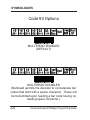
Code 39 Options ........................................ 170
Label Code 4/5 Options .............................. 185
Interleaved 2 of 5 Options .......................... 186
UPC/EAN Options ...................................... 197
Codabar Options ........................................ 217
Code 128 Options ...................................... 220
UCC/EAN 128 Options ............................... 223
Standard 2 of 5 Options ............................. 224
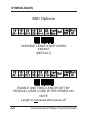
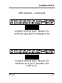
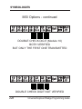
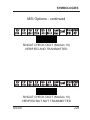
MSI Options ............................................... 226
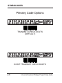
Plessey Code Options ................................ 230
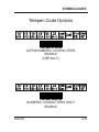
Telepen Code Options ................................ 231
R44-2021
iii
Code 93 Options ........................................ 232
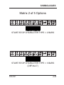
Matrix 2 of 5 Options .................................. 233
BC412 Options ........................................... 241
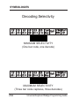
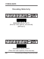
Decoding Selectivity ................................... 242
Symbology Leading Identifiers ................... 243
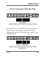
Three Character AIM Identifier ................... 245
Decoding Selectivity ................................... 246
Appendix A
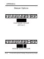
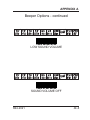
Beeper Options .......................................... A-1
Preamble/Postamble .................................. A-5
Data Output Transmission .......................... A-8
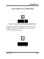
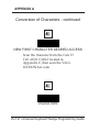
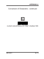
Conversion of Characters .......................... A-9
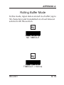
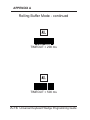
Rolling Buffer Mode .................................. A-15
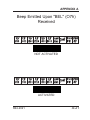
Beep Upon "BEL" (O7h) Received ........... A-21
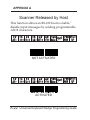
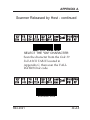
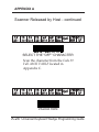
Scanner Released by Host ...................... A-22
Transmission of the Full ASCII ................. A-25
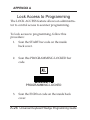
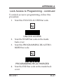
Locking access to programming ............... A-26
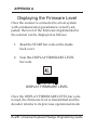
Displaying the firmware level .................... A-29
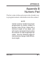
Appendix B Number Pad ---------------------------- B-1
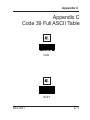
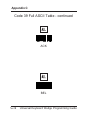
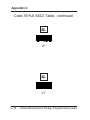
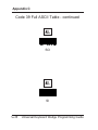
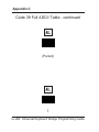
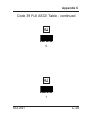
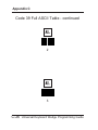
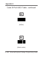
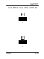
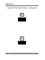
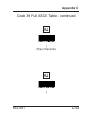
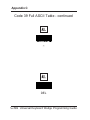
Appendix C Code 39 Full ASCII Table ----------- C-1
Appendix D Code 39 ASCII Extended Table --- D-1
Appendix E Multiread Character Table ---------- E-1
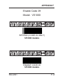
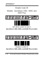
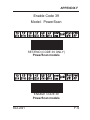
Appendix F Enabling Code 39 --------------------- F-1
iv
Universal Keyboard Wedge Programming Guide
INTRODUCTION
Introduction
Manual Overview
This manual contains programmable features and
information for the Universal Keyboard Wedge
interface ONLY.
NOTE
The Universal Keyboard Wedge interface offers a larger, more enhanced feature set than the standard Keyboard Wedge interface covered by the other programming
manuals for your scanner. Make
sure that you select the correct interface type (standard Keyboard
Wedge or Universal Keyboard
Wedge) that offers the options you
require for your installation, and that
you have the correct manual(s) that
will allow you to program all the
desired features.
R44-2021
1
INTRODUCTION
Manual Overview - continued
You will need to reference the programming guide
that is specific to your scanner model in order to
access and modify features other than those specific
to the Universal Wedge interface. See the topic,
Programming Manual References, later in this section
for important information on other manuals you
may need to use.
As previously stated, this manual contains programming and feature information for scanners
equipped with PSC® Universal Keyboard Wedge
interface capabilities. At the time of this writing,
scanner models that offer this interface are:
HS1250
QuickScan®VS800
VS1000
VS1200
SP400
PowerScan®
QuickScan® QS1000
QuickScan® Duet®
QuickScan® QS6000/QS6000 Plus
2
Universal Keyboard Wedge Programming Guide
INTRODUCTION
Manual Overview - continued
Other scanners could also have the ability to use
these features. Call your PSC dealer to verify if
your scanner can take advantage of Universal
Wedge features.
Manual Contents
These sections are included in this manual:
• Introduction - If you've never programmed
a scanner before, you'll want to familiarize
yourself with the basics included in this
section.
• Communication Modes - This section
includes information about physical
connections and cabling, using Cloning
Mode to duplicate programming configuration between scanners, and also how to use a
PC to down/upload software to a scanner.
R44-2021
3
INTRODUCTION
Manual Contents - continued
• Editing Mode - The Universal Keyboard
Wedge interface also supports the
scanner's ability to edit bar code label data
before sending it to the host terminal. This
feature allows the flexibility of character
matching, defining fields, the addition of
preambles/postambles, and more.
• Wedge Programming - This section
contains programming specific to keyboard wedge features, such as return to
factory defaults, selecting the specific
keyboard type, "end of message" characters, numeric characters, time out between
characters, and WYSE time out.
• RS-232 Interface Configuration - The
RS-232 interface features provided in this
section are an enhanced set that are only
available for scanners equipped with the
Universal Keyboard Wedge interface.
These features include options for baud rate,
parity, stop bits, "end of message" characters,
4
Universal Keyboard Wedge Programming Guide
INTRODUCTION
Manual Contents - continued
intercharacter delay, ACK/NAK protocol,
Xon/Xoff protocol, double RS-232 mode, and
RS-232 in/out mode.
• Wand Emulation I/F Configuration - Like
the RS-232 interface, the Wand Emulation
interface features contained in this manual
are a special programming set offering
different options than the standard PSC
Wand Emulation feature set.
• Symbologies - This section allows you to
select and customize settings from among
several bar code symbologies that are in
common use today.
• Appendices - The appendices to this
manual contain general feature settings
that are common to all interfaces, such as
beeper, preamble/postamble, locking
access to programming, displaying the
firmware level, etc. The appendices also
provide handy numeric keypads, character
tables, as well as the full ASCII table.
R44-2021
5
INTRODUCTION
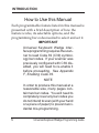
How to Use this Manual
Each programmable feature listed in this manual is
presented with a brief description of how the
feature works, its selectable options, and the
programming bar codes needed to select and set it.
IMPORTANT
Universal Keyboard Wedge interface programming requires the scanner to read Code 39 (C39) symbology bar codes. If your scanner was
previously configured with C39 disabled, you will need to re-enable it
before proceeding. See Appendix
F, Enabling Code 39.
NOTE
In order to produce this manual at a
reasonable size, many pages contain two bar codes. You will need to
completely cover any bar codes you
do not intend to scan (with your hand
or a piece of paper) to prevent accidental mis-programming.
6
Universal Keyboard Wedge Programming Guide
INTRODUCTION
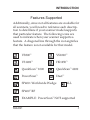
Features Supported
Additionally, since not all features are available for
all scanners, you'll need to reference each description to determine if your scanner model supports
that particular feature. The following icons are
used to indicate when your scanner supports a
feature. A diagonal line through the icon signifies
that the feature is not available for that model.
VS800™
VS1000™
VS1200™
HS1250™
QuickScan™ 1000
QuickScan™ 6000
PowerScan™
Duet™
SP400™ Worldwide Wedge
ALL
SP400™ RF
EXAMPLE: PowerScan™ NOT supported
R44-2021
7
INTRODUCTION
How to Program Your Scanner
To program your scanner using this manual,
follow these guidelines:
1. Entering Programming Mode is done by
scanning the START bar code located on
the inside back cover of this manual.
NOTE
The scanner indicates when it is in
Programming Mode by continuously
flashing its green LED indicator lamp.
The scanner must be in Programming
Mode in order to modify any programmable features.
8
Universal Keyboard Wedge Programming Guide
INTRODUCTION
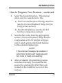
How to Program Your Scanner - continued
2.
3.
4.
Select the desired interface. This manual
offers only two selections for this:
a) The Universal Keyboard Wedge interface
(see the Universal Keyboard Wedge Interface
Configuration section).
b) The RS-232 interface (see the RS-232
Interface Configuration section).
Scan the bar codes from the appropriate
section (Universal Keyboard Wedge Interface
Configuration or RS-232 Interface Configuration) to select options and modify features
for the selected interface type.
NOTE
If the scanner's beeper is enabled, it
will emit a "good read" beep as each
bar code is read successfully.
After all desired programming parameters have been set, you must end the
session by scanning the END bar code
located on the inside back cover of this
manual.
R44-2021
9
INTRODUCTION
How to Program Your Scanner - continued
NOTE
Upon scanning the END bar code,
the scanner's green LED will then
cease its continuous flashing, indicating it is no longer in Programming
Mode. The scanner is now ready for
normal operation.
5.
10
If you will require the scanner to perform
label editing, turn to the Editing Mode
section and carefully follow the instructions to program this function.
Universal Keyboard Wedge Programming Guide
INTRODUCTION
If You Make a Mistake...
If, during a programming session, you find that you
are unsure of the scanner's Universal Keyboard
Wedge settings or wish to re-set this configuration,
use the Return to Factory Settings bar code on the
next page to return all Universal Wedge parameters
to their factory settings. Scanning this bar code will
also reset any Universal Wedge changes made
during previous programming sessions.
NOTE
When your scanner is first connected
to a keyboard wedge host, the factory
default setting (unless your scanner
was custom configured) is communication with a U.S. PC/AT keyboard.
CAUTION
Use the FACTORY DEFAULTS bar
code with caution, since it will disable/reset ALL Universal Wedge features that may have been programmed since the scanner's installation.
R44-2021
11
INTRODUCTION
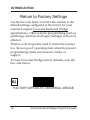
Return to Factory Settings
Use the bar code below to return the scanner to the
default settings configured at the factory for your
scanner's original Universal Keyboard Wedge
specifications. Other scanner programming (such as
symbology selection and beeper settings) will not be
affected.
This bar code is typically used to return the scanner
to a "known good" operating state when the present
programming status is not known, faulty, or
suspect.
To reset Universal Wedge factory defaults, scan the
bar code below.
FACTORY DEFAULTS, UNIVERSAL WEDGE
12
Universal Keyboard Wedge Programming Guide
INTRODUCTION
Programming Manual References
In order to properly configure all scanner programming features for your particular application, you
may need to use other additional programming
manuals available from PSC®. Here are manuals
that are currently available:
R44-1020 SP400™ Programming Guide
R44-2039 Keyboard Wedge Connectivity Guide
R44-1140 SP*ACE™ and VS1000™ Prog. Guide
R44-1340 VS1200™/HS1250™ Programming
Guide
R44-1540 QuickScan™ 6000/6000 Plus
Programming Guide
R44-1740 Duet™ Programming Guide
R44-1840 PowerScan™ Programming Guide
R44-2018 QuickScan™ 1000 Programming Guide
Call your PSC dealer to inquire about other programming manuals that are available, or you can
find copies of programming manuals and more
information on the internet at www.pscnet.com.
R44-2021
13
COMMUNICATION MODES
Communication Modes
The Universal Keyboard Wedge interface offers
several alternate modes to allow flexibility in
communication between the scanner, its host, and
even with other scanners.
These modes are:
• Keyboard Wedge Mode -- is the standard
operational/communication mode.
• Cloning Mode -- allows duplication of
configuration between a source scanner
and a target scanner.
• PC Down/Upload Mode -- permits
downloading of parameter values from a
PC to a scanner. Additionally, it enables a
scanner's configuration information to be
displayed and saved on a PC. Finally, it
allows testing of the scanner's RS-232
transmissions to the PC.
• Editing Mode -- provides a sophisticated
capability to edit input data before its
transmission to the host terminal. See the
following section for more information.
14
Universal Keyboard Wedge Programming Guide
COMMUNICATION MODES
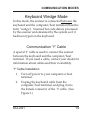
Keyboard Wedge Mode
In this mode, the scanner is connected between the
keyboard and the computer/host terminal (thus the
term "wedge"). Scanned bar code data is processed
by the scanner and emulated by the system as if it
had been typed on the keyboard.
Communication 'Y' Cable
A special 'Y' cable is used to connect the scanner
between the keyboard and the computer/host
terminal. If you need a cable, contact your dealer for
information about cables and their availability.
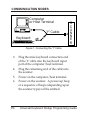
'Y' Cable Installation
1. Turn off power to your computer or host
terminal.
2. Unplug the keyboard cable from the
computer/host terminal, and plug it into
the female connector of the 'Y' cable. (See
Figure 1.)
R44-2021
15
COMMUNICATION MODES
Computer
or Host Terminal
'Y' Cable
Keyboard
S
C
A
N
N
E
R
Figure 1. Connecting the 'Y' Cable
3.
4.
5.
6.
16
Plug the male keyboard connection end
of the 'Y' cable into the keyboard input
port of the computer/host terminal.
Plug the remaining end of the cable into
the scanner.
Power on the computer/host terminal.
Power on the scanner. A power-up beep
or a sequence of beeps (depending upon
the scanner type) will be emitted.
Universal Keyboard Wedge Programming Guide
COMMUNICATION MODES
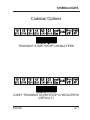
Cloning Mode
When a quantity of scanners must all be programmed with identical parameter settings,
Cloning Mode permits quick and easy duplication
of those settings from a pre-programmed source
scanner to a target scanner.
To use Cloning Mode, follow these instructions:
1. Program a source scanner with all the
settings necessary to allow full functionality with your system. Test this source
scanner carefully to ensure that all
parameters are correctly set.
2. Connect the source scanner to a target
scanner using an approved cloning cable
for your scanner type. If you need more
information or need to obtain cables,
contact your dealer.
3. Connect the source scanner and the target
scanner to power.
4. Power-on both scanners.
R44-2021
17
COMMUNICATION MODES
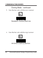
Cloning Mode - continued
5.
Scan this bar code with the source scanner:
TRANSMIT CONFIGURATION
6.
Scan this bar code with the target scanner:
RECEIVE CONFIGURATION
18
Universal Keyboard Wedge Programming Guide
COMMUNICATION MODES
Cloning Mode - continued
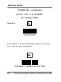
7.
Power-off the target scanner, and connect
the next target scanner. Repeat steps 2
through 6.
NOTE
When cloning multiple scanners, it is
not necessary to read the TRANSMIT CONFIGURATION bar code
(step 5) each time a different target
scanner is connected. Simply scan
the RECEIVE CONFIGURATION
bar code in step 6 as each target
scanner is connected for cloning.
To exit Cloning Mode, power the source scanner
off, then on.
R44-2021
19
COMMUNICATION MODES
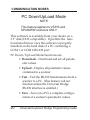
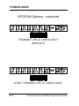
PC Down/UpLoad Mode
NOTE
This feature applies to VS/HS and
SP400WW scanners ONLY.
This software is available from your dealer on a
3.5" disk (DOS compatible). It permits the functions listed below once the software is properly
installed on the hard disk of a PC containing a
COM 1 or COM 2 RS-232 port.
PC Down/UpLoad Mode functions are:
• Download – Download and set all parameter values.
• Upload – Display all parameter values
contained in a scanner.
• Test – Test the RS-232 transmissions from a
scanner to a PC. (This feature will not
function unless the Universal Wedge
RS-232 interface is enabled.)
• Save – Save (on a PC) a complete configuration of a scanner's parameter values.
20
Universal Keyboard Wedge Programming Guide
COMMUNICATION MODES
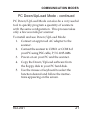
PC Down/UpLoad Mode - continued
PC Down/UpLoad Mode can also be a very useful
tool to quickly program a quantity of scanners
with the same configuration. This process takes
only a few seconds per scanner.
To install and use Down/UpLoad Mode:
1. Connect an approved AC adapter to the
scanner.
2. Connect the scanner to COM 1 or COM 2 of
your PC using PSC cable, P/N: 6015-0486.
3. Power-on on your PC and the scanner.
4. Copy the Down/UpLoad software from
the floppy disk to your PC hard disk.
5. Use the mouse or keyboard to select the
function desired and follow the instructions appearing on the screen.
R44-2021
21
COMMUNICATION MODES
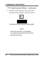
PC Down/UpLoad Mode - continued
6.
Read the following bar code to start the
transfer between the PC and the scanner.
DOWN/UPLOAD DIALOG RELEASE
NOTE
When the transfer is completed,
the scanner will return to its normal
operational mode.
22
Universal Keyboard Wedge Programming Guide
Universal KBW Interface Configuration
Universal Keyboard Wedge
Interface Configuration
This section provides instructions and bar codes
for programming Universal Keyboard Wedge
parameters.
Programmable options included in this section are:
• Terminal/Keyboard Interface Selection
• End of Message Characters
• Upper/Lower Case Options
• Types of Numeric Characters
• Intercharacter Delay
• WYSE Timeout
R44-2021
23
Universal KBW Interface Configuration
Programming
Universal Keyboard Wedge Options
For assistance with scanner programming, follow
the instuctions given in Section 1 under the topic,
How to Program Your Scanner.
If you make a mistake while programming the
scanner, reference the topics, "If You Make a
Mistake...", and "Return to Factory Settings" in the
introductory section of this manual.
CAUTION
Use the FACTORY DEFAULTS bar
code with caution, since it will disable/reset ALL Universal Wedge features that may have been programmed
since the scanner's installation.
24
Universal Keyboard Wedge Programming Guide
Universal KBW Interface Configuration
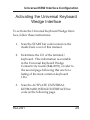
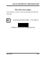
Activating the Universal Keyboard
Wedge Interface
To activate the Universal Keyboard Wedge Interface, follow these instructions:
1.
Scan the START bar code located on the
inside back cover of this manual.
2.
Determine the I.D. of the terminal/
keyboard. This information is available
in the Universal Keyboard Wedge
Connectivity Guide (R44-2039), or refer to
the second page following this one for a
listing of the most common keyboard
I.D.s.
3.
Scan the ACTIVATE UNIVERSAL
KEYBOARD WEDGE INTERFACE bar
code on the following page.
R44-2021
25
Universal KBW Interface Configuration
Activating the Universal KBW I/F - cont.
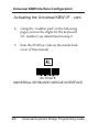
4.
Using the "number pad" on the following
pages, scan in the digits for the keyboard
I.D. number you determined in step 2.
5.
Scan the END bar code on the inside back
cover of this manual.
ACTIVATE
UNIVERSAL KEYBOARD WEDGE INTERFACE
26
Universal Keyboard Wedge Programming Guide
Universal KBW Interface Configuration
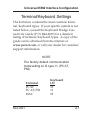
Terminal/Keyboard Settings
The list below contains the most common terminal/keyboard types. If your specific system is not
listed below, consult the Keyboard Wedge Connectivity Guide (P/N R44-2039) for a detailed
listing of terminal/keyboard types. A copy of the
guide can be obtained from the internet at
www.pscnet.com, or call your dealer for customer
support information.
NOTE
The factory default communication
mode setting is I.D. type 11, (PC AT,
PS2).
Terminal
PC XT
PC AT, PS2
MAC
R44-2021
Keyboard
I.D.
10
11
25
27
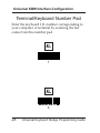
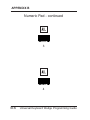
Universal KBW Interface Configuration
Terminal/Keyboard Number Pad
Enter the keyboard I.D. number corresponding to
your computer or terminal by scanning the bar
codes from this number pad.
1
2
28
Universal Keyboard Wedge Programming Guide
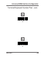
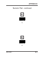
Universal KBW Interface Configuration
Terminal/Keyboard Number Pad - cont.
3
4
R44-2021
29
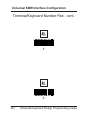
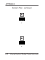
Universal KBW Interface Configuration
Terminal/Keyboard Number Pad - cont.
5
6
30
Universal Keyboard Wedge Programming Guide
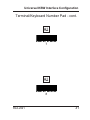
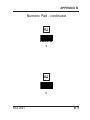
Universal KBW Interface Configuration
Terminal/Keyboard Number Pad - cont.
7
8
R44-2021
31
Universal KBW Interface Configuration
Terminal/Keyboard Number Pad - cont.
9
0
32
Universal Keyboard Wedge Programming Guide
Universal KBW Interface Configuration
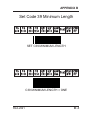
End of Message Characters
You may select one of the END OF MESSAGE
CHARACTERS bar codes from the following
pages to cause the scanner to emulate the selected
characters at the end of each transmitted message.
END OF MESSAGE CHARACTERS = RETURN
NOTE
The factory default setting for this
option is RETURN.
R44-2021
33
Universal KBW Interface Configuration
End of Message Characters - continued
END OF MESSAGE CHARACTERS = ENTER
END OF MESSAGE CHARACTERS = CR/LF
34
Universal Keyboard Wedge Programming Guide
Universal KBW Interface Configuration
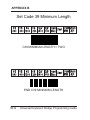
End of Message Characters - continued
END OF MESSAGE CHARACTERS
= FIELD ADVANCE
END OF MESSAGE CHARACTERS
= FIELD EXIT
R44-2021
35
Universal KBW Interface Configuration
End of Message Characters - continued
END OF MESSAGE CHARACTERS = TAB+
END OF MESSAGE CHARACTERS = LF
36
Universal Keyboard Wedge Programming Guide
Universal KBW Interface Configuration
End of Message Characters - continued
END OF MESSAGE CHARACTERS
= NO CHARACTER
R44-2021
37
Universal KBW Interface Configuration
Upper/Lower Case Options
Scan one of the two selections below to select
whether characters are sent as upper or lower case.
UPPER CASE/CAPS – ENABLE
NOTE
The factory default setting for this
option is UPPER CASE/CAPS.
LOWER CASE/SMALL – ENABLE
38
Universal Keyboard Wedge Programming Guide
Universal KBW Interface Configuration
Types of Numeric Characters
This function allows the scanner to emulate either
the numeric characters located on top of the
keyboard or those located on the numeric pad.
Use this function if trouble occurs with upper/
lower case keyboard modes.
NUMERICS LOCATED OVER THE
ALPHANUMERIC PAD
NOTE
This setting is enabled by default.
R44-2021
39
Universal KBW Interface Configuration
Types of Numeric Characters - continued
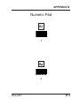
This function allows the scanner to emulate the
numeric characters located on the numeric pad.
NUMERIC PAD
NOTE
If the option “NUMERIC PAD” is
chosen, the numeric pad of the keyboard must be also turned on (locked)
for correct operation (engage "Num
Lock").
40
Universal Keyboard Wedge Programming Guide
Universal KBW Interface Configuration
Intercharacter Delay
Scan the bar code from this and the following
pages to select the desired pause (if any) between
each character before it is sent to the host. This
time delay is used to control the flow of data from
the scanner, but it should not be required for most
applications.
INTERCHARACTER DELAY = 0 ms
INTERCHARACTER DELAY = 5 ms
R44-2021
41
Universal KBW Interface Configuration
Intercharacter Delay - continued
INTERCHARACTER DELAY = 10 ms
INTERCHARACTER DELAY = 20 ms
42
Universal Keyboard Wedge Programming Guide
Universal KBW Interface Configuration
Intercharacter Delay - continued
INTERCHARACTER DELAY = 50 ms
INTERCHARACTER DELAY = 100 ms
R44-2021
43
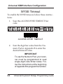
Universal KBW Interface Configuration
WYSE Timeout
To enable the WYSE timeout, follow these instructions:
1. Scan this ACCESS WYSE TIMEOUT bar
code.
ACCESS WYSE TIMEOUT
2.
44
Scan the digit bar codes from the Numeric Pad in Appendix B to enter the
desired timeout value.
IMPORTANT
To use the Numeric Pad, your scanner must be programmed to read
single-digit Code 39 bar codes. Follow the instructions at the beginning
of Appendix B to program this function.
Universal Keyboard Wedge Programming Guide
Universal KBW Interface Configuration
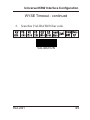
WYSE Timeout - continued
3.
Scan this VALIDATION bar code.
VALIDATION
R44-2021
45
EDITING MODE
Editing Mode
Editing Mode has been designed to offer you
complete flexibility to change the format of the
data input message before transmission to the host
system. Data will be edited when the input data
meets certain criteria defined by the user (MATCH
CONDITION).
Description of Features:
• UP TO FOUR DATA OUTPUT FORMATS can be programmed by the user
and activated by different match conditions.
• MATCH CONDITIONS: up to four
criteria can be accumulated:
— fixed number of characters found.
— pre-defined characters found (up to 3).
46
Universal Keyboard Wedge Programming Guide
EDITING MODE
•
EIGHT EDITING FUNCTIONS can be used
to fix the output data format:
- Divide the message into separate fields (up
to five).
- Add one or two postamble characters to
each field.
- Create additional fixed fields (up to two
fields with six characters maximum).
- Set the number of fields to be transmitted.
- Cancel fields.
- Set the position of the fields in the message
transmitted.
- Activate or deactivate selected formats.
- Transmit data (or not) upon no-match.
R44-2021
47
EDITING MODE
Use of the Numeric Pad
Scanning of number digits is often required while
in Programming Mode (to enter variable data).
You’ll find a handy Numeric Pad in Appendix B.
IMPORTANT
To use the Numeric Pad, your scanner must be programmed to read
single-digit Code 39 bar codes. Follow the instructions at the beginning
of Appendix B to program this function.
48
Universal Keyboard Wedge Programming Guide
EDITING MODE
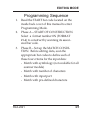
Programming Sequence
1.
2.
3.
Read the START bar code located on the
inside back cover of this manual to enter
Programming Mode.
Phase A -- START OF CONSTRUCTION.
Select a format number #N (FORMAT
#1-4) to construct by scanning its associated bar code.
Phase B -- Set up the MATCH CONDITION. Before editing data, scan the
appropriate bar codes to define each of
these four criteria for the input data:
- Match with symbology (not available for all
scanner models)
- Match with number of characters
- Match with input port
- Match with pre-defined characters
R44-2021
49
EDITING MODE
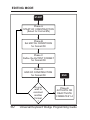
START
Phase A
START OF CONSTRUCTION
(Select for Format #N)
Phase B
Set MATCH CONDITIONS
for Format #N
Phase C
Define the OUTPUT FORMAT
for Format #N
Phase D
END OF CONSTRUCTION
for Format #N
Do you
wish to
construct
another
Format
?
50
END
Phase E
ACTIVATE OR
DEACTIVATE
FORMATS #1-4
Universal Keyboard Wedge Programming Guide
EDITING MODE
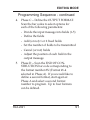
Programming Sequence - continued
4.
5.
Phase C -- Define the OUTPUT FORMAT.
Scan the bar codes to select options for
each of the following parameters:
- Divide the input message into fields (1-5)
- Define the fields
- Add (or not) 1 or 2 fixed fields
- Set the number of fields to be transmitted
- Cancel (or not) fields
- Adjust the position of each field in the
output message.
Phase D -- Scan the END OF CONSTRUCTION bar code corresponding to
the format number #N (Format #1-4
selected in Phase A). If you would like to
define a second format, start again at
Phase A and select a second format
number to program. Up to four formats
can be defined.
R44-2021
51
EDITING MODE
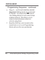
Programming Sequence - continued
6.
7.
52
Phase E -- ACTIVATE EDITING MODE.
Important: Editing mode is not activated
by default. You must activate or deactivate Editing Mode for each of the format
numbers desired. This allows you to
retain format definitions while not
actively using them.
Read the END bar code located on the
inside back cover to exit Programming
Mode and save the new parameters.
Universal Keyboard Wedge Programming Guide
EDITING MODE
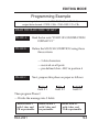
Programming Example
input data received: 123ABC456 (Code 39 label)
output data desired: CODE: C456 <TAB> REF: 123 <CR>
READ THE BAR CODE “START”
PHASE A:
Read the bar code “START OF CONSTRUCTION
FORMAT # 1”
PHASE B:
Define the MATCH CONDITION using these
three criteria
— 9 data characters
— received on all ports
— pre-defined char.: ABC in position 4
PHASE C:
Next, prepare this phase on paper as follows:
123
AB
C456
field # 1
field # 2
field # 3
Then program Phase C
— Divide the message into 3 fields
define field # 1
with 3 char. and
CR as postamble
R44-2021
define field # 2
with 2 char. and
no postamble
define field # 3
with 4 char. and
TAB as postamble
53
EDITING MODE
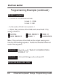
Programaming Example (continued)
PHASE C: continued
— Construct the two additional fixed fields:
fix field # 1: CODE:
fix field # 2: REF:
— Set the number of fields to be transmitted: 4
— Adjust the positions of the fields and cancel field # 2 by
acting as follows:
1 ACCESS
4 ADD. FIELD # 2
2 ADD. FIELD # 1 3 FIELD # 3
5 FIELD # 1
6 VALIDATION
Note: The positions of the fields in the output message are
fixed by the reading sequence. Fields are cancelled when not
read in the sequence.
PHASE D:
Read the code “END OF CONSTRUCTION FORMAT # 1”
PHASE E:
Activate Editing mode on format # 1
READ THE BAR CODE “END”
54
Universal Keyboard Wedge Programming Guide
EDITING MODE
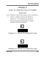
PHASE A
START OF CONSTRUCTION OF NUMBER
SELECTED
Up to 4 different output data formats can be constructed:
•
Select a number and use the labels in
Phases A - D to adjust its parameters,
then come back to this phase to adjust
another format if required.
FORMAT # 1: START OF CONSTRUCTION
FORMAT # 2: START OF CONSTRUCTION
R44-2021
55
EDITING MODE
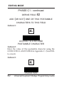
PHASE A - continued
FORMAT # 3: START OF CONSTRUCTION
FORMAT # 4: START OF CONSTRUCTION
56
Universal Keyboard Wedge Programming Guide
EDITING MODE
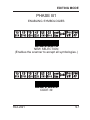
PHASE B1
ENABLING SYMBOLOGIES
NEW SELECTION
(Enables the scanner to accept all symbologies.)
CODE 39
R44-2021
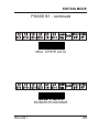
57
EDITING MODE
PHASE B1 - continued
INTERLEAVED 2 OF 5
UPC/EAN
58
Universal Keyboard Wedge Programming Guide
EDITING MODE
PHASE B1 - continued
MAG. STRIPE DATA
MONARCH/CODABAR
R44-2021
59
EDITING MODE
PHASE B1 - continued
CODE 128
EAN 128
60
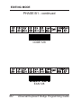
Universal Keyboard Wedge Programming Guide
EDITING MODE
PHASE B1 - continued
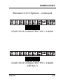
STANDARD 2 OF 5
MSI CODE
R44-2021
61
EDITING MODE
PHASE B1 - continued
PLESSEY
TELEPEN
62
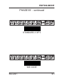
Universal Keyboard Wedge Programming Guide
EDITING MODE
PHASE B1 - continued
CODE 93
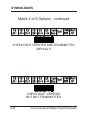
MATRIX 2 OF 5
R44-2021
63
EDITING MODE
PHASE B1 - continued
IATA
BC412
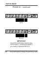
IMPORTANT
Use of this symbology requires specific firmware. Consult your dealer if
you need to implement BC412.
64
Universal Keyboard Wedge Programming Guide
EDITING MODE
PHASE B1 - continued
PHARMACODE
3W7
R44-2021
65
EDITING MODE
PHASE B1 - continued
RESERVED #1
RESERVED #2
66
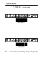
Universal Keyboard Wedge Programming Guide
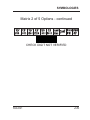
EDITING MODE
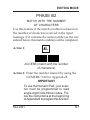
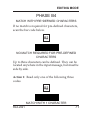
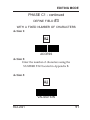
PHASE B2
MATCH WITH THE NUMBER
OF CHARACTERS
Use this feature if the match condition is based on
the number of characters received in the input
message. If it contains the same number as the one
entered below, this match condition will be completed.
Action 1:
ACCESS (match with the number
of characters)
Action 2: Enter the number desired by using the
NUMERIC PAD in Appendix B.
IMPORTANT
To use the Numeric Pad, your scanner must be programmed to read
single-digit Code 39 bar codes. Follow the instructions at the beginning
of Appendix B to program this function.
R44-2021
67
EDITING MODE
PHASE B2 - continued
MATCH WITH THE NUMBER
OF CHARACTERS
Action 3:
VALIDATION
If no match is desired with the number of characters, scan the bar code below.
VARIABLE NUMBER ACCEPTED
68
Universal Keyboard Wedge Programming Guide
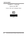
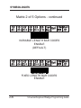
EDITING MODE
PHASE B3
MATCH WITH INPUT PORT
ALL PORTS
PORT J1
R44-2021
69
EDITING MODE
PHASE B3 - continued
RS-232 DATA RECEIVED ON J1 or C2
70
Universal Keyboard Wedge Programming Guide
EDITING MODE
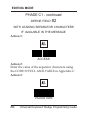
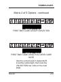
PHASE B4
MATCH WITH PRE-DEFINED CHARACTERS
If no match is required for pre-defined characters,
scan the bar code below.
NO MATCH REQUIRED FOR PRE-DEFINED
CHARACTERS
Up to three characters can be defined. They can be
located anywhere in the input message, but must be
side by side.
Action 1: Read only one of the following three
codes.
MATCH WITH 1 CHARACTER
R44-2021
71
EDITING MODE
PHASE B4 - continued
MATCH WITH PRE-DEFINED CHARACTERS
Action 1: (Continued)
MATCH WITH 2 CHARACTERS
MATCH WITH 3 CHARACTERS
72
Universal Keyboard Wedge Programming Guide
EDITING MODE
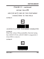
PHASE B4 - continued
MATCH WITH PRE-DEFINED CHARACTERS
Action 2:
Pre-define the characters (s) desired
by scanning the corresponding
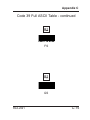
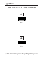
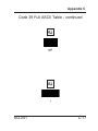
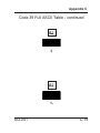
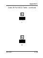
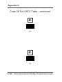
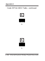
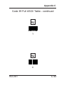
characters from the Code 39 FULL
ASCII TABLE in Appendix C.
Action 3:
VALIDATION
R44-2021
73
EDITING MODE
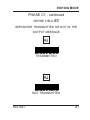
PHASE B4 - continued
POSITION OF THE FIRST PRE-DEFINED
CHARACTER IN THE INPUT MESSAGE
Action 1:
ACCESS
Action 2:
Enter the position desired using the
NUMBER PAD located in Appendix B.
Action 3:
VALIDATION
74
Universal Keyboard Wedge Programming Guide
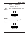
EDITING MODE
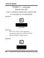
PHASE C0
DIVIDE THE INPUT
MESSAGE INTO FIELDS
Before starting this phase, it is advisable to prepare it on paper.
• Write down the input message and
separate it into fields.
• Mark each field with a number from 1 to
5 maximum starting at the left hand
side of the message.
• Enter the number of fields resulting from
the division of the input message
including the fields which do not require
transmission.
• Define each necessary field using the
Phase C1 selections.
R44-2021
75
EDITING MODE
PHASE C0- continued
DIVIDE THE INPUT
MESSAGE INTO FIELDS
ONLY ONE FIELD
2 FIELDS
76
Universal Keyboard Wedge Programming Guide
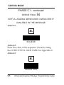
EDITING MODE
PHASE C0- continued
DIVIDE THE INPUT
MESSAGE INTO FIELDS
3 FIELDS
4 FIELDS
R44-2021
77
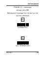
EDITING MODE
PHASE C0- continued
DIVIDE THE INPUT
MESSAGE INTO FIELDS
5 FIELDS
78
Universal Keyboard Wedge Programming Guide
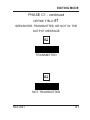
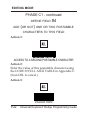
EDITING MODE
PHASE C1
DEFINE FIELD #1
WITH A FIXED NUMBER OF CHARACTERS
Action 1:
ACCESS
Action 2:
Enter the number of characters using the
NUMBER PAD located in Appendix B.
Action 3:
VALIDATION
R44-2021
79
EDITING MODE
PHASE C1 - continued
DEFINE FIELD
#1
WITH A LEADING SEPARATOR CHARACTER
IF AVAILABLE IN THE MESSAGE
Action 1:
ACCESS
Action 2:
Enter the value of the separator
characters using the CODE 39 FULL
ASCII TABLE in Appendix C.
Action 3:
VALIDATION
80
Universal Keyboard Wedge Programming Guide
EDITING MODE
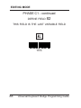
PHASE C1 - continued
DEFINE FIELD
#1
SEPARATOR TRANSMITTED OR NOT IN THE
OUTPUT MESSAGE
TRANSMITTED
NOT TRANSMITTED
R44-2021
81
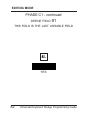
EDITING MODE
PHASE C1 - continued
DEFINE FIELD
#1
THIS FIELD IS THE LAST VARIABLE FIELD
YES
82
Universal Keyboard Wedge Programming Guide
EDITING MODE
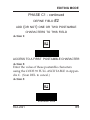
PHASE C1 - continued
DEFINE FIELD
#1
ADD (OR NOT) ONE OR TWO POSTAMBLE
CHARACTERS TO THIS FIELD
Action 1:
ACCESS TO A 1ST POSTAMBLE CHARACTER
Action 2:
Enter the value of this postamble character using
the CODE 39 FULL ASCII TABLE in Appendix C.
(Scan DEL to cancel.)
Action 3:
VALIDATION
R44-2021
83
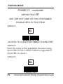
EDITING MODE
PHASE C1 - continued
DEFINE FIELD
#1
ADD (OR NOT) ONE OR TWO POSTAMBLE
CHARACTERS TO THIS FIELD
Action 1:
ACCESS TO A 2ND POSTAMBLE CHARACTER
Action 2:
Enter the value of this postamble character using
the CODE 39 FULL ASCII TABLE in Appendix C.
(Scan DEL to cancel.)
Action 3:
VALIDATION
84
Universal Keyboard Wedge Programming Guide
EDITING MODE
PHASE C1 - continued
DEFINE FIELD
#2
WITH A FIXED NUMBER OF CHARACTERS
Action 1:
ACCESS
Action 2:
Enter the number of characters using the
NUMBER PAD located in Appendix B.
Action 3:
VALIDATION
R44-2021
85
EDITING MODE
PHASE C1 - continued
DEFINE FIELD
#2
WITH LEADING SEPARATOR CHARACTERS
IF AVAILABLE IN THE MESSAGE
Action 1:
ACCESS
Action 2:
Enter the value of the separator characters using
the CODE 39 FULL ASCII TABLE in Appendix C.
Action 3:
VALIDATION
86
Universal Keyboard Wedge Programming Guide
EDITING MODE
PHASE C1 - continued
DEFINE FIELD
#2
SEPARATOR TRANSMITTED OR NOT IN THE
OUTPUT MESSAGE
TRANSMITTED
NOT TRANSMITTED
R44-2021
87
EDITING MODE
PHASE C1 - continued
DEFINE FIELD
#2
THIS FIELD IS THE LAST VARIABLE FIELD
YES
88
Universal Keyboard Wedge Programming Guide
EDITING MODE
PHASE C1 - continued
DEFINE FIELD
#2
ADD (OR NOT) ONE OR TWO POSTAMBLE
CHARACTERS TO THIS FIELD
Action 1:
ACCESS TO A FIRST POSTAMBLE CHARACTER
Action 2:
Enter the value of these postamble characters
using the CODE 39 FULL ASCII TABLE in Appendix C. (Scan DEL to cancel.)
Action 3:
VALIDATION
R44-2021
89
EDITING MODE
PHASE C1 - continued
DEFINE FIELD
#2
ADD (OR NOT) ONE OR TWO POSTAMBLE
CHARACTERS TO THIS FIELD
Action 1:
ACCESS TO A SECOND
POSTAMBLE CHARACTER
Action 2:
Enter the value of this postamble character using the
CODE 39 FULL ASCII TABLE in Appendix C. (Scan DEL
to cancel.)
Action 3:
VALIDATION
90
Universal Keyboard Wedge Programming Guide
EDITING MODE
PHASE C1 - continued
DEFINE FIELD
#3
WITH A FIXED NUMBER OF CHARACTERS
Action 1:
ACCESS
Action 2:
Enter the number of characters using the
NUMBER PAD located in Appendix B.
Action 3:
VALIDATION
R44-2021
91
EDITING MODE
PHASE C1 - continued
DEFINE FIELD
#3
WITH LEADING SEPARATOR CHARACTERS
IF AVAILABLE IN THE MESSAGE
Action 1:
ACCESS
Action 2:
Enter the value of the separator character(s) using
the CODE 39 FULL ASCII TABLE in Appendix C.
Action 3:
VALIDATION
92
Universal Keyboard Wedge Programming Guide
EDITING MODE
PHASE C1 - continued
DEFINE FIELD
#3
SEPARATOR TRANSMITTED OR NOT IN THE
OUTPUT MESSAGE
TRANSMITTED
NOT TRANSMITTED
R44-2021
93
EDITING MODE
PHASE C1 - continued
DEFINE FIELD
#3
THIS IS THE LAST VARIABLE FIELD
YES
94
Universal Keyboard Wedge Programming Guide
EDITING MODE
PHASE C1 - continued
DEFINE FIELD
#3
ADD (OR NOT) ONE OR TWO POSTAMBLE
CHARACTERS TO THIS FIELD
Action 1:
ACCESS TO A FIRST POSTAMBLE CHARACTER
Action 2:
Enter the value of this postamble character using
the CODE 39 FULL ASCII TABLE in Appendix C.
(Scan DEL to cancel.)
Action 3:
VALIDATION
R44-2021
95
EDITING MODE
PHASE C1 - continued
DEFINE FIELD
#3
ADD (OR NOT) ONE OR TWO POSTAMBLE
CHARACTERS TO THIS FIELD
Action 1:
ACCESS TO A 2ND POSTAMBLE CHARACTER
Action 2:
Enter the value of this postamble character using
the CODE 39 FULL ASCII TABLE in Appendix C.
(Scan DEL to cancel.)
Action 3:
VALIDATION
96
Universal Keyboard Wedge Programming Guide
EDITING MODE
PHASE C1 - continued
DEFINE FIELD
#4
WITH A FIXED NUMBER OF CHARACTERS
Action 1:
ACCESS
Action 2:
Enter the number of characters using the
NUMBER PAD located in Appendix B.
Action 3:
VALIDATION
R44-2021
97
EDITING MODE
PHASE C1 - continued
DEFINE FIELD
#4
WITH A LEADING SEPARATOR CHARACTER IF
AVAILABLE IN THE MESSAGE
Action 1:
ACCESS
Action 2:
Enter the value of the separator character using
the CODE 39 FULL ASCII TABLE in Appendix C.
Action 3:
VALIDATION
98
Universal Keyboard Wedge Programming Guide
EDITING MODE
PHASE C1 - continued
DEFINE FIELD
#4
SEPARATOR TRAMSMITTED OR NOT IN THE
OUTPUT MESSAGE
TRANSMITTED
NOT TRANSMITTED
R44-2021
99
EDITING MODE
PHASE C1 - continued
DEFINE FIELD
#4
THIS FIELD IS THE LAST VARIABLE FIELD
YES
100
Universal Keyboard Wedge Programming Guide
EDITING MODE
PHASE C1 - continued
DEFINE FIELD
#4
ADD (OR NOT) ONE OR TWO POSTAMBLE
CHARACTERS TO THIS FIELD
Action 1:
ACCESS TO A FIRST POSTAMBLE CHARACTER
Action 2:
Enter the value of this postamble character using
the CODE 39 FULL ASCII TABLE in Appendix C.
(Scan DEL to cancel.)
Action 3:
VALIDATION
R44-2021
101
EDITING MODE
PHASE C1 - continued
DEFINE FIELD
#4
ADD (OR NOT) ONE OR TWO POSTAMBLE
CHARACTERS TO THIS FIELD
Action 1:
ACCESS TO A SECOND POSTAMBLE CHARACTER
Action 2:
Enter the value of this postamble character using
the CODE 39 FULL ASCII TABLE in Appendix C.
(Scan DEL to cancel.)
Action 3:
VALIDATION
102
Universal Keyboard Wedge Programming Guide
EDITING MODE
PHASE C1 - continued
DEFINE FIELD
#5
WITH A FIXED NUMBER OF CHARACTERS
Action 1:
ACCESS
Action 2:
Enter the number of characters using the
NUMBER PAD located in Appendix B.
Action 3:
VALIDATION
R44-2021
103
EDITING MODE
PHASE C1 - continued
DEFINE FIELD
#5
WITH A LEADING SEPARATOR CHARACTER
IF AVAILABLE IN THE MESSAGE
Action 1:
ACCESS
Action 2:
Enter the value of the separator character using
the CODE 39 FULL ASCII TABLE in Appendix C.
Action 3:
VALIDATION
104
Universal Keyboard Wedge Programming Guide
EDITING MODE
PHASE C1 - continued
DEFINE FIELD
#5
SEPARATOR TRANSMITTED OR NOT
IN THE OUTPUT MESSAGE
TRANSMITTED
NOT TRANSMITTED
R44-2021
105
EDITING MODE
PHASE C1 - continued
DEFINE FIELD
#5
THIS FIELD IS THE LAST VARIABLE FIELD
YES
106
Universal Keyboard Wedge Programming Guide
EDITING MODE
PHASE C1 - continued
DEFINE FIELD
#5
ADD (OR NOT) ONE OR TWO POSTAMBLE
CHARACTERS TO THIS FIELD
Action 1:
ACCESS TO A FIRST POSTAMBLE CHARACTER
Action 2:
Enter the value of this postamble character using
the CODE 39 FULL ASCII TABLE in Appendix C.
(Scan DEL to cancel.)
Action 3:
VALIDATION
R44-2021
107
EDITING MODE
PHASE C1 - continued
DEFINE FIELD
#5
ADD (OR NOT) ONE OR TWO POSTAMBLE
CHARACTERS TO THIS FIELD
Action 1:
ACCESS TO A SECOND POSTAMBLE CHARACTER
Action 2:
Enter the value of this postamble character using
the CODE 39 FULL ASCII TABLE in Appendix C.
(Scan DEL to cancel.)
Action 3:
VALIDATION
108
Universal Keyboard Wedge Programming Guide
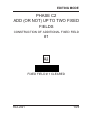
EDITING MODE
PHASE C2
ADD (OR NOT) UP TO TWO FIXED
FIELDS
CONSTRUCTION OF ADDITIONAL FIXED FIELD
#1
FIXED FIELD # 1 CLEARED
R44-2021
109
EDITING MODE
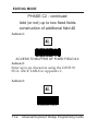
PHASE C2 - continued
add (or not) up to two fixed fields
construction of additional field #1
Action 1:
ACCESS TO BUFFER OF FIXED FIELD # 1
Action 2:
Enter up to six characters using the CODE 39
FULL ASCII TABLE in Appendix C.
Action 3:
VALIDATION
110
Universal Keyboard Wedge Programming Guide
EDITING MODE
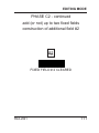
PHASE C2 - continued
add (or not) up to two fixed fields
construction of additional field #2
FIXED FIELD # 2 CLEARED
R44-2021
111
EDITING MODE
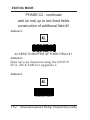
PHASE C2 - continued
Add (or not) up to two fixed fields
construction of additional field #2
Action 1:
ACCESS TO BUFFER OF FIXED FIELD # 2
Action 2:
Enter up to six characters using the CODE 39
FULL ASCII TABLE in Appendix C.
Action 3:
VALIDATION
112
Universal Keyboard Wedge Programming Guide
EDITING MODE
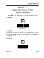
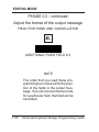
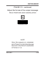
PHASE C3
Adjust the format of the
output message
NUMBER OF FIELDS TO BE TRANSMITTED
Action 1:
ACCESS
Action 2:
Enter the number of fields to be transmitted in the
output message using the NUMBER PAD located
in Appendix B.
Action 3:
VALIDATION
R44-2021
113
EDITING MODE
PHASE C3 - continued
Adjust the format of the output message
FIELD POSITION AND CANCELLATION
ACCESS
NOTE
The order that you read these programming bar codes will fix the position of the fields in the output message. If you do not scan the bar code
for a particular field, that field will be
cancelled.
114
Universal Keyboard Wedge Programming Guide
EDITING MODE
PHASE C3 - continued
Adjust the format of the output message
FIELD POSITIONS AND CANCELLATION
FIELD # 1
FIELD # 2
NOTE
The order that you read these programming bar codes will fix the position of the fields in the output message. If you do not scan the bar code
for a particular field, that field will be
cancelled.
R44-2021
115
EDITING MODE
PHASE C3 - continued
Adjust the format of the output message
FIELD POSITIONS AND CANCELLATION
FIELD # 3
FIELD # 4
NOTE
The order that you read these programming bar codes will fix the position of the fields in the output message. If you do not scan the bar code
for a particular field, that field will be
cancelled.
116
Universal Keyboard Wedge Programming Guide
EDITING MODE
PHASE C3 - continued
Adjust the format of the output message
FIELD POSITIONS AND CANCELLATION
FIELD # 5
ADDITIONAL FIXED FIELD # 1
NOTE
The order that you read these programming bar codes will fix the position of the fields in the output message. If you do not scan the bar code
for a particular field, that field will be
cancelled.
R44-2021
117
EDITING MODE
PHASE C3 - continued
Adjust the format of the output message
FIELD POSITIONS AND CANCELLATION
ADDITIONAL FIXED FIELD # 2
NOTE
The order that you read these programming bar codes will fix the position of the fields in the output message. If you do not scan the bar code
for a particular field, that field will be
cancelled.
118
Universal Keyboard Wedge Programming Guide
EDITING MODE
PHASE C3 - continued
Adjust the format of the output message
FIELD POSITIONS AND CANCELLATION
VALIDATION
NOTE
Once this sequence is completed,
go to Phase D on the following page
and scan in the End of Construction
of Format # 1-4.
R44-2021
119
EDITING MODE
PHASE D
End of construction
END OF CONSTRUCTION, FORMATS # 1 – 4
IMPORTANT NOTE
Once this phase is completed for a
format number:
• Go back to Phase A to define another
format if required.
• Or go to the next section to activate
Editing Mode for the format number(s)
desired.
120
Universal Keyboard Wedge Programming Guide
EDITING MODE
PHASE E
Activate editing mode
IMPORTANT NOTE
Editing mode is not activated by default. You must
activate or deactivate Editing Mode for each of the
format numbers desired using these bar codes.
This allows you to retain format definitions while
not actively using them.
Once programmed, the different formats can be
activated or deactivated at any time during operation. When a format is deactivated, its parameters
are saved in the non-volatile EEprom memory of the
decoder and are recalled when the format number is
re-activated.
EDITING MODE DEACTIVATED for ALL formats
R44-2021
121
EDITING MODE
PHASE E - continued
Activate editing mode
ACTIVATED FOR FORMAT # 1
ACTIVATED FOR FORMAT # 2
122
Universal Keyboard Wedge Programming Guide
EDITING MODE
PHASE E - continued
Activate editing mode
ACTIVATED FOR FORMAT # 3
ACTIVATED FOR FORMAT # 4
R44-2021
123
EDITING MODE
PHASE E - continued
Activate editing mode
DEACTIVATED FOR FORMAT # 1
DEACTIVATED FOR FORMAT # 2
124
Universal Keyboard Wedge Programming Guide
EDITING MODE
PHASE E - continued
Activate editing mode
DEACTIVATED FOR FORMAT # 3
DEACTIVATED FOR FORMAT # 4
R44-2021
125
EDITING MODE
Match Not Performed
Two possibilities are offered when a match is not
performed on the input data:
• Data is transmitted to the host system in
its original format.
STRAIGHT-THRU TRANSMISSION
OF THE INPUT DATA
•
Data is cleared and not transmitted.
NO TRANSMISSION OF THE INPUT DATA
126
Universal Keyboard Wedge Programming Guide
RS-232 INTERFACE CONFIGURATION
RS-232 Interface
Configuration
The following pages provide instructions to configure RS-232 interface communications options for
scanners equipped with the Universal Keyboard
Wedge Interface.
NOTE
The RS-232 interface features provided in this section are an enhanced
set that are only available for scanners equipped with the Universal
Keyboard Wedge interface.
R44-2021
127
RS-232 INTERFACE CONFIGURATION
RS-232 Interface Configuration
The programming bar codes in this section pertain
only to POS terminals with an RS-232 communication interface. In order for the POS terminal and
scanner to communicate, the scanner's configuration
must match the communication settings of the POS
terminal.
128
Universal Keyboard Wedge Programming Guide
RS-232 INTERFACE CONFIGURATION
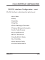
RS-232 Interface Configuration - cont.
RS-232 Interface communication options are:
• Baud Rate
• Parity
• Data Bits
• Stop Bits
• End of Message Characters
• Timeout Between Characters
• ACK/NAK Protocol
• Xon/Xoff Protocol
• RTS/CTS Protocol
• Double RS-232 Mode
• In/Out Mode
• Intercharacter Delay
• Full ASCII Emulation
R44-2021
129
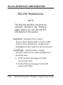
RS-232 INTERFACE CONFIGURATION
RS-232 Restrictions
NOTE
The RS-232 interface must first be
selected (reference the following
page) before you can set the RS232 options in this section.
Xon/Xoff – Software flow control.
Xon (11 hex); Host ready to receive data.
Xoff (13 hex); Host busy, wedge stops
transmission and waits for Xon from host.
ACK/NAK – Software flow control.
Decoder waits for an acknowledgement
from the host.
• ACK (06 hex); message correctly
received by host.
• NAK (15 hex); message incorrectly
received by host.
130
Universal Keyboard Wedge Programming Guide
RS-232 INTERFACE CONFIGURATION
RS-232 Activation
Scan this bar code to activate (enable) the RS-232
interface.
(except QuickScan 6000 = TTL ONLY)
ENABLE [Universal Wedge] RS-232
R44-2021
131
RS-232 INTERFACE CONFIGURATION
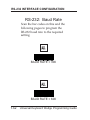
RS-232: Baud Rate
Scan the bar codes on this and the
following pages to program the
RS-232 baud rate to the required
setting.
BAUD RATE = 300
BAUD RATE = 600
132
Universal Keyboard Wedge Programming Guide
RS-232 INTERFACE CONFIGURATION
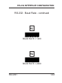
RS-232: Baud Rate - continued
BAUD RATE = 1200
BAUD RATE = 2400
R44-2021
133
RS-232 INTERFACE CONFIGURATION
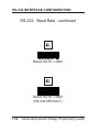
RS-232: Baud Rate - continued
BAUD RATE = 4800
BAUD RATE = 9600
(RS-232 DEFAULT)
134
Universal Keyboard Wedge Programming Guide
RS-232 INTERFACE CONFIGURATION
RS-232: Baud Rate - continued
Baud Rate: 19200
Baud Rate: 38400
R44-2021
135
RS-232 INTERFACE CONFIGURATION
RS-232: Parity
Scan the bar code on this or the
following page to select the
correct RS-232 parity.
PARITY = ODD
PARITY = MARK
136
Universal Keyboard Wedge Programming Guide
RS-232 INTERFACE CONFIGURATION
RS-232: Parity - continued
PARITY = SPACE
PARITY = EVEN
(RS-232 DEFAULT)
R44-2021
137
RS-232 INTERFACE CONFIGURATION
RS-232: Data Bits
Scan the bar code from this page
to select the correct RS-232 Data
Bits setting.
DATA BITS = 7
(RS-232 DEFAULT)
DATA BITS = 8
138
Universal Keyboard Wedge Programming Guide
RS-232 INTERFACE CONFIGURATION
RS-232: Stop Bits
Scan the bar code from this page
to select the correct RS-232 Stop
Bits setting.
STOP BITS = 1
(RS-232 DEFAULT)
STOP BITS = 2
R44-2021
139
RS-232 INTERFACE CONFIGURATION
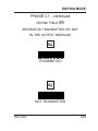
RS-232: End of Message Characters
Scan the bar code from this and
the following pages to select the
desired End of Message Character.
END OF MESSAGE CHARACTERS = NONE
END OF MESSAGE CHARACTERS
= SUITE (MINITEL)
140
Universal Keyboard Wedge Programming Guide
RS-232 INTERFACE CONFIGURATION
RS-232: End of Message Characters continued
END OF MESSAGE CHARACTERS = CR
END OF MESSAGE CHARACTERS = LF
R44-2021
141
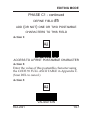
RS-232 INTERFACE CONFIGURATION
RS-232: End of Message Characters continued
END OF MESSAGE CHARACTERS = HT
END OF MESSAGE CHARACTERS = EOT
142
Universal Keyboard Wedge Programming Guide
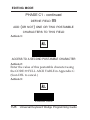
RS-232 INTERFACE CONFIGURATION
RS-232: End of Message Characters continued
END OF MESSAGE CHARACTERS = STX...ETX
END OF MESSAGE CHARACTERS = CR/LF
(RS-232 DEFAULT)
R44-2021
143
RS-232 INTERFACE CONFIGURATION
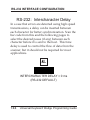
RS-232: Intercharacter Delay
In a case that errors are detected using high speed
transmissions, a delay can be inserted between
each character for better synchronization. Scan the
bar code from this and the following pages to
select the desired pause (if any) between each
character before it is sent to the host. This time
delay is used to control the flow of data from the
scanner, but it should not be required for most
applications.
INTERCHARACTER DELAY = 0 ms
(RS-232 DEFAULT)
144
Universal Keyboard Wedge Programming Guide
RS-232 INTERFACE CONFIGURATION
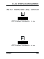
RS-232: Intercharacter Delay - continued
INTERCHARACTER DELAY = 10 ms
INTERCHARACTER DELAY = 20 ms
R44-2021
145
RS-232 INTERFACE CONFIGURATION
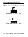
RS-232: Intercharacter Delay - continued
INTERCHARACTER DELAY = 50 ms
INTERCHARACTER DELAY = 100 ms
146
Universal Keyboard Wedge Programming Guide
RS-232 INTERFACE CONFIGURATION
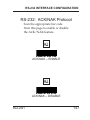
RS-232: ACK/NAK Protocol
Scan the appropriate bar code
from this page to enable or disable
the ACK/NAK feature.
ACK/NAK – ENABLE
ACK/NAK – DISABLE
R44-2021
147
RS-232 INTERFACE CONFIGURATION
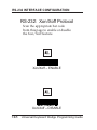
RS-232: Xon/Xoff Protocol
Scan the appropriate bar code
from this page to enable or disable
the Xon/Xoff feature.
Xon/Xoff – ENABLE
Xon/Xoff – DISABLE
148
Universal Keyboard Wedge Programming Guide
RS-232 INTERFACE CONFIGURATION
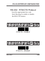
RS-232: RTS/CTS Protocol
Scan the appropriate bar code
from this page to enable or disable
the RTS/CTS feature.
RTS/CTS – ENABLE
RTS/CTS – DISABLE
R44-2021
149
RS-232 INTERFACE CONFIGURATION
Features on this page are supported with cable 6015-0490.
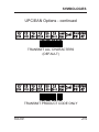
Double RS-232 PC Term Mode –
Activate
Some applications use several RS-232 terminals
connected to a PC host system configured in PC
Term mode. When a character is typed on a
keyboard of a terminal, its scan code value is
transmitted to the PC instead of its ASCII value.
Then, upon reception, the PC sends back the
corresponding ASCII character to display on the
screen.
Therefore, once this mode is activated, the decoder
sends the scan code value of each character read.
BB+ and BBX supports this mode using the cable
6015-0490. The BI+ also supports it while connected in Double RS-232 mode.
150
Universal Keyboard Wedge Programming Guide
RS-232 INTERFACE CONFIGURATION
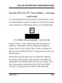
Double RS-232 PC-Term Mode – Activate
continued
To activate the PC-Term mode, read this bar code.
It is advisable to insert a timeout of 50 ms between
each character when baud rate is over 9600 baud.
PC-TERM RS-232 MODE – ACTIVATE
Upper/lower case characters and the type of
numeric characters can be adjusted using the
Upper/Lower Case Options bar codes contained in
the Universal KBW Interface Configuration section of
this manual.
Keyboard layout style can be selected without
scanning "keyboard wedge mode activated" by
using the Termimal/Keyboard Settings Number Pad
bar codes also contained in the Universal KBW
Interface Configuration section of this manual.
R44-2021
151
RS-232 INTERFACE CONFIGURATION
RS-232 In/Out Mode – Activate
Scan the bar code below to
activate the RS-232 In/Out Mode.
RS-232 IN/OUT MODE – ACTIVATE
152
Universal Keyboard Wedge Programming Guide
RS-232 INTERFACE CONFIGURATION
RS-232: Full ASCII Emulation
Once enabled, this function will convert each
couple of characters from the Code 39 Full ASCII
table.
RS-232 FULL ASCII MODE – ENABLE
RS-232 FULL ASCII MODE – DISABLE
R44-2021
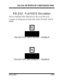
153
WAND EMULATION I/F CONFIGURATION
Wand Emulation
Interface Configuration
This following pages provide instructions to configure Wand Emulation interface communications
options for scanners equipped with the Universal
Keyboard Wedge Interface.
NOTE
The Wand Emulation interface features provided in this section are an
enhanced set that are only available
for scanners equipped with the Universal Keyboard Wedge interface.
154
Universal Keyboard Wedge Programming Guide
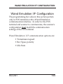
WAND EMULATION I/F CONFIGURATION
Wand Emulation I/F Configuration
The programming bar codes in this section pertain
only to POS terminals with a Wand Emulation
communication interface. In order for the POS
terminal and scanner to communicate, the scanner's
configuration must match the communication
settings of the POS terminal.
Wand Emulation I/F communication options are:
• Transmission speed
• Bar/Space polarity
• Idle State
R44-2021
155
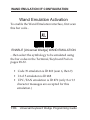
WAND EMULATION I/F CONFIGURATION
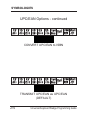
Wand Emulation Activation
To enable the Wand Emulation interface, first scan
this bar code...
ENABLE [Universal Wedge] WAND EMULATION
...then select the symbology to be emulated using
the bar codes in the Terminal/Keyboard Pad on
pages 28-32.
• Code 39 emulation is ID #69 (scan 6, then 9)
• I 2 of 5 emulation is ID #68
• UPC/EAN emulation is ID #70 (only 8 or 13
character messages are accepted for this
emulation.)
156
Universal Keyboard Wedge Programming Guide
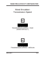
WAND EMULATION I/F CONFIGURATION
Wand Emulation:
Transmission Speed
TRANSMISSION SPEED = HIGH
(WAND DEFAULT)
TRANSMISSION SPEED = MEDIUM
R44-2021
157
WAND EMULATION I/F CONFIGURATION
Wand Emulation:
Transmission Speed - continued
TRANSMISSION SPEED = LOW
158
Universal Keyboard Wedge Programming Guide
WAND EMULATION I/F CONFIGURATION
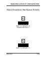
Wand Emulation: Bar/Space Polarity
BAR = 1, SPACE = 0
(WAND DEFAULT)
BAR = 0, SPACE = 1
R44-2021
159
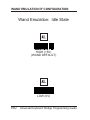
WAND EMULATION I/F CONFIGURATION
Wand Emulation: Idle State
HIGH (+5V)
(WAND DEFAULT)
LOW (0V)
160
Universal Keyboard Wedge Programming Guide
SYMBOLOGIES
Symbologies
Symbology selection (bar code type) determines
which symbologies the scanner will decode. Once
you have determined the symbologies you wish to
enable, turn to the following pages, enable those
symbologies and set the data format options (e.g.
check digit, start/stop characters, etc.) required by
your host system for each symbology type. You
must enable the symbology format options
settings that are compatible with your host
system.
NOTE
If your scanner does not support
symbology selection, only the factory default symbologies pre-set with
standard industry requirements will
be available. Contact your dealer if
you are unsure about your scanner's
default settings.
Be sure to test the scanner using factory settings
before making any changes.
R44-2021
161
SYMBOLOGIES
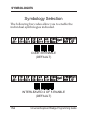
Symbology Selection
The following bar codes allow you to enable the
individual symbologies indicated.
CODE 39 ENABLE
(DEFAULT)
INTERLEAVED 2 OF 5 ENABLE
(DEFAULT)
162
Universal Keyboard Wedge Programming Guide
SYMBOLOGIES
Symbology Selection - continued
UPC/EAN ENABLE
(DEFAULT)
MONARCH/CODABAR ENABLE
(DEFAULT)
R44-2021
163
SYMBOLOGIES
Symbology Selection - continued
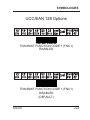
CODE 128 ENABLE
(DEFAULT)
EAN 128 ENABLE
(DEFAULT)
164
Universal Keyboard Wedge Programming Guide
SYMBOLOGIES
Symbology Selection - continued
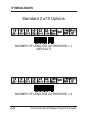
STANDARD 2 OF 5 ENABLE
MSI ENABLE
R44-2021
165
SYMBOLOGIES
Symbology Selection - continued
PLESSEY ENABLE
TELEPEN ENABLE
166
Universal Keyboard Wedge Programming Guide
SYMBOLOGIES
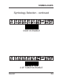
Symbology Selection - continued
CODE 93 ENABLE
2 OF 5 MATRIX ENABLE
R44-2021
167
SYMBOLOGIES
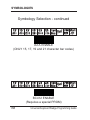
Symbology Selection - continued
IATA ENABLE
(ONLY 15, 17, 19 and 21 character bar codes)
BC412 ENABLE
(Requires a special PROM)
168
Universal Keyboard Wedge Programming Guide
SYMBOLOGIES
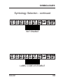
Symbology Selection - continued
3W7 ENABLE
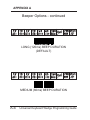
LABEL CODE 4/5 ENABLE
R44-2021
169
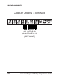
SYMBOLOGIES
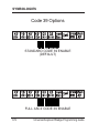
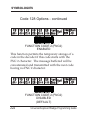
Code 39 Options
STANDARD CODE 39 ENABLE
(DEFAULT)
FULL ASCII CODE 39 ENABLE
170
Universal Keyboard Wedge Programming Guide
SYMBOLOGIES
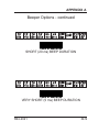
Code 39 Options -- continued
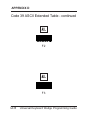
FULL ASCII EXTENDED - DISABLE
(DEFAULT)
FULL ASCII EXTENDED Active on 2 Characters preceded by a dash.
R44-2021
171
SYMBOLOGIES
Code 39 Options -- continued
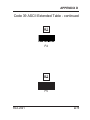
FULL ASCII EXTENDED Active on 2 Characters.
FULL ASCII EXTENDED Active ONLY on 2 Characters separate from the
symbol.
172
Universal Keyboard Wedge Programming Guide
SYMBOLOGIES
Code 39 Options -- continued
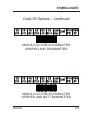
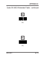
EMULATE FUNCTION KEYS - ENABLE
Once enabled, this function will convert each
couple of characters from the Code 39 FULL ASCII
EXTENDED table.
EMULATE FUNCTION KEYS - DISABLE
R44-2021
173
SYMBOLOGIES
Code 39 Options -- continued
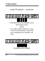
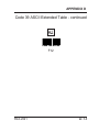
FULL ASCII EMULATION - DISABLE
Once enabled, this function will convert each
couple of characters from the Code 39 FULL ASCII
table for support of F1 - F10 and more.
FULL ASCII EMULATION - ENABLE
174
Universal Keyboard Wedge Programming Guide
SYMBOLOGIES
Code 39 Options -- continued
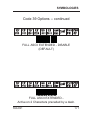
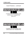
START/STOP TRANSMITTED
START/STOP NOT TRANSMITTED
R44-2021
175
SYMBOLOGIES
Code 39 Options -- continued
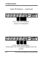
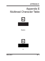
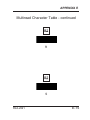
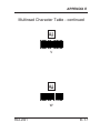
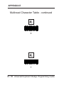
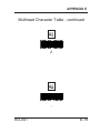
The multi-read function permits the temporary
storage of one or more codes in the decoder's
memory which will then be transmitted in a single
string message.
To operate the multi-read function, the desired
group of codes to be first stored must have a
mulit-read character as the leading character. This
character can be chosen in the multi-read table
inAppendix E after scanning the MULTI-READ
ENABLED bar code (default is SPACE character).
The transmission will start once a code having no
multiread character is read.
176
Universal Keyboard Wedge Programming Guide
SYMBOLOGIES
Code 39 Options -- continued
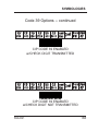
MULTI-READ ENABLED
MULTI-READ DISABLED
(DEFAULT)
R44-2021
177
SYMBOLOGIES
Code 39 Options -- continued
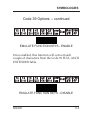
In the case of high-level security applications, a
check character can be integrated as the last
character in the code and verified before transmission.
MODULO 43 CHECK CHARACTER
NOT VERIFIED
178
Universal Keyboard Wedge Programming Guide
SYMBOLOGIES
Code 39 Options -- continued
MODULO 43 CHECK CHARACTER
VERIFIED AND TRANSMITTED
MODULO 43 CHECK CHARACTER
VERIFIED AND NOT TRANSMITTED
R44-2021
179
SYMBOLOGIES
Code 39 Options -- continued
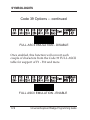
PHARMACODE OR PHARMA 32/39
NEW SELECTION
NOTE
The NEW SELECTION bar code
must be scanned prior to scanning
the PHARMACODE ENABLE bar
code.
PHARMACODE ENABLE
180
Universal Keyboard Wedge Programming Guide
SYMBOLOGIES
Code 39 Options -- continued
PHARMACODE OR PHARMA 32/39
START/STOP TRANSMITTED
PHARMACODE OR PHARMA 32/39
START/STOP NOT TRANSMITTED
(DEFAULT)
R44-2021
181
SYMBOLOGIES
Code 39 Options -- continued
PHARMACODE OR PHARMA 32/39
CHECK DIGIT TRANSMITTED
(DEFAULT)
PHARMACODE OR PHARMA 32/39
CHECK DIGIT NOT TRANSMITTED
182
Universal Keyboard Wedge Programming Guide
SYMBOLOGIES
Code 39 Options -- continued
CIP CODE 39 ENABLED
w/CHECK DIGIT TRANSMITTED
CIP CODE 39 ENABLED
w/CHECK DIGIT NOT TRANSMITTED
R44-2021
183
SYMBOLOGIES
Code 39 Options -- continued
CIP CODE 39
(ALL CODES 39)
(DEFAULT)
184
Universal Keyboard Wedge Programming Guide
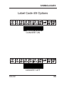
SYMBOLOGIES
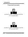
Label Code 4/5 Options
CONVERT ON
CONVERT OFF
R44-2021
185
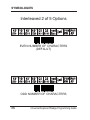
SYMBOLOGIES
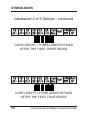
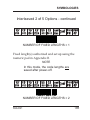
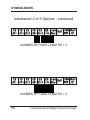
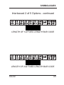
Interleaved 2 of 5 Options
EVEN NUMBER OF CHARACTERS
(DEFAULT)
ODD NUMBER OF CHARACTERS
186
Universal Keyboard Wedge Programming Guide
SYMBOLOGIES
Interleaved 2 of 5 Options - continued
CODE LENGTH = ONE LENGTH FIXED AFTER
THE FIRST READ
(DEFAULT)
Fixed length(s) authorized and set upon first
reading(s) after power-on.
NOTE
In this mode, the code lengths are
not saved after power-off.
CODE LENGTH = TWO LENGTHS FIXED AFTER
THE FIRST TWO READS
R44-2021
187
SYMBOLOGIES
Interleaved 2 of 5 Options - continued
CODE LENGTH = THREE LENGTHS FIXED
AFTER THE FIRST THREE READS
CODE LENGTH = FOUR LENGTHS FIXED
AFTER THE FIRST FOUR READS
188
Universal Keyboard Wedge Programming Guide
SYMBOLOGIES
Interleaved 2 of 5 Options - continued
NUMBER OF FIXED LENGTHS = 1
Fixed length(s) authorized and set up using the
numeric pad in Appendix B.
NOTE
In this mode, the code lengths are
saved after power-off.
NUMBER OF FIXED LENGTHS = 2
R44-2021
189
SYMBOLOGIES
Interleaved 2 of 5 Options - continued
NUMBER OF FIXED LENGTHS = 3
NUMBER OF FIXED LENGTHS = 4
190
Universal Keyboard Wedge Programming Guide
SYMBOLOGIES
Interleaved 2 of 5 Options - continued
LENGTH OF 1st FIXED LENGTH BAR CODE
LENGTH OF 2nd FIXED LENGTH BAR CODE
R44-2021
191
SYMBOLOGIES
Interleaved 2 of 5 Options - continued
LENGTH OF 3rd FIXED LENGTH BAR CODE
LENGTH OF 4th FIXED LENGTH BAR CODE
192
Universal Keyboard Wedge Programming Guide
SYMBOLOGIES
Interleaved 2 of 5 Options - continued
Enter the desired fixed length(s) using the numeric
pad in Appendix B, then scan the VALIDATION
bar code below.
VALIDATION
VARIABLE LENGTHS ENABLED
R44-2021
193
SYMBOLOGIES
Interleaved 2 of 5 Options - continued
CHECK DIGIT
VERIFIED AND TRANSMITTED
CHECK DIGIT
VERIFIED BUT NOT TRANSMITTED
194
Universal Keyboard Wedge Programming Guide
SYMBOLOGIES
Interleaved 2 of 5 Options - continued
CIP CHECK DIGIT
VERIFIED AND TRANSMITTED
CIP CHECK DIGIT
VERIFIED BUT NOT TRANSMITTED
R44-2021
195
SYMBOLOGIES
Interleaved 2 of 5 Options - continued
CHECK DIGIT NOT VERIFIED
(DEFAULT)
WARNING
This mode is not advised. Missing
characters can occur in the case of
incomplete scanning of a bar code.
196
Universal Keyboard Wedge Programming Guide
SYMBOLOGIES
UPC/EAN Options
ALL UPC/EAN CODES AUTHORIZED
(DEFAULT)
EAN 13 AUTHORIZED
R44-2021
197
SYMBOLOGIES
UPC/EAN Options - continued
UPC-A AUTHORIZED
EAN 8 AUTHORIZED
198
Universal Keyboard Wedge Programming Guide
SYMBOLOGIES
UPC/EAN Options - continued
UPC-E AUTHORIZED
TRANSMIT UPC AS EAN
(DEFAULT)
R44-2021
199
SYMBOLOGIES
UPC/EAN Options - continued
TRANSMIT UPC AS UPC
TRANSMIT UPC-E AS UPC-E
(DEFAULT)
200
Universal Keyboard Wedge Programming Guide
SYMBOLOGIES
UPC/EAN Options - continued
TRANSMIT UPC-E AS UPC-A
TRANSMIT ADDON
R44-2021
201
SYMBOLOGIES
UPC/EAN Options - continued
DON'T TRANSMIT ADDON
(DEFAULT)
ADDON OPTIONAL
(DEFAULT)
202
Universal Keyboard Wedge Programming Guide
SYMBOLOGIES
UPC/EAN Options - continued
ADDON REQUIRED
2 OR 5 CHARACTER ADDON
(DEFAULT)
R44-2021
203
SYMBOLOGIES
UPC/EAN Options - continued
2 CHARACTER ADDON ONLY
5 CHARACTER ADDON ONLY
204
Universal Keyboard Wedge Programming Guide
SYMBOLOGIES
UPC/EAN Options - continued
EAN 13 ADDON (378 OR 379 PREFIX)
ENABLED
EAN 13 ADDON (378 OR 379 PREFIX)
DISABLED
(DEFAULT)
R44-2021
205
SYMBOLOGIES
UPC/EAN Options - continued
TRANSMIT PREFIXES
DON'T TRANSMIT PREFIXES
(DEFAULT)
206
Universal Keyboard Wedge Programming Guide
SYMBOLOGIES
UPC/EAN Options - continued
TRANSMIT EAN 13 FLAG
(DEFAULT)
DON'T TRANSMIT EAN 13 FLAG
R44-2021
207
SYMBOLOGIES
UPC/EAN Options - continued
TRANSMIT EAN 8 FLAG
(DEFAULT)
DON'T TRANSMIT EAN 8 FLAG
208
Universal Keyboard Wedge Programming Guide
SYMBOLOGIES
UPC/EAN Options - continued
TRANSMIT UPC-A FLAG
(DEFAULT)
DON'T TRANSMIT UPC-A FLAG
R44-2021
209
SYMBOLOGIES
UPC/EAN Options - continued
TRANSMIT UPC-E FLAG
(DEFAULT)
DON'T TRANSMIT UPC-E FLAG
210
Universal Keyboard Wedge Programming Guide
SYMBOLOGIES
UPC/EAN Options - continued
TRANSMIT EAN 13 CHECK DIGIT
(DEFAULT)
DON'T TRANSMIT EAN 13 CHECK DIGIT
R44-2021
211
SYMBOLOGIES
UPC/EAN Options - continued
TRANSMIT UPC-A CHECK DIGIT
(DEFAULT)
DON'T TRANSMIT UPC-A CHECK DIGIT
212
Universal Keyboard Wedge Programming Guide
SYMBOLOGIES
UPC/EAN Options - continued
TRANSMIT EAN 8 CHECK DIGIT
(DEFAULT)
DON'T TRANSMIT EAN 8 CHECK DIGIT
R44-2021
213
SYMBOLOGIES
UPC/EAN Options - continued
TRANSMIT UPC-E CHECK DIGIT
(DEFAULT)
DON'T TRANSMIT UPC-E CHECK DIGIT
214
Universal Keyboard Wedge Programming Guide
SYMBOLOGIES
UPC/EAN Options - continued
TRANSMIT ALL CHARACTERS
(DEFAULT)
TRANSMIT PRODUCT CODE ONLY
R44-2021
215
SYMBOLOGIES
UPC/EAN Options - continued
CONVERT UPC/EAN to ISBN
TRANSMIT UPC/EAN as UPC/EAN
(DEFAULT)
216
Universal Keyboard Wedge Programming Guide
SYMBOLOGIES
Codabar Options
TRANSMIT START/STOP CHARACTERS
DON'T TRANSMIT START/STOP CHARACTERS
(DEFAULT)
R44-2021
217
SYMBOLOGIES
Codabar Options - continued
abcd (small) START/STOP CHARACTERS
ENABLE
(DEFAULT)
ABCD (CAPs) START/STOP CHARACTERS
ENABLE
218
Universal Keyboard Wedge Programming Guide
SYMBOLOGIES
Codabar Options - continued
CONCATENATION OF TWO BAR CODES
ENABLE
(bar code 1 must end with the character 'd' and
bar code 2 must start with the character 'd')
(DEFAULT)
STANDARD
R44-2021
219
SYMBOLOGIES
Code 128 Options
CHECK CHARACTER VERIFIED
AND TRANSMITTED
CHECK CHARACTER VERIFIED
BUT NOT TRANSMITTED
(DEFAULT)
220
Universal Keyboard Wedge Programming Guide
SYMBOLOGIES
Code 128 Options - continued
CHECK CHARACTER NOT VERIFIED
BUT TRANSMITTED
R44-2021
221
SYMBOLOGIES
Code 128 Options - continued
FUNCTION CODE 2 (FNC2)
ENABLED
This function permits the temporary storage of a
code in the decoder if this code starts with the
FNC 2 character. The message buffered will be
concatenated and transmitted with the next code
having no FNC 2 character.
FUNCTION CODE 2 (FNC2)
DISABLED
(DEFAULT)
222
Universal Keyboard Wedge Programming Guide
SYMBOLOGIES
UCC/EAN 128 Options
TRANSMIT FUNCTION CODE 1 (FNC1)
ENABLED
TRANSMIT FUNCTION CODE 1 (FNC1)
DISABLED
(DEFAULT)
R44-2021
223
SYMBOLOGIES
Standard 2 of 5 Options
NUMBER OF LENGTHS AUTHORIZED = 1
(DEFAULT)
NUMBER OF LENGTHS AUTHORIZED = 2
224
Universal Keyboard Wedge Programming Guide
SYMBOLOGIES
Standard 2 of 5 Options - continued
START/STOP CHARACTER TYPE = 2 BARS
START/STOP CHARACTER TYPE = 3 BARS
(DEFAULT)
R44-2021
225
SYMBOLOGIES
MSI Options
VARIABLE LENGTH BAR CODES
ENABLE
(DEFAULT)
ENABLE ONE FIXED LENGTH SET BY
READING A BAR CODE AFTER POWER-ON
NOTE
Length is not saved after power-off.
226
Universal Keyboard Wedge Programming Guide
SYMBOLOGIES
MSI Options - continued
DOUBLE CHECK DIGIT (Modulo 10)
VERIFIED AND BOTH TRANSMITTED
DOUBLE CHECK DIGIT (Modulo 10)
VERIFIED BUT NOT TRANSMITTED
(DEFAULT)
R44-2021
227
SYMBOLOGIES
MSI Options - continued
DOUBLE CHECK DIGIT (Modulo 10)
BOTH VERIFIED
BUT ONLY THE FIRST ONE TRANSMITTED
DOUBLE CHECK DIGIT NOT VERIFIED
228
Universal Keyboard Wedge Programming Guide
SYMBOLOGIES
MSI Options - continued
SINGLE CHECK DIGIT (Modulo 10)
VERIFIED AND TRANSMITTED
SINGLE CHECK DIGIT (Modulo 10)
VERIFIED BUT NOT TRANSMITTED
R44-2021
229
SYMBOLOGIES
Plessey Code Options
TRANSMIT CHECK DIGITS
(DEFAULT)
DON'T TRANSMIT CHECK DIGITS
230
Universal Keyboard Wedge Programming Guide
SYMBOLOGIES
Telepen Code Options
ALPHANUMERIC CHARACTERS
ENABLE
(DEFAULT)
NUMERIC CHARACTERS ONLY
ENABLE
R44-2021
231
SYMBOLOGIES
Code 93 Options
MULTIREAD ENABLED
(DEFAULT)
MULTIREAD DISABLED
(Multiread permits the decoder to concatenate bar
codes that start with a space character. These will
be transmitted upon reading a bar code having no
leading space character.)
232
Universal Keyboard Wedge Programming Guide
SYMBOLOGIES
Matrix 2 of 5 Options
START/STOP CHARACTER TYPE = 2 BARS
START/STOP CHARACTER TYPE = 3 BARS
(DEFAULT)
R44-2021
233
SYMBOLOGIES
Matrix 2 of 5 Options - continued
CHECK DIGIT VERIFIED AND TRANSMITTED
(DEFAULT)
CHECK DIGIT VERIFIED
BUT NOT TRANSMITTED
234
Universal Keyboard Wedge Programming Guide
SYMBOLOGIES
Matrix 2 of 5 Options - continued
CHECK DIGIT NOT VERIFIED
R44-2021
235
SYMBOLOGIES
Matrix 2 of 5 Options - continued
VARIABLE LENGTH BAR CODES
ENABLE
(DEFAULT)
FIXED LENGTH BAR CODES
ENABLE
236
Universal Keyboard Wedge Programming Guide
SYMBOLOGIES
Matrix 2 of 5 Options - continued
FIRST BAR CODE LENGTH SELECTED
FIRST BAR CODE LENGTH ACCESS CODE
NOTE
Use the numeric pad in Appendix B
to set the code length, then scan the
VALIDATION bar code on the next
page.
R44-2021
237
SYMBOLOGIES
Matrix 2 of 5 Options - continued
VALIDATION
238
Universal Keyboard Wedge Programming Guide
SYMBOLOGIES
Matrix 2 of 5 Options - continued
SECOND BAR CODE LENGTH SELECTED
SECOND BAR CODE LENGTH ACCESS CODE
NOTE
Use the numeric pad in Appendix B
to set the code length, then scan the
VALIDATION bar code on the next
page.
R44-2021
239
SYMBOLOGIES
Matrix 2 of 5 Options - continued
VALIDATION
240
Universal Keyboard Wedge Programming Guide
SYMBOLOGIES
BC412 Options
TRANSMIT CHECK DIGIT
DON'T TRANSMIT CHECK DIGIT
(DEFAULT)
R44-2021
241
SYMBOLOGIES
Decoding Selectivity
MINIMUM SELECTIVITY
(One bar code, one decode)
MAXIMUM SELECTIVITY
(Three bar code captures, three decodes)
242
Universal Keyboard Wedge Programming Guide
SYMBOLOGIES
SP4RF
Symbology Leading Identifiers
Symbology-specific label identifiers comprise one
or two ASCII characters that can precede or
follow bar code label data as it is transmitted to
the host. The host uses these characters to distinguish between symbologies.
Industry standards have been established for
symbology-specific label identifiers, and are listed
in the table below. Most scanners will have
factory default identifiers preset to these standards.
Programming of label identifiers for some products will require use of additional manuals. Refer
to page 13.
R44-2021
243
SYMBOLOGIES
Symbology Leading Identifiers - continued
DON'T TRANSMIT LEADING ID'S W/ONE CHARACTER
List of Identifiers
Code 39
Interleaved 2 of 5
UPC/EAN
Codabar
Code 128
EAN 128
Standard 2 of 5
MSI Code
Plessey Code
Telepen Code
A
I
E
F
C
J
R
M
P
B
Code 93
Matrix 2 of 5
IATA
3W7
Pharmacode
Reserved # 1
Reserved # 2
Reserved # 3
RS232 data received
Mag. stripe data
G
Q
T
X
S
V
W
Y
Z
D
Table 1. Industry Standard Label Identifiers (all are prefixes)
TRANSMIT LEADING ID'S W/ONE CHARACTER
244
Universal Keyboard Wedge Programming Guide
SYMBOLOGIES
Three Character AIM Identifier
TRANSMIT
IDENTIFIER WITH THREE CHARACTERS
The first character is ] (5Dhex), the second identifies the type of symbology read, and the third
indicates an option in the symbology. Refer to the
AIM standard.
DON'T TRANSMIT
IDENTIFIER WITH THREE CHARACTERS
(DEFAULT)
R44-2021
245
SYMBOLOGIES
Decoding Selectivity
MINIMUM SELECTIVITY
(One bar code capture, one decode)
(DEFAULT)
MAXIMUM SELECTIVITY
(Three bar code captures, three decode)
246
Universal Keyboard Wedge Programming Guide
APPENDIX A
Appendix A
Misc. Features
Contents
BEEPER OPTIONS ................................................. A-2
PREAMBLE/POSTAMBLE .......................................... A-6
CONVERSION OF CHARACTERS ................................ A-9
ROLLING BUFFER MODE ...................................... A-15
BEEP UPON "BEL" (O7H) RECEIVED .................... A-21
SCANNER RELEASED BY HOST .............................. A-22
TRANSMISSION OF THE FULL ASCII ....................... A-25
LOCKING ACCESS TO PROGRAMMING ....................... A-26
DISPLAYING THE FIRMWARE LEVEL .......................... A-30
R44-2021
A-1
APPENDIX A
Beeper Options
HIGH SOUND VOLUME
(DEFAULT)
MEDIUM SOUND VOLUME
A-2
Universal Keyboard Wedge Programming Guide
APPENDIX A
Beeper Options - continued
LOW SOUND VOLUME
SOUND VOLUME OFF
R44-2021
A-3
APPENDIX A
Beeper Options - continued
LONG (120ms) BEEP DURATION
(DEFAULT)
MEDIUM (60ms) BEEP DURATION
A-4
Universal Keyboard Wedge Programming Guide
APPENDIX A
Beeper Options - continued
SHORT (20 ms) BEEP DURATION
VERY SHORT (5 ms) BEEP DURATION
R44-2021
A-5
APPENDIX A
Preamble/Postamble
ACCESS TO PORT J1 PREAMBLE BUFFER
(TTL input data ONLY)
ACCESS TO PORT J1 POSTAMBLE BUFFER
(TTL input data ONLY)
A-6
Universal Keyboard Wedge Programming Guide
APPENDIX A
Preamble/Postamble - continued
ACCESS TO
PREAMBLE BUFFERS OF ALL PORTS
(Characters will be stored in ALL preamble buffers)
ACCESS TO
POSTAMBLE BUFFERS OF ALL PORTS
(Characters will be stored in ALL postamble buffers)
R44-2021
A-7
APPENDIX A
Preamble/Postamble - continued
CLEAR BUFFER PRE-SELECTED
TRANSMIT PRE/POSTAMBLE CHARACTERS
A-8
Universal Keyboard Wedge Programming Guide
APPENDIX A
Conversion of Characters
FIRST CHARACTER TO BE CONVERTED
Scan the character from the Code 39 Full ASCII
TABLE located in Appendix C, then scan the
VALIDATION bar code.
VALIDATION
R44-2021
A-9
APPENDIX A
Conversion of Characters - continued
NEW FIRST CHARACTER DESIRED ACCESS
Scan the character from the Code 39
Full ASCII TABLE located in
Appendix C, then scan the VALIDATION bar code.
VALIDATION
A-10
Universal Keyboard Wedge Programming Guide
APPENDIX A
Conversion of Characters - continued
CLEAR CONVERSION OF FIRST CHARACTER
R44-2021
A-11
APPENDIX A
Conversion of Characters - continued
SECOND CHARACTER TO BE CONVERTED
ACCESS
Scan the character from the Code 39
Full ASCII TABLE located in
Appendix C, then scan the VALIDATION bar code.
VALIDATION
A-12
Universal Keyboard Wedge Programming Guide
APPENDIX A
Conversion of Characters - continued
NEW SECOND CHARACTER DESIRED
ACCESS
Scan the character from the Code 39
Full ASCII TABLE located in
Appendix C, then scan the VALIDATION bar code.
VALIDATION
R44-2021
A-13
APPENDIX A
Conversion of Characters - continued
CLEAR CONVERSION OF
SECOND CHARACTER
A-14
Universal Keyboard Wedge Programming Guide
APPENDIX A
Rolling Buffer Mode
In this mode, input data is stored in a buffer (up to
3K characters) and transmitted at a fixed timeout
selected with this section.
NO TIMEOUT
TIMEOUT = 100 ms
R44-2021
A-15
APPENDIX A
Rolling Buffer Mode - continued
TIMEOUT = 200 ms
TIMEOUT = 500 ms
A-16
Universal Keyboard Wedge Programming Guide
APPENDIX A
Rolling Buffer Mode - continued
TIMEOUT = 700 ms
TIMEOUT = 1 SECOND
R44-2021
A-17
APPENDIX A
Rolling Buffer Mode - continued
TIMEOUT = 1.5 SECONDS
TIMEOUT = 2 SECONDS
A-18
Universal Keyboard Wedge Programming Guide
APPENDIX A
Rolling Buffer Mode - continued
TIMEOUT = 3 SECONDS
TIMEOUT = 5 SECONDS
R44-2021
A-19
APPENDIX A
Rolling Buffer Mode - continued
TIMEOUT = 7 SECONDS
TIMEOUT = 10 SECONDS
A-20
Universal Keyboard Wedge Programming Guide
APPENDIX A
Beep Emitted Upon "BEL" (O7h)
Received
NOT ACTIVATED
ACTIVATED
R44-2021
A-21
APPENDIX A
Scanner Released by Host
This function allows an RS-232 host to enable/
disable input messages by sending programmable
ASCII characters.
NOT ACTIVATED
ACTIVATED
A-22
Universal Keyboard Wedge Programming Guide
APPENDIX A
Scanner Released by Host - continued
SELECT THE "ON" CHARACTER
Scan the character from the Code 39
Full ASCII TABLE located in
Appendix C, then scan the VALIDATION bar code.
VALIDATION
R44-2021
A-23
APPENDIX A
Scanner Released by Host - continued
SELECT THE "OFF" CHARACTER
Scan the character from the Code 39
Full ASCII TABLE located in
Appendix C.
VALIDATION
A-24
Universal Keyboard Wedge Programming Guide
APPENDIX A
Transmission of the Full ASCII
Character Set
Read the START label on the
inside back cover.
ACTIVATED
The scanner will return to normal
Operational Mode when all 96
characters are transmitted.
R44-2021
A-25
APPENDIX A
Lock Access to Programming
The LOCK ACCESS feature allows an administrator to control access to scanner programming.
To lock access to programming, follow this
procedure:
1. Scan the START bar code on the inside
back cover.
2.
Scan this PROGRAMMING LOCKED bar
code.
PROGRAMMING LOCKED
3.
A-26
Scan the END bar code on the inside back
cover.
Universal Keyboard Wedge Programming Guide
APPENDIX A
Lock Access to Programming - continued
To unlock access to programming, follow this
procedure:
1. Scan this UNLOCK ACCESS bar code.
2.
3.
4.
UNLOCK ACCESS
Scan the START bar code on the inside
back cover.
Scan this PROGRAMMING RE-AUTHORIZED bar code.
PROGRAMMING RE-AUTHORIZED
Scan the END bar code on the inside back
cover.
R44-2021
A-27
APPENDIX A
Displaying the Firmware Level
Once the scanner is connected to a host system
with communication parameters correctly adjusted, the level of the firmware implemented in
the scanner can be displayed as follows:
1.
Read the START bar code on the inside
back cover.
2.
Scan this DISPLAY FIRMWARE LEVEL
bar code.
DISPLAY FIRMWARE LEVEL
Once the DISPLAY FIRMWARE LEVEL bar code
is read, the firmware level is transmitted and the
decoder returns to its previous operational mode.
A-28
Universal Keyboard Wedge Programming Guide
APPENDIX A
Displaying the Firmware Level - continued
The message will appear as follows:
FIRMWARE LEVEL: XXX.XX
If the SMARTY adapter is attached to the decoder,
the message will include both the decoder and the
smarty firmware levels as follows:
FIRMWARE LEVEL: XXX.XX
R44-2021
+ SXX.XX
A-29
APPENDIX A
NOTES
A-30
Universal Keyboard Wedge Programming Guide
APPENDIX B
Appendix B
Numeric Pad
The bar codes in this section provide a handy way
to program numeric information into the scanner.
NOTE
Certain scanner models have been
programmed by factory default to
decode Code 39 bar codes with a
minimum length of two digits, and
will require reprogramming to allow
the scanner to read single-digit bar
codes. See the following page for
instructions to change Code 39 minimum length.
R44-2021
B-1
APPENDIX B
Set Code 39 Minimum Length
To allow the indicated scanner models to read
single-digit bar codes...
• Scan the SET C39 MINIMUM LENGTH
bar code on the next page.
• Scan the C39 MINIMUM LENGTH = ONE
bar code.
• Scan the END C39 MINIMUM LENGTH bar
code on the second page following this page.
Reset Code 39 Minimum Length
After you’ve completed programming all scanner
features that required you to read single-digit bar
codes, you may want to reset the scanner with a
two-digit minimum length for Code 39 bar codes.
• Scan the SET C39 MINIMUM LENGTH
bar code on the next page.
• Scan the C39 MINIMUM LENGTH =
TWO bar code on the second page
following this page.
• Scan the END C39 MINIMUM LENGTH bar
code on the second page following this page.
B-2
Universal Keyboard Wedge Programming Guide
APPENDIX B
Set Code 39 Minimum Length
SET C39 MINIMUM LENGTH
C39 MINIMUM LENGTH = ONE
R44-2021
B-3
APPENDIX B
Set Code 39 Minimum Length
C39 MINIMUM LENGTH = TWO
END C39 MINIMUM LENGTH
B-4
Universal Keyboard Wedge Programming Guide
APPENDIX B
Numeric Pad
1
2
R44-2021
B-5
APPENDIX B
Numeric Pad - continued
3
4
B-6
Universal Keyboard Wedge Programming Guide
APPENDIX B
Numeric Pad - continued
5
6
R44-2021
B-7
APPENDIX B
Numeric Pad - continued
7
8
B-8
Universal Keyboard Wedge Programming Guide
APPENDIX B
Numeric Pad - continued
9
0
R44-2021
B-9
APPENDIX B
NOTES
B-10
Universal Keyboard Wedge Programming Guide
Appendix C
Appendix C
Code 39 Full ASCII Table
NUL
SOH
R44-2021
C-1
Appendix C
Code 39 Full ASCII Table - continued
STX
ETX
C-2
Universal Keyboard Wedge Programming Guide
Appendix C
Code 39 Full ASCII Table - continued
EOT
ENQ
R44-2021
C-3
Appendix C
Code 39 Full ASCII Table - continued
ACK
BEL
C-4
Universal Keyboard Wedge Programming Guide
Appendix C
Code 39 Full ASCII Table - continued
BS
HT
R44-2021
C-5
Appendix C
Code 39 Full ASCII Table - continued
LF
VT
C-6
Universal Keyboard Wedge Programming Guide
Appendix C
Code 39 Full ASCII Table - continued
FF
CR
R44-2021
C-7
Appendix C
Code 39 Full ASCII Table - continued
SO
SI
C-8
Universal Keyboard Wedge Programming Guide
Appendix C
Code 39 Full ASCII Table - continued
DLE
DC1
R44-2021
C-9
Appendix C
Code 39 Full ASCII Table - continued
DC2
DC3
C-10
Universal Keyboard Wedge Programming Guide
Appendix C
Code 39 Full ASCII Table - continued
DC4
NAK
R44-2021
C-11
Appendix C
Code 39 Full ASCII Table - continued
SYN
ETB
C-12
Universal Keyboard Wedge Programming Guide
Appendix C
Code 39 Full ASCII Table - continued
CAN
EM
R44-2021
C-13
Appendix C
Code 39 Full ASCII Table - continued
SUB
ESC
C-14
Universal Keyboard Wedge Programming Guide
Appendix C
Code 39 Full ASCII Table - continued
FS
GS
R44-2021
C-15
Appendix C
Code 39 Full ASCII Table - continued
RS
US
C-16
Universal Keyboard Wedge Programming Guide
Appendix C
Code 39 Full ASCII Table - continued
SP
!
R44-2021
C-17
Appendix C
Code 39 Full ASCII Table - continued
"
#
C-18
Universal Keyboard Wedge Programming Guide
Appendix C
Code 39 Full ASCII Table - continued
$
%
R44-2021
C-19
Appendix C
Code 39 Full ASCII Table - continued
&
’
(closing single quote)
C-20
Universal Keyboard Wedge Programming Guide
Appendix C
Code 39 Full ASCII Table - continued
(
)
R44-2021
C-21
Appendix C
Code 39 Full ASCII Table - continued
*
+
C-22
Universal Keyboard Wedge Programming Guide
Appendix C
Code 39 Full ASCII Table - continued
,
(Comma)
(Dash)
R44-2021
C-23
Appendix C
Code 39 Full ASCII Table - continued
.
(Period)
/
C-24
Universal Keyboard Wedge Programming Guide
Appendix C
Code 39 Full ASCII Table - continued
0
1
R44-2021
C-25
Appendix C
Code 39 Full ASCII Table - continued
2
3
C-26
Universal Keyboard Wedge Programming Guide
Appendix C
Code 39 Full ASCII Table - continued
4
5
R44-2021
C-27
Appendix C
Code 39 Full ASCII Table - continued
6
7
C-28
Universal Keyboard Wedge Programming Guide
Appendix C
Code 39 Full ASCII Table - continued
8
9
R44-2021
C-29
Appendix C
Code 39 Full ASCII Table - continued
:
(Colon)
;
(Semi-colon)
C-30
Universal Keyboard Wedge Programming Guide
Appendix C
Code 39 Full ASCII Table - continued
<
=
R44-2021
C-31
Appendix C
Code 39 Full ASCII Table - continued
>
?
C-32
Universal Keyboard Wedge Programming Guide
Appendix C
Code 39 Full ASCII Table - continued
@
A
R44-2021
C-33
Appendix C
Code 39 Full ASCII Table - continued
B
C
C-34
Universal Keyboard Wedge Programming Guide
Appendix C
Code 39 Full ASCII Table - continued
D
E
R44-2021
C-35
Appendix C
Code 39 Full ASCII Table - continued
F
G
C-36
Universal Keyboard Wedge Programming Guide
Appendix C
Code 39 Full ASCII Table - continued
H
I
R44-2021
C-37
Appendix C
Code 39 Full ASCII Table - continued
J
K
C-38
Universal Keyboard Wedge Programming Guide
Appendix C
Code 39 Full ASCII Table - continued
L
M
R44-2021
C-39
Appendix C
Code 39 Full ASCII Table - continued
N
O
C-40
Universal Keyboard Wedge Programming Guide
Appendix C
Code 39 Full ASCII Table - continued
P
Q
R44-2021
C-41
Appendix C
Code 39 Full ASCII Table - continued
R
S
C-42
Universal Keyboard Wedge Programming Guide
Appendix C
Code 39 Full ASCII Table - continued
T
U
R44-2021
C-43
Appendix C
Code 39 Full ASCII Table - continued
V
W
C-44
Universal Keyboard Wedge Programming Guide
Appendix C
Code 39 Full ASCII Table - continued
X
Y
R44-2021
C-45
Appendix C
Code 39 Full ASCII Table - continued
Z
[
C-46
Universal Keyboard Wedge Programming Guide
Appendix C
Code 39 Full ASCII Table - continued
\
]
R44-2021
C-47
Appendix C
Code 39 Full ASCII Table - continued
^
(Dash)
C-48
Universal Keyboard Wedge Programming Guide
Appendix C
Code 39 Full ASCII Table - continued
‘
(opening single quote)
a
R44-2021
C-49
Appendix C
Code 39 Full ASCII Table - continued
b
c
C-50
Universal Keyboard Wedge Programming Guide
Appendix C
Code 39 Full ASCII Table - continued
d
e
R44-2021
C-51
Appendix C
Code 39 Full ASCII Table - continued
f
g
C-52
Universal Keyboard Wedge Programming Guide
Appendix C
Code 39 Full ASCII Table - continued
h
i
R44-2021
C-53
Appendix C
Code 39 Full ASCII Table - continued
j
k
C-54
Universal Keyboard Wedge Programming Guide
Appendix C
Code 39 Full ASCII Table - continued
l
m
R44-2021
C-55
Appendix C
Code 39 Full ASCII Table - continued
n
o
C-56
Universal Keyboard Wedge Programming Guide
Appendix C
Code 39 Full ASCII Table - continued
p
q
R44-2021
C-57
Appendix C
Code 39 Full ASCII Table - continued
r
s
C-58
Universal Keyboard Wedge Programming Guide
Appendix C
Code 39 Full ASCII Table - continued
t
u
R44-2021
C-59
Appendix C
Code 39 Full ASCII Table - continued
v
w
C-60
Universal Keyboard Wedge Programming Guide
Appendix C
Code 39 Full ASCII Table - continued
x
y
R44-2021
C-61
Appendix C
Code 39 Full ASCII Table - continued
z
{
C-62
Universal Keyboard Wedge Programming Guide
Appendix C
Code 39 Full ASCII Table - continued
|
(Pipe Character)
}
R44-2021
C-63
Appendix C
Code 39 Full ASCII Table - continued
~
DEL
C-64
Universal Keyboard Wedge Programming Guide
APPENDIX D
Appendix D
Code 39 ASCII
Extended Table
FIELD EXIT
FIELD ADVANCE
R44-2021
D-1
APPENDIX D
Code 39 ASCII Extended Table - continued
ENTER
SEND
D-2
Universal Keyboard Wedge Programming Guide
APPENDIX D
Code 39 ASCII Extended Table - continued
TAB
RETURN
R44-2021
D-3
APPENDIX D
Code 39 ASCII Extended Table - continued
RESET, RESTORE
HOME
D-4
Universal Keyboard Wedge Programming Guide
APPENDIX D
Code 39 ASCII Extended Table - continued
RIGHT ARROW
LEFT ARROW
R44-2021
D-5
APPENDIX D
Code 39 ASCII Extended Table - continued
UP ARROW
DOWN ARROW
D-6
Universal Keyboard Wedge Programming Guide
APPENDIX D
Code 39 ASCII Extended Table - continued
CLEAR
F1
R44-2021
D-7
APPENDIX D
Code 39 ASCII Extended Table - continued
F2
F3
D-8
Universal Keyboard Wedge Programming Guide
APPENDIX D
Code 39 ASCII Extended Table - continued
F4
F5
R44-2021
D-9
APPENDIX D
Code 39 ASCII Extended Table - continued
F6
F7
D-10
Universal Keyboard Wedge Programming Guide
APPENDIX D
Code 39 ASCII Extended Table - continued
F8
F9
R44-2021
D-11
APPENDIX D
Code 39 ASCII Extended Table - continued
F10
F11
D-12
Universal Keyboard Wedge Programming Guide
APPENDIX D
Code 39 ASCII Extended Table - continued
F12
R44-2021
D-13
APPENDIX D
NOTES
D-14
Universal Keyboard Wedge Programming Guide
APPENDIX E
Appendix E
Multiread Character Table
Space
0
R44-2021
E-1
APPENDIX E
Multiread Character Table - continued
1
2
E-2
Universal Keyboard Wedge Programming Guide
APPENDIX E
Multiread Character Table - continued
3
4
R44-2021
E-3
APPENDIX E
Multiread Character Table - continued
5
6
E-4
Universal Keyboard Wedge Programming Guide
APPENDIX E
Multiread Character Table - continued
7
8
R44-2021
E-5
APPENDIX E
Multiread Character Table - continued
9
A
E-6
Universal Keyboard Wedge Programming Guide
APPENDIX E
Multiread Character Table - continued
B
C
R44-2021
E-7
APPENDIX E
Multiread Character Table - continued
D
E
E-8
Universal Keyboard Wedge Programming Guide
APPENDIX E
Multiread Character Table - continued
F
G
R44-2021
E-9
APPENDIX E
Multiread Character Table - continued
H
I
E-10
Universal Keyboard Wedge Programming Guide
APPENDIX E
Multiread Character Table - continued
J
K
R44-2021
E-11
APPENDIX E
Multiread Character Table - continued
L
M
E-12
Universal Keyboard Wedge Programming Guide
APPENDIX E
Multiread Character Table - continued
N
O
R44-2021
E-13
APPENDIX E
Multiread Character Table - continued
P
Q
E-14
Universal Keyboard Wedge Programming Guide
APPENDIX E
Multiread Character Table - continued
R
S
R44-2021
E-15
APPENDIX E
Multiread Character Table - continued
T
U
E-16
Universal Keyboard Wedge Programming Guide
APPENDIX E
Multiread Character Table - continued
V
W
R44-2021
E-17
APPENDIX E
Multiread Character Table - continued
X
Y
E-18
Universal Keyboard Wedge Programming Guide
APPENDIX E
Multiread Character Table - continued
Z
-
R44-2021
E-19
APPENDIX E
Multiread Character Table - continued
.
*
E-20
Universal Keyboard Wedge Programming Guide
APPENDIX E
Multiread Character Table - continued
$
/
R44-2021
E-21
APPENDIX E
Multiread Character Table - continued
+
%
E-22
Universal Keyboard Wedge Programming Guide
APPENDIX F
Appendix F
Enabling Code 39
Your scanner must be enabled to read the Code 39
(C39) symbology in order to read the programming bar codes in this manual.
To enable C39, follow these steps:
1. On the following pages, find the Enable
Code 39 feature for your scanner model.
2. Scan the SET/END (CODE 39 ONLY) bar
code for your scanner model from that
page.
3. Scan the ENABLE CODE 39 bar code for
your scanner model.
4. Scan the SET/END (CODE 39 ONLY) bar
code for your scanner model.
5. Your scanner should now be able to read
Code 39 bar codes.
R44-2021
F-1
APPENDIX F
Enable Code 39
Models: VS800, VS1200,
HS1250 and Duet
SET/END (CODE 39 ONLY)
VS800, VS1200, HS1250 and DUET models
ENABLE CODE 39
VS800, VS1200, HS1250 and DUET models
F-2
Universal Keyboard Wedge Programming Guide
APPENDIX F
Enable Code 39
Model: VS1000
SET/END (CODE 39 ONLY)
VS1000 models
ENABLE CODE 39
VS1000 models
R44-2021
F-3
APPENDIX F
Enable Code 39
Models: QuickScan 1000, 6000, and
6000 Plus
SET/END (CODE 39 ONLY)
QuickScan 1000, 6000, and 6000 Plus models
ENABLE CODE 39
QuickScan 1000, 6000, and 6000 Plus models
F-4
Universal Keyboard Wedge Programming Guide
APPENDIX F
Enable Code 39
Model: PowerScan
SET/END (CODE 39 ONLY)
PowerScan models
ENABLE CODE 39
PowerScan models
R44-2021
F-5
APPENDIX F
NOTES
F-6
Universal Keyboard Wedge Programming Guide
START and END Bar Codes
The bar codes on this page are used to enter and exit
Universal Keyboard Wedge Programming Mode.
For more information, see the topic titled “How to
Program Your Scanner” in the Introduction section of
this manual.
START
END
Asia Pacific
PSC Hong Kong
Hong Kong
Telephone: [852]-2-584-6210
Fax: [852]-2-521-0291
Italy
PSC S.p.A.
Vimercate (MI), Italy
Telephone: [39] (0) 39/62903.1
Fax: [39] (0) 39/6859496
Australia
PSC Asia Pacific Pty Ltd.
North Ryde, Australia
Telephone: [61] 0 (2) 9878 8999
Fax: [61] 0 (2) 9878 8688
Japan
PSC Japan K.K.
Shinagawa-ku, Tokyo, Japan
Telephone: 81 (0)3 3491 6761
Fax: 81 (0)3 3491 6656
France
PSC S.A.R.L.
LES ULIS Cedex, France
Telephone: [33].01.64.86.71.00
Fax: [33].01.64 46.72.44
Latin America
PSC S.A., INC.
Miami, Florida, USA
Telephone: (305) 539-0111
Fax: (305) 539-0206
Germany
PSC GmbH
Darmstadt, Germany
Telephone: 49 (0) 61 51/93 58-0
Fax: 49 (0) 61 51/93 58 58
United Kingdom
PSC Bar Code Ltd.
Watford, England
Telephone: 44 (0) 1923 809500
Fax: 44 (0) 1923 809 505
www.psc.com
PSC Inc.
959 Terry Street
Eugene, OR
Telephone: (541) 683-5700
Fax: (541) 345-7140
© 2000 - 2004 PSC INC.
R44-2021 (Rev. G)
9/04