1
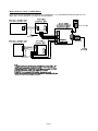
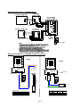
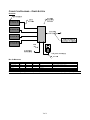
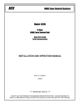
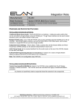
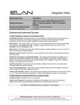
Integration Note
Manufacturer:
RCS
Model Number(s):
TR/TS40, TR/TS16, TR/TS60 Thermostat
Minimum Core Module Version:
4.0, build 1583
Document Revision Date:
2/18/2013
OVERVIEW AND SUPPORTED FEATURES
The RCS TR16 and TR40 are retrofit-able RS-485 communicating thermostats that use a 2-piece installation
method to leverage existing HVAC wiring for easy install. Each thermostat consists of two parts: a wall display
unit, which resembles a typical thermostat; and a HVAC Control unit. The WDU is installed using existing
HVAC wires at the desired location, and connected to the HVAC Unit back box via the existing 4-wire run. All
new wire connections can then be made the HVAC unit without running new wires to each thermostat location.
The TS16 and TS40 are variants of the TR16/TR40 that can be used with an HVAC Zone Controller that adds
independent zone control via the use of associated dampers for improved efficiency and distribution. See RCS
for full details.
Independent TR16/TR40 installs, and installs using the TS16/TS40 with ZCV series zone controllers are
compatible with external RS-485 or RS-232 control from g!, and provide reliable two-way control and feedback.
Note: The TR/TS60 is the replacement for the TR/TS40. All steps and notations in this document referencing
the TR/TS40 apply to the TR/TS60. Setup the TR/TS60 exactly as you would a TR/TS40.
RCS THERMOSTATS SUPPORT THE FOLLOWING FEATURES:
Temperature Control: Temperature control can be managed by schedules tied to house modes or by manual
control based on time (Timed Temporary Hold, Temporary Hold and Permanent Hold).
Mode Control: The climate system can be set to run in the following heating and cooling modes: Heat only,
Cool only, Auto Heat Cool (TR40 only) or Off. In addition, systems that have a fan can be set to run in
Automatic mode or Continuous mode.
History View: The history view shows the inside temperature, outside temperature, unit run and fan run times,
and cooling and heating setpoints.
Schedule Control: Multiple schedules may be set up, and are automatically tied to the house mode.
Zone Control: Multi-zone “Smart Damper/Vent” systems using the RCS ZCV series of zone controllers are
compatible with g!.
Remote Sensors: An Outside Temperature Sensor or sensors that replace the room sensor can be read from
RCS climate systems.
ELAN Home Systems ● 1690 Corporate Circle ● Petaluma, CA 94954 USA
tech support: 800.622.3526 • main: 760.710.0990 • sales: 877.289.3526 • email: [email protected]
©2013 ELAN Home Systems. All rights reserved. ELAN and g! are trademarks of ELAN Home Systems. All other trademarks are the property of their respective owners.
RCS THERMOSTATS DO NOT SUPPORT THE FOLLOWING FEATURES:
Any feature not specifically noted as “supported” is not supported.
Mode Control: Auto Heat Cool is not available for external control on the TR16 thermostats.
Message Features: Message features supported by RCS for display of text based messages on the WDU
readout are not supported in g!
Humidity: No humidity features or sensors are supported with RCS climate systems.
External Sensors: Remote sensors that do not replace the room sensor or provide outside temp are not
supported.
Decimal Temperature Control: g! Core module 5.5 added support for decimal/fractional temperature display.
The RCS Thermostats are not compatible with control using fractional numbers.
Note: The TS16 and TS40 are equivalent models to the TR16 and TR40, sold for use with Zoned Systems.
They do not include the HVAC controller hardware, as this is part of the ZCV Series controller.
INSTALLATION OVERVIEW
RCS Thermostats may be integrated with the Elan g! system either for RS-485 or RS-232 control. 485
Connections may be made to either a RS-485 port on a g! Controller, EdgeBrick, or on the RS-485 port of a
legacy MultiBrick. RS-232 connections may be made directly to the controller or through a variety of other
methods such as EdgeBrick, Moxa, or Global Cache.
CONVENTIONAL SYSTEM WITH 8AH485D OR 485PB RS485 WIRING HUB
1. Run Cat5 or 18/4 cable from the Wall Display Unit location to the Control Unit location for new installs.
Retrofit installs may use existing 4-wire cable.
2. If possible, mount the HVAC Control Units and the Wiring Hub in the same location, as this will reduce
wiring labor and facilitate system debugging.
3. Run Cat5 or 18/4 cable from the Control Units to the Wiring Hub, and run appropriate control cable from
the Control Units to the heating and cooling equipment. Consult the HVAC equipment/RCS documentation
for cabling requirements.
4. Run Cat5 from the Wiring Hub back to the g! system.
5. Mount and connect the Wall Display Unit, the Control Unit and the Wiring Hub electrically using the
diagrams provided.
6. Recheck the wiring at the Wall Display Unit, the Control Unit and the Wiring Hub.
7. Install and power up the thermostats one at a time. Program the thermostats as outlined in the thermostat
programming section, noting the thermostat ID number.
8. Test the thermostat and climate system to ensure that the thermostats correctly turn on the appropriate
heating or cooling equipment, and open or close the appropriate valves / dampers.
9. Connect the g! system to the RCS thermostats electrically. See the wiring diagrams.
10. Configure the g! system for the thermostats and confirm communication between the thermostats and the
g! Controller.
11. Test the system by changing the set points, modes and schedules on the viewer and various thermostats,
confirming that the various components in the system respond as expected.
2 of 11
ZONED SYSTEM USING A ZCV-SERIES ZONE CONTROLLER
1. Run Cat5 or 18/4 cable from the Wall Display Unit location to the Zone Control Unit location for new
installs. Retrofit installs may use existing 4-wire cable.
2. Run appropriate control cable from the Zone Control Unit to the heating and cooling equipment. Consult
the HVAC equipment documentation for cabling requirements.
3. Run Cat5 from the Zone Controller back to the g! system.
4. Mount and connect the Wall Display Unit, the Zone Control Unit and the 485 Converter (if required)
electrically using the diagrams provided.
5. Recheck the wiring at the Wall Display Unit, the Zone Control Unit and the RS485 Converter.
6. Install and power up the thermostats one at a time. Program the thermostats as outlined in the thermostat
programming section, noting the thermostat ID number.
7. Test the thermostat and climate system to ensure that the thermostats correctly turn on the appropriate
heating or cooling equipment, and open or close the appropriate valves / dampers.
8. Connect the g! system to the RCS thermostats electrically. See the wiring diagrams.
9. Configure the g! system for the thermostats and confirm communication between the thermostats and the
g! Controller.
10. Test the system by changing the set points, modes and schedules on the viewer and various thermostats,
confirming that the various components in the system respond as expected.
3 of 11
CONNECTION DIAGRAMS – CONVENTIONAL SYSTEM
OVERVIEW
BILL OF MATERIALS
#
D evice
M anufa cture r
P art N umber
P ro t o co l
C o nnec to r T ype
N o t es
1
Wall Display Unit
RCS
TR16 o r TR40
P roprietary
Terminal Strip
The TR16/TR40 includes the Wall Display Unit and the HVA C Co ntrol unit
2
Cat5 o r 18-4 Cable
Installer
N/A
Vario us
No ne
Cat5 cable is preferred, though 18-4 will wo rk
3
HVA C Contro l Unit
RCS
TR16 o r TR40
P roprietary X RS-485 Terminal Strip
4
18-2 Cable
N/A
N/A
N/A
5
12 VDC P ower Supply
Vario us
(See No te)
N/A
Terminal Strip
Calculate amperage required before purchase. See RCS docs.
6
Wiring Hub
RCS
485P B
RS-485 X RS-232
Terminal Strip/DB 9 Female
Use the 485P B for short wire runs for 1- 2 Thermo stats
6
Wiring Hub
RCS
8A H485D
RS-485 X RS-232
Terminal Strip/Terminal Strip or RJ45 F Star Wire Topo lo gy 8-Channel 485 x 1-channel RS485 o r RS232
The TR16/TR40 includes the Wall Display Unit and the HVA C Co ntrol unit
Terminal Strip
OR
Note: Some wiring configurations may also require HA-CB-307 DB9M-to-RJ45F (straight thru) adapters.
4 of 11
WIRING DIAGRAM 1: DETAIL OF 485PB WIRING
Note: Per RCS Documentation, the 485PB unit is intended for 1 or 2 thermostats with short wiring runs. For
larger jobs, use the 8AH485D: see below for wiring diagrams.
5 of 11
WIRING DIAGRAM 2A: DETAIL OF 8AH485D WIRING
WIRING DIAGRAM 2B: DETAIL OF 8AH485D COMMUNICATION WIRING
RS‐232/RS‐485 Selector Jumpers
RS‐232/RS‐485 Selector Jumpers
RS‐485
RS‐232
RS‐485
Close 1, 2
1: White / Orange
2: Orange
3: White / Green
4: Blue
5: White / Blue
6: Green
7: White / Brown
8: Brown
RS485
V+
G
D+
D‐
RJ45
RS‐232
Close 2, 3
RS485
Custom Terminate
RJ45
7 or 8
6
3
4
5
6
CAT5
RJ45
(Clip Down)
1
8
RS485 Connection
RCS End Function 568 B Color g! End (B)
GND
Blue
7 or 8
4
D+
White/Orange 5
1
DGreen
2
6
(Clip Down)
Cat5 Cable
(EIA 568 Standard ‘B’ Colors)
Cat5 Cable
8AH485D
8
1
Green
White / Orange
Blue
8AH485D
V+
G
D+
D‐
RJ45
6 of 11
8
Pin 568 B
RS232 Connection
RCS End Function 568 B Color
GND
Blue
7 or 8
RX
White/Blue
6
TX
Green
3
To g! RS485
1
RJ45
(Clip Down)
g! End (B)
4
5
6
To g!
RS232
CONNECTION DIAGRAMS – ZONED SYSTEM
OVERVIEW
BILL OF MATERIALS
#
D e v ic e
M a nuf a c t ure r
P a rt N um be r
P ro t o c o l
C o nne c t o r T ype
1
Wall Display Unit
RCS
TS16 o r TS40
P ro prietary
Terminal Strip
2
Cat5 o r 18-4 Cable
Installer
N/A
Vario us
No ne
3
Zo ned HVA C Co ntro ller
RCS
ZCVx
P ro prietary X RS-485 Terminal Strip
4
18-2 Cable
N/A
N/A
N/A
Terminal Strip
5
24VA C P o wer Supply
Vario us
(See No te)
N/A
Terminal Strip
N o tes
Cat5 cable is preferred, tho ugh 18-4 will wo rk
x=number o f zo nes
Calculate amperage required befo re purchase. See RCS do cs.
Note: Some wiring configurations may also require HA-CB-307 DB9M-to-RJ45F (straight thru) adapters.
7 of 11
WIRING DIAGRAM 3: DETAIL OF ZONED HVAC CONTROL SYSTEM
8 of 11
THERMOSTAT PROGRAMMING
Once the thermostats are powered up and running properly, you need to make a few changes to the
thermostat settings to integrate with g!. Other than the changes listed below, follow standard RCS
programming procedures: all TStats and Zone Controllers must be properly configured for standalone
operation prior to integration in g!.
TR16 STANDARD THERMOSTAT SETUP
The changes outlined below assume that you are starting with a factory default thermostat. These changes
then will put the thermostat into a standard g! setup.
Step
Instructions
Comments
1
Press [Mode] and then [Fan] until SU
appears on the display. Release the
buttons and Ad will appear
Places the thermostat into Setup Mode.
2
Press [Up] or [Down] until the desired
Address Number appears.
Sets the Address of the thermostat
3
Do nothing for 3 seconds until the display
Exits the setup mode
Exit the setup mode.
TR40 STANDARD THERMOSTAT SETUP
The changes outlined below assume that you are starting with a factory default thermostat. These changes
then will put the thermostat into a standard g! setup.
Step
Instructions
Comments
1
Press [Menu] (leftmost button) to enter
the Thermostat Menu.
Unit will display the basic menu, with users settings
and schedules.
2
Press and hold the center two buttons
until the Thermostat enters the Installer
Settings.
Unit will display the installer menu with service mode,
network settings etc.
3
Use the [Up] and [Down] arrows to
navigate to Network Settings, then
press the right most button to [Select].
Unit will enter the Network Settings page.
4
Using the center buttons for [+] or [-],
adjust the Network Addr until it reads
the desired network address.
Set all thermostats to a valid, unique address. Typically
it is recommended to increment Thermostats
sequentially (1, 2, 3 etc.)
5
Confirm Network Type is set to RCS
and Autosend is set to Y.
If needed, use the [Up] and [Down] arrows to navigate
and alter settings using the center buttons ([+] or [-]).
Important! Each thermostat must be set to a unique address.
9 of 11
g! CONFIGURATION DETAILS
The following table provides settings used in the g! Configurator when connecting to an RCS thermostat network. Please refer to the Configurator
Reference Guide for more details.
In the table below:
o
“<Select>”
Select the appropriate item from the list (or drop-down) in the Configurator.
o
“<User Defined>”, etc.
Type in the desired name for the item.
o
“<Auto Detect>”, etc.
The system will auto detect this variable.
Devices
Communication Devices
HVAC Units
Variable Name
Setting
Name
Type
Communication Type
Location
Com Port
Protocol
<User Defined> (Default: New Device)
Serial Port
RCS Thermostat Network
<User Defined> (Not Required)
<Select from list>
<Select from list>
Name
Model
Controls Heat
Controls Cooling
Controls Fan
<User Defined>
Generic HVAC Unit
<Select from list>
<Select from list>
<Select from list>
Comments
Elan recommends renaming for clarity
COM1, 2, 3 etc.
Choose RS-232 for RS-232 Control, OR
Choose RS485 Half-Duplex for RS485 Control
Add Thermostats Manually, choose type as appropriate (RCS TR40 Thermostat for TR/TS40 and TR/TS60; RCS TR16 Thermostat for TR/TS16 Thermostats)
Thermostats
Name
Location
Com Device
Thermostat ID
Heating Unit
Cooling Unit
<User Defined>
<User Defined> (Not Required)
<Select> (Default: New Device)
<Select from list>(Default: 1, See Note 1)
<Select from list>
<Select from list>
Should automatically associate with RCS Thermostat Network
Notes:
1. You must enter the correct thermostat ID for each thermostat. IDs must start at 1, and increment sequentially without skipping numbers.
Note: Outside temperature sensor will be auto-detected and appear as an option under Global Options in the Climate tab within a few moments after RCS
TStats are added and communication is established.
10 of 11
COMMON MISTAKES
1. Programming two thermostats with the same address.
2. Incorrect serial type setting. The RCS Thermostat Network Communication Device has a drop down
for RS-232 or RS-485. Set this appropriately: RS-485 connections should be set to RS-485 HalfDuplex, RS-232 connections should be set to RS-232.
11 of 11