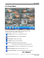
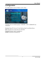
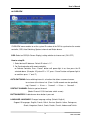
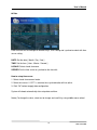
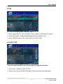
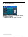
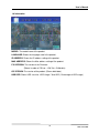
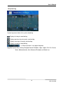
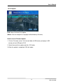
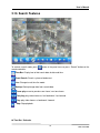
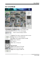
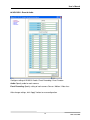
1
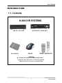
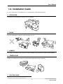
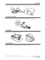
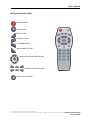
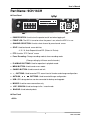
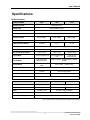
Standalone DVR
LAX Series H.264 DVR
USER’S MANUAL
LAX 912 / LAX 1612
User’s Manual
TABLE OF CONTENTS
CHAPTER 1 INTRODUCTION ...................................................2
1.1.
Contents ....................................................................................................... 3
1.2.
Installation Guide ......................................................................................... 5
1.3.
Part Name : 4CH ........................................................................................... 6
1.4.
Part Name : 9CH/16CH ................................................................................. 8
1.5.
Specifications ............................................................................................. 11
CHAPTER 2 MAIN SYSTEM APPLICATION ...............................12
2.1.
Startup Screen............................................................................................ 13
2.2.
Login........................................................................................................... 14
2.3.
Exit/Log Out ............................................................................................... 15
2.4.
Panel Menu ................................................................................................. 16
2.5
System Configuration ................................................................................. 17
2.6.
Camera Configuration ................................................................................. 22
2.7.
Event Configuration .................................................................................... 28
2.8.
Network Configuration ............................................................................... 33
2.9.
Information Configuration .......................................................................... 38
2.10.
Search Features .......................................................................................... 42
CHAPTER 3 WEB DVR ...........................................................46
3.1.
Login........................................................................................................... 47
3.2.
Live Mode ................................................................................................... 48
3.3.
Search Mode ............................................................................................... 49
3.4.
Setting Mode............................................................................................... 50
WARRANTY………………………………………………………………………55
1
LAX Series DVR
User’s Manual
CHAPTER 1
INTRODUCTION
1.1. Contents .......................................................................................................................... 3
1.2. Installation Guide.................................................................................................. 4
1.3. Part Name : 4CH...................................................................................................... 6
1.4. Part Name : 9CH/16CH.................................................................................... 8
1.5. Specifications ........................................................................................................... 11
2
LAX Series DVR
User’s Manual
INTRODUCTION
1.1. Contents
H.264 DVR SYSTEMS
LAX 412 - 4 Ch. DVR
User’s Manual
LAX 912/1612 - 9/16Ch. DVR
MOUSE
REMOTE CONTROLLER
※ Contents are subjectCAUTION
to change without notice.
Danger of explosion if battery is incorrectly replaced.
Replace only with the same or equivalent type.
3
LAX Series DVR
User’s Manual
1.2. Installation Guide
To ensure the product’s best performance, it is recommended to follow below instructions.
VENTILATION
To prevent from overheating, do not block cover or ventilation.
SHOCK
Place the product where can be free from outer physical shock.
HUMIDITY
Do not place a humidifier near the product as extreme humidity can badly affect the product’s normal operation
TEMPERATURE
Avoid dust, humidity and do not place the product where temperature changes extremely.
ELECTRIC NOISE
4
LAX Series DVR
User’s Manual
Do not place the product near a microwave, Radio or TV which can generate signal noise due to radio frequency.
DIRECT RAY OF LIGHT
Direct ray of light can cause abnormal operation. Keep the product away from direct ray of light
.
VIBRATION
Install the product on even place where no vibration
.
INSTALLATION
The socket-outlet shall be installed near the apparatus and shall be easily accessible.
5
LAX Series DVR
User’s Manual
1.3 Part Name: 4Ch
Front Panel
④③ ②
①
⑤
①
POWER SWITCH: Used to turn the product on/off and when logging off.
②
POWER LED: The LED is turned on when the power is on.
③
NETWORK LED: The LED is on when network is in active.
④
HDD LED: The LED is on when HDD is in active.
⑤
USB: USB Flash drive can be connected to backup and firmware upgrade.
(Notice: Mouse connection is not available on Front USB)
Rear Panel
⑥
④
⑧
③
⑤
①
②
⑨
⑩
⑦
①
LAN
②
MOUSE
③
VGA
④
VIDEO INPUT
⑤
SPOT OUTPUT
⑥
MONITOR OUTPUT
⑦
AUDIO OUTPUT
⑧
AUDIO INPUT
⑨
RS485, SENSOR INPUT, RELAY OUTPUT
⑩
POWER INPUT
6
LAX Series DVR
User’s Manual
Remote Controller (4CH)
POWER BUTTON
MUTE BUTTON
MENU BUTTON
CANCEL BUTTON
LIVE MODE BUTTON
SEARCH MODE BUTTON
CONFIGURATION CONTROL BUTTON
PLAYBACK CONTROL BUTTON
BACKUP MENU BUTTON
7
LAX Series DVR
User’s Manual
Part Name: 9CH/16CH
Front Panel
⑤⑥
③
⑧⑩
④
①
⑪
⑭
⑮
⑦
②
⑨ ⑫
⑬
①
POWER SWITCH: Used to turn the product on/off and when logging off.
②
FRONT LED: The LED is turned on when the power is on, when the HDD is in use.
③
CHANNEL SELECTION: Used to select channel by one channel screen.
④
SPLIT: Used to channel screen division;
4 / 9 / 16, Auto Sequential and PIP (Picture In Picture)
⑤
PTZ: Used for “PTZ Control” screen
⑥
Force Recording: Change recording mode to force recording mode
(Change setting by full frame on all channels.)
⑦
PLAYBACK BUTTONS: Used for operation in playback mode.
⑧
MENU BUTTON: Used to enter menu mode.
⑨
CANCEL BUTTON: Used to cancel and exit.
⑩
+ , - BUTTONS: Used to control PTZ, zoom in/out of time bar and change configurations.
⑪
AUTO/OK ,
⑫
USB: USB storage devices can be connected for backup and upgrade.
⑬
MOUSE: Used for mouse connection only.
⑭
LIVE / SEARCH: Used to change to live / search mode
⑮
BACKUP: Used to backup data.
< > ︿ ﹀ BUTTONS: Used to control/change configuration.
Rear Panel
<9CH>
8
LAX Series DVR
User’s Manual
①
⑪
②
③
<16CH>
①
⑧
⑨
⑩
⑦
④⑤
⑬
⑥
②
⑦
①
POWER
③
⑫
⑪
③
④ ⑤
⑫
⑥
⑧
⑨
⑩
②
VIDEO INPUT
VIDEO LOOP OUTPUT
④
MULTIPLEX OUTPUT
⑤
SPOT OUTPUT
⑥
AUDIO INPUT ( 4 CHANNEL)
⑦
AUDIO OUTPUT
⑧
LAN
⑨
RS232
⑩
VGA
⑪
SENSOR INPUT
⑫
RS485
⑬
RELAY OUTPUT
⑬
9
LAX Series DVR
User’s Manual
Remote Controller (9CH / 16CH)
POWER BUTTON
FORCE RECORDING BUTTON
ZOOM IN / CHANGE BUTTON
ZOOM OUT / CHANGE BUTTON
MENU BUTTON
CANCEL BUTTON
LIVE MODE BUTTON
SEARCH MODE BUTTON
CONFIGURATION CONTROL BUTTON
PLAYBACK CONTROL BUTTON
PTZ CONTAROL BUTTON
SPLIT SCREEN MODE BUTTON
SWITCH SCREEN MODE BUTTON
BACKUP MENU BUTTON
10
LAX Series DVR
User’s Manual
Specifications
Specifications
SPECIFICATIONS
4CH
9CH
Operating System
Embedded Linux
Compression
Multiplexer Functionality
H.264 Hardware Codec
Triplex (Live, Record, Playback, Network at the same time)
Recording Resolution
Displaying Speed
D1, Half D1, CIF
PAL 100fps,
NTSC 120fps
Recording Speed
Video Input/Loop Output
Video Output
16CH
PAL 225fps,
NTSC 270fps
PAL 400fps,
NTSC 480fps
PAL 100fps, NTSC 120fps @ CIF resolution
4 / 0 BNC
9/9
16 / 16
2 BNC Composite (Spot, and Monitor), 1 VGA
Audio Input/ Output(RCA cable)
1 line / 1 line
Sensor Input/Relay Output
4 line / 1 line
8 line / 4 line
16 line / 4 line
Display Mode
1/4 and sequential, PIP
1/4/9 and Sequential,
PIP
1/4/9/16 and
Sequential, PIP
Backup Media
USB Flash Drive,
Network Backup
USB Flash Drive, DVD/W(Option), Network
Backup
Storage Media
Max 1 HDD, Front 1
USB
Max 3 HDDs, 1 USB memory
Recording Mode Method
System Control
Communication Port
Network
Dimension
Size(mm)
4 line / 1 line
Motion detection and Sensor
Mouse and Remote
controller
Mouse, Remote Controller
and Front Key Button
RS-485
RS232C, RS485
LAN(Ethernet RJ-45, 10/100 base), DDNS, TCP-IP
4CH
9CH
320(W)x255(D)x60(H)
Weight
3Kg
Power
12V DC 3.33A
430(W)x440(D)x88(H)
7.5Kg
Operating Temperature
16CH
8Kg
AC 100V ~ 240V, 50/60Hz
0°C~40°C
Operating Humidity
10~80% RH
* The contents of this specification may change without notice.
11
LAX Series DVR
User’s Manual
CHAPTER 2
MAIN SYSTEM APPLICATION
2.1. Startup Screen. ........................................................................................................ 13
2.2. Login. ................................................................................................................................ 14
2.3. Exit/Log Out ................................................................................................................ 15
2.4. Panel Menu .................................................................................................................
16
2.5. System Configuration .......................................................................................... 16
2.6. Camera Configuration. ........................................................................................ 22
2.7. Event Configuration............................................................................................... 28
2.8. Network Configuration ........................................................................................ 33
2.9. Information Configuration................................................................................ 37
2.10. Search Features. ...................................................................................................... 41
12
LAX Series DVR
User’s Manual
2.1. Startup Screen
To start DVR system, press power switch on front panel or power button on remote controller.
As DVR starts, the system will detect NTSC/PAL automatically.
In a few seconds, live images would be displayed.
The above screen will appear as DVR system starts when booting is finished.
This may take up to 1 minute to check the system status.
13
LAX Series DVR
User’s Manual
2.2. Login
The factory default values for User and Password are “admin” and no password.
How to login DVR system:
1. Use
to change the user level.
2. Insert Password by click input area. Max 5 numeric characters are required.
(You will see the numeric buttons to select)
3. Click
to execute HR04 system.
To specify password to users, certain configurations are required
(Menu/System/Password).
Only “admin” will have access right to the setup menu.
User Authority:
There are 5 total users: admin, anonymous, user1, user2 and user3
Admin: Access right to Live, Search, Setup and Shutdown
User1, User2, User3: Access right to Live and Search
Anonymous: Access right to live only
14
LAX Series DVR
User’s Manual
2.3. Exit/Log Out
How to end DVR system:
1. Press power switch on front panel or power button on remote controller.
2. Select “Exit” and input password and then click “OK” button.
(To logout DVR system, select “Logout” and input password and click “OK” button.)
15
LAX Series DVR
User’s Manual
2.4. Panel Menu
To activate the panel menu as above picture, just right click on screen.
To hide “panel menu”, right click on screen again.
Exit button: Log out user or shuts down DVR system.
System Setup button: Setup system configuration.
Search button: Displays search mode.
PTZ button: Displays PTZ control button.
PIP button: Enable PIP (Picture in Picture) function.
On PIP mode, click PIP button to change channel in PIP.
Full screen button: Enlarges the selected camera as full screen view.
Split screen button: Shows split screen view (4 / 9 / 16).
Channel switch mode: Full screen mode with the cameras switching.
2.5. System
16
LAX Series DVR
User’s Manual
Configuration
This chapter explains menu for configure system settings.
“SYSTEM” consists of 4 different groups; “OVERVIEW”, “DATE”, “PASSWORD” and
“INITIALIZE”
Overview: Setup OSD, System ID, Auto Switching, Spot Out and Button Buzzer
Date: Setup Date, time, locale and server information.
Password: Setup password for specified user.
Initialize: Initialize log, setting and HDD.
17
LAX Series DVR
User’s Manual
OVERVIEW
OVERVIEW menu enables to set the system ID number of the DVR to synchronize the remote
controller, OSD, Auto-Switching, Spot out channel and Button buzzer.
OSD: Select an OSD(On Screen Display) setting whether to show or not. (ON / OFF)
How to setup ID:
1. Select desired ID between. Default ID value is “11”.
2. For Synchronization with remote controller,
on Remote Controller, Press “Cancel” button until power light is on, then press the ID
selected above. (Example: If System ID is “12”, press “Cancel” button until power light is
on and then press “1” and “2”)
AUTO-SWITCHING: Auto-switching interval is a function that allows a camera to move
to next one at the interval set. (From 1 to 30 seconds can be specified.)
e.g.) Camera1
→
10 sec.
→
Camera2
→
10 sec.
→
Camera3 …
SPOTOUT CHANNEL: Select a spot out channel.
(Mode: Channel 1/2/3/4 and auto switch screen)
BUTTON BUZZER: Enable buzzer when button is pressed.
LANGUAGE: LANGUAGE: Changes language setting. (Default: English)
Support 15 languages: English, French, Polish, Russian, Spanish, Italian, Portuguese,
Greek, Hungarian, Danish, Czech, Deutch, Finnish, Hebrew and Turkish.
18
LAX Series DVR
User’s Manual
Date
Date and time can be changed in different ways, User setting and synchronize clock with time
server setting.
DATE: Set the date. [ Month / Day / Year ]
TIME: Set the time. [ Hour : Minute : Second ]
LOCALE: Select a local time zone.
SERVER: Set the time server to synchronize the time with.
How to setup time server:
1. Select a local time zone on locale.
2. Select time server. If “OFF” is selected, time synchronization will not active.
3. Click “OK” button to apply date configuration.
System will reboot automatically after setup date and time.
Notice) To change the value, select text to change and scroll it by using middle mouse wheel.
19
LAX Series DVR
User’s Manual
Password
SELECTION: Select the user to change the password.
(admin / anonymous / user1 / user2 / user3 )
NEW: Enter a new password. (Max 8 numeric characters are available)
CONFIRM: Enter the new password again for confirmation.
20
LAX Series DVR
User’s Manual
Initialize
LOG: Select “ON” to initialize log data.
SETTING: Select “ON” to initialize setting of system configuration.
HDD: Select “ON” to initialize HDD data.
FACTORY: Select “ON” to revert to factory default.
Configure each initialize setting and press “OK” button to apply initialization.
21
LAX Series DVR
User’s Manual
2.6. Camera Configuration
This chapter explains menu for configure camera settings.
“CAMERA” consists of 4 different groups; “CHANNEL“, “COLOR”, “PTZ” and “AUDIO”
CHANNEL: Channel Video/Audio Setup menu to set ON/OFF video and audio.
COLOR: Color Adjust menu to adjust brightness, contrast, saturation and hue value.
PTZ: PTZ configuration menu to setting PTZ device.
AUDIO: Audio configuration menu to assign. (HR09/16 Only)
22
LAX Series DVR
User’s Manual
Channel
TOTAL FRAME: shows current frame / total max frame when channel configuration is set.
There are two categories to setting channel configuration: COMMON / INDIVIDUAL
[COMMON]: Setting affects all camera channels.
CAMERA: Displays camera number to change settings.
Use
buttons to move to the next channel.
AUDIO: Select audio recording condition of all cameras. ( ON / OFF )
(Only 4CH DVR supports this option: 1 CH audio)
RESOLUTION: Select recording resolution of all cameras. ( D1 / Half D1 / CIF )
D1: Max 30fps(NTSC) / 25fps(PAL)
Half D1: Max 60fps(NTSC) / 50fps(PAL)
CIF: Max 120fps(NTSC) / 100fps(PAL)
DE-INTERLACE: Select interlace image process condition of all cameras ( ON / OFF )
[INDIVIDUAL]: Setting affects each camera channels.
FRAME: Configure frame setting for each cameras
(Notice!: Sum of frames cannot exceed max total frame.
Frame cannot exceed value of event frame. )
EVENT FRAME: Configure frame setting for each cameras when event occurs.
(Notice!: Sum of frames cannot exceed max total frame.
QUALITY: Select level of video image quality of all cameras.
Very High, High, Normal, Low, Very Low, Network
(“Network” value get lowest image quality but frequent remote view.)
23
LAX Series DVR
User’s Manual
Color
CAMERA: Select a camera number to adjust the color settings.
BRIGHTNESS: Adjust the brightness of the camera image using the
CONTRAST: Adjust the contrast of the camera image using the
buttons.
buttons.
SATURATION: Adjust the color saturation of the camera image using the
HUE: Adjust the hue value of the camera image using the
buttons.
buttons.
: Changes all values back to default values.
:
Apply specified values to all cameras.
:
Press “OK” button to save changed color settings.
:
Press “CNCL” button to cancel the changed color settings.
24
LAX Series DVR
User’s Manual
PTZ
CAMERA: Select a camera number to configure PTZ setting.
DEVICE NAME: Select PTZ controller to configure by using the
buttons.
DEVICE ID: Set PTZ ID by using the
FLOW CNTL: Set Flow Control value by using the
buttons.
BPS: Set BPS(Bit per second) value of PTZ by using the
PAR: Set Parity of PTZ by using the
buttons.
buttons.
buttons.
STOP BIT: Set stop bit of PTZ by using the
buttons.
DATA BIT: Set data bit of PTZ by using the
buttons.
(Notice!: It is not recommended to change Flow Control, Parity, Stop Bit, Data Bit)
Please refer to PTZ controller manual from PTZ manufacturer to get more information about
PTZ setting.
How to Control PTZ
1. Select camera to control PTZ.
2. Click PTZ button (
or Press PTZ button (
) on the panel menu to open PTZ control menu.
) on front key or remote controller.
25
LAX Series DVR
User’s Manual
PTZ Control Menu
CA: Select PTZ camera by pressing
buttons.
SP: Specify PTZ control speed by pressing
buttons.
Press arrow buttons to control direction of PTZ camera.
AUTO: Press “AUTO” button to move PTZ direction to auto position.
(Notice!: If camera doesn’t support “AUTO” mode, it will not work.
Auto position can’t be specified by DVR. It can be specified in PTZ camera.)
ZOOM: Control camera zoom in / out ( - / + )
FOCU: Adjust camera focus in / out ( - / + )
IRIS: Adjust camera Iris
EXIT: Press EXIT button to finish PTZ control
26
LAX Series DVR
User’s Manual
AUDIO
This Audio menu is available on 9CH/16CH DVR only.
AUDIO 1/2/3/4: Select a camera number to set audio
27
LAX Series DVR
User’s Manual
2.7. Event Configuration
“Event” consists of 3 different groups; “Sensor”, “Motion” and “Video Loss”
On this menu, devices can be set to respond to different events.
SENSOR: Set sensor event configuration.
(Set sensor mode, sensor type, alarm, alert and duration.)
MOTION: Set motion event configuration.
(Set motion mode, alarm, alert and duration.)
VIDEO LOSS: Set video loss event configuration.
(Set video loss settings, alarm, alert and duration.)
28
LAX Series DVR
User’s Manual
Sensor
SENSOR: The sensor number to change settings.
Use
button to move to next sensor.
MODE: Set sensor mode.
(ON / OFF, if mode is OFF, alarm and alert will not be activated.)
TYPE: Set sensor type. (N.C: Normal Close Type / N.O: Normal Open Type)
ALARM: Set alarm settings.
(ON / OFF, only effective when sensor mode is ON)
!(4CH DVR supports only 1 alarm.)
ALERT: Alert is the beep inside the system that sounds in the case of event.
Set internal alert settings. (ON / OFF)
DURATION: Set duration value of beep sound when alert occurs. (1~10)
Changing value affects to all events.
29
LAX Series DVR
User’s Manual
Motion
Motion is a function that enables DVR system to detect every movements or motions by
comparing a frame with its previous frame.
CHANNEL: The channel number to change motion settings.
Use
button to move to next channel.
MODE: Set motion detection settings.
(ON / OFF, if mode is OFF, alarm and alert will not be activated.)
MOTION ZONE: click
button to set motion detection area.
Refer to next page to detailed instruction.
SENSITIVITY: Set sensitivity of motion detection (Low / Normal / High)
ALARM: Set alarm settings.
(ON / OFF, only effective when mode is ON)
!(4CH
DVR supports only 1 alarm.)
ALERT: Set alert settings. (ON / OFF, only effective when mode is ON)
DURATION: Set duration value of beep sound when alert occurs. (1~10)
Changing value affects to all events.
30
LAX Series DVR
User’s Manual
Motion Zone
How to select motion detection zone:
1. Use mouse to specify detection zone.
2. Drag & Drop will change the property of area.(Selected / Unselected)
MODE: Shows current activation (Move / Selection / Unselection)
Clear Screen area: Selected motion detection zone.
Green Screen area: Unselected motion detection zone.
3. Right click to show the menu to select / unselect / save.
SELECT ALL: Select whole area as motion detection zone.
UNSELECT ALL: Unselect whole area as motion detection zone.
SAVE: Save current selection and go out from motion zone screen.
EXIT: cancel current selection and go out from motion zone screen.
31
LAX Series DVR
User’s Manual
Video Loss
CHANNEL: The channel number to change video signal settings.
Use
button to move to next channel.
MODE: Set video signal settings.
(ON / OFF, if mode is OFF, alarm and alert will not active.)
ALARM: Set alarm settings.
( ON / OFF, only effective when mode is ON )
!( 4CH DVR supports only 1 alarm )
ALERT: Set Alert Settings.
( ON / OFF, only effective when mode is ON )
DURATION: Set duration value of beep sound when alert occurs. (1~10)
Changing value affects to all events.
32
LAX Series DVR
User’s Manual
2.8. Network Configuration
This chapter explains menu for configure network settings.
TCP/IP: Setup TCP / IP settings.
(Sets IP type, Bandwidth, IP address, Gateway, Subnet Mask,)
PORT: Setup TCP / IP port to access by web and application.
(Sets Web, Playback and live port)
DDNS: Setup Dynamic DNS server settings. (Sets DDNS mode, port, domain name and
interval time)
CMS: Setup CMS server settings (Sets CMS mode, IP address and port)
EVENT FILTER: Specify events to send to CMS server.
Notice!: CMS connection is supported by 4CH DVR only.
9CH/16CH DVR will support CMS on the future release.
33
LAX Series DVR
User’s Manual
TCP/IP
CONFIG: Set the IP type. (DHCP IP / STATIC IP)
BANDWIDTH: Set the network bandwidth. (AUTO / 10Mbps / 100Mbps)
In most cases, AUTO is recommended to set.
“AUTO’ mode detects bandwidth of network connection automatically.
IP ADDRESS: Set the IP address on “Static IP mode”.
GATEWAY: Set the gateway address on “Static IP mode”.
SUBNET MASK: Set the subnet mask address on “Static IP mode”.
DNS: Set the DNS address on “Static IP mode”.
Notice!: If CONFIG is selected as “DHCP IP”, “IP Address”, “Gateway”, “Subnet Mask” and
“DNS” will be inactive.
34
LAX Series DVR
User’s Manual
PORT
WEB: Set the web(HTTP) port to access through web browser. (Default: 80)
PLAYBACK: Set the playback port to access playback video through client software.
(Default: 9091)
LIVE: Set the live port to access live video through client software. (Default: 9092)
35
LAX Series DVR
User’s Manual
DDNS
DDNS is a service allowing a dynamic IP address to have a static domain name, so users can
easily reach the IP address regardless of IP change.
MODE: Set the DDNS server mode as ON to use DNS server. (ON/OFF)
SERVER: Display address of DDNS server (www.dvrdns.net)
PORT: Default value 65500 is recommended to set.
DOMAIN: Once you registered an ID onto DNS Server, input ID.
INTERVAL: Select a proper time interval (1~60) so DVR system communicates with the DDNS
server to brings IP address at the interval set.
How to register domain name to DDNS server:
1. Access” www.dvrdns.net”.
2. Select language as “English”.
3. Click link of “Registering New Domain”.
4. Input domain name and click “Register” button”.
5. Click link of “Updating IP address”.
6. Input IP Address of DVR and click “Update” button.
7. Specify DDNS setting in the DDNS menu of DVR.
36
LAX Series DVR
User’s Manual
CMS
1. In DVR system, go to ‘Menu > Network > CMS’.
2. Switch configurations as “ON” and specify server IP address. (CMS Server IP address)
3. Default Port number is 9100 (Recommended not to modify default value).
4. Click [OK] button and exit menu to continue to event filter setting.
EVENT FILTER
To receive events from DVR, event filter would be configured in the menu.
1. Go to ‘Menu > Network > EVENT FILTER’
2. Choose events to send and click [OK] button and exit menu to save configurations.
37
LAX Series DVR
User’s Manual
2.9. Information Configuration
This chapter explains menu for configure system information and firmware update.
INFORMATION: Displays product information such as model name, IP address and etc.
SYSTEM LOG: Displays system log data.
F / W UPDATE: Running Firmware update is possible in “F / W UPDATE” menu.
38
LAX Series DVR
User’s Manual
Information
MODEL: The model name of the product.
LANGUAGE: Shows the language used in the product.
IP ADDRESS: Shows the IP address setting of the product.
MAC ADDRESS: Shows the Mac address setting of the product.
F/W VERSION: The version of the Firmware.
(Shows in order of F/W ver – H/W Ver – Build date)
OS VERSION: The version of the product. (Shows build date)
HDD SIZE: Shows HDD size info. :HDD Usage / Total HDD ( Percentage of HDD usage )
39
LAX Series DVR
User’s Manual
System Log
System Log menu shows all of system related log.
: Displays first day of searched log.
: Displays previous day of currently searched log.
: Displays next day of currently searched log.
: Displays last day of searched log.
- / +: Move to previous / next page of log data.
Log List: System Start, Setting Changed, Normal Shutdown, Login, Logout, Disk Full, Sensor,
Alarm, Motion detection, Alert, Abnormal Shutdown and Video Loss.
40
LAX Series DVR
User’s Manual
F/W Update
FILE: Select Firmware file to update.
(Notice: You can recognize its language and build date by file name)
How to execute Firmware Update
1. Put new “Firmware version” file into root folder of USB memory and plug in USB
memory to front USB port of DVR.
2. Select firmware file to update and click “OK” button.
3. When the update is completed, DVR will reboot.
41
LAX Series DVR
User’s Manual
2.10. Search Features
To activate search mode, press
remote controller.
button in the panel menu or press “Search” button on the
Time Bar: Display bar to find search data of date and time.
Event Search: Search system related event.
Live: Change to real time live mode.
Backup: Backup image data from saved video.
Frame play: move to previous one frame / next one frame.
Fast play: play video frames as fast backward / fast forward.
Play: play video frames as backward / forward.
Stop: Stop playback.
Time Bar / Calendar
42
LAX Series DVR
User’s Manual
Time Bar: Select time and then click “OK” button to continue search.
Calendar: Select date and then click “OK” button for return to “Time Bar.”
Time Search Steps:
1. Press
button to open Time Bar.
2. Click
button to open calendar: Select date.
3. Return to Time Bar and select hour and minute to search.
4. Click “OK” button to continue search
Event Search
43
LAX Series DVR
User’s Manual
CAMERA: Select a camera to search events.
(CAMERA1 / CAMERA2 / CAMERA3 / CAMERA4 / CAMERA ALL)
Event list: Shows Motion / Sensor / Video Loss events.
44
LAX Series DVR
User’s Manual
Backup
TARGET: Shows backup device information.
CAMERA: Selects camera to backup.
START RECORD: Shows start time of recorded data.
END RECORD: Shows end time of recorded data.
START BACKUP: Set the start time of backup data.
END BACKUP: Set the end time of backup data.
Backup Steps:
1. Set the start time and end time of backup data.
2. Click “OK” to start backup procedure.
3. When backup procedure begins, data size calculation and backup data saving will be
executed automatically.
(Notice: If free size of USB drive is not enough to save in, backup procedure will be cancelled.)
45
LAX Series DVR
User’s Manual
CHAPTER 3
WEB DVR
3.1. Login .................................................................................................................................. 46
3.2. Live Mode ..................................................................................................................... 47
3.3. Search Mode .............................................................................................................. 48
3.4. Setting Mode ............................................................................................................. 49
46
LAX Series DVR
User’s Manual
Menu may change for enhanced performance without notice.
3.1. Login
1. Type in an IP address of DVR server by internet explorer.
2. Install ActiveX control first to get image.
3. Input User ID and password and then Log in to control mode of Web DVR.
Authority of User
Admin: have all rights; Live, Search and Setting is available
(Multiple accesses are not allowed)
User1, User2, User3: have rights; Live, Search is available
(Multiple accesses are not allowed)
Anonymous: Only live view is available
47
LAX Series DVR
User’s Manual
3.2. Live Mode
:
Select a display mode.
(Full Screen Display / 1 / 4 / 9 / 16 CH Display)
: Select a camera to display or control.
Snapshot: Click to take a snapshot from the live screen.
Settings: Click to set DVR configuration.
Use Audio: Click to enable or disable live audio.
Zoom: Zoom in, Zoom out
Iris: Control iris
Focus: Focus in, Focus out
Pan/Tilt Control
Speed: set the speed of PTZ control
Search: Click to load search mode
Logout: Click to logout of WEB DVR
48
LAX Series DVR
User’s Manual
3.3 Search Mode
Save: Click to saves data to PC (AVI, BMP and JPEG format)
Date/time: click to open search window to select date and time.
Use Audio: tick to enable audio.
Playback Control Button:
(Play Backward, Play Forward, Fast Backward, Fast Forward, Stop)
Live: Click to loads live view mode
Logout: Click to logout of Web DVR
49
LAX Series DVR
User’s Manual
3.4 Setting Mode
Click
button to open Settings configuration menu.
(Notice!: Only admin user can access setting mode on web client software.)
Setting menu may differs between HR04 and HR09/16
4CH - Recording
Configure recording setting of HR04 Common / Recording / Event Recording
Common: Setting affects all cameras of DVR.
Recording: Specify setting of each camera: Frames / Event Frames / Quality
Event Recording: Specify setting of each camera: Sensor / Motion / Video Loss
After change settings, click “Apply” button to save configuration.
50
LAX Series DVR
User’s Manual
9CH/16CH – Set Frame
Configure frame setting of HR 09/16: Resolution / Set Frame
Resolution: Specify resolution and De-Interlace mode.
Set Frame: Specify setting of each camera: Frames / Event Frames / Quality
After change settings, click “Apply” button to save configuration.
51
LAX Series DVR
User’s Manual
9CH/16CH - Event & Audio
Configure setting of HR 09/16: Audio / Event Recording / Event Duration
Audio: Specify audio for each camera
Event Recording: Specify setting of each camera: Sensor / Motion / Video Loss
After change settings, click “Apply” button to save configuration.
52
LAX Series DVR
User’s Manual
4CH/9CH/16CH – Network
Configure Network setting of HR System: TCP/IP / PORT / DDNS
TCP/IP: Shows current TCP/IP Setting
PORT: Specify ports of web and search/login
DDNS: Specify DDNS setting
After change settings, click “Apply” button to save configuration.
53
LAX Series DVR
User’s Manual
4CH/9CH/16CH – Information
Display DVR System information
Show Model name, Language, IP Address, Mac Address, Firmware,
OS Version and HDD Usage.
Warranty Statement
Products manufactured by Eastman Telebell International Inc. (“Eastman Security”) come with limited 18-month warranty for
PC Based and Embedded DVRs. Eastman Security warrants these products to be free from defects in material and
54
LAX Series DVR
User’s Manual
workmanship under normal use and service for a period of 18 month from the time of purchase. All LCD DVR Combo
systems come with limited 12-month warranty. Any other items such as DVR Capture Cards & peripherals, CRT/LCD/Plasma
monitors, cameras and others come with limited 12-month warranty. A purchase receipt or other proof of date of original
purchase will be required prior to providing warranty services. All PC Based and Embedded DVR products come with 1
year replacement warranty from the date of purchase. The warranty does not cover damages occurring from shipment,
failures resulting from accident, misuse, neglect, mishandling, faulty installation, improper operation or maintenance,
alteration, power line surge, improper voltage supply, lightning damage, modification or repair not made or authorized by
Eastman Security, damage caused by additions of any kind, deletions and/or services received from any other person other
than an Eastman Security certified technician. Customer assumes all liability arising from loss of data on the hard drive due
to hard drive failure for any reason whatsoever. Warranty does not cover damages caused by war, riot, and/or act of God.
EASTMAN SECURITY is not responsible for computer viruses. Customer shall install Anti Virus programs at its own risk.
THIS WARRANTY SET FORTH ABOVE IS EXCLUSIVE AND IN LIEU OF ALL OTHER WARRANTIES, WHETHER ORAL OR
WRITTEN, EXPRESSED OR IMPLIED.
EASTMAN SECURITY SPECIFICALLY DISCLAIMS ANY AND ALL IMPLIED
WARRANTIES, INCLUDING BUT NOT LIMITED TO WARRANTIES OF MERCHANTABILITY, AND FITNESS FOR A
PARTICULAR PURPOSE AND AGAINST INFRINGEMENT. EASTMAN SECURITY IS NOT RESPONSIBLE FOR SPECIAL,
INCIDENTAL, DIRECT, INDIRECT OR CONSEQUENTIAL DAMAGES RESULTING FROM ANY BREACH OF WARRANTY,
OR UNDER ANY LEGAL THEORY INCLUDING BUT NOT LIMITED TO LOSS OF DATA, DOWNTIME, GOODWILL, DAMAGE
OR REPLACEMENT OF EQUIPMENT AND PROPERTY, AND COSTS OF RECOVERING PROGRAMMING OR
REPRODUCING ANY PROGRAM OR DATA STORED IN OR USED WITH DISK DRIVES IN THE PRODUCT.
Limited Liability
Eastman Telebell International Inc. (“Eastman Security”) assumes no risk and shall not be liable for any damage and
/or loss resulting from the specific applications made of this product. Eastman Security’s liability shall not exceed the
price paid by the purchaser for such product. In no event shall Eastman Security be responsible for any direct,
indirect, special, incidental or consequential damages including the loss of use, loss of profit and claims of third parties
however caused, whether by the negligence of Eastman Security or otherwise in connection with the purchase,
installation, operation, or failure of this product.
Warranty Services /Out of Warranty Repairs
To obtain warranty services and/or “out of warranty” repair services:
1.
2.
3.
4.
5.
6.
Request RMA/RA number from Eastman Security by phone: 626.336.0065.
Complete RMA/RA Request Form and fax to: 626.336.1939.
RMA/RA number shall be issued within 24 hours upon receipt of completed form.
Mark all returning items with the RMA/RA number clearly on the box. All products must be shipped to
Eastman Security within 14 business days of the RMA/RA number issue date. Packaging must be equal to or
better than original packaging. Eastman Security reserves the right to reject inadequately packaged items.
Customer must prepay shipping and insurance charges for RMA/RA items to Eastman.
Ship to: Eastman Telebell International Inc. 15358 E. Valley Blvd., City of Industry, CA 91746 / Mark RMA/RA#
CORPORATE
Eastman Telebell International Inc.
dba EASTMAN SECURITY
15358 E. Valley Blvd., City of Industry, CA 91746
Tel: 626.336.0065 | Fax: 626.336.1939 | Toll Free: 1.800.526.7777
Email: [email protected] | [email protected]
55
LAX Series DVR