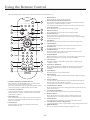
1
CINEMA 6
192 kHz / 24 Bit
Digital to Analog Converter
Surround Sound Processor Preamplifier
NOTE:
Before installing your new surround sound processor, please read this manual carefully, as it
will inform you of the specifications, proper installation procedures and operation procedures.
Also included in this manual are guidelines on how to properly service and care for your new
surround sound processor. Thank you for buying a Cary Audio Design CINEMA 6 surround
sound processor.
HDCD , High Definition Compatible Digital and Pacific Microsonics are either registered trademarks or
trademarks of Pacific Microsonics, Inc. in the United States and /or other countries.
HDCD system manufactured under license from Pacific Microsonics, Inc.
This product is covered by one or more of the following :
Country
Patent No.
5,479,168 5,638,074 5,640,161 5,808,574
United States
5,838,274 5,854,600 5,864,311 5,872,531
669,114
Australia
Other patents pending.
Notice Important Safety Information
CAUTION: To reduce the risk of electric shock, do not remove the
cover No user service-able parts inside. Refer to qualified personnel.
WARNING: To reduce the risk of fire or electric shock, do not expose
this appliance to rain or moisture.
The lightning flash with arrowhead symbol within an equilateral triangle is intended to alert the user to the
presence of uninsulated dangerous voltage within the products enclosure, that may be of sufficient magnitude to
constitute a risk of electric shock to persons.
The exclamation point within an equilateral triangle is intended to alert the user of the presence of important
operating and maintenance (servicing) instructions in the literature accompanying the appliance.
1. Read All Instructions: All the safety and operating instructions of your Cary Audio equipment should be
read before power is applied to the equipment.
2. Retain Owner's Manual: These safety and operating instructions should be retained for future reference.
3. Heed Warning: All warnings on the unit and in the operating instructions should be adhered to,
4. Follow Instructions: All operating and use instructions should be followed.
5. Cleaning: Unplug the unit from the wall outlet before cleaning. The unit should be cleaned only as recommended
by the manufacturer .
6. Attachments: Do not use attachments not recommended by the unit manufacturer as they may cause hazards.
7. Water and Moisture: Do not use the unit near water-for example, near a bath tub, wash bowl, kitchen sink, or
laundry tub; in a wet basement; or near a swimming pool.
8. Accessories: Do not place the unit on an unstable cart, stand, tripod, bracket, or table. The unit may fall, causing
serious injury to a child or adult, and serious damage to Any mounting of the unit should follow the
manufacturer's instructions, and should use a mounting accessory recommended by the manufacturer
9. Ventilation: Slots and openings in the cabinet are provided for ventilation and to ensure reliable operation of the unit and
to protect it from overheating, and these openings must not be blocked or covered. The openings should never be
blocked by placing the unit on a bed, sofa, rug, or other similar surface. The unit should not be placed in a built-in
installation such as a bookcase or rack unless proper ventilation is provided. There should be free space of at least
6 inches (16cm) and an opening behind the unit,
10. Grounding or Polarization: The unit may be equipped with a polarized alternating current line plug (a plug having one
blade wider than the other). This plug will fit into the power outlet only one way. This is a safety feature. If you cannot
insert the plug fully into the outlet, try reversing the plug. If the plug should still fail to fit, contact a licensed electrician to
replace your obsolete outlet. Do not defeat the safety purpose of the polarized plug.
11. Power Sources: The unit should be operated only from the type of power source indicated on the marking label. If you
are not sure of the type of power supplied to your home, consult your unit dealer or local power company
.
12. Power-Cord Protection: Power-supply cords should be routed so that they are unlikely to be walked on or pinched
by items placed upon or against them, paying particular attention to cords where they enter a plug, or a convenience
receptacle, and the point where they exit from the unit.
13.Outdoor Antenna Grounding: If an outside antenna or cable system is connected to the unit, be sure the antenna or
cable system is grounded so as to provide some protection against voltage surges and built-up static charges.Article 810
of the National Electrical Code, ANSI/NFPA 70, provides information regarding proper grounding of the mast and
supporting structure, grounding of the lead-in wire to an Antenna-discharge unit, size of grounding conductors,
location of antenna-discharge unit, connection to grounding electrodes, and requirements for the grounding electrode,
14.Lightning: For added protection for the unit during a lightning storm, or when it is left unattended and unused for
long periods of time, unplug it from the wall outlet and disconnect the antenna or cable system. This will prevent
damage to the unit due to lightning and power -line surges.
15. Power Lines: An outside antenna system should not be located in the vicinity of overhead power lines or other
electric light or power circuits ,or where it can fall into such power lines or circuits . When installing an outside antenna
system, take extreme care to keep from touching such power lines or circuits as contact with them might be fatal.
16. Overloading: Do not Overload wall outlets, extension cords, or integral convenience receptacles as this can result in a risk
of fire or electric shock.
Object
and Liquid Entry: Never push objects of any kind into the unit through openings as they may touch dangerous
17.
voltage points or short-out parts that could result in a fire or electric shock. Never spill liquid of any kind on the unit.
18. Servicing: Do not attempt to service the unit yourself as opening or removing covers may expose you to dangerous
voltage or other hazards. Refer all servicing to qualified service personnel.
19..Replacement Parts: When replacement parts are required,be sure the service technician has used replacement
parts specified by the manufacturer or have the same characteristics as the original part. Unauthorized substitutions
may result in fire, electric shock, or other hazards.
20.Safety Check: Upon completion of any service or repairs to the unit, ask the service technician to perform safety checks
to determine that the unit is in proper operation condition.
Notice Important Safety Information
21. Wall or Ceiling Mounting: The unit should be mounted to a wall or ceiling only as recommended by the manufacturer.
Heat: The unit should be situated away from heat sources such as radiators, heat registers, stoves, or other units
(including amplifiers) that produce heat.
22.Important Safety Note
Before connecting a new component such as the Cinema 6 to your audio or home theater system it is always good practice to make
certain that all components are turned off, and preferably unplugged from their AC power source. Many modern electronics
products feature automatic turn-on circuits that may be activated during an installation, causing the potential for damage to
electronic components and/or speakers. Such damage is not covered by product warranties and Cary Audio Specifically
disclaims responsibility for any such damage.
Power Cord
The removable power cord that is shipped with the Cinema 6 is specifically designed to be used with this product. DO NOT use
any other power cord, as that may reduce the unit's, performance and possibly create a safety hazard. In particular, DO NOT use
standard IEC type power cords designed for computers and other business equipment products, as they have a three prong plug that
is not meant for use with the Cinema 6. Should the power cord require replacement, use an identical type, or contact Cary Audio for service.
AC Fuse
The fuse is located inside the chassis and is not user-service-able. If power does not come on, contact your authorized service station.
Wiring
Cables that run inside of walls should have the appropriate markings to indicate compliance with, and listing by the UL, CSA
or other standards required by the UL, CSA, NEC or your local building code. Questions about cables inside of walls should be
referred to a qualified custom installer, or a licensed electrician or low-voltage contractor.
Do Not Open The Cabinet
There are no user serviceable components inside this product. Opening the cabinet may present a shock hazard, and any
modification to the product will void your guarantee. If water or any metal object, such as a paper clip, coin or a staple, accidentally falls
inside the unit, disconnect it from the AC power source immediately and contact Cary Audio for further instructions.
Recording Copyright
Recording of copyrighted material for other than personal use is illegal without permission of the copyright holder.
Note to CATV system installer:
This reminder is provided to call the CATV system installer's attention to article 820-40 of the NEC, ANSI/NFPA 70, which
provides guidelines for proper grounding and, in particular, specifies that the cable ground shall be connected to the grounding system of
the building, as close to the point of cable entry as practical.
FCC Information for User
CAUTION: ANY changes or modifications not expressly approved by the party responsible for
compliance could void the user's authority to operate the equipment.
NOTE: This equipment has been tested and found to comply with the limits for a Class B digital device, pursuant to Part 15 of the FCC Rules.
These limits are designed to provide reasonable protection against harmful interference in a residential installation.
This equipment generates, uses and can radiate radio frequency energy and, if not installed and used in accordance with the
instructions, may cause harmful interference to radio communications. However, there is no guarantee that
interference will not occur in a particular installation. If this equipment does cause harmful interference to radio or
television reception, which can be determined by turning the equipment off and on, the user is encouraged to try to correct the
interference by one or more of the following measures:
Reorient or relocate the receiving antenna.
Increase the separation between the equipment and receiver.
Connect the equipment into an outlet on a circuit different from that to which the receiver is connected.
Outdoor Antenna Installation
Safe Antenna and Cable Connection
If an outside antenna or cable system is connected to the equipment,
be sure the antenna or cable system is grounded so as to provide
some protection against built up static charges and voltage surges,
Section 810 of the national Electrical Code, ANSI/NFPA70 (in
Canada, part 1 of the Canadian Electrical Code) provides information
with respect to proper grounding of the mast and supporting structure,
grounding of the lead-in wire to an antenna discharge unit, size of
grounding conductors, location of antenna discharge unit, connection
to grounding electrodes and requirements for the grounding electrode.
Keep Antenna Clear of High Voltage Power Lines or Circuits
An outside antenna system should be located well away from power lines, electric light or power circuits and where it will never
come into contact with these power sources if it should happen to fall. When installing an outside antenna, extreme care should be
taken to avoid touching power lines, circuits or other power sources as this could be fatal. Because of the hazards involved,
antenna installation should be left to a professional.
Specifications
The following section describes the CINEMA 6 Surround Sound Processor basic specifications. The specifications are subject to
change or improvement without notice or obligation.
Audio Inputs and Output
Audio Inputs
Digital Audio Inputs
Sample Rates
Accepts
Main Audio Outputs
Zone 2 Audio Outputs
5 stereo pairs and two 7.1-channel analog input
4 coaxial (RCA), 4 Toslink
44.1, 48, 88.2, 96 or 192 kHz
16-24 bits PCM audio, Dolby Digital, Dolby Digital EX, dts and dts-ES
7.1 RCA, L/R, Center, LFE(Subwoofer), Side L/R, Rear L/R
1 RCA stereo pair
Performance Data
Analog-to-Digital Conversion
Digital-to-Analog Conversion
Frequency Response
THD + Noise
Dynamic Range
Signal-to-Noise Ratio
Input Sensitivity
Input Impedance
Output Level
Output Impedance
24-bit, 96 kHz(ADVANCED SEGMENT)
24-bit, 44.1 to 192 kHz(ADVANCED SEGMENT) operating in each channel
10 Hz to 20 kHz, +0.1dB/-0.25dB, -0.75dB at 40 kHz, referenced to1 kHz
Below 0.003% at 1 kHz, maximum output level
110 dB minimum, 125 typical, 22 kHz bandwidth
110 dB minimum, 125 typical, 22 kHz bandwidth
200 mV rms (2 Vrms for maximum output level) at 0dB input gain
100 k ohm in parallel with 150 pFd
150 mV rms typical, 10 Vrms maximum, full-scale input signal and volume at +16dB
100 ohm in parallel with 150 pFd
Video Inputs and Outputs
Video Inputs
Video Outputs
Zone 2 Video Outputs
4 composite (RCA), 4 S-video, and 3 component video
2 composite (RCA, 2 monitor), 2 S-video (2 monitor)
1 composite (RCA),1 S-video
Performance (Composite & S-video)
NTSC M, PAL, and SECAM compatible
Switching
Active
Output Level
1.0Volt peak-to-peak
Impedance
75 ohm
Input Return Loss
>40dB
Differential Gain
<0.5%
Differential Phase
<0.5
Bandwidth
>25 MHz (OSD)
K Factor
<0.3%
Gain
0.15dB
Signal/Noise Ratio
>70dB
Frequency Response
10 Hz to 10 Mhz +0.1/-0.3dB
Performance (Component Video)
3-Channel (Y, Pr, Pb), format-independent
Switching
Passive
Impedance
75 ohms
Bandwidth
>300 MHz
Insertion Loss
<3 dB
Others Specifiations
Trigger Outputs
RS-232 Serial Input/Output
Power Requirements
3 power on/off triggers, +12 VDC, 0.25 amps each,
9-pin D-sub connectors for system control
120 VAC or 220 VAC 50-60 Hz, 45 W
(4)
Description
The Cinema 6 incorporates the latest generation of digital surround sound decoding technology such as Dolby Digital EX,
Dolby Digital, DTS ES (Discrete 6.1 and Matrix6.1), DTS Neo:6 (Cinema, Music), Dolby Pro-Logic II (Movie , Music , Matrix , Emulation
and Virtual), Dolby Pro-Logic IIx (Movie, Music , Matrix , Emulation and Virtual), In addition, Cary Audio has focused on the future.
By Including 2 sets of 7.1 analog direct inputs and an RS-232C communication port, the Cinema 6 is tomorrow's technology, today!
The Cinema 6 incorporates the most advanced Digital Signal Processing circuitry, along with a 192 kHz/24 bit D/Aconverter
in each of the 8 channels. Independent power supply circuits are incorporated for the FL display, audio and video sections for
maximum separation, clarity and dynamic range. Together with hand-selected customized components, all elements work in
harmony to recreate the emotion, exactly as the artist had intended.
The Cinema 6 is designed and engineered with extensive feedback from custom installation experts,dealers and consumers.
It features multi-room/multisource,DC Triggers, an RS-232C communication port, an extensive array of both analog and digital inputs/outputs.
With 8 digital Inputs, DVD AUDIO & SACD MultiChannel (7.1 channel) direct inputs and OSD output versatilityis taken to a stunning new
level. Furthermore, the Cinema 6 can output the On Screen Display information through the S-video and composite video outputs.
Dolby Digital EX, Dolby Digital,
DTS ES (Discrete 6.1, Matrix6.1, Neo 96/24) DTS 96/24,
Dolby Pro LogicII (Movie,Music, Matrix, Emulation, Virtual)
Dolby Pro Logic IIx (Movie, Music, Matrix, Emulation, Virtual)
192 kHz/24 bit Crystal DAC for all 8 Channels
RS-232C Terminal for System Control
Auto Input Signal Detection
DC Trigger Output
Dolby Digital identifies the use of Dolby Digital audio coding for such consumer formats as DVD
and DTV. As with film sound, Dolby Digital can provide up to five full-range channels for left,
center, and right screen channels, independent left and right surround channels, and a sixth ( ".1")
channel for low-frequency effects.
Dolby Surround Pro Logic II is an improved matrix decoding technology that provides better spatiality
and directionality on Dolby Surround program material; provides a convincing three-dimensional
soundfield on conventional stereo music recordings; and is ideally suited to bring the
surround experience to automotive sound. While conventional surround programming is fully
compatible with Dolby Surround Pro Logic II decoders, soundtracks will be able to be encoded
specifically to take full advantage of Pro Logic II playback, including separate left and right
surround channels. (Such material is also compatible with conventional Pro Logic decoders.)
Dolby Digital EX creates six full-bandwidth output channels from 5.1-channel sources. This is done
using a matrix decoder that derives three surround channels from the two in the original recording.
For best results, Dolby Digital EX should be used with movies soundtracks recorded with Dolby Digital Surround EX.
About Dolby Pro Logic II x
Dolby Pro Logic IIx technology delivers a natural and immersing 7.1-channel listening experience to
the home theater environment. A product of Dolby's expertise in surround sound and matrix
decoding technologies, Dolby Pro Logic IIx is a complete surround sound solution that maximizes
the entertainment experience from stereo as well as 5.1-channel encoded sources.
Dolby Pro Logic IIx is fully compatible with Dolby Surround Pro Logic technology and can optimally
decode the thousands of commercially available Dolby Surround encoded video cassettes and
television programs with enhanced depth and spatiality. It can also process any high-quality
stereo or Advanced Resolution 5.1-channel music content into a seamless 6.1- or 7.1-channel listening experience.
Manufactured under license from Dolby Laboratories. "Dolby", "Pro Logic", and the double-D symbol are trademarks of Dolby Laboratories.
(5)
Description
DTS was introduced in 1994 to provide 5.1 Channels of discrete digital audio into home theater systems.
DTS brings you premium quality discrete multichannel digital sound to both movies and music.
DTS is a multichannel sound system designed to create full range digital sound reproduction.
The no compromise DTS digital process sets the standard of quality for cinema sound by delivering
an exact copy of the studio master recordings to neighborhood and home theaters.
Now, every moviegoer can hear the sound exactly as the moviemaker intended.
DTS can be enjoyed in the home for either movies or music on of DVD'S, LD'S, and CD'S.
"DTS"and" DTS Digital Surround"are registered trademarks of Digital Theater Systems, Inc.
The advantages of discrete multichannel systems over matrix are well known.
But even in homes equipped for discrete multichannel, there remains a need for high-quality
matrix decoding. This is because of the large library of matrix surround motion pictures available
on disc and on VHS Hi Fi tape; and analog Stereo television broadcasts.
The typical matrix decoder of today derives a center channel and a mono surround channel from
two-channel matrix stereo material. It is better than a simple matrix in that it includes steering logic to
improve separation, but because of its mono, band-limited surround it can be disappointing to
users accustomed to discrete multichannel sound.
Neo:6 offers several important improvements as follow, Neo:6 provides up to six full-band channels of
matrix decoding from stereo matrix material. Users with 6.1 and 5.1 systems will derive six
and five separate channels, respectively, corresponding to the standard home-theater speaker layouts.
Neo:6 technology allows various sound elements within a channel or channels to be
steered separately, and in a way which follows naturally from the original presentation.
Neo:6 offers a music mode to expand stereo or matrix recordings into the five- or sixchannel layout, in a way which does not diminish the subtlety and integrity of the original stereo recording.
DTS-ES Extended Surround is a new multichannel digital signal format developed by Digital Theater
Systems Inc. While offering high compatibility with the conventional DTS Digital Surround format,
DTS-ES Extended Surround greatly improves the 360-degree surround impression and space
expression thanks to further expanded surround signals. This format has been used professionally
in movie theaters since 1999. In addition to the 5.1 surround channels (FL, FR, C,
SL, SR and LFE), DTS-ES Extended Surround also offers the SB (Surround Back) channel for
surround playback with a total of 6.1 channels.
DTS-ES Extended Surround includes two signal formats with different surround signal recording
methods, as DTS-ES Discrete 6.1 and DTS-ES Matrix 6.1.
"DTS"," DTS-ES Extended Surround"and "Neo:6 are trademarks of Digital Theater Systems, Inc.
DTS 96/24 offers the following:
1. Sound quality transparent to the original 96/24 master.
2. Full backward compatibility with all existing decoders. (Existing decoders will output a 48 kHz signal)
3. No new player required: DTS 96/24 can be carried on DVD-video, or in the video zone of
DVD-audio, accessible to all DVD players.
4. 96/24 5.1-channel sound with full-quality full- motion video, for music programs and motion
picture soundtracks on DVD-video.
(6)
Relationship between input source and listening mode
SURROUND MODE
Input source signal
HDCD
LPCM
LPCM 96kHz/24
LPCM 192kHz/24
LPCM 44.1kHz/16
LPCM
LPCM
LPCM
LPCM
LPCM
LPCM
LPCM
LPCM
LPCM
LPCM
DOLBY DIGITAL
DOLBY DIGITAL
DOLBY DIGITAL
DOLBY DIGITAL
DOLBY DIGITAL
DOLBY DIGITAL
DOLBY DIGITAL
DOLBY DIGITAL
DOLBY DIGITAL
DOLBY DIGITAL
DOLBY DIGITAL
DOLBY DIGITAL
DOLBY DIGITAL
DOLBY DIGITAL
DOLBY DIGITAL
DOLBY DIGITAL
DOLBY DIGITAL
DOLBY EX
DOLBY EX
LPCM
LPCM
DTS
DTS-ES Discrete
DTS-ES Matrix
DTS
DTS 96/24
Mp3
DOLBY EX
DOLBY EX
DOLBY EX
Input
Chnls
2.0
2.0
2.0
2.0
2.0
2.0
2.0
2.0
2.0
2.0
2.0
2.0
2.0
2.0
2.0
2.0
2.0
2.0
2.0
2.0
2.0
2.0
2.0
2.0
2.0
2.0
5.1
5.1
5.1
5.1
5.1
5.1
6.1
6.1
2.0
2.0
5.1
6.1
6.1
5.1
5.1
2.0
6.1
6.1
6.1
VFD DISPLAY
Listening surround mode
HDCD
LPCM
44.1kHz
LPCM
96kHz
LPCM
192kHz
LPCM
2FS (88.2kHz/24)
LPCM
PL II Emulation
LPCM
PL II Virtual
LPCM
PL II Music
LPCM
PL II Movie
LPCM
PL II Matrix
LPCM
PL IIx Emulation
LPCM
PL IIx Virtual
LPCM
PL IIx Music
LPCM
PL IIx Movie
LPCM
PL IIx Matrix
DOLBY PL II Emulation
DOLBY PL II Virtual
DOLBY PL II Music
DOLBY PL II Movie
DOLBY PL II Matrix
DOLBY PL IIx Emulation
DOLBY PL IIx Virtual
DOLBY PL IIx Music
DOLBY PL IIx Movie
DOLBY PL IIx Matrix
DOLBY DIGITAL 2.0
DOLBY DIGITAL 3/2.1
DOLBY PL IIx Emulation
DOLBY PL IIx Virtual
DOLBY PL IIx Music
DOLBY PL IIx Movie
DOLBY PL IIx Matrix
DOLBY DIGITAL EX ON
DOLBY DIGITAL EX ON
DTS Neo 96/24 Movie
DTS Neo 96/24 Music
DTS
DTS-ES Discrete
DTS-ES Matrix
DTS-ES
DTS 96/24
LPCM
DOLBY EX AUTO
DOLBY EX ON
DOLBY EX OFF
(7)
Output
Chnls
2.0
2.0
2.0
2.0
2.0
5.0
5.0
5.0
5.0
5.0
7.0
7.0
7.0
7.0
7.0
5.0
5.0
5.0
5.0
5.0
7.0
7.0
7.0
7.0
7.0
2.0
5.1
7.1
7.1
7.1
7.1
7.1
6.1
6.1
5.0
5.0
5.1
6.1
6.1
7.1
5.1
2.0
6.1
7.1
5.1
AUTO
DETECT
KEY FORMAT
Key mode
Up Sample/2XF
PLIIx + Sur. Mode
PLIIx + Sur. Mode
PLIIx + Sur. Mode
PLIIx + Sur. Mode
PLIIx + Sur. Mode
2x PLIIx + Sur. Mode
2x PLIIx + Sur. Mode
2x PLIIx + Sur. Mode
2x PLIIx + Sur. Mode
2x PLIIx + Sur. Mode
PLIIx + Sur. Mode
PLIIx + Sur. Mode
PLIIx + Sur. Mode
PLIIx + Sur. Mode
PLIIx + Sur. Mode
2x PLIIx + Sur. Mode
2x PLIIx + Sur. Mode
2x PLIIx + Sur. Mode
2x PLIIx + Sur. Mode
2x PLIIx + Sur. Mode
PLIIx + Sur. Mode
PLIIx + Sur. Mode
PLIIx + Sur. Mode
PLIIx + Sur. Mode
PLIIx + Sur. Mode
CES7.1-ES on
Neo:6
Neo:6
CES7.1
CES7.1-EX-AUTO
CES7.1-EX-ON
CES7.1-EX-OFF
Front Panel
17
18
1
16
Cinema-6
192kHz/24 bit D/A Converter
Surround Sound Processor
INPUT SELECTOR
POWER
1
AUTO
DETECT
2
VIDEO
3
AUDIO
4
MASTER VOLUME
PRO LOGIC
INPUT SELECTOR
AUDIO ADJUST
LISTENING MODE
AUDIO
DIRECT
5
SAMPLE-RATE
CONVERTER STEREO
6
7
PRO
LOGIC IIx
8
SUR.
MODE
9
CES7.1
10
NEO:6
11
SPEAKER
12
LEVEL
BASS
.
TREBLE
13 14 15
1 POWER button and STANDBY indicator light.
When this button is pressed once, the unit turns ON and the display illuminates. When pressed again, the unit turns OFF
and the STANDBY indicator light illuminates.
2 AUTO DETECT button
Press this button to Auto select the Digital Audio input sources and Video input sources.
3 VIDEO button
18 INPUT SELECTOR knob
Press this button to manually select the Video input source, and use the INPUT SELECTOR knob to change Video input source.
4 AUDIO button
18 INPUT SELECTOR knob
Press this button to manually select the Audio input source and use the INPUT SELECTOR knob to change Audio input source.
5 AUDIO DIRECT button
Press this button to select the signal from the analog input in use directly to the volume control, bypassing all digital processing.
6 SAMPLE-RATE CONVERTER button
Press this button to select normal or 2x D/A Sample Rate for PCM audio.
7 STEREO button
Press this button to provide conventional 2 channel signals to the Left and Right front speakers only.
8 PRO LOGIC IIx button
Press this button to select the Pro Logic II decoding or Pro Logic IIx decoding.
9 SUR. MODE button
Press this button to select the surround sound mode.
10 CES 7.1 button
Press this button to select either DOLBY EX AUTO, DOLBY EX ON or DOLBY EX OFF mode.
11 NEO:6 button
Press this button to select the NEO:6 mode ON or OFF.
12 SPEAKER button 16 MASTER Volume Knob
Press this button to select the speaker size for adjustment, turn the MASTER VOLUME to adjust a selected item.
13 LEVEL button
16 MASTER Volume Knob
Press this button to select the BALANCE LEVEL for adjustment, turn the MASTER VOLUME to adjust a selected item.
14 BASS button
16 MASTER Volume Knob
Press this button to select the BASS for adjustment , turn the MASTER VOLUME knob to change the setting.
15 TREBLE button
16 MASTER Volume Knob
Press this button to select the TREBLE for adjustment, turn the MASTER VOLUME knob to change the setting.
16 MASTER Volume Knob
Adjusts the overall sound level, turning the control clockwise will increase the overall sound level.
17 INFRARED receiving sensor window
This window receives infrared signals for the remote control.
18 INPUT SELECTOR Knob
These are used to select the input sources. The video function selector, such as DVD, CD, TV and D-VCR, selects video and
audio simultaneously.
Audio function sources such as DVD, CD, TV, D-VCR and TUNER may be selected in conjunction with a Video source.
This feature (Sound Injection) combines a sound from one source with a picture from another. Choose the video source first, and
then choose a different audio source to activate this function.
(8)
Rear Panel
15
3
CD
D-VCR
2
DVD
CD
TV
D-VCR
1
2
3
4
MONITOR
1 OUTPUT 2
VIDEO
OUT
ZONE 2
VIDEO
OUT
R
B
G
R
DVD
OSD
Manufactured under license from Doldy
b Laboratories."Doldy",
b
"Pro Logic"and the double-D symbol are trademarks of
Works.
Dolby Laboratories.Confidential Unpublished
Unpubished Works.
C 1992-1997 Dolby Laboratories,Inc.All rights reserved.
G
B
S/N:
TV
COMPOSITE
VIDEO
ANALOG AUDIO INPUT
CD
3
TV
4
D-VCR
ZONE 2
1
CD
3
COMPONENT VIDEO OUTPUT
ANALOG 7.1 INPUT B
ANALOG 7.1 INPUT A
DVD
CD
TV
D-VCR
TUNER
1
2
3
4
5
ZONE 2
AUDIO
OUT
7.1 PREAMPLIFIER OUTPUT
FL
SL
CEN
SBL
FL
SL
CEN
SBL
FR
SR
SW
SBR
FR
SR
SW
SBR
FL
SL
CEN
SBL
SW
SBR
Power
LEFT
RIGHT
1
2
S-VIDEO
2
2
Manufactured under licensefrom Digital
Theater Systems,Inc. US Pat. Number
5,451,942, 5,956,674, 5,978,762 and
other world wide patents issued and
pending. "DTS"and "DTS Digital
Surround"are registered trademark of
Digital Theater Systems, Inc.
C 1996,2000 Digital Theater
Systems, Inc. All Rights Reserved
TRIGGERS
IR INPUT
RS 232
1
DVD
This device complies with part
15 of the FCC Rules.Operation
is subject to the following two
conditions:(1) This device may
not cause harmful interference,
and (2) this device must accept
any interference received,
including interference that may
cause undesired operation.
CARY AUDIO DESIGN,INC.
Cinema 6 Surround Sound Processor
3
1
4
1
8
COMPONENT VIDEO
TV
1
9
10
11
12
S-VIDEO & COMPOSITE VIDEO
DIGITAL INPUTS
DVD
14 13
2
3
4
5
FR
SR
6
HDCD , High Definition Compatible Digital and Pacific Microsonics are either registered trademarks or
trademarks of Pacific Microsonics, Inc. in the United States and /or other countries
.
HDCD system manufactured under license from Pacific Microsonics, Inc.
This product is covered by one or more of the following :
Country
Patent No.
United States
5,479,168 5,638,074 5,640,161 5,808,574 5,838,274 5,854,600 5,864,311 5,872,531
Australia
669114
Other patents pending.
7
1 DIGITAL INPUT (Digital 1-4)RCA COAXIAL, TOSLINK OPTICAL
There are 4 digital audio coaxial RCA jacks, 4 Toslink jacks. The digital inputs accept digital audio signal from a compact disc,
LD, DVD or other digital source component.
2 AUDIO IN (DVD, CD, TV DVCR and TUNER) ANALOG
These are analog audio inputs. These are 5 audio input sets. (#1-#4 are linked to matching #1-#4 video inputs).
3 2nd ZONE AUDIO OUT
These jacks supply the analog stereo audio outputs to an extenal audio amplifier used to power the speakers in the remote zone.
4 ANALOG 7.1 INPUT A
By connecting a DVD audio player, SACD multichannel player, or other component that has a multichannel outputs, you can
playback the analog audio with 5.1 channel or 7.1 channel outputs.
5 ANALOG 7.1 INPUT B
By connecting a DVD audio player, SACD multichannel player, or other component that has a multichannel outputs. You can
playback the analog audio with 5.1 channel or 7.1 channel outputs.
6 7.1 PREAMPLIFIER OUTPUTS
Use these jacks for connection to the main five or seven channel power amplifiers.
7 AC INLET CONNECTOR
Plug the supplied power cord into this AC inlet and then into the power outlet on the wall.
8 DC TRIGGER OUTPUT TERMINALS
Connect a device that needs to be triggered by DC +12V. (Screen, Curtains, power strip, lights, etc...)
9 IR INPUT
Use the 1 and zone 2 Ext remote jacks to connect external IR sensors. When the unit is installed behind doors or where it is not
otherwise visible to the remote, connect an optional, external sensor the 1 (Main) jack will be activated. When the cinema 6 is
turned on and should be used for connections to power amplifiers for the main room speaker. The device connected to the zone
trigger will only be activated, when the Multi-Zone system is turned on. Connect it to the amplifier used to power the speakers
in the second zone (Zone 2).
10 RS-232 PORT
The RS-232 port is used in conjunction with an external controller to control the operation of the Cinema 6 by using
an external device.(This is for custom installation use. Consult your dealer for more information.)
11 COMPONENT VIDEO OUTPUT
Use these jacks to supply component video output to an external monitor that accepts component video signal.(Best Video)
12 COMPONENT VIDEO INPUT
Use the (3) input sets to connect devices with component video outputs such as DVD, D-VCR or HDTV tuner.(Best Video)
13 ZONE 2 VIDEO OUT
These are the composite video and S-video output jacks for Zone 2 use. Use S-Video if possible for better picture quality.
Connect these jacks to optional video display devices to view the source selected by the multi-room system in a remote room.
14 MONITOR OUT
This is a monitor output and each one includes both composite video and s-video configurations. When connecting two
video monitors or TVs, be aware that the OSD interface can only be used with OSD monitor out connections.
15 S-VIDEO & COMPOSITE VIDEO INPUT
Connect the S-Video or composite video output of sources to the appropriate input jack.
(9)
Using the Remote Control
The following buttons can be used to operate the Surround Sound Processor.
POWER
P
CINEMA 6
SUR.MODE CES 7.1
PLIIx
14
NEO:96/24
1
7.1
A
2
3
INPUT
15
VOL
ANALOG
7.1
B
TEST
16
EXIT
17
4
PAUSE
5
18
MENU
MUTE
6
7
R
E
W
DETECT
ANALOG
O
T
AU
D
1
2
5
4
21
3
6
TUNER
7
8
TV
9
DIRECT
2XF
0
VIDEO
ZONE
20
D-VCR
DVD
CD
11
19
DECODE
DIGITAL
10
TO
AU
STOP
A
8
9
F
F
SEL
PLAY
STEREO
+10
22
23
AUDIO
BRIGHT LATE
12
24
13
25
1 SURROUND/DATA FORMAT Buttons
Press the PLIIx, SUR. MODE, CES7.1 or NEO:96/24
button once to select a surround format.
Press the same button again to cycle through the various
processing modes available for the select format.
2 ANALOG 7.1A Button
Pressing the ANALOG 7.1A button selects the analog
signals from the 'A' Multi Channel inputs on the back
panel of the Cinema 6.
3 INPUT Buttons
Press the button to switch the source of your Cinema 6.
Each time you press a button the remote will change to
the source selected.
4 TEST Button
Starts an audio test tone for calibrating and setting
speaker balance levels.
5 MUTE Button
Mutes the main volume of the Cinema 6.
6 NAVIGATION and SELECT Buttons
Use the four Navigation buttons to move through menu options
shown on the Cinema 6 Display or OSD.
Use the SEL PLAY button to confirm selections made in menus.
7 ANALOG Button
Press the button to switch the source of Analog input.
8 DIGITAL Button
Press the button to switch the source of Digital input.
9 SOURCE Buttons
Press the buttons to switch the source of your Cinema 6.
Each time a source button is pressed, the remote control changes
to the source selected.
10 2XF Button
Press the button to choose normal or 2x the D/A sample rate.
11 VIDEO Button
Press the button to manually select the video input sources.
12 ZONE Button
Press the button to switch Zone 2 output sources.
13 STEREO Button
Press this button to provide conventional 2 channel signals
to left and right front speakers only.
14 POWER Button
When this button is pressed once, the Cinema 6 power turns ON.
When pressed again, the Cinema 6 enters STANDBY.
15 VOL Buttons
Press the buttons to adjust the volume of the Cinema 6 from
-90dB to +15dB.
16 ANALOG 7.1B Button
Pressing the ANALOG 7.1B button selects the analog signals
from the 'B' Multi Channel inputs on the back panel of the
Cinema 6.
17 EXIT Button
Press the button to exit the main menu.
18 MENU Button
Calls up the Main Menu on the Cinema 6 display and the OSD, if
active.
19 SELECT Button
Use the four Navigation buttons to move through menu options
shown on the Cinema 6 Display or OSD.
Use the SEL PLAY button to confirm selections made in menus.
20 AUTO DETECT Button
Press this button to auto select the digital audio input sources and
video input sources.
21 AUTO DECODE Button
Press this button to auto decode the surround sound mode.
22 DIRECT Button
Press this button to select the signal of analog input to use
ANALOG IN or use Analog to Digital Converter (LPCM).
23 AUDIO Button
Press this button to manually select the audio input sources.
24 LATE Button (for Dolby Digital only)
Cycles through the various night dynamic range compression modes.
25 BRIGHT Button
Press to switch the Cinema 6 display brightness levels.
(10)
Installation Considerations
Installation Location
To assure proper operation and to avoid the potential for safety hazards, place the unit on a firm and level surface capable of
supporting its weight. When placing the unit on a shelf, be certain that the shelf and any mounting hardware can support the weight
of the unit and any additional items in the equipment rack, or on the shelf.
When positioning the Cinema 6, make certain that it has adequate ventilation on all sides, as well as on the top and bottom.
In particular, it is a good idea to provide at least two or three inches of room above the unit for air circulation.
DO NOT place CDs, DVDs, videotapes, owner's manuals, or other paper on top of, or beneath, the unit, or in-between multiple
amplifiers in a stack. This will block airflow , causing heat build-up, and may create a possible fire hazard.
If the unit is to be enclosed in a cabinet or rack, make certain there is adequate air circulation . Sufficient ventilation should be
provided so that hot air may exit, and cool air may enter the cabinet. In some instances, a small cooling fan may be required to
insure adequate airflow through the cabinet. If you are in doubt about ventilation requirements for your specific installation,
Please contact us.
Avoid installation in humid locations, in extremely hot or cold locations, or in areas that are exposed to direct sunlight,
moisture or space heating equipment.
Installation
Before proceeding, please observe the following precautions when connecting devices to your new Cinema 6.
Do not plug the power cord into your Cinema 6 until all other connections have been made.
Always refer to the instructions that came with the component that you are connecting for specific procedures,
warnings and options.
For all analog connections, the red input jacks ( R ) are used for the right channel, white input jacks ( L) are used for the
left channel, and yellow input jacks (V) are used for the composite video connection.
Make sure to insert all plugs and connectors securely
Improper connections can result in noise, poor performance, or damage to the equipment.
Do not bundle audio or video connection cables with power cords and speaker cables. Doing so may adversely affect the
picture and sound quality. For example, run all the power cords down one side of the cabinet, all the signal cords down
the other side, and the speaker wires down the center .
When connecting devices to the digital inputs and outputs, you may also consider hooking up the analog connections to
and from the components to insure that all signals can be employed by the preamp/processor .
When using the TOSLINK optical input or output jacks, remove the protective cap and keep it in a safe place. When these jacks
are not in use the protective cap should be replaced.
When using a TOSLINK optical input or output jack, always use a high-quality optical fiber cable.
IMPORTANT:
We strongly recommend that before you connect any Loudspeakers to your amplifiers, you complete all
needed connections and set up procedures to your Cinema as outlined below . This will reduce the
chance that a wrong connection or other error will produce a high volume audio output that might damage
your speakers or other components.
Gives the wide variety of components that can be connected to your Cinema 6 , there are numerous ways in which your system can
be assembled. To help you with this task, use the chart at the end of this manual to record the components connected to your unit, as
well as which type of input (analog, coaxial, S-Video, etc.) is used. Keep this chart for future reference.
There are many possible ways to connect a particular device. Use the diagrams on the following pages as a guideline. The
information in this section contains some of the more common situations you might encounter in your system.
Always consult the owner's manual that came with the other component you are connecting for more information on the
source component's connections.
(11)
Installation
Connecting Audio Components
Analog : Connect the L and R channel outputs on the CD player to the CD in jacks on the Cinema 6.
Digital : If your CD player has a digital output jack, connect it to one of the coaxial (CD Coaxial) or optical (CD Toslink) input jacks
on the processor, depending on the type of connector used by the CD player. Later, you can use the remote control to select which
input to choose. For now, note which digital input you connected to on your system chart.(Do not Connect both!)
Connecting Audio Components
AC POWER
HDCD , High Definition Compatible Digital and Pacific Microsonics are either registered trademarks or
trademarks of Pacific Microsonics, Inc. in the United States and /or other countries
.
HDCD system manufactured under license from Pacific Microsonics, Inc.
This product is covered by one or more of the following :
Country
Patent No.
United States
5,479,168 5,638,074 5,640,161 5,808,574 5,838,274 5,854,600 5,864,311 5,872,531
Australia
669114
Other patents pending.
S-VIDEO & COMPOSITE VIDEO
DIGITAL INPUTS
DVD
3
D-VCR
2
DVD
CD
TV
D-VCR
1
2
3
4
Manufactured under license from Doldy
b Laboratories."Doldy",
b
"Pro Logic"and the double-D symbol are trademarks of
Works.
Dolby Laboratories.Confidential Unpublished
Unpubished Works.
C 1992-1997 Dolby Laboratories,Inc.All rights reserved.
COMPONENT VIDEO
TV
1
CD
TOSLINK
COAXIAL
LEFT
CARY AUDIO DESIGN, INC.,
CD 308 HDCD PLAYER
MADE IN CARY, NC, USA.
This device complies with part
15 of the FCC Rules.Operation
is subject to the following two
conditions:(1) This device may
not cause harmful interference,
and (2) this device must accept
any interference received,
including interference that may
cause undesired operation.
DIGITAL OUTPUT
ANALOG OUTPUT
RIGHT
Complies with FDA radiation
performance standards,
21CFR Subchapter J
ZONE 2
VIDEO
OUT
MONITOR
1 OUTPUT 2
VIDEO
OUT
R
B
G
R
DVD
OSD
S/N:
TV
COMPOSITE
VIDEO
DVD
ANALOG AUDIO INPUT
CD
3
TV
4
D-VCR
ZONE 2
1
2
3
S-VIDEO
2
2
Manufactured under licensefrom Digital
Theater Systems,Inc. US Pat. Number
5,451,942, 5,956,674, 5,978,762 and
other world wide patents issued and
pending. "DTS"and "DTS Digital
Surround"are registered trademark of
Digital Theater Systems, Inc.
C 1996,2000 Digital Theater
Systems, Inc. All Rights Reserved
TRIGGERS
IR INPUT
RS 232
1
1
This device complies with part
15 of the FCC Rules.Operation
is subject to the following two
conditions:(1) This device may
not cause harmful interference,
and (2) this device must accept
any interference received,
including interference that may
cause undesired operation.
CARY AUDIO DESIGN,INC.
Cinema 6 Surround Sound Processor
3
1
4
G
B
CD
COMPONENT VIDEO OUTPUT
ANALOG 7.1 INPUT B
ANALOG 7.1 INPUT A
DVD
CD
TV
D-VCR
TUNER
1
2
3
4
5
ZONE 2
AUDIO
OUT
7.1 PREAMPLIFIER OUTPUT
FL
SL
CEN
SBL
FL
SL
CEN
SBL
FR
SR
SW
SBR
FR
SR
SW
SBR
SL
FL
CEN
SBL
SW
SBR
Power
LEFT
RIGHT
HDCD , High Definition Compatible Digital and Pacific Microsonics are either registered trademarks or
trademarks of Pacific Microsonics, Inc. in the United States and /or other countries
.
HDCD system manufactured under license from Pacific Microsonics, Inc.
This product is covered by one or more of the following :
Country
Patent No.
United States
5,479,168 5,638,074 5,640,161 5,808,574 5,838,274 5,854,600 5,864,311 5,872,531
Australia
669114
Other patents pending.
DOWNMIXED 2 CH
ANALOG OUTPUT
RIGHT LEFT
SL RIGHT LEFT
CNT
SR
SW
5.1 CH SURROUND ANALOG OUTPUT
Apparatus Claims of U.S. Patent Nos.4,631,603 4,577,216 4,
819,098 and 4,907,093licensed for limited viewing uses only.
Complies with FDA radiation
performance standards,
21CFR Subchapter J
DIGITAL
OUTPUT
TOSLINK
COAXIAL
COMPONENT VIDEO
Rs232
Progressive output
Y
Cb
SR
Manufactured under licensefrom Digital
Theater Systems,Inc. US Pat. Number
5,451,942, 5,956,674, 5,978,762 and
other world wide patents issued and
pending. "DTS"and "DTS Digital
Surround"are registered trademark of
Digital Theater Systems, Inc.
C 1996,2000 Digital Theater
Systems, Inc. All Rights Reserved
Manufactured under license from Doldy Laboratories."Doldy",
"Pro Logic"and the double-D symbol are trademarks of
Dolby Laboratories.Confidential Unpubished Works.
C 1992-1997 Dolby Laboratories,Inc.All rights reserved.
This device complies with part
15 of the FCC Rules.Operation
is subject to the following two
conditions:(1) This device may
not cause harmful interference,
and (2) this device must accept
any interference received,
including interference that may
cause undesired operation.
FR
Cr
S-VIDEO
HDCD , High Definition Compatible Digital and Pacific Microsonics are either registered trademarks or
trademarks of Pacific Microsonics, Inc. in the United States and /or other countries
.
HDCD system manufactured under license from Pacific Microsonics, Inc.
This product is covered by one or more of the following :
Country
Patent No.
United States
5,479,168 5,638,074 5,640,161 5,808,574 5,838,274 5,854,600 5,864,311 5,872,531
Australia
669114
Other patents pending.
NOTE:
Use either the Coaxial or Optical
connection, but not both .
Also, your video connection
requirements will vary according
to your DVD player and display's
capabilities. In most cases only
one type of video connection is
required.
AC Power
CARY AUDIO DESIGN, INC
DVD-6 DVD PLAYER
MADE IN CARY, NC, U. S. A.
VIDEO
S-VIDEO VIDEO
Connecting Video Components
Connecting Video Components
Before making connections to any video devices, understand how the Cinema 6
routes the video portion of the signal through its video Section.
1. Any signal that appears at one of the composite video input jacks (DVD, CD, TV and D-VCR) is automatically sent to the
composite Video Monitor 1 and Monitor 2 OUT jacks only.
2. Any signal that appears at the S-V ideo input jacks (DVD, CD, TV and D-VCR) is automatically sent to the S-Video Monitor 1
And Monitor 2 OUT jacks only.
3. Any signal that appears at the component video (DVD, CD and TV) input jacks is automatically sent to the component
video MONIT OR OUT connection only.
NOTE: To provide the greatest signal flexibility, connect all available types of inputs and outputs from your video
devices. For example, if only the composite video output (Yellow RCA Jack) connection is made to your display
device, component sources will not be available for playback, even if they are connected to the Cinema 6.
DVD Player
Composite: Connect the composite video output from the DVD player to the DVD video input jack on the rear of the Cinema 6
using an RCA-type video cable. (Good Picture)
S-Video: If there is an S-Video output on the DVD player, and you have an S-Video input on your TV or monitor, connect it to the
S-Video DVD input on the rear of the Cinema 6 using an S-Video cable. S-Video delivers a better picture than composite video
and should be used whenever possible unless you can use component video, which offers the best video playback.(Better Picture)
Component: If the DVD player has component video outputs, connect them to the DVD component video input jacks on the rear
of the Cinema 6 using a high quality component video cable set. (Best Picture)
Analog Audio:Connect the L and R channel outputs on the DVD player to the DVD IN audio jacks on the rear of the Cinema 6.
Digital Audio:Connect one of the digital output jacks on the DVD player to one of the coaxial (DVD Coaxial) or optical
(DVD Toslink) input jacks on the rear of the processor, depending on the type of connector used by the DVD player.
(12)
Installation
Multi-channel Analog Audio Playback:
If your DVD player supplies a multi-channel audio output (for DVD Audio or SACD playback), connect the output
(special cable sets for this are available from numerous sources) from your player to the input jacks labeled ANALOG
7.1 INPUT A or B on the rear panel of the Cinema 6. Be sure to match the connections left to left, right surround to right surround,
and so on. If your player includes a built-in Dolby Digital decoder and has 5.1 channel analog audio outputs we suggest that you
do not use them, but use the digital audio connection and the Cinema 6's internal decoders instead for better sound reproduction.
Video Display
A video display device such as a television monitor, Plasma TV, LCD display or video projector can be connected
to the Cinema 6 using the following methods.
. video input from the display to the composite video MONITOR OUTPUT jack
Composite: Connect the composite
on the rear of the Cinema 6 using a 75 ohm RCA-type video cable.(Good Picture)
S-Video: If there is an S-Video input on the display , connect it to the S-Video MONITOR OUTPUT jack on the rear of
the processor using an S-Video cable. S-Video delivers a better picture than composite video and should be used
whenever possible unless you can use component video connections, which deliver the best video playback.(Better Picture)
Component:If the display has component video inputs, connect them to the Component Video Output jacks on the rear of the
Cinema 6 using a high quality component video cable set.(Best Picture)
NOTE:
The Cinema 6 does not upconvert composite video to S-Video. For OSD, make two types of connections between the
Cinema 6 and your video display. If component video connections are used also use either composite or S-Video
connections so that you are able to view the OSD on-screen menus and displays. During design we considered video
Upconverting but were not satisfied by current circuit possibilities and overall performance.
.
Satellite Tuner or Television
Composite: Connect the composite video output from the satellite tuner or television to one of the video input jacks (TV)
on the rear of the Cinema 6 using an RCA-type video cable. (Good Picture)
S-Video: If there is an S-Video output on the satellite tuner or television, connect it to one of the S-Video inputs (TV)
on the rear of the Cinema 6 using an S-Video cable.(Better Picture)
Component:If the satellite tuner or television has component video outputs, connect them to one of the component video
input jacks ( TV) on the rear of the Cinema 6 using an appropriate cable set. (Best Picture)
Analog Audio: Connect the L and R channel outputs on the satellite tuner or television to the set of audio input jacks (TV)
directly under the video jack used on the rear of the Cinema 6.
Digital Audio:If your satellite tuner or television has a digital output jack, connect it to one of the coaxial (TV Coaxial) or
optical (TV Toslink) input jacks on the rear of the processor depending on the type of connector used by the device.
S-VIDEO & COMPOSITE VIDEO
DIGITAL INPUTS
DVD
3
1
CD
D-VCR
2
DVD
CD
TV
D-VCR
1
2
3
4
Manufactured under license from Doldy
b Laboratories."Doldy",
b
"Pro Logic"and the double-D symbol are trademarks of
Works.
Dolby Laboratories.Confidential Unpublished
Unpubished Works.
C 1992-1997 Dolby Laboratories,Inc.All rights reserved.
COMPONENT VIDEO
TV
MONITOR
1 OUTPUT 2
VIDEO
OUT
ZONE 2
VIDEO
OUT
R
B
G
R
DVD
OSD
S/N:
COMPOSITE
VIDEO
DVD
ZONE 2
1
2
3
S-VIDEO
2
2
Manufactured under licensefrom Digital
Theater Systems,Inc. US Pat. Number
5,451,942, 5,956,674, 5,978,762 and
other world wide patents issued and
pending. "DTS"and "DTS Digital
Surround"are registered trademark of
Digital Theater Systems, Inc.
C 1996,2000 Digital Theater
Systems, Inc. All Rights Reserved
TRIGGERS
IR INPUT
RS 232
1
1
This device complies with part
15 of the FCC Rules.Operation
is subject to the following two
conditions:(1) This device may
not cause harmful interference,
and (2) this device must accept
any interference received,
including interference that may
cause undesired operation.
CARY AUDIO DESIGN,INC.
Cinema 6 Surround Sound Processor
G
3
1
4
B
TV
ANALOG AUDIO INPUT
CD
CD
COMPONENT VIDEO OUTPUT
ANALOG 7.1 INPUT B
ANALOG 7.1 INPUT A
DVD
CD
TV
D-VCR
TUNER
1
2
3
4
5
ZONE 2
AUDIO
OUT
7.1 PREAMPLIFIER OUTPUT
FL
SL
CEN
SBL
FL
SL
CEN
SBL
FR
SR
SW
SBR
FR
SR
SW
SBR
FL
SL
CEN
SBL
SW
SBR
Power
LEFT
3
TV
4
D-VCR
RIGHT
CAUTION
Car y Audio Design, Inc., Apex, NC
Channel 1
RCA
RCA
Channel 3
RCA
SR
Channel 4
RCA
Channel 5
RCA
HDCD , High Definition Compatible Digital and Pacific Microsonics are either registered trademarks or
trademarks of Pacific Microsonics, Inc. in the United States and /or other countries
.
HDCD system manufactured under license from Pacific Microsonics, Inc.
This product is covered by one or more of the following :
Country
Patent No.
United States
5,479,168 5,638,074 5,640,161 5,808,574 5,838,274 5,854,600 5,864,311 5,872,531
Australia
669114
Other patents pending.
120V 50Hz/60Hz
240V 50Hz/60Hz 1200 Watts
CINEMA 7 Serial :
RISK OF ELECTRIC SHOCK
DO NOT OPEN
Channel 2
FR
Channel 6
RCA
Channel 7
RCA
Trigger
Tip + / Ring +3.3/24VAC
XLR
XLR
+
-
XLR
XLR
XLR
+
+
+
-
-
-
Warning! To reduce the risk of fire or electric shock,
do not expose this appliance to rain or moisture.
XLR
XLR
+
+
+
-
-
-
Warning! Hazardous energy. Make Proper speaker connections.
See owner's manual before using.
Connecting a multichannel power Amplifier
(13)
AC IN
Installation
Connecting a multichannel power Amplifier
IMPORTANT:Before attempting to plug any jacks into any power amplifier verify that the power amplifier is turned off and
or disconnected from the AC mains. Failure to do so can potentially result in severe damage to your amplifier and loudspeakers.
Use the audio jacks labeled OUTPUT from the Cinema 6 to an external power amplifier such as the Cary Audio Cinema 7
Power Amplifier.The Cinema 6 can output up to 7.1 channels of sound depending on source components and material.
The output jacks supplied by the Cinema 6 are: Left Front, Center,Right Front, Left Surround, Right Surround,
Left Surround Back, Right Surround Back, and Subwoofer. Be sure to verify that the correct outputs are connected to the
appropriate input jacks (Left Front to Left Front, Right Surround Back to Right Surround Back, etc.)
When a powered subwoofer is used, connect the Subwoofer output jack to the Line Input jack on your subwoofer and follow any
specific connection and or configuration, instructions supplied with the subwoofer. If your subwoofer is a passive speaker,
connect the subwoofer output jack on the Cinema 6 to the input of the amplifier used to power the subwoofer,
and then connect the subwoofer speaker itself to the amplifier.
Second Zone (Zone 2)
Use the L and R channel ZONE 2 AUDIO OUTPUT audio jacks to connect the Cinema 6 to the audio inputs of an external
amplifier or other audio component in a second zone. The signal present will reflect the input selection of the Cinema 6.
This may be adjusted using the Zone Menu or the ZONE button on the remote control. It may be seen using the OSD MENU.
Power Control Connections
The TRIGGER jacks are used to remotely turn-on other devices in your system when the Cinema 6 is power on.
Power is applied to the MAIN Trigger Output jack when the Cinema 6 is turned on from the Standby Mode.
We recommend that this jack be used to turn on a power amplifier such as the Cary Audio Cinema 5 or Cinema 7,
but it may also be used to activate compatible products such as projection screens, dim lights or motorized blinds.
Connect a 3.5mm mono mini-plug between the Trigger 1 jack on the rear panel of the Cinema 6 and the low voltage trigger
jack of the device to be controlled to enable remote turn-on of that component. The Trigger 2 or 3 jack is activated when the
Multi-room system is turned on and should be used for control of amplifiers used to power the speakers installed in the remote zone.
It will remain activated as long as the Multi-room system is on, even when the Cinema 6 is in the Standby mode for the main room.
Remote Control
The IR INPUT 1 jacks allow you to extend the on-board remote control sensor on the Cinema 6's rear panel so that you may
continue to control the Cinema 6 even when it is installed behind solid or smoked cabinet doors or when the front panel sensor is
otherwise not visible to the remote control.
To extend the remote sensor connect an optional remote sensor to the IR INPUT 1 jack.
The IR INPUT 2 jack is provided to enable remote control of the Cinema 6's multi-zone system through the use of an optional
remote sensor in the second zone. Connect the sensor to the IR INPUT 2 jack using a 3.5mm mono mini-plug and the wiring
specified by the sensor's manufacturer.
Power Connection
Insert the supplied power cord into the AC input of the rear panel of the processor. Do not use a power cord other than the
one supplied with the Cinema 6. It's designed for use with the Cinema 6 and should not be used with any other device.
CAUTION: Before you plug the power cord into an AC wall outlet, ensure all connections to the
processor have been made correctly.
WARNING: Never disconnect the power cord from the Cinema 6 while the other end is plugged into an
AC outlet. Doing so may cause an electric shock. Always connect power by plugging into the
AC outlet last and disconnect by unplugging from the AC outlet first.
(14)
System Setup
At this point you should have made all the necessary physical connections between the Cinema 6 and your source equipment,
amplifiers and speakers. All that remains is to properly configure the system to reflect your specific equipment and room
Characteristics.
To turn the Cinema 6 on:
1.Plug the cord into an AC wall outlet or UL approved power strip or surge protection device.
Make certain that the AC power cord supplied with the Cinema 6 is firmly inserted into the socket on the unit's rear panel.
The Standby Indicator on the Front Panel will light up.
2.Press the front panel Standby Power button to turn on the Cinema 6 or press the POWER button on the remote control.
The Cinema 6 DISPLAY will light up and the standby indicator will turn off.
Navigating the Setup Menus
Setup of the Cinema 6 can be performed from the front panel of the unit, or by using the remote control. Information is shown on
the Cinema 6 Display, or the On Screen Display (OSD). All selections are made using a combination of the following buttons:
Remote Control: The MENU, Navigation ( , ,
and ) and SEL/PLAY buttons in the center of the remote.
These buttons will be referred, unless otherwise specified, when navigating the Setup Menus.
The following example demonstrates how to navigate the Cinema 6 menu system in general using the Speaker Configuration menu
as an illustration. For detailed information on a specific part of the setup process, consult the pages relating to that topic.
1. Press the MENU button to display the Main Menu.
NOTE: The following selected menus appear on the Cinema 6 Display and the OSD (On Screen Display)
MAIN MENU
D V D C o a x i a l
N o S i g n a l
INPUT SETUP
TONE SETUP
BALANCE SETUP
DELAY SETUP
SPEAKERS SETUP
OTHER SETUP
V o l :-39
EXIT
2. Press
or
to select a Setup menu. Then press
(SEL/PLAY) to enter into the menu.
SPEAKERS
S p e a k e r s S e t u p
S u b w o o f e r
3. Press
or
SUBWOOFER
FRONT L/R
CENTER
SURROUND L/R
SURR BACK
SURR BACK SIZE
LPF/HPF
No
to select the item to be adjusted. Then press
or
to adjust a selected item.
SPEAKERS
SPEAKERS
SUBWOOFER
FRONT L/R
CENTER
SURROUND L/R
SURR BACK
SURR BACK SIZE
LPF/HPF
YES
LARGE
LARGE
LARGE
2CH
LARGE
120HZ
SUBWOOFER
FRONT L/R
CENTER
SURROUND L/R
SURR BACK
SURR BACK SIZE
LPF/HPF
YES
LARGE
LARGE
LARGE
2CH
LARGE
120HZ
YES
LARGE
SMALL
LARGE
2CH
LARGE
120HZ
to return to the Main Menu and or exit the menu system.
Once you have made your selections, you can use the
and
Alternatively, pressing the MENU button once will return you to the Main Menu. Pressing the EXIT button will exit the menu system.
Note that the menus will remain visible on the Cinema 6 Display and OSD until you exit the menu system.
IMPORTANT: When viewing static images such as on screen menus or video game images using a CRT-based projector,
plasma display or direct-view CRT monitor or television, there is a risk of permanently 'burning in" the image.
Do not leave these images on for an extended period of time. This type of damage is not covered by the Cary Audio Cinema 6 warranty.
(15)
System Setup
SPEAKER CONFIGURATION Setup and Selection
You are now ready to configure the Cinema 6 for your particular loudspeaker system. Before proceeding please read the following
information carefully:
Speaker Placement
The best speaker placement for your particular room will depend on its size, furnishings, seating arrangement, the acoustical
properties of the space, including wall type, coverings, and various other factors.
Due to the complex nature of these variables it is impossible to recommend any one-size-fits-all placement.you may well have to
experiment with various placement options to determine the best configuration for your specific situation. Please note that, the
configuration and placement of your speakers is critical for creating the best possible surround sound playback.
Here are some basic recommendations you should consider when positioning your speakers.
Front left, center and right speakers:
These speakers should be placed at the same relative height from the floor and a similar distance from any walls. Most
speakers sound best when located with the tweeter at ear height when you're seated.Typically, the further away from
the walls the speakers are, the better they will sound.
Insure that the speakers are aimed at the listener's ears within your chosen seating position.
Surround left and right speakers
Place these speakers so that their height is approximately 3 feet (1 meter) higher than that of the listener's ears if feasible.
Surround back left and right speakers
These speakers are required for Surround EX, DTS-ES, DTS NEO:6 and Cirrus Extra Surround playback.
Place these speakers behind the listener so that the angle between each speaker and the listener is approximately 30 degrees.
Place these speakers so that their height is 3 feet (1 meter) higher than that of the listener's ears.
Note on dipole surround loudspeakers: Most dipole surround speakers have an arrow which indicates their proper
orientation relative to your video display/screen. Dipoles placed on side walls should have the arrows pointing
forward. Dipoles placed on a rear or back wall should have the arrows pointing towards each other to achieve the
correct acoustical image in the room.
Subwoofer
Subwoofer placement can frequently be a trial and error affair as bass energy sets up "standing waves" in most rooms. These
standing waves can cause areas with too much bass, areas with too little bass, and areas in between.You may have to move the
subwoofer and or the prime listening area to improve the bass response. Be aware that every surface you place the woofer close to
will increase the overall apparent bass in the room. But this can potentially lead to boom and muddy sounding bass.
When connecting any speakers, be sure to read the instruction manuals that came with the product and
check your power amplifier's instruction manual for proper hook-up of the loudspeakers.
,
(16)
System Setup
To configure the Cinema 6 for your speaker system:
The first step in configuring the Cinema 6 to operate with your speaker system is to set the type, number and crossover frequencies
of your particular loudspeakers.You make these selections using the SPEAKER SETUP menu shown below.
NOTE: The following selected menus appear on the Cinema 6 Display and the OSD (On Screen Display)
SPEAKERS
S p e a k e r s S e t u p
S u b w o o f e r
SUBWOOFER
FRONT L/R
CENTER
SURROUND L/R
SURR BACK
SURR BACK SIZE
LPF/HPF
Y E S
YES
LARGE
LARGE
LARGE
2CH
LARGE
120HZ
1.Press the MENU button to enter the Main Menu.
The Main Menu appears and the cursor should be pointing to INPUT SETUP.
button five to select SPEAKER SETUP.
2.Press the
(SEL/PLAY) to enter the SPEAKER SETUP menu.
3.Press
The Speaker Configuration menu appears and the cursor should be pointing to SUBWOOFER.
(SEL/PLAY) to enter the SUBWOOFER SELECT.
4.Press
For SUBWOOFER you can select YES or NO.
button one to select FRONT L/R.
5.Press the
The first three settings in the Speaker configuration menu deal with the type of speakers you are using in your system. It is very
important that you understand what is meant by the LARGE and SMALL settings in this menu. They do not refer to the physical
size of the speakers, but to their ability to handle very powerful deep bass. Most loudspeaker systems on the market should be
classified as Small, since they do not have the capability to handle the often extraordinary amount of deep bass content film
soundtracks can contain.
It is strongly recommended that you consult your loudspeaker instruction manual regarding the capabilities of your particular
system with regard to low bass/low frequency reproduction.
Please note that all THX certified loudspeaker systems are classified under this method as SMALL since a subwoofer is required
for anyTHX certified loudspeaker system.
Always consider using a subwoofer for any system which you expect to effectively handle the low frequency dynamics of modern
motion picture soundtrack sources such as DVD or HDTV feeds, and many other discrete multi-channel programming sources.
If you aren't sure about your speaker's real world capabilities and you are using a subwoofer, choose Small, since this will insure that
all the appropriate low frequency information is directed to the subwoofer where it can be most effectively handled.
and
buttons to cycle through the speaker options for the FRONT L/R speaker.
6.Use the
The following options are available for each group of speakers:
For FRONT L/R you can select LARGE or SMALL.
For CENTER you can select LARGE or SMALL.
For SURROUND L/R you can select LARGE or SMALL.
For SURR BACK you can select OFF, 1CH or 2CH.
For SURR BACK SIZE you can select LARGE or SMALL.
2CH means you have a Left Back and Right Back rear surround speaker setup for use in a 7.1 configuration. 1CH means you
have a single centrally placed BACK Surround speaker for use in a 6.1 (EX) type configuration.
7. Press the
button when you are finished to select LPF/HPF.
The LPF/HPF Crossover menus are used to independently set the internal High Pass filter of the Cinema 6 for each of all
Speaker groups.Use the
and
buttons to adjust the Crossover.
The crossover settings appear as follows as you scroll through them:
From 40 to 140 Hz in 10 Hz steps.
Consult the material that came with your loudspeakers to determine the correct settings, if any are recommended. Dolby
Standard Crossover point is 120 Hz. The THX standard is 80Hz. In general, if you are not sure about the frequency response of
your speakers, we recommend you set the crossover at 80Hz, unless otherwise directed by the manufacturer.
If you are using very small satellite speakers you may need to set the crossovers to 100 or even 120Hz. When correctly set, you
should hear a smooth transition of lower to upper bass between the satellites and the subwoofer.
8. Press the MENU button to return to the Main Menu, or press the MENU button and the EXIT button to exit the menu system.
(17)
System Setup
Balance Setup
The next step is to adjust the output level of each channel so that they are properly matched. This must be done to insure a correct
presentation of multi-channel sound sources.The adjustment must be as precise as possible, and is almost impossible to accomplish
by ear. Therefore, we recommend that you use a Sound Level Meter. This device insures that all loudspeaker levels are precisely
matched and set accurately. (The Radio Shack Analog Sound level Meter is inexpensive and suitable for this task.)
NOTE: If for any reason you are not sure that you can accomplish this calibration task or have any doubts as to how it should
be done, please contact Cary Audio' technical support BEFORE attempting this process.
Set the meter to Slow response and "C" weighting. Set it to the 70 dB sensitivity scale. Position the meter at the approximate
center of your listening area, at average ear height [approximately 40-46 inches (102-117cm)] with its microphone positioned
vertically (pointing at the ceiling). Don't aim the microphone at the speakers, as this will produce inaccurate results.
To proceed with the adjustments, you will access the Channel Calibration menu shown below.. Set all channels to 75 dB level.
NOTE: The following selected menus appear on the Cinema 6 Display and the OSD (On Screen Display)
BALANCE SETUP
B a l a n c e S e t u p
T e s t m o d e
F L
TEST MODE
FL
CEN
FR
SR
SBR
SBL
SL
SW
A u t o
FL
+
+
+
+
+
+
+
+
AUTO
0.0dB
0.0dB
0.0dB
0.0dB
0.0dB
0.0dB
0.0dB
0.0dB
To set the channel levels for your system:
1.Press the MENU button to enter the Main Menu.
The Main Menu appears and the cursor should be pointing to INPUT SETUP.
2.Press the
button until BALANCE SETUP is selected.
(SEL/PLAY) to enter the BALANCE SETUP menu.
3. Press
The BALANCE SETUP menu appears and the cursor should be pointing to TEST MODE.
A special test tone will be generated allowing you to measure the output of the speaker that's playing.
NOTE: For TEST MODE you can select AUTO, MANUAL or OFF.
4.Press the
button until FL (FRONT LEFT) is selected.
5.Use the
and
buttons to adjust the speaker level.
You can adjust the selected channel level in 0.5dB steps across a range of -15dB to + 15dB. The recommended calibration level is
75dB/SPL as displayed on the meter.
button when you have finished making the FRONT LEFT level adjustment.
6.Press the
Repeat steps 4 and 5 until you have completed setting the level for each speaker in your system. Set all the levels to 75dB.
7. When you have finished adjusting the level for all the speakers in your system, press the MENU button to return to Main Menu.
8.Press the MENU button to return to the Main Menu, or press the EXIT button to exit.
You can also perform this calibration at any time by pressing the TEST button on the remote control.
To Set Channel Levels Using The Test Tone Function:
1.Press the TEST button on the remote.
When you select this function, the Cinema 6's Test tone automatically cycle every few seconds through all the speakers connected.
The unit cycles through the speakers in the following sequence:
FRONT LEFT> CENTER> FRONT RIGHT> SURROUND RIGHT> SURROUND BACK RIGHT>
SURROUND BACK LEFT> SURROUND LEFT> SUBWOOFER
and
buttons to adjust the speaker level.
2.Use the
You can adjust the selected channel level in 0.5dB steps across a range of -15dB to +15dB.
The unit will then resume cycling the Test Tone from speaker to speaker, until you touch the TEST button again.
NOTE: Speakers that you selected "None" for in the SPEAKER SETUP menu will not appear.
3.Press the TEST button on the remote control again to exit the TEST TONE function.
(18)
System Setup
Delay Setup
The DELAY SETUP is used to enter Speaker Distances (for proper sound delay).
Setting The Speaker Distance Delays
Setting the speaker delay is crucial to the proper performance of any surround decoder component like the Cinema 6.
Your home theater system will not perform properly if this process is not completed.
To accomplish this process you will need a tape measure or other means of determining the distance of each speaker from the
primary listening position. Measure the distance from the main listening point to each speaker. Write it down on a note pad
before beginning Delay Setup to make this easier to do.
NOTE: The following selected menus appear on the Cinema 6 Display and OSD ( On Screen Display).
DELAY
D e l a y S e t u p
F r o n t L
0. 0 f t
FRONT L
CENTER
FRONT R
SURROUND R
SURR BR
SURR BL
SURROUND L
SUBWOOFER
0. 0 0 m
To set the speaker distance delays for your speakers:
1.Press the MENU button to enter the Main Menu.
The Main Menu appears and the cursor should be pointing to INPUT SETUP.
2. Press the
0.0ft
0.0ft
0.0ft
0.0ft
0.0ft
0.0ft
0.0ft
0.0ft
0.00m
0.00m
0.00m
0.00m
0.00m
0.00m
0.00m
0.00m
button until DELAY SETUP is selected.
(SEL/PLAY) button to enter the DELAY SETUP menu.
3.Press the
The DELAY SETUP menu appears and the cursor should be pointing to FRONT L.
and
buttons to adjust the FRONT L distance delays.
4. Use the
To set the distance for each group speakers in your system, you will need to measure, as precisely as possible, the distances
from your chosen listening/viewing position to the various loudspeakers in your system.
Set the distance for the Front L speakers to the nearest foot/meter. Rounding up is OK. Distances can be set in the
following increments:
Feet 0 to 20 feet in 0.5 foot increments. Meters 0 to 6.1 meters in 0.15 meter increments.
You can scroll in either direction using the
and
buttons.
button when you have made a selection.
5.Press the
Repeat steps 4 for the Center, Front R, Surround R, Surr BR, Surr BL, Surround L and Subwoofer speaker.
6.Press the MENU button to return to the Main Menu, or press the EXIT button to exit.
Other Setup
The Other Setup is used to set ZONE 2 OUTPUT sources, operate the AUTO DETECT on or off, turn LATE on or off,
set display BRIGHT parameters and reset the system RESTORE DEFAULT.
ZONE 2 OUTPUT
1.Press the MENU button to enter the Main Menu.
The Main Menu appears and the cursor should be pointing to INPUT SETUP.
button until OTHER SETUP is selected.
2. Press the
(SEL/PLAY) button to enter the OTHER SETUP menu.
3.Press the
The OTHER SETUP menu appears and the cursor should be pointing to ZONE2 OUTPUT.
and
buttons to select which source signal will be sent through the ZONE2 OUTPUT outputs to the second zone.
4. Use the
The Source choices appear as follows as you scroll through them:
DVD> CD> TV> DVCR> TUNER>
5. Press the
Button to select LATE.
NOTE: This option only operates with a Dolby Digital or Dolby Digital EX source and one of these modes is active.
This option allows you to set the 50% of Dynamic Range Compression used when the Cinema 6 is placed into the LATE mode.
This mode can also be selected by pressing the LATE button on the remote control.
and
Buttons to select a Dynamic Range option you prefer for LATE off or on.
6. Use the
7. Press the
Button to select BRIGHT.
8. Use the
and
Buttons to select VFD display brightness.
9. Press the
Button to select RESTORE DEFAULT.
In the event that the unit still does not operate properly, it may by necessary to manually reset the processor.
NOTE: When the processor is reset, you will lose all settings.
10.Use the
Buttons to confirm the processor reset.
11. Press the MENU button to return to the Main Menu, or press the EXIT button to exit.
(19)
Operation
Now that you have completed the initial setup and configuration of the Cinema 6, it is simple to operate and enjoy. Reading the
following section will help you get the maximum pleasure from your new equipment.
Power
To turn the Cinema 6 on and off:
1.Press the front panel Standby Power button to turn on the Cinema 6, or press the POWER button on the remote control.
The Cinema 6 display will light up and the Standby indicator will turn off.
NOTE: The following selections appear on the Cinema 6 Display.
C a r y C i n e m a 6
2.Press the Standby Power button on the front panel again or press the POWER button on the remote control to return
the Cinema 6 to Standby mode.
The Cinema 6 display will go out and the Standby Indicator will light up.
Selecting A Source
Before you can listen to any input, you must first select that input as the source. This tells the Cinema 6 which input source to send
out to the speakers and monitor.
To select an input source:
1.Press the AUTO DETECT button on the remote control or press the INPUT buttons on the remote control or turn the INPUT
SELECTOR knob on the front panel of the Cinema 6 to cycle through the input sources.
The display will show the source you have selected.
D V D C o a x i a l
N o S i g n a l
V o l :-39
2.Press AUDIO button on the remote to select one of the auxiliary audio input sources.
NOTE: When a video input has been selected as the current source, its video signal will appear on the connected television or
monitor. Changing the selected input to an audio-only source will switch the audio output to the new source, while leaving the
previously selected video input active.
Selecting a Source Input
When you select a source from the Cinema 6's remote , the input selected is automatically used as the source input.
To select a source input type:
1.Press the DVD button on the remote control.
D V D C o a x i a l
D O L B Y D I G I T A L
V o l :-39
3 / 2 .1
The next input in order will be chosen and displayed.
The input type choices will display in the following order:
2.Press the same button repeatedly to cycle through inputs.
Your selection becomes the new default input for that source.
D V D
T o s l i n k
D O L B Y D I G I T A L
V o l :-39
3 / 2 .1
3.Press the same button again repeatedly to cycle through inputs.
Your selection becomes the new default input for that source.
D V D A n a l o g
S t e r e o
V o l :-39
Volume Control
Use this control to adjust the volume level of all currently connected speakers.
To adjust the main volume level:
Press the
or
VOL buttons on the remote or turn the MASTER VOLUME knob on the front panel to adjust the
volume of the Cinema 6.
You can adjust the main volume level from -90dB to +15dB.
D V D C o a x i a l
N o S i g n a l
V o l :-39
NOTE: The main volume control does not affect the volume level in the second zone (Zone 2).
Muting The Volume(Remote Control Only)
Use this control to turn the sound off momentarily.
To mute the main volume:
1.Press the MUTE button on the remote control.
The sound will be muted and the Mute indicator replaces the volume continuously level on the display.
D V D C o a x i a l
D O L B Y D I G I T A L
M u t e
3 / 2 .1
2. Press either MUTE button again to restore the volume to its previous level.
The Mute indicator will go out.
(20)
Operation
Changing The Surround Mode
Use these controls to change the surround mode from the default selected during AUTO DETECT.
1.Press one of the Surround mode buttons ( PLIIx , SUR.MODE, CES7.1, NEO:96/24) on the remote or surround button
(SAMPLE-RATE CONVERTER, STEREO, PRO LOGIC IIx, SUR. MODE, CES7.1, NEO:6 ) on the front panel.
When the Cinema 6 acquires a digital bitstream, the display will show what type it is (LPCM, DOLBY DIGITAL, DTS, HDCD)
and the number of channels (2/0,3/2.1, etc.) contained in the signal.
An example is shown below:
D V D
T o s l i n k
D O L B Y D I G I T A L
V o l :-39
3 / 2 .1
2.Press the SUR.MODE button to cycle through the available surround modes.
Only those modes that can be used with the currently selected source will be available as you cycle through the choices.
Your selection will appear above the volume level on the display.
D V D
T o s l i n k
D O L B Y P L I I x
V o l :-39
Surround Data Format Lock
The Cinema 6 will automatically set the surround format based on the signal it receives from the selected source.
To avoid the slight delay occasionally encountered in the AUTO DETECT process, you can choose to override the
Auto Data Format detection circuitry by following the procedure below.
To lock a specific surround mode:
1.Press the desired Surround Mode button ( PLIIx, SUR.MODE, CES7.1, NEO:96/24) on the remote control repeatedly
to cycle through the available processing options.
Your selection will appear on the display.
D V D
T o s l i n k
D O L B Y P L I I
V o l :-39
2.Press the PLIIx button or CES7.1 button to choose from among five data format options for digital audio sources.
The following is shown on the display:
D V D
T o s l i n k
D O L B Y P L I I x
V o l :-39
Auto is the Default setting for this option, and means that when the unit detects the special code imbedded within certain data
streams such as Dolby Digital or DTS it will set itself to properly decode that type of incoming signal.
3.Use the SUR.MODE button to select one of the Data Format options.
You can select either Dolby Digital or LPCM for PLIIx (Emulation, Virtual, Music, Movie, Matrix ), as the default format.
Bypass Setting
When playing an analog input source you may bypass the Cinema 6's digital processing system and listen to the source in
"pure" two-channel stereo.
To change the Cinema 6 to AUDIO DIRECT bypass mode:
1.Press the ANALOG button on the remote or the AUDIO DIRECT button on the front panel
The source signal will be passed through without any digital processing. If the currently selected source input is digital
(Coaxial or Optical), the Cinema 6 will automatically change to the analog input for that source and show the information on
the display as shown below:
D V D A n a l o g
S t e r e o
V o l :-39
2. Press the button again on the front panel or the DIGITAL button to return the signal path to the digital system.
Night (LATE) Mode
Night (LATE)Mode is a special feature of Dolby Digital that compensates for difficult listening situations by compressing the
dynamic range of the speaker output. An example would be when you are watching a movie with a soundtrack that contains very
loud passages when you don't want to disturb others in the house.
Night Mode compensation is only available when the surround mode of the selected input source is set Dolby Digital or
Dolby Digital EX.
To enable/disable Night(LATE) Mode compensation:
1.Press the LATE button on the remote control.
The Night (LATE)Mode selected during input configuration appears on the display under the currently selected input source.
O t h e r
L a t e
s e t u p
O n
2.Use the
and
buttons to change the LATE Mode setting in the following sequence:
The LATE Mode menu will disappear automatically approximately 2 seconds after you make your selection.
(21)
Operation
Balance Setup
Balance setup allows you to fine tune the channel levels to compensate for various soundtrack anomalies. For example, you
may play a movie and find that the center (dialogue) channel is weak, making the movie hard to follow.
Simply trimming the Center channel up a dB or two can fix the problem. Or another film may have substantially more bass than
normal and trimming the Subwoofer channel down a dB or two may help balance the sound correctly.
This function can be accessed in two ways.You can press the LEVEL button on the front panel or you can access this feature
through the Main Menu. The BALANCE SETUP menu is shown below.
BALANCE SETUP
B a l a n c e S e t u p
T e s t m o d e
F L
TEST MODE
FL
CEN
FR
SR
SBR
SBL
SL
SW
A u t o
FL
+
+
+
+
+
+
+
+
AUTO
0.0dB
0.0dB
0.0dB
0.0dB
0.0dB
0.0dB
0.0dB
0.0dB
To adjust channel trim from the Main Menu:
1.While playing the program material with output that you wish to fine tune, press the MENU button to enter the Main Menu.
The Main Menu appears on the Cinema 6 Display and the OSD.
The cursor should be pointing to INPUT SETUP.
button until BALANCE SETUP selected.
2.Press the
(SEL PLAY) to enter the BALANCE SETUP menu.
3.Press
The BALANCE SETUP menu appears and the cursor should be pointing to FRONT L.
and
buttons to adjust the channel level.
4.Use the
You can adjust the selected channel level in 0.5dB steps across a range of -15dB to +15dB.
button when you have finished making the channel level adjustment.
5.Press the
If necessary, repeat steps 4 and 5 until you have completed setting the level for each speaker in your system. The sequence
is as follows:
FRONT LEFT> CENTER> FRONT RIGHT> SURROUND RIGHT> SURROUND BACK RIGHT>
SURROUND BACK LEFT> SURROUND LEFT> SUBWOOFER
6.Press the MENU button when you have finished making thechannel trim adjustment to all the speakers in your system
to select the Return to Main Menu option.
7.Press the EXIT button to exit.
To adjust channel level using the LEVEL function:
1.Press the LEVEL button on the front panel.
The display will show the following:
BALANCE SETUP
B a l a n c e
F r o n t
S e t u p
---+---
TEST MODE
FL
CEN
FR
SR
SBR
SBL
SL
SW
+3.0
FL
+
+
+
+
+
+
+
+
AUTO
+3.0dB
0.0dB
0.0dB
0.0dB
0.0dB
0.0dB
0.0dB
0.0dB
2. Turn the MASTER VOLUME knob to adjust the channel level.
You can adjust the selected channel level in 0.5dB steps across a range of -15dB to +15 dB.
3.When you are finished adjusting the channel level for the selected speaker , press LEVEL again to cycle to the next channel.
The unit cycles through the speakers in the following sequence:
FRONT LEFT> CENTER> FRONT RIGHT> SURROUND RIGHT> SURROUND BACK RIGHT>
SURROUND BACK LEFT> SURROUND LEFT> SUBWOOFER
If necessary, repeat steps 2 and 3 until you have adjusted the channel level of all the speakers in your system.
(22)
Operation
Multi-Zone Operation
The Cinema 6 allows you to send a stereo signal to a remote second zone. This signal must be amplified by an external power
amplifier and sent to speakers in the remote zone. You can choose to feed any analog stereo source connected to the inputs of the
Cinema 6 to the second zone, regard less of what source has been chosen to play on the main system.
1.Press ZONE button on the remote to view the ZONE OUTPUT menu.
2.Use the
and
buttons to select which source signal will be sent through the ZONE2 OUTPUT outputs to the second zone.
The Source choices appear as follows as you scroll through them.
DVD> CD> TV> D-VCR> TUNER>
and
Buttons.
You can scroll in either direction using the
Your selection will appear on the display:
OTHER
O t h e r
Z o n e 2
s e t u p
O u t p u t
ZONE2 OUTPUT
AUTO DETECT
LATE
BRIGHT
RESTORE DEFAULT
D V D
DVD
ON
OFF
HIGH
Only analog output sources can be used with the Multi-Zone system.
3. Press the EXIT button to exit the OTHER SETUP menu.
Audio from the source you selected will be heard through the speakers in the second zone.
Multichannel Source (ANALOG 7.1 INPUT) Playback
Access to a 7.1channel source connected to the ANALOG 7.1 INPUT inputs is accomplished by using the 8 channel direct mode.
Examples of a 5.1 channel source would be a DVD-A or SACD multi-channel player.
To enter 8 Channel Direct mode:
1. Press the 7.1A (ANALOG) or 7.1B (ANALOG) button on the remote control.
The Cinema 6 is set to Bypass mode, circumventing any internal surround processing and the display will read:
E X
B y
7. 1-A
p a s s
V o l :-39
7.1
2.Press the INPUT buttons on the remote or turn the INPUT SELECTOR knob on the front panel to select another source.
Setting The Cinema 6 DISPLAY Brightness
This control sets the Cinema 6 Display brightness. The default display brightness is set to be easily visible in a normally lit room.
If you prefer to dim the display, for example, during movie viewing in a darkened room, you can access the VFD Brightness setting
from the OTHER SETUP menu.
To set the Cinema 6 DISPLAY brightness;
1. Press the MENU button to enter the Main Menu.
The Main Menu appears and the cursor should be pointing to INPUT SETUP.
button until OTHER SETUP is selected.
2. Press the
(SEL PLAY) button to enter the OTHER SETUP menu.
3.Press the
The OTHER SETUP menu appears and the cursor should be pointing to ZONE2 OUTPUT.
button until the BRIGHT is selected.
4.Press the
and
buttons to choose between HIGH, MIDDLE or LOW.
5.Use the
6.After making your selection, press the EXIT button to exit the MAIN MENU.
(23)
Maintenance, Service and Care
Maintenance
Be sure to turn the unit off and disconnect the AC power cord before servicing the unit.
Wipe the player with a dry soft cloth to dust or clean it. If the surfaces are extremely
dirty, wipe it clean with a cloth which has been dipped in a weak soap-and-water solution
and wrung out thoroughly, and then wipe it again with a dry cloth. Never use alcohol, benzine,
thinner, cleaning fluid or other harsh chemicals. We don't recommend compressed air to
remove dust.
Break-In-Period
The micro-components, capacitors and power transformers take approximately 100 hours of music
playing to fully settle in for peak performance. The Cinema 6 will sound good right out of the box.
However, after the first couple of hours you will notice increased depth and tighter bass. This breakin period is true with most HIGH PERFORMANCE audio and video equipments.
Care and Cleaning
The housing and front of the Cinema 6 may be cleaned with a soft cloth and windex or a window
cleaner. The frequency of cleaning will be governed by how many hours the Cinema 6 is operated
and by operating environment cleanliness.
Factory Service
Careful consideration has been given to the design of your Cinema 6 Processor to keep maintenance
problems to a minimum. Any problems or requests for service should be referred to our Customer
Service Department at our customer service phone number 1-919-355-0010. DO NOT return the
Cinema 6 to the factory without a return authorization number (RMA) from the Customer Service.
Department.
Cary Audio Design, Inc will assume no responsibility if the shipping company refuses to pay a
damage due to your improper packing or lack of insurance should the unit be lost or damaged
in shipment. Please retain and always use the original shipping carton for shipping the Surround
Sound Processor..
(24)
UNITED STATES LIMITED WARRANTY
Cary Audio Design, Inc. warrants to the original United States purchaser for use in the United States, that this product
shall be free from defects in material (except tubes and AF output transistors) or workmanship for:
Amplifiers and Pre-amplifiers, Three (3) years from the date of the original purchase.
Digital Products, One (1) year from original date of purchase..
Warranty only applies to new units purchased from an Authorized Cary Audio Dealer.
During the warranty period, Cary Audio Design, Inc. or an authorized Cary Audio Design, Inc. service facility will
provide free of charge both parts (except tubes and AF output transistors) and labor necessary to correct defects in
material or workmanship.
To obtain such warranty service, the original purchaser must:
(1)
(2)
(3)
(4)
Complete and send in the warranty Registration Card within 15 days of purchase to activate the warranty.
Notify Cary Audio Design, Inc. as soon as after the discovery of a possible defect:
(a) The model number and serial number;
(b) The identity of the seller and the date of purchase, including a copy of the purchase receipt.
(c) A detailed description of the problem, including details on the electrical connection in the
associated equipment and the list of such equipment.
Deliver the product to Cary Audio Design, Inc. or the nearest authorized service facility, or ship the
same in its original container or equivalent, fully insured and the shipping charges prepaid.
This limited warranty is to the original purchaser only. It is not transferable.
Correct maintenance, repair and use are important to obtain optimum performance from this product. Therefore, carefully
read the Operating Manual. This warranty does not apply to any defect that Cary Audio Design, Inc. in its sole discretion
determines is due to:
(1)
(2)
(3)
Improper maintenance or repair, including the installation of parts or accessories that does not conform
to the quality and the specifications of the original parts.
Misuse, abuse, neglect or improper installation.
Accidental or incidental damage.
Warranty Disclaimer
Except for the express warranties stated herein, Cary Audio Design, Inc. disclaims all other warranties including,
without limitation, all implied warranties of merchantability and fitness for a particular purpose.
Exclusive Remedy
Notwithstanding the foregoing, the purchaser's exclusive remedy for any breach of warranty, express or implied, is limited
to the repair or replacement of the defective unit or the refund of the purchase price, at the option of Cary Audio Design, Inc.
Under no circumstances is Cary Audio Design, Inc. liable for incidental or consequential damages. Any implied warranties
imposed by law terminate one (1) year from the date of purchase.
Foreign Purchasers
Cary Audio Design, Inc. warrants its merchandise to purchasers in the United States for use in the United States.
It provides no other warranties. If you are a foreign purchaser, consult with your dealer to determine whether your dealer
provides any warranty.
The foregoing constitutes Cary Audio Design, Inc.'s entire obligation with respect to this product, and the original
purchaser and any user or owner shall have no other claim for incidental or consequential damages. Some states
do not allow the exclusion or limitation of incidental or consequential damages, so the above limitation and exclusion
may not apply to you.
This warranty gives legal rights and you may have other rights which vary from state to state.
(25)
CARY AUDIO DESIGN INC.
1020 GOODWORTH DRIVE, APEX, N.C. 27539, U.S.A.
TEL: (919) 355-0010 FAX: (919) 355-0013
www.caryaudio.com