1
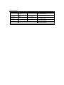
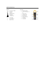
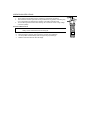
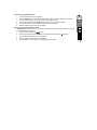
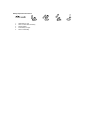
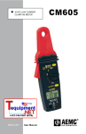
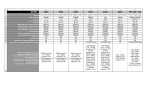
User's Manual
Digital AC Clamp Meter
Model 38390
WARRANTY
EXTECH INSTRUMENTS CORPORATION warrants this instrument to be free of defects in parts and workmanship for one year from date of
shipment (a six month limited warranty applies on sensors and cables). If it should become necessary to return the instrument for service during or
beyond the warranty period, contact the Customer Service Department at (781) 890-7440 ext. 210 for authorization. A Return Authorization (RA)
number must be issued before any product is returned to Extech. The sender is responsible for shipping charges, freight, insurance and proper
packaging to prevent damage in transit. This warranty does not apply to defects resulting from action of the user such as misuse, improper wiring,
operation outside of specification, improper maintenance or repair, or unauthorized modification. Extech specifically disclaims any implied warranties
or merchantability or fitness for a specific purpose and will not be liable for any direct, indirect, incidental or consequential damages. Extech's total
liability is limited to repair or replacement of the product. The warranty set forth above is inclusive and no other warranty, whether written or oral, is
expressed or implied.
REPAIR AND CALIBRATION SERVICES
Extech offers complete repair and calibration services for all of the products we
sell. For periodic calibration, NIST certification or repair of any Extech product, call
Tech Support
customer service for details on services available. Extech recommends that calibration
Hotlines
be performed on an annual basis to ensure calibration integrity.
781-890-7440 ext. 200
Copyright © 1999 Extech Instruments Corporation. All rights reserved
[email protected]
including the right of reproduction in whole or in part in any form.
www.extech.com
38390 V1.1 4/02
INTRODUCTION
Congratulations on your purchase of Extech’s 38390 AC Clamp Meter. This autoranging clamp meter measures AC
Current to 400A, DC/AC Voltage, Resistance, and Continuity. Proper use and care of this meter will yield years of reliable
service.
SAFETY
Safety Symbols
This symbol, adjacent to another symbol or
terminal, indicates the user must refer to the
manual for further information.
This symbol, adjacent to a terminal, indicates
that, under normal use, hazardous voltages
may be present
Double insulation
WARNING: This indicates that a potentially hazardous
condition which, if not avoided, could
result in death or serious injury.
CAUTION: This indicates that a potentially hazardous
condition which, if not avoided, could
result in injury or damage to the meter.
Safety Precautions
WARNING: Improper use of this meter can cause damage, shock, injury or death. Read and understand this users
manual before operating the meter.
1.
2.
3.
4.
5.
6.
7.
Always remove the test leads before making current measurements.
Always remove the test leads before replacing the batteries.
Inspect the condition of the jaws, test leads and the meter for any damage before operating the meter.
Repair or replace any damage before use.
Do not exceed the maximum rated input limits.
Use great care when making measurements especially when the voltages are greater than 25VAC rms
or 35VDC. These voltages are considered a shock hazard.
Always discharge capacitors and remove power from the device under test before performing Resistance
or Continuity tests.
Remove the batteries from the meter if the meter is to be stored for long periods.
SPECIFICATIONS
Function
AC Current
Range
40.00A
400.0A
400.0V
600V
400.0V
600V
0.3 to 400 Ω
Accuracy
± (2% + 15 digits)
Remarks
Frequency: 50/60Hz;
660A overload protection
AC Voltage
± (1.5% + 10 digits)
Frequency: 40Hz to 450Hz;
Input Z: 1MΩ; 660Vrms OL protect
DC Voltage
± (1% + 5 digits)
Input Z: 1MΩ;
660V overload protect
Resistance
± (1% + 5 digits)
-1.1 to -1.3V open circuit;
600Vrms overload protect
Continuity
-1.1 to -1.3V open circuit;
Audible tone <40Ω approximately
600Vrms overload protect
o
o
o
o
Note: Accuracy specified as ± (% of reading + number of digits) at 64 F to 82 F (18 C to 28 C) and RH<80%
Conductor Size
Operating principle
Battery type
Battery Life
Auto Power off
Range Selection
Display
Overload Indication
Low Battery Indication
Environmental conditions
Operating Temperature/Humidity
Storage Temperature/Humidity
Dimensions
Weight
0.9" (23mm ) maximum
Dual slope integration
2 x 1.55V button (ICE LR-44, NEDA 116A or A76)
200 hours
After 30 minutes
Automatic ranging
3-3/4 digit (3999 Count) LCD
"OL"
Battery icon
Installation Category II,Pollution degree 2,Altitude up to 2000 meters, Indoor
use only
o
o
32 to 104F (0 C to 40 C) / <80% RH
o
o
14 to 140F (-10 C to 60 C) / <70% RH
7.4 x 2.5 x 1.2” (188 x 62.5 x 30.5mm)
6.5 oz. (185g)
METER DESCRIPTION
Front panel
Symbols
AC Current or Voltage
1.
Jaw opening trigger
DC Voltage
2.
Function switch (OFF, A, V,
Ω)
Continuity
H
Display Data Hold
3.
COM input jack
A
Auto Range
4.
Transformer Jaws
Low Battery icon
5.
DATA HOLD key
6.
AC/DC Selector key
Units
V
Ω
A
Volt (voltage)
Ohm (resistance)
Amps (current)
7.
LCD Display
8.
VΩ input jack
OPERATING INSTRUCTIONS
Precautions
1.
2.
3.
Ensure that the selected meter function matches the measurement to be taken.
If the measured current is higher than the range selected for long periods, overheating may
occur compromising the safety and the operation of the meter’s internal circuits.
To avoid discharge risks and erroneous readings, do not measure current on high voltage
conductors (>600V).
AC Current Measurements
WARNING: Make sure that the test leads are disconnected from the meter’s terminals before
making current measurements with the clamp jaw.
1.
2.
3.
4.
Set the Function switch to the A range..
Press the trigger to open jaw. Fully enclose one conductor to be measured.
The clamp meter will automatically select the proper range (Auto Range).
Read the measured value from the LCD display.
DC and AC Voltage Measurements
1. Set the Function Switch to the V position.
2. Press the AC/DC key (directly below the HOLD key) to select AC or DC Voltage. The meter will
show the selection with an AC or DC symbol (upper left side of LCD).
3. Insert the black test lead to the COM input jack and the red test lead to the V jack.
4. Connect the test leads in PARALLEL with the circuit to be measured.
5. Read the measured value from the LCD display.
Resistance and Continuity Measurements
CAUTION: Before taking any in-circuit resistance measurements, remove power from the circuit under
test and discharge all capacitors.
1. Set the Function switch to the
Ω position.
2. Insert the black test lead to the COM input jack and the red test lead to the Ω input jack.
3. Connect test leads to the device to be measured.
4. Read the measured value from the LCD display.
5. If the resistance is < 40Ω (approx.) an audible signal will be heard.
Data Hold
Press the HOLD key momentarily to freeze the present reading on the LCD. "H" will appear in the display. Press the
HOLD key again to return to normal operation.
MAINTENANCE
WARNING: To avoid electrical shock or damage to the meter, keep moisture from entering the meter housing. Also,
remove the test leads before opening the meter housing.
Cleaning
Periodically wipe the case with a damp cloth and mild detergent. Do not use abrasives or solvents.
Battery Replacement
When the low battery symbol appears on the LCD, replace the meter’s two button-batteries.
1. Remove power and remove test leads from meter
2. Remove the two rear Phillips screws and open the meter housing.
3. Remove and replace the two 1.55V button batteries per the following illustrations.
4. ICE replacement number: LR-44; NEDA replacement numbers: 116A or A76.
5. Replace the rear screws.
Battery Replacement Illustrations
1.
2.
3.
4.
5.
Slide battery to right
Press on other side to lift battery
Remove battery
Insert battery on angle
Press to seat battery