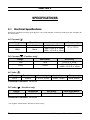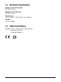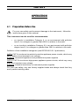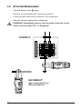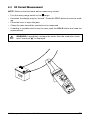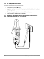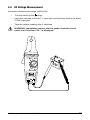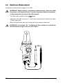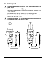
1
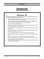
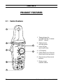
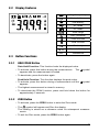
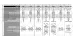
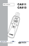
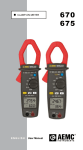
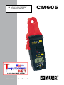
AC/DC LOW CURRENT CLAMP-ON METER ENGLISH User Manual CM605 Statement of Compliance Chauvin Arnoux®, Inc. d.b.a. AEMC® Instruments certifies that this instrument has been calibrated using standards and instruments traceable to international standards. We guarantee that at the time of shipping your instrument has met its published specifications. An NIST traceable certificate may be requested at the time of purchase, or obtained by returning the instrument to our repair and calibration facility, for a nominal charge. The recommended calibration interval for this instrument is 12 months and begins on the date of receipt by the customer. For recalibration, please use our calibration services. Refer to our repair and calibration section at www.aemc.com. Serial #: _ ________________________________ Catalog #: 7000.02 Model #: CM605 Please fill in the appropriate date as indicated: Date Received: __________________________________ Date Calibration Due: ________________________ Chauvin Arnoux®, Inc. d.b.a AEMC® Instruments www.aemc.com Table of Contents 1. INTRODUCTION................................................................................ 2 1.1 International Electrical Symbols............................................................3 1.2 Receiving Your Shipment......................................................................3 1.3 Ordering Information.............................................................................3 2. PRODUCT FEATURES....................................................................... 4 2.1 Control Features...................................................................................4 2.2 Display Features...................................................................................5 2.3 Button Functions...................................................................................5 2.3.1 HOLD/PEAK Button................................................................5 2.3.2 ZERO Button............................................................................5 3. SPECIFICATIONS............................................................................. 6 3.1 Electrical Specifications........................................................................6 3.2 Environmental Specifications................................................................7 3.3 Mechanical Specifications.....................................................................8 3.4 Safety Specifications.............................................................................8 4. OPERATION..................................................................................... 9 4.1 Preparation Before Use........................................................................9 4.2 AC Current Measurement...................................................................10 4.3 DC Current Measurement...................................................................11 4.4 AC Voltage Measurement...................................................................12 4.5 DC Voltage Measurement...................................................................13 4.6 Resistance Measurement...................................................................14 4.7 Continuity Test.....................................................................................15 4.8 Analog Output.....................................................................................16 5. MAINTENANCE.............................................................................. 17 5.1 Warning . ............................................................................................17 5.2 Battery Replacement..........................................................................17 5.3 Cleaning..............................................................................................17 Repair and Calibration.........................................................................................18 Technical and Sales Assistance..........................................................................18 Limited Warranty.................................................................................................19 Warranty Repairs.................................................................................................19 CHAPTER 1 INTRODUCTION Warning These safety warnings are provided to ensure the safety of personnel and proper operation of the instrument. 2 • Read the instruction manual completely and follow all safety information before operating this instrument. • Only use leads that comply with the IEC/EN 61010. Before using them, make sure that they are in safe working order. • Only use factory supplied leads. • Never exceed the protection limit values indicated in the specifications for each type of measurement. • Never measure current while the test leads are connected to the input jacks. • Use extreme caution when measuring live systems with voltages greater than 50VDC or 30VAC. • Do not perform resistance or continuity tests on a live circuit. • Use extreme care when working around bus bars and bare conductors. • Do not use the meter in overrange/overload conditions (OL). • When the multimeter clamp is linked to the measurement circuits, do not touch any unused terminals. • Before changing the function, disconnect the measurement leads from the circuit measured. AC Clamp-on Meter Model CM605 1.1 International Electrical Symbols This symbol signifies that the instrument is protected by double or reinforced insulation. Use only specified replacement parts when servicing the instrument. This symbol on the instrument indicates a WARNING and that the operator must refer to the user manual for instructions before operating the instrument. In this manual, the symbol preceding instructions indicates that if the instructions are not followed, bodily injury, installation/sample and product damage may result. Risk of electric shock. The voltage at the parts marked with this symbol may be dangerous. 1.2 Receiving Your Shipment Upon receiving your shipment, make sure that the contents are consistent with the packing list. Notify your distributor of any missing items. If the equipment appears to be damaged, file a claim immediately with the carrier and notify your distributor at once, giving a detailed description of any damage. Save the damaged packing container to substantiate your claim. Do not use an instrument that appears to be damaged. 1.3 Ordering Information Model CM605...................................................................................Cat. #7000.02 Includes clamp-on meter, lead set (red & black lead) with needle point test probes, carrying case, 2x1.5V AAA batteries and a user manual. AC Clamp-on Meter Model CM605 3 CHAPTER 2 PRODUCT FEATURES 2.1 Control Features 1 1. Tapered jaws for crowded wiring or areas (Ø.45"- 12mm) 2 Press 2 Sec HOLD PEAK OFF 3 6 7 2. Safety barrier anti-slip guard 3. Lever for jaw opening/closing 4. LCD display 5. COM (Black) and Positive (Red) input terminal jacks ZERO 6. Data hold and Peak hold buttons 7. Rotary range selector switch 4 COM 600V CAT II 5 4 AC Clamp-on Meter Model CM605 2.2 Display Features Negative polarity Auto shutdown Low battery AC mode DC mode Auto range Zero (Relative) Peak function Hold function Continuity A V Ω Current / Voltage Resistance 2.3 Button Functions 2.3.1 HOLD/PEAK Button Data Hold Function: This function locks the displayed value. • To activate, press this button during the measurement. The appears and the measurement is locked. symbol • To deactivate, press the button again. Peak Hold Function: This function displays the peak value. • To activate, press this button during a measurement until the appears. symbol • The highest measurement is stored in memory. • To deactivate the PEAK function, press and hold down the button for approximately 2 seconds. 2.3.2 ZERO Button • To activate, press the ZERO button to enter the Zero mode. • The symbol will appear and Zero the display. The reading is stored as a reference value for subsequent measurements. • To exit the Zero mode, press the ZERO button again. AC Clamp-on Meter Model CM605 5 CHAPTER 3 SPECIFICATIONS 3.1 Electrical Specifications Reference Conditions: Accuracy given @ 23°C ± 5°C, 80% RH Max, Conductor centered in jaws, 45-65Hz, No DC Component. AC Current ( ) Range Resolution Accuracy Frequency 10A 1mA 100A 10mA 2.0% R ± 10cts 80A: 2.0% R ± 10cts >80A: 3.5% R ± 10cts 50 to 500Hz DC Current ( ) - Positive only* Range Resolution Accuracy 10A 1mA 100A 10mA 2.5% R ± 10cts 80A: 2.5% R ± 10cts >80A: 4.5% R ± 10cts AC Volts ( ) Range 600V Resolution 100mV Accuracy 1.5% R ± 5cts Impedance 10MΩ, <50pF Frequency 40 to 500Hz Overload Protection: 660Vrms DC Volts ( ) - Positive only* Range 600V Resolution 100mV Accuracy 1.0% R ± 2cts Input Impedance 10MΩ Overload Protection: 660Vrms * For negative measurement, add 2cts to the accuracy 6 AC Clamp-on Meter Model CM605 Resistance (Ω) Range 10kΩ (9999Ω) Continuity ( Resolution 1Ω Accuracy 1.0% R ± 3cts Test Voltage <3.0VDC Protection 600Vrms ) Buzzer <100Ω ± 25Ω Resolution 1Ω Test Voltage <3.0VDC Protection 600Vrms Analog Output Range AAC & ADC Output 10mV/A through front banana jacks Frequency Output Impedance 0 to 20kHz @ ± 3db 3kΩ, <50pF Digital display: 10,000-count 4 digit LCD display (9999 max) Polarity: When a negative signal is applied, the Overload: If the range is exceeded, the symbol appears. symbol is displayed. Low Battery Indicator: is displayed when the voltage supplied by the batteries is lower than the operating voltage. Power Supply: 2 batteries - 1.5V type AAA (LR03) Auto-off: Automatic shut down after approx 10 minute with over-ride Sampling: Approx 2 measurements/second 3.2 Environmental Specifications Operating Temperature: 32° to 104°F (0° to 40°C), < 80% RH max non-condensing Storage Temperature: 14° to 140°F (-10° to 60°C), < 70% RH max non-condensing Altitude: 6000 ft (2000m) AC Clamp-on Meter Model CM605 7 3.3 Mechanical Specifications Maximum Cable Diameter: Ø 0.45" (12mm) Maximum Jaw Opening: Ø 0.60" (15mm) Dimensions: 7.44 x 2.80 x 1.46" (189 x 71 x 37mm) Weight: 6.5 oz (180g) 3.4 Safety Specifications IEC/EN 61010-1, 600V CAT II, 300V CAT III - Insulation: Class II - Pollution Degree: 2 8 AC Clamp-on Meter Model CM605 CHAPTER 4 OPERATION 4.1 Preparation Before Use For your own safety and to prevent damage to the instrument, follow the instructions given in this manual. This instrument can be used for measurements: • on circuits in installation Category II, in an environment with pollution level 2, for voltages no greater than 600V in relation to the earth. • or on circuits in installation Category III, in an environment with pollution degree level 2, for voltages no greater than 300V in relation to the earth. Definition of the installation categories (see IEC/EN 61010-1 publication): CAT II: CAT II circuits are household or similar appliance power circuits, which may carry medium-level transient over-voltage. Example: household appliance and portable tool power supplies CAT III: CAT III circuits are high-power appliance power circuits, which may carry high-level transient over-voltage. Example: industrial machinery or instrument power supplies For your own safety, only use factory supplied leads and always check that they are in perfect working order. AC Clamp-on Meter Model CM605 9 4.2 AC Current Measurement • Turn the switch to the range. • Remove the test leads before measuring current . • Clamp the jaws around the conductor to be measured. • Take the current reading after it stabilizes. WARNING: Immediately remove the test probes from the circuit under test if overload “OL” is displayed. Press 2 Sec HOLD PEAK OFF ZERO COM 10 ZERO 600V CAT II COM Press 2 Sec HOLD PEAK OFF CORRECT INCORRECT (two conductors from different phases) 600V CAT II AC Clamp-on Meter Model CM605 4.3 DC Current Measurement NOTE: Remove the test leads before measuring current • Turn the rotary range switch to the range. • If needed, the display may be “zeroed”. Press the ZERO button to zero the reading. • Press the lever to open the jaws. • Clamp the jaws around the conductor to be measured. • If reading is unstable and is hard to read, push the HOLD button and read the measurement. WARNING: Immediately unclamp the meter from the conductor under test if overload " " is displayed. s es Pr Sec 2 LD HOEAK FF O P RO ZE M CO AC Clamp-on Meter Model CM605 0V 60 T II CA 11 4.4 AC Voltage Measurement Automatic measurement range: 600VAC/DC • Turn the switch to the range. • Insert the red lead to the red “+” input jack and the black lead to the black "COM" input jack. • Bring the test probe tips into contact with the test points. • Take the voltage reading after it stabilizes. WARNING: Immediately remove the test probes from the circuit under test if overload “OL” is displayed. Press 2 Sec HOLD PEAK OFF ZERO COM 600V CAT II 12 AC Clamp-on Meter Model CM605 4.5 DC Voltage Measurement Automatic measurement range: 600VAC/DC • Turn the switch to the range. • Insert the red lead to the red “+” input jack and the black lead to the black "COM" input jack. • Take the voltage reading after it stabilizes. WARNING: Immediately remove the test probes from the circuit under test if overload “OL” is displayed. Press 2 Sec HOLD PEAK OFF ZERO COM 600V CAT II AC Clamp-on Meter Model CM605 13 4.6 Resistance Measurement Automatic measurement ranges: 0 to 10kΩ WARNING: When making a resistance measurement, make sure that the power is off (dead circuit). It is also important that all capacitors in the measured circuit be fully discharged. • Turn the rotary switch to the range. • Insert the red lead to the red “+” input jack and the black lead to the black "COM" input jack. • Bring the test probe tips into contact with the sample under test. WARNING: If overload “OL” is displayed, the resistance exceeds the measurement range or the circuit is open. Press 2 Sec HOLD PEAK OFF ZERO COM 600V CAT II 14 AC Clamp-on Meter Model CM605 4.7 Continuity Test WARNING: When testing continuity, make sure that the power is off (dead circuit). • Turn the rotary switch to the range.. • Insert the red lead to the red “+” input jack and the black lead to the black "COM" input jack. • Bring the test probe tips into contact with the sample under test. • The buzzer sounds when the circuit to be checked is DC or has a resistance of less than 100Ω ± 25Ω. WARNING: If overload "OL" is displayed, the continuity exceeds the measurement range or the circuit is open. Press 2 Sec HOLD PEAK OFF Press 2 Sec HOLD PEAK OFF ZERO ZERO COM COM 600V CAT II AC Clamp-on Meter Model CM605 600V CAT II 15 4.8 Analog Output • Turn the rotary switch to the or range. • Insert the red lead to the red “+” input jack and the black lead to the black "COM" input jack. • Connect the ends of both cables to an oscilloscope or another multimeter. • Clamp the jaws around the conductor to be measured. • Read the analog signal on the oscilloscope or multimeter. - If the signal measured is continuous, the output signal will be DC. - If the signal measured is alternating, the output signal will be AC. Press 2 Sec HOLD PEAK OFF ZERO COM 600V CAT II 16 AC Clamp-on Meter Model CM605 CHAPTER 5 MAINTENANCE 5.1 Warning • Remove the test leads from any input before opening the case. Do not operate the instrument without a battery case cover. • To avoid electrical shock, do not attempt to perform any servicing unless you are qualified to do so. • If the meter is not going to be used for a long period of time, take out the batteries. Do not store the meter in high temperatures or high humidity. • To avoid electrical shock and/or damage to the instrument, do not get water or other foreign agents into the probe. 5.2 Battery Replacement • The batteries will need to be replaced when the display. symbol appears on the • The meter must be in the OFF position and disconnected from any circuit or input. • Remove the battery cover screws with a screwdriver. • Replace the old batteries with two new 1.5V AAA (LR03) batteries. • Replace the battery compartment cover and tighten the screws. 5.3 Cleaning • To clean the instrument, wipe the case with a damp cloth and mild detergent. Do not use abrasives or solvents. • Do not get water inside the case. This may lead to electrical shock or damage to the instrument. AC Clamp-on Meter Model CM605 17 Repair and Calibration To ensure that your instrument meets factory specifications, we recommend that it be scheduled back to our factory Service Center at one-year intervals for recalibration, or as required by other standards or internal procedures. For instrument repair and calibration: You must contact our Service Center for a Customer Service Authorization Number (CSA#). This will ensure that when your instrument arrives, it will be tracked and processed promptly. Please write the CSA# on the outside of the shipping container. If the instrument is returned for calibration, we need to know if you want a standard calibration, or a calibration traceable to N.I.S.T. (Includes calibration certificate plus recorded calibration data). Ship To: AEMC® Instruments 15 Faraday Drive Dover, NH 03820 USA Tel: (800) 945-2362 (Ext. 360) (603) 749-6434 (Ext. 360) Fax:(603) 742-2346 or (603) 749-6309 [email protected] (Or contact your authorized distributor) Costs for repair, standard calibration, and calibration traceable to N.I.S.T. are available. NOTE: You must obtain a CSA# before returning any instrument. Technical and Sales Assistance If you are experiencing any technical problems, or require any assistance with the proper operation or application of your instrument, please call, mail, fax or e-mail our technical support team: AEMC® Instruments 200 Foxborough Boulevard Foxborough, MA 02035 USA Phone:(800) 343-1391 (508) 698-2115 Fax: (508) 698-2118 [email protected] www.aemc.com NOTE: Do not ship Instruments to our Foxborough, MA address. 18 AC Clamp-on Meter Model CM605 Limited Warranty The Model CM 605 is warranted to the owner for a period of one year from the date of original purchase against defects in manufacture. This limited warranty is given by AEMC®, not by the distributor from whom it was purchased. This warranty is void if the unit has been tampered with, abused or if the defect is related to service not performed by AEMC®. For full and detailed warranty coverage, go to www.aemc.com. The warranty information is located in our customer service section. What AEMC® will do: If a malfunction occurs within the one-year period, you may return the instrument to us for repair, provided you submit a proof of purchase. AEMC® will, at its option, repair or replace the faulty material. Warranty Repairs What you must do to return an Instrument for Warranty Repair: First, request a Customer Service Authorization Number (CSA#) by phone or by fax from our Service Department (see address below), then return the instrument along with the signed CSA Form. Please write the CSA# on the outside of the shipping container. Return the instrument, postage or shipment pre-paid to: AEMC® Instruments Service Department 15 Faraday Drive • Dover, NH 03820 USA Tel: (800) 945-2362 (Ext. 360) (603) 749-6434 (Ext. 360) Fax: (603) 742-2346 or (603) 749-6309 Caution: To protect yourself against in-transit loss, we recommend you insure your returned material. NOTE: You must obtain a CSA# before returning any instrument. AC Clamp-on Meter Model CM605 19 Notes: 20 AC Clamp-on Meter Model CM605 11/09 99-MAN 100346 v1 Chauvin Arnoux®, Inc. d.b.a. AEMC® Instruments 15 Faraday Drive • Dover, NH 03820 USA • Phone: (603) 749-6434 • Fax: (603) 742-2346 www.aemc.com