1
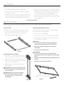
INSTRUCTION BOOK FOR
Multi-Mask Imager
Important Safety
When using your video equipment, basic safety precautions should always be followed, including the following:
1. Read and understand all instructions before using.
2. Position the cord so that it will not be tripped over, pulled,
or contact hot surfaces.
3. If an extension cord is necessary, a cord with a current rating
at least equal to that of the appliance should be used. Cords
rated for less amperage than the appliance may overheat.
4. To reduce the risk of electric shock, do not disassemble this
appliance. Contact an authorized service dealer when repair
work is required. Incorrect reassembly can cause electric
shock when the appliance is used subsequently.
5. The use of an accessory attachment not recommended
by the manufacturer may cause a risk of fire, electric shock,
or injury to persons.
Save These Instructions
Mounting The Frame
Professional mounting techniques should be adhered to. Da-Lite Screen Company cannot be liable for substandard
or faulty installations.
Frame Assembly
Unpacking and Unrolling the Screen
Assembly of the screen should be in a clean environment.
The viewing side of the screen surface is rolled to the inside.
The screen surface is rolled lengthwise.
1. Connect the four frame pieces by matching the colored
tapes on the ends of the frame pieces. See Figure 1.
2. Secure with the supplied 5/16" setscrews.
1. Remove screen from packaging.
2. On a clean floor, unroll the screen surface viewing side up.
3. Allow the paper to unroll between backside of the screen
surface and floor. See Figure 3.
CAUTION:
• Be careful not to touch or scratch the viewing side
of the surface with fingernails and any sharp tools.
• Do not use any tools to fasten the screen surface
to the frame.
• Do not fold or crease the screen.
Figure 1
ATTENTION:
• Prenez soin de ne pas toucher ou rayer la face de
projection de l'écran avec les ongles ou tout autre objet
pointu.
Positioning the Frame on the Wall
1. Without the screen fabric attached, position the
frame on the wall at the location you desired.
• N'utilisez aucun outil pour attacher la surface de l'écran
au cadre.
2. Make sure the unit is level and plumb. (You may
need to use shims between the brackets and the
wall to achieve vertical plumb.)
• Ne pliez pas ou ne froissez pas l'écran
3. Mark the position of the bracket holes on the
wall. See Figure 2.
CAUTION: If the screen is not mounted so that
it is level and plumb, horizontal masking may
jam on retraction.
ATTENTION: Si l'écran n'est pas installé de
sorte qu'il soit droit et plat, le masquage
horizontal risque de se coincer lors de
l'enroulement.
Figure 2
2
Figure 3
Mounting The Frame
Electrical Wiring
Attaching the Screen Surface to Frame
Electrical wiring is required for each mask roller motor. The
vertical masking systems have one motor at the frame top.
Horizontal masking systems have one motor at the frame top
and one at the bottom.
1. Place the frame over the screen surface.
2. While lifting the frame with one hand, snap the screen surface
onto the frame. Gently allow the screen to stretch onto snaps.
See Figure 4. Attach the snaps on the top corners and top
horizontal first, lift the frame to a vertical position to finish
attaching the rest of the snaps.
A motor requires standard 120V/220V input. All connections are
made to the electrical box on the audience left side of the unit.
Horizontal
Mask
Connection
Vertical Mask
Connection
Figure 4
Horizontal
Mask
Connection
Tensioning the Bottom Masking Panel
1. Carefully remove all tape strips securing surfaces around
rollers. Slats should move freely. See Figure 5.
2. Locate the spring tension cables on either side of the unit.
Figure 6
3. Connect the eye snap to the eyelet on the bottom masking
panel bar. See Figure 5. You will need to pull the cable slightly.
4. Repeat for the other side.
Surface
Slat
Tape Strip
Spring Tension Cable
Eye
Snap
Eyelet
Slat
Figure 5
3
Multi-Mask Imager Installation
Installing the High Voltage Switch Control (Standard)
Three standard 3-position wall switches are supplied. The high-voltage control is connected to the electrical source.
It alternates directions of mask motion by means of a hot lead, using the 3-position switches.
120V Wiring Diagram
Red
Rocker
Switch
Up
Up Black
Common
White
Down Red
To Motor
White
Black
Black With
Yellow
Off
Down
AC Common
Operating Switch,
Switch Box, And
Plate Furnished
With Screen
(SPDT With
Center Off)
In Multiple Control
Installations This Switch
Is Replaced By The Low
Voltage Control,
Operated From Push
Button Stations.
AC Hot
120V. 60-HZ 2.5 Max. Amp
Side View
Of Switch
And Box
This Switch Cannot Be Used With LVC.
NOTE: A single switch cannot be used to operate more than
one screen. Contact the factory for further information.
220 / 240V
Wiring Diagram
Blue (Common)
Black (Down)
Brown (Up)
To Motor
Up
Brown/Yellow
Off
Down
Rocker
Switch
Rear View Of DPDT,
With Center Off
Operating Switch,
Switch Box, And
Plate Furnished
With Screen.
Brown AC Hot
Blue AC Common
220/240V. AC 50HZ
2 Amp. Max
Blue Jumper Wire
NOTE: A single switch cannot be used to operate more than
one screen. Contact the factory for further information.
4
Junction
Box
In Multiple Control
Installations This Switch Is
Replaced By The Low
Voltage Control, Operated
From Push Button Stations.
NOTE:
Must Be Wired To Conform To
Local Wiring Code. This Switch
Cannot Be Used With L.V.C.
Hanging The Screen On The Wall
1. Attach the wall brackets to the wall using appropriate
fasteners at previously marked locations.
2. Attach the Side Covers to the frame by sliding the Bolts on
the Side Cover tube into the openings on the top and bottom
brackets. See Figure 7.
Opening
Side
Side
Cover
Figure 7
Operating The Mask
Adjusting The Mask Extension
When you lower or retract a mask, it will stop at its present limit.
If an obstacle (such as a person or furniture) gets in the path of a
mask as it is lowered, you should use the switch control to stop
the mask's motion; it will not automatically stop if it hits an
obstacle.
CAUTION: Improper adjustment of the limit switches
can cause irreparable damage to a mask itself, resulting
in voiding the factory warranty.
ATTENTION: Un réglage inapproprié des interrupteurs de
fin de course peut endommager de manière irréversible le
masque et entraîner l'annulation de la garantie.
NOTE: The horizontal masking panels move more slowly than
the vertical masking panels. The slower motion allows you to
adjust the image area with greater precision.
When a mask is not in use, you should store it in the fully
retracted position.
CAUTION: Do not operate the motor when any of the
following occurs:
• The unit emits any smoke, heat, abnormal noise
or unusual odor.
The extension and retraction limit switches have been preset
at the factory. In general, we advise you to avoid readjusting
these switches.
In some cases, to enable proper alignment of the displayed
image on the screen, you may need to adjust the extension
of a mask. If adjustment to the extension is necessary, carefully
follow these instructions.
• If any of these situations occur, call a qualified
service person.
WARNING! A mask is fully retracted when the batten
is flush with the bottom of the case. Do not attempt
adjustments with a retraction (UP) limit switch that will
further retract a mask. Incorrect adjustment of that
switch will cause severe mask damage. Please consult the
factory if you have any questions.
• The unit is damaged in some way, such as damage from a
water leak.
ATTENTION: Ne mettez pas le moteur en marche lorsque :
• L'unité émet de la fumée, un bruit anormal, de la chaleur
ou une odeur inhabituelle.
• L'unité est endommagée d'une quelconque façon (ex.
dommage dû à une fuite d'eau).
• Si l'une de ces situations se produisait, appelez un
technicien qualifié.
AVERTISSEMENT! Un masque est complètement rétracté
lorsque la latte est alignée avec le bas du caisson.
N'essayez pas d'effectuer des réglages avec un
interrupteur de fin de course d'enroulement (VERS LE
HAUT) qui causera une rétraction additionnelle d'un
masque. Un réglage incorrect de cet interrupteur peut
endommager sérieusement le masque. Veuillez contacter
l'usine si vous avez des questions.
5
Adjusting The Mask Extension (Continued)
Modifying the Extension of the Mask
1. You can increase the extension of a mask up to 3" past the
factory preset stop, or you can decrease the extension by
approximately 4-6" from the factory preset stop. Do not
attempt to modify a mask extension beyond these
recommended amounts.
1
2. The limit switches are accessed through openings located on
the left side of the frame as shown in Figure 8.
4
2
3
Horizontal Mask
Vertical Mask
3. Horizontal mask units have limit switches at the top and
bottom of the screens, a set for each roller tube.
Screen
WARNING! The up limit switch(es) retract the batten
further into the unit. Adjusting it is not advised. Refer to 1,
3 or 5 as appropriated in Figure 8.
AVERTISSEMENT! Le(s) interrupteur(s) de fin de course
supérieur(s) rétracte(nt) la latte à l'intérieur de l'unité. Le
réglage n'est pas recommandé. Référez-vous au points 1,
3 ou 5 tel qu'indiqué dans la figure 8.
To Increase a Mask's Fully Extended (Mask Down)
Stop Position:
5
Figure 8
1. Lower the mask to its current stop position.
2. Locate the down limit switch(es) located on the left side of
the frame. Refer to 2, 4 or 6 as appropriate in Figure 8. Use an
Allen wrench to turn the switch in a counterclockwise
direction. If the power is on, the mask will drop incrementally
as the switch is turned. NOTE: One complete turn of the
switch will make approximately a 1/2" change in the mask's
stop position.
To Decrease the Screen Extension:
1. Lower the mask until it is extended about halfway down.
2. Locate the down limit switch(es) located on the left side of
the frame. Refer to 2, 4 or 6 as appropriate in Figure 8. Use
an Allen wrench to turn the switch in a clockwise direction.
NOTE: One complete turn of the switch will make
approximately a 1/2" change in the mask's stop position.
Horizontal Mask
6
Screen Care And Cleaning
With reasonable care, you expect many years of trouble-free use
of your Da-Lite projection screen.
We encourage you to keep your screen clean. Avoid getting any
foreign material on the screen. It may not be possible to remove
scratches, paint, ink, etc.
General Maintenance
The screen surface on your Multi-Mask Imager is delicate.
Special attention to these instructions should be followed
when cleaning.
3. Activate the mask in the down direction until it reaches
the newly reduced stop position. Repeat this procedure
until the desired stop position is reached.
• A draftsman-style brush may be used to lightly whisk away
any loose dirt or dust particles. (This type of brush is usually
available at office supply stores.)
Once you have made the adjustment, whenever you lower
the mask, it will automatically stop at the new position.
• For tougher spots, use a mild solution detergent, water and a
soft cloth. Rub lightly. Blot with a damp sponge to absorb
excess water.
Do not use any other cleaning materials on the screen.
Replacement Parts and Service
No user-serviceable parts are contained within the unit.
Contact your dealer or the factory if you require part
replacement or service.
6
Troubleshooting
Refer to the following guidelines if you encounter a difficulty in the operation of your Da-Lite Multi-Mask Imager screen.
Problems related to electrical or motor function may require a qualified service person or electrician.
Should you have a problem that is not addressed here, call Da-Lite customer service.
Symptom
Cause
Solution
No 120V/220V power available.
Check to see if the circuit breaker has switched off.
Reset if needed.
Outboard switching problem.
Check outboard switching apparatus. Check voltage
availability. Contact and Electrician..
Mask won't operate.
Have an electrician or qualified service person check
the connection as follows:
Mask won't roll up or down
(even though power is
available).
Bad connection at switch.
• If you have a high voltage control switch,
check switch line connections.
• If you have a low voltage control unit,
check switch line connections.
Mask roller chatters when
power is activated.
Can be caused by voltage drop, bad connections
or a defective switch.
Have an electrician or qualified service person
check all hook-ups including all outboard wiring.
Unit hums in up mode (Mask
has already retracted).
The mask batten is retracting too far into the case.
Failure to correct can damage motor. Do not use
the unit until this problem is resolved.
Have a qualified service person adjust the UP limit switch.
Turn the adjusting screw clockwise.
Mask drops when up direction
is activated (grinding noise
occurs).
Drop in voltage.
Mask motor requires full voltage. Have an electrician or
qualified service person check the available voltage.
Mask continues past bottom
stop position.
White limit switch is out of adjustment.
Re-adjust the Down limit switch. See pp. 6-7 of this manual.
Batten retracts too far into
frame.
Yellow limit switch out of adjustment. Failure to
correct can damage motor. Do not use the unit
until this problem is resolved.
Have a qualified service person adjust the
UP limit switch. See pp. 6-7 of this manual.
Dirt, fingerprints, marks, etc. on
screen surface.
Improper handling of screen.
Brush off or use a mild detergent solution
with clean rag or cotton swab.
Indentations appear on screen
surface.
Debris or particles adhering to screen
due to static cling.
Check back of screen: gently brush debris away by hand.
Horizontal mask jams upon
retraction.
The unit was not level and plumb when mounted.
Remount the unit making sure that it is level and plumb.
7
LIMITED ONE YEAR WARRANTY ON DA-LITE PRESENTATION PRODUCTS
Milestone AV Technologies LLC warrants certain Da-Lite branded products to the original purchaser only, to be free from defects in
materials and workmanship for a period of one (1) year from the date of purchase by the original purchaser; provided they are properly
operated according to Da-Lite's instructions and are not damaged due to improper handling or treatment after shipment from the
factory.
This warranty does not apply to equipment showing evidence of misuse, abuse or accidental damage, or which has been tampered
with or repaired by a person other than authorized Da‑Lite personnel.
Da-Lite’s sole obligation under this warranty shall be to repair or to replace (at Da-Lite’s option) the defective part of the merchandise.
Returns for service should be made to your Da-Lite dealer. If it is necessary for the dealer to return the screen or part to Da-Lite,
transportation expenses to and from Da-Lite are payable by the purchaser and Da-Lite is not responsible for damage in shipment.
To protect yourself against damage or loss in transit, insure the product and prepay all transportation expenses.
TO THE MAXIMUM EXTENT PERMITTED BY APPLICABLE LAW, THIS WARRANTY IS IN LIEU OF ALL OTHER WARRANTIES, EXPRESS
OR IMPLIED, INCLUDING WARRANTIES AS TO FITNESS FOR USE AND MERCHANTABILITY. Any implied warranties of fitness for use,
or merchantability, that may be mandated by statute or rule of law are limited to the one (1) year warranty period. This warranty gives
you specific legal rights, and you may also have other rights, which vary from state-to-state. TO THE MAXIMUM EXTENT PERMITTED
BY APPLICABLE LAW, NO LIABILITY IS ASSUMED FOR EXPENSES OR DAMAGES RESULTING FROM INTERRUPTION IN OPERATION
OF EQUIPMENT, OR FOR INCIDENTAL, DIRECT, OR CONSEQUENTIAL DAMAGES OF ANY NATURE.
In the event that there is a defect in materials or workmanship of a Da-Lite product, you may contact our Sales Partners at PO Box 137,
Warsaw, IN 46581-0137, (574) 267-8101, (800) 622-3737.
IMPORTANT: THIS WARRANTY SHALL NOT BE VALID AND DA-LITE BRANDED PRODUCTS SHALL NOT BE BOUND BY THIS
WARRANTY IF THE PRODUCT IS NOT OPERATED IN ACCORDANCE WITH THE DA-LITE WRITTEN INSTRUCTIONS.
Keep your sales receipt to prove the date of purchase and your original ownership.
A Milestone AV Technologies Brand
3100 North Detroit Street
Warsaw, Indiana 46582
P: 574.267.8101 or 800.622.3737
F: 574.267.7804 or 877.325.4832
E: [email protected]
www.da-lite.com
DL–0287 (Rev. 2) 10.14
© 2014 Milestone AV Technologies LLC. Printed in U.S.A.
94727