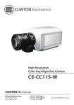
1
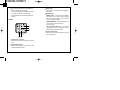
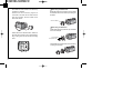
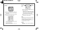
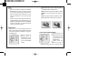
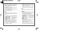
Digital Day & Night
COLOR CAMERA
USER MANUAL
CAUTION
RISK OF ELECTRIC SHOCK
DO NOT OPEN
CAUTION :
TO REDUCE THE RISK OF ELECTRIC SHOCK,
DO NOT REMOVE COVER(OR BACK),
NO USER SERVICEABLE PARTS INSIDE.
REFER WERVICING TO QUALIFIED
SERVICE PERSONNEL.
The lightning flash with an arrowhead symbol, within an
equilateral triangle is intended to alert the user to the
presence of uninsulated dangerous voltage within the
product's enclosure that may be of sufficient magnitude to
constitute a risk of electric shock to persons.
The exclamation point within an equilateral triangle is
intended to alert the user to the presence of important
operating and maintenance (servicing) instructions in the
literature accompanying the appliance.
INFORMATION - This equipment has been tested and found to comply
with limits for a Class A digital device, pursuant to part 15 of the FCC
Rules.
These limits are designed to provide reasonable protection against
harmful interference when the equipment is operated in a commercial
environment.
This equipment generates, uses, and can radiate radio frequency energy
and, if not installed and used in accordance with the instruction manual,
may cause harmful interference to radio communications. Operation of this
equipment in a residential area is likely to cause harmful interference in
which case the user will be required to correct the interference at his own
expense.
WARNING - Changes or modifications not expressly approved by the
manufacturer could void the user's authority to operate the equipment.
CAUTION : To prevent electric shock and risk of fire hazards : Do NOT
use power sources other than that specified.
Do NOT expose this appliance to rain or moisture.
This installation should be made by a qualified service person and
should conform to all local codes
Warning
The camera needs periodic inspection.
Contact an authorized technician for
Contents
1. Features
4
2. Components & Cable Connection
6
3. Names and functions of parts
7
inspection.
Stop using your camera when you find
a malfunction.
If you use your camera around smoke or
unusual heat for a long time, fire may be
caused.
Do not Install the camera on a surface
4. Installation & Dimension
10
5. Setup Menu Operation
16
6. Special Menu operation
27
7. Troubleshooting
36
8. Specifications
38
that can not support it.
Unless the surface is suitable, it could
cause falling or other hazards.
Do not hold plug with wet hands.
It could cause an electric shock.
Do not disassemble the camera.
It may result in fire, electric shock or other
hazards.
Do not use the camera close to a gas
or oil leak.
It may result in fire or other hazards.
2
3
1. Features
Horizontal Resolution 530 TVLines
Clear image quality has been achieved by
employing a SONY CCD with 410,000 (effective)
pixels, which provides a horizontal resolution of
530 TV lines.
DAY & NIGHT
This camera has a function that automatically
selects the mode that is appropriate for daytime or
night-time conditions The COLOR mode operates
in daytime conditions to provide optimum colors,
and BW mode operates in nighttime conditions to
enhance the definition of the image.
Electronic IRIS
The electronic IRIS function enables continuous
automatic control of the shutter between
1/60~1/120,000 seconds.
PRIVACY Function
The PRIVACY function conceals the areas you do
not wish to appear on the screen.
4
High Sensitivity
The built-in high sensitivity SONY COLOR CCD
enables a clear image even in 0.3Lux(0.1Lux
B/W) or as low as 0.002Lux with SENS-UP.
DNR (Digital Noise Reduction)
The amount of low illuminance noise has been
significantly reduced, and the signal-to-noise ratio
(S/N ratio) as well as horizontal resolution have
been improved, resulting in a clear and sharp
image display even in the dark.
Controlled by OSD Menu
The camera can be controlled by selecting text
displayed on the monitor screen.
Additional Functions
SENS-UP, MOTION DETECTION, MIRROR,
SHARPNESS and SYNC (INT/LL) functions are
also available.
5
2. Components
1) COLOR CAMERA
3. Names and Functions of Parts
DAY &
NIGHT,
DSS
00F
DCC-5CAMERA
R
N COLO
LUTIO
HIGH
RESO
T, DSS
NIGH
DAY &
00F
DCC-5CAMERA
LOR
N CO
LUTIO
HIGH
RESO
2) AUTO IRIS LENS
CONNECTION PLUG
1) Front
3) C-MOUNT ADAPTOR
Lens protection cap
Please cover the lens when not using it.
CS-Mount lens adaptor
Please attach the CS-Mount lens here.
Back Focus clamp screw
Please loosen the clamp screw with a
screwdriver before adjusting the Back Focal
length.
4) L-WRENCH
5) MANUAL
6
Mounting bracket screw hole
Please use the screw hole
L
when fixing the camera
onto the mounting 1/4"-20 UNC (20 THREAD)
L:4.5mm 0.2mm (ISO standard),
bracket. Please use the or 0.197" (ASA standard)
clamp screw as specified picture.
7
The mounting bracket can be separated and
attached to the top of the camera.
In this instance please do not tighten the screw
to a depth of more than 5mm, otherwise
serious damage can occur to the inside of the
camera.
2) Back
¶
Power lamp
Lights up when the correct power is supplied to
the camera.
Setting button
SETUP button : Used for the menu display.
This button can be used to confirm settings
after changing the value of the selected
function or current conditions.
UP & DOWN button : Used for selecting items
by moving the cursor up or down on
the menu screen.
LEFT & RIGHT buttons : Used when
changing item values, by moving the cursor to
the left or right on the menu screen.
Power input terminal
Connects to the power appropriate to each
power requirement.
Auto iris lens connector
This is the connection terminal for the auto iris
lens.
Video output terminal
Sends video signals and connects to the video
input terminal of the monitor.
8
9
4. Installation
1) Lens
Lenses are sold separately. Lenses such as auto
iris lens, CS-Mount lens and C-Mount lens can be
used.
Note
Use of the DC auto iris lens is recommended to
achieve the best results for operating this product
effectively.
Please keep the lens clean.
Any foreign objects and fingermarks on the lens
can cause inferior image quality in low light level
conditions.
- Please remove the cover of the auto iris lens
connection plug and solder the lens cable to the
connector pin in the plug.
LENS
Pin No.
DC
VIDEO
No.1 Pin
Damping-
No.2 Pin
Damping+
Red(power)
NC
No.3 Pin
Drive+
White(video signal)
No.4 Pin
Dreve-
Black(GND)
When using an auto iris lens
- Please peel off about 8mm of the outer skin of the
auto iris lens cable.
Lens cable
No.3 Pin
No.1 Pin
Connector
No.4 Pin
No.2 Pin
- Please peel off about 2mm of the outer skin of
the insulated conductor inside the lens cable
10
- Please replace the auto iris lens connection plug
cover and take off the lens protection cap, and
11
then attach the auto iris lens to the camera by
screwing it in clockwise.
- Please insert the connection plug that is
connected to the auto iris lens cable into the
auto lens connector, which is located on the
back of the camera
When using a CS-Mount lens
Please take off the lens protection cap and attach
the CS-Mount lens to the camera by screwing it in
clockwise.
NIGHT,
DAY &
CS-mount adaptor
DSS
0F
DCC-50
RA
CAME
LOR
N CO
HIGH
DAY & NIG
DCC-
TIO
RESOLU
HT, DSS
500F
HIGH
RESO
LUTION
COLO
R CA
MERA
When using a C-Mount lens
- Please take off the lens protection cap and attach
the C-mount adaptor.
- Please set the lens selection switch, located on
the back of the camera, to DC or VIDEO depending on the type of auto iris lens which is being
used.
DAY &
NIGHT,
DSS
0F
DCC-50
RA
CAME
C-mount adaptor
TION
HIGH
COLOR
RESOLU
Lens protection cap
- Please attach the C-Mount lens to the camera by
screwing it in clockwise.
DAY &
NIGHT,
DSS
0F
DCC-50
RA
CAME
LOR
N CO
HIGH
12
TIO
RESOLU
13
Note
Please use the specified lens connection parts as
shown in the picture below.
The use of the wrong sized parts may cause
damage to the inside of the camera or result in
poor fitting.
Use of a lens which is too heavy affects the balance
of the camera and may cause a malfunction.
Please use a lens that weighs less than 450g.
Please select Av mode if possible when adjusting
the automatic light control (ALC) of an auto lens.
Use of PK mode may cause hunting
the type of monitor and accessories.
Please refer to the user's manual for each
instrument.
Please turn off the power when connecting.
3) Connecting to power
DC Power Type (DC 12V, 500mA)
‚ ·ˇ¯˝
CCD ˜«‚ ¶
2) Connecting to a monitor
Please connect the video output terminal located
on the back of the camera to the monitor.
The connection method varies depending on
14
15
5. Setup Menu Operation
SETUP
Select any function
you wish to operate
by using the UP
and DOWN
buttons.
1) Settings
SETUP
MNUAL
ESC
ATM
OFF
LOW
LOW
OFF
The arrow can be moved up or down by using
the UP and DOWN buttons.
Please position the arrow to point to the
function you wish to operate.
16
MNUAL
ESC
ATM
OFF
LOW
LOW
OFF
Modes can be
changed using the
LEFT and RIGHT
buttons.
Please press the LEFT or RIGHT button if you
wish to change mode.
When the LEFT or RIGHT button is pressed,
available values and modes are displayed in
order. Please keep pressing the button until
you get to the mode you wish to operate.
Please select 'EXIT' and then press the
SETUP button to finish the setting.
Please press the SETUP button Settings can
now be made. The SETUP menu is displayed
on the monitor.
Please select any function you wish to activate
by using the UP and DOWN buttons.
LENS
SHUTTER
WHITE BAL
BACKLIGHT
AGC
DNR
SENS-UP
SPECIAL
EXIT
LENS
SHUTTER
WHITE BAL
BACKLIGHT
AGC
DNR
SENS-UP
SPECIAL
EXIT
Note
If appears at the mode you wish to operate, it
means that there is a sub-menu which can be
selected by pressing the SETUP button.
If appears at the mode item, it means that there is
no mode available to be selected.
2) LENS
This function is used to adjust the brightness of
the screen.
17
When the SETUP menu
is displayed on the
screen, please position
the arrow to point to
'LENS' by using the UP
and DOWN buttons.
Please select the type of the lens you wish to
use by pressing the LEFT or RIGHT Button
Please press the SETUP button if you wish to
return to the previous menu
MANUAL : Manual lens selection
DC : Auto iris lens selection
SETUP
LENS
SHUTTER
WHITE BAL
BACKLIGHT
AGC
DNR
SENS-UP
SPECIAL
EXIT
DC
ESC
ATM
OFF
LOW
LOW
OFF
Note
The brightness of the screen can be adjusted in DC
mode. The brightness can be adjusted within the
range of 1 ~ 70. The optimum level of brightness for
the user can be achieved by adjustment.
If you select the MANUAL mode, it can be adjusted
in ESC mode.
LENS
brightness
Press Set to Return
18
3) SHUTTER
Auto or manual control can be selected.
When the SETUP menu
is on the screen, please
position the arrow to
point to SHUTTER' by
using the UP and DOWN
buttons.
Please select the ESC shutter mode by
pressing the LEFT or RIGHT button.
- FLK : Please select 'FLK' mode when flickering
occurs on the screen, due to an imbalance
between illumination and frequency.
(NTSC Model:1/100, PAL Model: 1/120)
- ESC : Auto control of the shutter speed can be
achieved. When ESC mode is on, the speed is
controlled automatically according to the
brightness of the screen.
- MANUAL : The shutter speed can be controlled
manually.
SETUP
LENS
SHUTTER
WHITE BAL
BACKLIGHT
AGC
DNR
SENS-UP
SPECIAL
EXIT
MNUAL
ESC
ATM
OFF
LOW
LOW
OFF
SETUP
50
LENS
SHUTTER
WHITE BAL
BACKLIGHT
MNUAL
ESC
ATM
OFF
19
Please select 'MANUAL' mode if you wish to
adjust the shutter manually.
- You can select speed from '1/60' to
'1/120,000'sec (NTSC Models), '1/50' to
'1/120,000'sec (PAL Models).
Please press the SETUP button when all the
settings are complete.
Note
While using the internal synchronous system, if
the shutter setting is on 'ESC' and the camera is
directly facing a bright fluorescent light, the
image on the screen can dirersely affected.
Therefore please choose the installation
location with care.
When 'MANUAL' mode is on, the SENS UP
function does not operate.
4) WHITE BALANCE
SETUP
LENS
SHUTTER
WHITE BAL
BACKLIGHT
AGC
DNR
SENS-UP
SPECIAL
EXIT
20
MNUAL
ESC
ATM
OFF
LOW
LOW
OFF
The screen color can be
adjusted by using the
WHITE
BALANCE
function.
Please position the arrow to point to 'WHITE
BAL' on the SETUP menu by using the UP and
DOWN buttons
Please select the mode you wish to operate by
pressing the LEFT or RIGHT button.
- ATW(Auto Tracking White Balance) : This
mode can be used within the color temperature
range 1,800°K ~ 10,500°K (eg, fluorescent light,
outdoor, sodium vapor lamp or inside tunnels)
- AWC(Auto White Balance Control) : Please
press the SETUP button while the camera is
directed at a piece of white paper to obtain the
optimum state under current illumination. If the
environment including the light source is
changed you have to adjust the white balance
again.
- MANUAL : The manual adjustment mode
enables finer adjustment.
Please select ATW or AWC first. Please change
to manual adjustment mode and press the
SETUP button. Please set the appropriate color
temperature, and then increase or decrease the
red and blue color values while monitoring the
color changes on the object.
21
Note
Under the following conditions the WHITE
BALANCE function may not operate properly.
In such cases, please select the AWC mode.
When the object's surroundings have a very
high color temperature (eg, a clear sky and
sunset)
When the object's surroundings are dark If the
camera directly faces a fluorescent light or is
installed in a place where there are considerable
changes in illumination, the WHITE BALANCE
function may become unstable.
5) BACKLIGHT
When there is a strong backlight behind the
object, clear images of the background as well as
the object can still be obtained by using the
backlight function.
Please position the
SETUP
arrow to point to
LENS
MNUAL
SHUTTER
ESC
'BACKLIGHT' on the
WHITE BAL
ATM
BACKLIGHT
OFF
SETUP menu by using
AGC
LOW
DNR
LOW
the UP and DOWN
SENS-UP
OFF
SPECIAL
buttons.
EXIT
22
Please select the mode you wish to operate by
pressing the LEFT or RIGHT button.
- HIGH : The gain increases from 0dB up to 42dB.
- MIDDLE : The gain increases from 0dB up to
30dB.
- LOW : The gain increases from 0dB up to 18dB.
- OFF : BACKLIGHT function does not operate.
BACKLIGHT ON
BACKLIGHT OFF
6) AGC (AUTO GAIN CONTROL)
Please position the
arrow to point to 'AGC'
on the SETUP menu
by using the UP and
DOWN buttons.
Please select the
mode you wish to
operate by pressing the LEFT or RIGHT button.
SETUP
LENS
SHUTTER
WHITE BAL
BACKLIGHT
AGC
DNR
SENS-UP
SPECIAL
EXIT
MNUAL
ESC
ATM
OFF
LOW
LOW
OFF
23
As the level of gain increases, the screen gets
brighter and the level of noise also increases.
- HIGH : The gain increases or decreases within
the range of 6dB ~ 42dB.
- MIDDLE : The gain increases or decreases
within the range of 6dB ~ 30dB.
- LOW : The gain increases or decreases within
the range of 6dB ~ 18dB.
- OFF : The gain is fixed at 6dB.
- MIDDLE : The most effective mode. There is a
sufficient reduction in noise levels without
causing much ghost imaging.
- HIGH : The level of noise is reduced greatly,
however there is an increase in ghost imaging.
Note
When AGC is turned off, DNR does not operate.
8) SENS UP
7) DNR
The background noise in the low light level
decreases automatically as the level of gain
changes.
Please position the
arrow to point to 'DNR'
on the SETUP menu
by using the UP and
DOWN buttons.
Please select the
mode you wish to
operate by pressing the LEFT or RIGHT button.
- OFF : There is no reduction in noise level.
- LOW : There is a small reduction in noise level
with almost no ghost image.
SETUP
LENS
SHUTTER
WHITE BAL
BACKLIGHT
AGC
DNR
SENS-UP
SPECIAL
EXIT
24
MNUAL
ESC
ATM
OFF
LOW
LOW
OFF
SENS UP helps maintain a bright, clear screen
image by automatically detecting changes in the
level of light in low light level conditions
Please position the
SETUP
LENS
MNUAL
arrow to point to 'SENS
SHUTTER
ESC
UP' on the SETUP
WHITE BAL
ATM
BACKLIGHT
OFF
menu by using the UP
AGC
LOW
DNR
LOW
and DOWN buttons.
SENS-UP
OFF
SPECIAL
EXIT
Please select the mode you wish to operate by
pressing the LEFT or RIGHT button.
Please press the SETUP button when all the
settings are complete.
The maximum storage magnification in low
light level movement situations can be adjusted
25
by pressing the SETUP button in 'AUTO'
mode.(X2~X128)
As the magnification increases, the screen gets
brighter; however the after image also
increases
If storage magnification is increased while
SENS UP is operating, it may cause noise, and
spots may appear; however this is normal.
AUTO : Low light level auto mode
OFF : The function does not operate
Note
When SHUTTER is in the manual mode, SENS UP
does not operate.
When AGC is turned off, SENS UP does not
operate.
9) EXIT
Saves all the setting menus and then exits.
26
6. Special Menu Operation
1) SPECIAL MENU
SETUP
LENS
SHUTTER
WHITE BAL
BACKLIGHT
AGC
DNR
SENS-UP
SPECIAL
EXIT
MNUAL
ESC
ATM
OFF
LOW
LOW
OFF
Please position the
arrow to point to
'SPECIAL' on the
SETUP menu by using
the UP and DOWN
buttons.
Please select the mode you wish to operate by
pressing the UP or DOWN button
2) CAMERA ID
If the ID is input, the camera ID appears on the
monitor.
Please position the
SETUP
CAMERA ID
OFF
arrow
to point to
COLOR
ON
SYNC
INT
'CAMERA ID' by using
MOTION DET OFF
PRIVACY
OFF
the UP or DOWN
MIRROR
OFF
SHARPNESS ON
button.
RESET
Please select 'ON' by
RETURN
pressing the LEFT or
RIGHT button.
Please press the SETUP button.
27
Camera ID
ABCDEFGHIJKLM
NOPQRSTUVWXYZ
abcdefghijklm
nopqrstuvwxyz
-. 0123456789
CLR POS END
-------------------------
Up to 15 letters can be used for the ID.
- Please move the cursor to the letter you wish
to choose by using the UP and DOWN
button.
Camera ID
ABCDEFGHIJKLM
NOPQRSTUVWXYZ
abcdefghijklm
nopqrstuvwxyz
-. 0123456789
CLR POS END
-------------------------
- Select an ID from A,B~Y,Z, a,b~y,z, 0,1~8,9
by using the UP, DOWN,LEFT and RIGHT
buttons.
- Please lock in the letters by using the SETUP
button.
When the letter is locked in, the cursor moves
to the next space.
- Please repeat the above to input the ID.
28
Note
If the wrong name has been input.....
If you press the SETUP button after moving the
cursor to CLR, all the letters will be erased. If you
want to correct a letter, please move the cursor to the
arrow at the bottom left of the screen and press
'SET'.
Please position the cursor above the letter you wish
to correct, and then move the cursor onto the letter
you wish to choose and press the SETUP button.
- When a name has been chosen, please select a
position for the name display.
Please move the cursor onto 'POS' and then
press the SETUP button.
Camera ID
ABCDEFGHIJKLM
NOPQRSTUVWXYZ
abcdefghijklm
nopqrstuvwxyz
-. 0123456789
CLR POS END
-------------------------
The name will appear at the top left corner.
29
SPECIAL
←→↑↓
Please find the position you wish to display the
name by using the 4 directional buttons, and
then press the SETUP button.
CAMERA ID
COLOR
SYNC
MOTION DET
PRIVACY
MIRROR
SHARPNESS
RESET
RETURN
OFF
ON
INT
OFF
OFF
OFF
ON
ON : The color mode
is selected by default,
and the modes do not
change Automatically.
Note
When the AGC is turned off, COLOR does not
operate.
When an infrared light is used, there may be a
problem with focusing.
4) SYNC
" Sync " mode is fixed to INT in DC12V input
power.
- Please select 'END' and then press the SETUP
button to complete ID input.
3) COLOR
AUTO : This camera has a function which
automatically changes to the appropriate mode
for daytime or night-time. The COLOR mode is
operated for daytime, and it converts to BW
mode for night-time.
30
5) MOTION DETECTION
This product has a feature
that allows you to observe
movements of objects in 4
different areas on the
screen, and the words
'MOTION DETECTED'
appear on the screen
when movement is detected; hence a single
SPECIAL
CAMERA ID
COLOR
SYNC
MOTION DET
PRIVACY
MIRROR
SHARPNESS
RESET
RETURN
OFF
ON
INT
OFF
OFF
OFF
ON
31
individual can conduct supervision efficiently.
The camera detects an object's movement by
sensing disparity of outline, and level of
brightness and color.
Please press the SETUP button.
- OFF : MOTION DETECTION mode is
cancelled.
- ON : Any motion in the selected areas is
observed.
Please select the area you wish to observe
from the 4 areas in AREA SEL mode.
Please select ON mode for the chosen area.
Please adjust the size of the area to be
observed by using the UP, DOWN, LEFT or
RIGHT button.
Please adjust the level of observation by using
SENSITIVITY mode.
Please press the SETUP button to save the
changes and complete the setting.
6) PRIVACY
This mode conceals the areas you do not wish to
appear on the screen.
SPECIAL
CAMERA ID
COLOR
SYNC
MOTION DET
PRIVACY
MIRROR
SHARPNESS
RESET
RETURN
OFF
ON
INT
OFF
OFF
OFF
ON
OFF : Cancels the
PRIVACY mode
ON : Operates the
PRIVACY mode.
Please press the SETUP button.
Privacy
AREA SEL
AREA4
AREA STATE
OFF
TOP
DOWN
MOTION DETECTION
AREA SEL
AREA STATE
OFF
TOP
31
DOWN
60
LEFT
47
RIGHT
95
SENSITIVITY
NTSC
32
AREA4
80
480/60I
31
60
LEFT
47
RIGHT
95
SENSITIVITY
NTSC
80
480/60I
Please select the area you do not wish to
appear from the 4 areas in AREA SEL mode.
Please select ON mode for the chosen area.
33
Please adjust the size of the area to be
concealed by using the UP, DOWN, LEFT Or
RIGHT button.
7) MIRROR
The outline of the video image becomes cleaner
and more distinctive as the level of SHARPNESS
increases. If the level goes up excessively,
however, it may affect the video image and
generate noise.
SPECIAL
CAMERA ID
COLOR
SYNC
MOTION DET
PRIVACY
MIRROR
SHARPNESS
RESET
RETURN
OFF
ON
INT
OFF
OFF
OFF
ON
ON : Sets a horizontal
image inversion
OFF : Cancels the
inversion.
SHARPNESS
LEVEL
15
Press Set to Return
The available range of level is 0 ~ 31.
9) RESET
Returns to the level which was set by the
manufacturer for shipment.
MIRROR ON
MIRROR O FF
10) RETURN
Saves the SPECIAL menu and returns to the
SETUP menu.
8) SHARPNESS
SPECIAL
CAMERA ID
COLOR
SYNC
MOTION DET
PRIVACY
MIRROR
SHARPNESS
RESET
RETURN
34
OFF
ON
INT
OFF
OFF
OFF
ON
35
7. Troubleshooting
If there are problems in operation, please refer to the
items below. If the problem persists, please contact
the agent you purchased this product from.
Problems
Troubleshooting
The MOTION
Please check if an appropriate power
DETECTION
source to the camera complies with the
function is not
manufacturer's standard requirement, or
working.
if the voltage keeps changing.
Please check if 'MOTION DETECTION'
mode is turned on.
Problems
Troubleshooting
Please check the power connection.
Colors are not
Please check if the MD LEVEL is too
quite right.
low.
Please check the video signal line
Please check the setting of the MD
Nothing appears
connection.
AREA.
on the screen.
Please check and make sure that the
Please check the 'WHITE BAL' setting
auto lens switch is set to DC (VIDEO)
when using a VIDEO(DC) lens.
Please check if the lens is clean.
Please clean the lens with a clean cloth
The video image is
or brush.
not clear.
Please adjust the contrast feature of the
Please check if the camera is facing
The screen is
flickering.
Please check if an auto iris lens is being
used.
Please check the connection of the lens
connector cable.
monitor.
COLOR mode is
Please check if the AGC menu is set to
Please readjust the back focus of the
not working.
the OFF position.
camera.
The screen is dark.
directly into sunlight or fluorescent light.
Please check if the AGC menu is set to
Please adjust the contrast feature of the
SENS-UP function
the OFF position.
monitor.
is not working.
Please check if the SHUTTER menu is
If you have an intermediate device, set
set to MANUAL mode.
the 75 / Hi-z properly, and check the
terminals.
There is a problem
Please check if an auto iris lens is being
with the camera
used and adjust the brightness level.
operation.
36
37
8. Specifications
SIGNAL SYSTEM
TOTAL / EFFECTIVE PIXEL
IMAGE SENSOR
NTSC
PAL
410K / 380K Pixels
1/3" SONY interline transfer CCD
HORIZONTAL RESOLUTION
MINIMUM ILLUMINATION
470K / 440K Pixels
530 TV Line
0.3 Lux / F 1.2, 0.01Lux with Sensitive Up
DAY & NIGHT
ON / AUTO
OSD
Available
LENS
CS Mount
DNR
OFF/LOW/MIDDLE/HIGH
SENS-UP
OFF / AUTO
MOTION DETECTION
LUMINANCE S/N RATIO
ON / OFF
More than 50dB (AGC Off)
SYNC. SYSTEM
Internal
WHITE BALANCE
ATW / AWC / Manual
MIRROR
VIDEO OUTPUT
OFF / ON
Composite output 75ohm terminated 1.0
Vpp, Y/C separate output
SHUTTER SPEED
PRIVACY MASKING ZONE
OPERATING TEMPERATURE
SUPPLIED VOLTAGE
POWER CONSUMPTION
DIMENSIONS
WEIGHT
38
Auto/Manual
Auto/Manual
(1/60~1/120,000)
(1/50~1/100,000)
OFF/ON (4 ZONES)
- 10°C to 50°C / 30~90% RH
DC 12V, 50/60 Hz
MAX. 180mA
61(W) 55(H) 104(D)mm
About 400g
DISTRIBUTED BY