1
INSTRUCTION MANUAL
VHF FM TRANSCEIVER
TK-2360
UHF FM TRANSCEIVER
TK-3360
© B62-2182-00 (K, K2)
09 08 07 06 05 04 03 02 01 00
Thank You
We are grateful you have chosen Kenwood for your land
mobile radio applications.
Notices to the User
◆ Government law prohibits the operation of unlicensed radio
transmitters within the territories under government control.
◆ Illegal operation is punishable by fine and/or imprisonment.
◆ Refer service to qualified technicians only.
SAFETY: It is important that the operator is aware of and
understands hazards common to the operation of any
transceiver.
Firmware Copyrights
The title to and ownership of copyrights for firmware embedded in
Kenwood product memories are reserved for Kenwood Corporation.
One or more of the following statements may be applicable:
FCC WARNING
This equipment generates or uses radio frequency energy.
Changes or modifications to this equipment may cause harmful
interference unless the modifications are expressly approved in the
instruction manual. The user could lose the authority to operate this
equipment if an unauthorized change or modification is made.
INFORMATION TO THE DIGITAL DEVICE USER REQUIRED BY
THE FCC
This equipment has been tested and found to comply with the limits
for a Class B digital device, pursuant to Part 15 of the FCC Rules.
These limits are designed to provide reasonable protection against
harmful interference in a residential installation.
This equipment generates, uses and can generate radio
frequency energy and, if not installed and used in accordance
with the instructions, may cause harmful interference to radio
communications. However, there is no guarantee that the
interference will not occur in a particular installation. If this equipment
does cause harmful interference to radio or television reception,
which can be determined by turning the equipment off and on, the
user is encouraged to try to correct the interference by one or more of
the following measures:
• Reorient or relocate the receiving antenna.
• Increase the separation between the equipment and receiver.
• Connect the equipment to an outlet on a circuit different from
that to which the receiver is connected.
• Consult the dealer for technical assistance.
The RBRC Recycle seal found on Kenwood
lithium-ion (Li-ion) battery packs indicates
Kenwood’s voluntary participation in an industry
program to collect and recycle Li-ion batteries
after their operating life has expired. The RBRC
program is an alternative to disposing Li-ion
batteries with your regular refuse or in municipal
waste streams, which is illegal in some areas.
For information on Li-ion battery recycling in your area, call (toll
free) 1-800-8-BATTERY (1-800-822-8837).
Kenwood’s involvement in this program is part of our commitment
to preserve our environment and conserve our natural resources.
The RBRC Recycle seal found on Kenwood nickel
metal hydride (Ni-MH) battery packs indicates
Kenwood’s voluntary participation in an industry
program to collect and recycle Ni-MH batteries after
their operating life has expired. The RBRC program
is an alternative to disposing Ni-MH batteries with
your regular refuse or in municipal waste streams,
which is illegal in some areas.
For information on Ni-MH battery recycling in your area, call (toll
free) 1-800-8-BATTERY (1-800-822-8837).
Kenwood’s involvement in this program is part of our commitment
to preserve our environment and conserve our natural resources.
Precautions
•
•
•
•
•
•
•
•
•
•
•
Do not charge the transceiver and battery pack when they are wet.
Ensure that there are no metallic items located between the
transceiver and the battery pack.
Do not use options not specified by Kenwood.
If the die-cast chassis or other transceiver part is damaged, do not
touch the damaged parts.
If a headset or headphone is connected to the transceiver, reduce
the transceiver volume. Pay attention to the volume level when
turning the squelch off.
Do not place the microphone cable around your neck while near
machinery that may catch the cable.
Do not place the transceiver on unstable surfaces.
Ensure that the end of the antenna does not touch your eyes.
When the transceiver is used for transmission for many hours, the
radiator and chassis will become hot. Do not touch these locations
when replacing the battery pack.
Always switch the transceiver power off before installing optional
accessories.
The charger is the device that disconnects the unit from the AC
mains line. The AC plug should be readily accessible.
ii
Turn the transceiver power off in the following locations:
• Near blasting sites.
• In airplanes. (Any use of the transceiver must follow the
instructions and regulations provided by the airline crew.)
• Where restrictions or warnings are posted regarding the use of
radio devices, including but not limited to medical facilities.
• Near persons using pacemakers.
•
•
•
•
•
•
•
•
Do not disassemble or modify the transceiver for any reason.
Do not place the transceiver on or near airbag equipment while
the vehicle is running. When the airbag inflates, the transceiver
may be ejected and strike the driver or passengers.
Do not transmit while touching the antenna terminal or if
any metallic parts are exposed from the antenna covering.
Transmitting at such a time may result in a high-frequency burn.
If an abnormal odor or smoke is detected coming from the
transceiver, switch the transceiver power off immediately,
remove the battery pack from the transceiver, and contact your
Kenwood dealer.
Use of the transceiver while you are driving may be against
traffic laws. Please check and observe the vehicle regulations
in your area.
Do not expose the transceiver to extremely hot or cold
conditions.
Do not carry the battery pack (or battery case) with metal
objects, as they may short the battery terminals.
Danger of explosion if the battery is incorrectly replaced;
replace only with the same type.
iii
Information concerning the battery pack
The battery pack includes flammable objects such as organic solvent.
Mishandling may cause the battery to rupture producing flames or
extreme heat, deteriorate, or cause other forms of damage to the
battery. Please observe the following prohibitive matters.
•
•
•
•
•
Do not disassemble or reconstruct battery!
The battery pack has a safety function and protection circuit to
avoid danger. If they suffer serious damage, the battery may
generate heat or smoke, rupture, or burst into flame.
Do not short-circuit the battery!
Do not join the + and – terminals using any form of metal (such
as a paper clip or wire). Do not carry or store the battery pack
in containers holding metal objects (such as wires, chainnecklace or hairpins). If the battery pack is short-circuited,
excessive current will flow and the battery may generate heat
or smoke, rupture, or burst into flame. It will also cause metal
objects to heat up.
Do not incinerate or apply heat to the battery!
If the insulator is melted, the gas release vent or safety function
is damaged, or the electrolyte is ignited, the battery may
generate heat or smoke, rupture, or burst into flame.
Do not use or leave the battery near fires, stoves, or other
heat generators (areas reaching over 80°C/ 176°F)!
If the polymer separator is melted due to high temperature,
an internal short-circuit may occur in the individual cells and
the battery may generate heat or smoke, rupture, or burst into
flame.
Avoid immersing the battery in water or getting it wet by
other means!
If the battery becomes wet, wipe it off with a dry towel before
use. If the battery’s protection circuit is damaged, the battery
may charge at extreme current (or voltage) and an abnormal
chemical reaction may occur. The battery may generate heat or
smoke, rupture, or burst into flame.
iv
•
•
•
•
•
•
•
Do not charge the battery near fires or under direct
sunlight!
If the battery’s protection circuit is damaged, the battery may
charge at extreme current (or voltage) and an abnormal
chemical reaction may occur. The battery may generate heat or
smoke, rupture, or burst into flame.
Use only the specified charger and observe charging
requirements!
If the battery is charged in unspecified conditions (under high
temperature over the regulated value, excessive high voltage
or current over regulated value, or with a remodelled charger),
it may overcharge or an abnormal chemical reaction may occur.
The battery may generate heat or smoke, rupture, or burst into
flame.
Do not pierce the battery with any object, strike it with an
instrument, or step on it!
This may break or deform the battery, causing a short-circuit.
The battery may generate heat or smoke, rupture, or burst into
flame.
Do not jar or throw the battery!
An impact may cause the battery to leak, generate heat
or smoke, rupture, and/or burst into flame. If the battery’s
protection circuit is damaged, the battery may charge at an
abnormal current (or voltage), and an abnormal chemical
reaction may occur.
Do not use the battery pack if it is damaged in any way!
The battery may generate heat or smoke, rupture, or burst into
flame.
Do not solder directly onto the battery!
If the insulator is melted or the gas release vent or safety
function is damaged, the battery may generate heat or smoke,
rupture, or burst into flame.
Do not reverse the battery polarity (and terminals)!
When charging a reversed battery, an abnormal chemical
reaction may occur. In some cases, an unexpected large
amount of current may flow upon discharging. The battery may
generate heat or smoke, rupture, or burst into flame.
•
•
•
•
•
•
Do not reverse-charge or reverse-connect the battery!
The battery pack has positive and negative poles. If the battery
pack does not smoothly connect with a charger or operating
equipment, do not force it; check the polarity of the battery. If
the battery pack is reverse-connected to the charger, it will be
reverse-charged and an abnormal chemical reaction may occur.
The battery may generate heat or smoke, rupture, or burst into
flame.
Do not touch a ruptured and leaking battery!
If the electrolyte liquid from the battery gets into your eyes,
wash your eyes out with fresh water as soon as possible,
without rubbing your eyes. Go to the hospital immediately. If
left untreated, it may cause eye-problems.
Do not charge the battery for longer than the specified
time!
If the battery pack has not finished charging even after the
regulated time has passed, stop it. The battery may generate
heat or smoke, rupture, or burst into flame.
Do not place the battery pack into a microwave or high
pressure container!
The battery may generate heat or smoke, rupture, or burst into
flame.
Keep ruptured and leaking battery packs away from fire!
If the battery pack is leaking (or the battery emits a bad odor),
immediately remove it from flammable areas. Electrolyte
leaking from battery can easily catch on fire and may cause the
battery to generate smoke or burst into flame.
Do not use an abnormal battery!
If the battery pack emits a bad odor, appears to have different
coloring, is deformed, or seems abnormal for any other reason,
remove it from the charger or operating equipment and do not
use it. The battery may generate heat or smoke, rupture, or
burst into flame.
vi
CONTENTS
Unpacking and Checking Equipment. . . . . . . . . . . . . . . . . . . . 1
Preparation. . . . . . . . . . . . . . . . . . . . . . . . . . . . . . . . . . . . . . . . . . . 2
Orientation . . . . . . . . . . . . . . . . . . . . . . . . . . . . . . . . . . . . . . . . . . . 7
Programmable Auxiliary Functions . . . . . . . . . . . . . . . . . . . 8
Basic Operations. . . . . . . . . . . . . . . . . . . . . . . . . . . . . . . . . . . . . 11
Scan . . . . . . . . . . . . . . . . . . . . . . . . . . . . . . . . . . . . . . . . . . . . . . . . 12
FleetSync: Alphanumeric 2-Way Paging System. . . . . . . . . . 14
Voice Operated Transmission (VOX). . . . . . . . . . . . . . . . . . . 15
Background Operations . . . . . . . . . . . . . . . . . . . . . . . . . . . . . 16
UNPACKING AND CHECKING EQUIPMENT
Note: These unpacking instructions are for use by your Kenwood
dealer, an authorized Kenwood service facility, or the factory.
Carefully unpack the transceiver. If any items are missing or
damaged, file a claim with the carrier immediately.
Supplied Accessories
Belt clip . . . . . . . . . . . . . . . . . . . . . . . . . . . . . . . . . . . . . . . . . . . . . . . . .
Speaker/ microphone jacks cap . . . . . . . . . . . . . . . . . . . . . . . . . . . . . .
Speaker/ microphone locking bracket. . . . . . . . . . . . . . . . . . . . . . . . . .
Stopper (4-channel: white). . . . . . . . . . . . . . . . . . . . . . . . . . . . . . . . . .
Stopper (8-channel: gray). . . . . . . . . . . . . . . . . . . . . . . . . . . . . . . . . . .
Stopper (12-channel: black). . . . . . . . . . . . . . . . . . . . . . . . . . . . . . . . .
Instruction manual. . . . . . . . . . . . . . . . . . . . . . . . . . . . . . . . . . . . . . . . .
1
1
1
1
1
1
1
PREPARATION
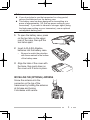
Installing/ Removing the (Optional) Battery Pack
1Match the guides of the
battery pack with the grooves
on the upper rear of the
transceiver, then firmly press
the battery pack in place.
2Lock the safety catch to
prevent accidentally releasing
the battery pack.
3To remove the battery pack,
lift the safety catch, press the
release latch, then pull the
battery pack away from the
transceiver.
2
1
3
Note:
◆ For battery pack charging procedures and useage, refer to the
battery charger Instruction Manual.
◆Before charging a battery pack that is attached to the
transceiver, ensure that the safety catch is firmly closed.
Installing/ Removing Alkaline Batteries
◆ Do not install batteries in a hazardous environment where
sparks could cause an explosion.
◆ Never discard batteries in fire; extremely high temperatures can
cause batteries to explode.
◆Do not short circuit the battery case terminals.
◆Do not use rechargeable batteries.
Note:
◆If you do not plan to use the transceiver for a long period,
remove the batteries from the battery case.
◆This battery case has been designed for transmitting at a
power of approximately 1 W (the low power setting on your
transceiver). If you want to transmit a stronger signal (using
the high power setting on your transceiver), use an optional
rechargeable battery pack.
1To open the battery case, press
on the two tabs on the upper
rear of the case, then pull the
two halvs apart.
2Insert 6 AA (LR6) Alkaline
batteries into the battery case.
•Be sure to match the polarities
with those marked in the bottom
of the battery case.
3 Align the tabs of the cover with
the base, then push down on
the cover until it locks in place.
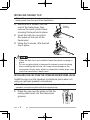
Installing the (Optional) Antenna
Screw the antenna into the
connector on the top of the
transceiver by holding the antenna
at its base and turning
it clockwise until secure.
Installing the Belt Clip
Note: When first installing the belt clip, you must remove the
battery pack from the rear of the transceiver.
1 Remove the 2 screws from the
rear of the transceiver, then
remove the small, plastic black
covering that was held in place.
2Insert the belt clip mount into
the space on the rear of the
transceiver.
3 Using the 2 screws, affix the belt
clip in place.
•
•
Plastic
covering
When the belt clip is not installed, leave the plastic covering in
place.
Do not use glue which is designed to prevent screw loosening
when installing the belt clip, as it may cause damage to the
transceiver. Acrylic ester, which is contained in these glues, may
crack the transceiver’s back panel.
Installing the Cap over the Speaker/ Microphone Jacks
Install the cap over the speaker/ microphone jacks when not
using an optional speaker/ microphone.
Note: To keep the transceiver water resistant, you must cover the
speaker/ microphone jacks with the supplied cap.
1Place the cap over the jacks so that the
locking tabs insert into the transceiver
grooves.
2 While holding the cap in place, push it
towards the bottom of the transceiver until
the tabs on the cap click into place.
•To remove the cap, hold the top of the cap
in place with your finger while inserting a 3
mm or smaller flat blade screwdriver under
the bottom of the cap. Slowly slide the
screwdriver in until its tip touches the tab
inside the cap, then gently pry the cap up
(handle of screwdriver moving away from the
transceiver) to remove the cap.
Installing the (Optional) Speaker/ Microphone
Note: The transceiver is not fully water resistant when using a
speaker/ microphone or headset.
1 Insert the speaker/ microphone plugs
into the speaker/ microphone jacks of the
transceiver.
2Place the locking bracket over the speaker/
microphone plugs so that the locking tabs
insert into the transceiver grooves.
3 While holding the locking bracket in
place, push it towards the bottom of the
transceiver until the tabs on the bracket
click into place.
•To remove the locking bracket, push the
bracket up from the base.
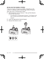
Installing the Channel Stopper
There are 3 types of stoppers available, depending on the
number of channels used (4 channel type: white, 8 channel
type: gray, and 12 channel type: black).
1Set the Selector knob to channel 1, then pull the Selector
knob off the transciever.
•If the Selector is not positioned at channel 1, the Selector knob
may not install correctly and the channel may be unable to be
changed.
2Insert the appropriate channel stopper.
3Reinsert the Selector knob.
3
1
2
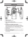
ORIENTATION
① Channel Selector
Rotate to select a channel.
② Power switch/ Volume control
Rotate to turn the transceiver ON/OFF and to adjust the
volume.
③ Transmit/ Receive/ Battery low indicator
If enabled by your dealer, lights red while transmitting,
green while receiving a call, and orange when receiving an
optional signaling call (2-tone, DTMF signaling, etc.). Blinks
red when the battery power is low while transmitting.
④ Auxiliary key
Press or hold to activate its programmable function {page 8}.
⑤ PTT (Push-To-Talk) switch
Press and hold this switch, then speak into the microphone
to call a station.
⑥ Side 1 key
Press or hold to activate its programmable function {page 8}.
⑦ Side 2 key
Press or hold to activate its programmable function {page 8}.
⑧ Speaker/ microphone jack
Connect a speaker/ microphone or headset here {page 5}.
Otherwise, keep the supplied cap in place.
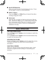
PROGRAMMABLE AUXILIARY FUNCTIONS
Your dealer can program the Auxiliary, Side 1, and Side 2
keys each with 1 or 2 of the following functions. Because each
key can be programmed with up to 2 functions, there are 2
methods of accessing the programmed functions. Functions
can be accessed by either pressing the key or by pressing and
holding the key. Ask your dealer for details.
n None
No function has been programmed.
n 2-tone
Press this key to send the 2-tone code assigned to it.
n Autodial
Press this key to call the DTMF number that has been
programmed onto your selected channel. Your dealer may
program different DTMF numbers on different channels.
n Battery Indicator
Press this key to announce the current battery energy level.
Battery level 4 (green LED) means the battery is full, level
3 (orange LED) is sufficient, level 2 (red LED) is low, and
level 1 (flashing red LED) is very low.
n Emergency
Press and hold this key to enter Emergency mode. When
the transceiver enters Emergency mode, it will change to
the Emergency channel and begin transmitting based on
your dealer settings.
Note: This function can be programmed only on the Auxiliary
key.
n Key Lock
Press this key to lock and unlock the transceiver keys.
While Key Lock is activated, you cannot use the Auxiliary,
Side 1, Side 2, and microphone PF keys.
Note: You can still use the following key functions when Key
Lock is activated: Emergency, Lone Worker, Monitor, Monitor
Momentary, Squelch Off, Squelch Off Momentary, Key Lock,
PTT + Autodial, PTT + 2-tone.
nLone Worker
Press this key to toggle the Lone Worker function ON or
OFF. If the transceiver is not operated for the
pre-programmed time, it will emit a Lone Worker tone.
Subsequently, if no operation is performed while the tone is
emitted, the transceiver will enter Emergency mode.
nLow Transmit Power
Press this key to change the transmit power on the current
channel to low power, to conserve battery energy.
n Monitor
Press this key to deactivate QT or DQT signaling. Press
this key again to return to normal operation.
n Monitor Momentary
Press and hold this key to deactivate QT or DQT signaling.
Release the key to return to normal operation.
n Paging
After selecting your desired FleetSync channel, press this
key to transmit your PTT List ID, to request a call.
n Priority Channel Select
Press this key to set the currently selected channel as
the Priority channel. During Scan, the transceiver will
automatically change to the Priority channel when a call is
received on that channel, even if a call is being received on
a normal channel.
n Scan
Press this key to toggle Scan ON and OFF. While
scanning, the transceiver checks for a signal on each
channel and only stops if a signal is present.
n Scan Temporary Delete
When scan pauses at an undesired channel, you can
temporarily remove that channel from the scanning
sequence by pressing this key.
n Scrambler
Press this key to toggle the Scrambler function ON and
OFF. The Scrambler allows you to hold conversations in
complete privacy by encrypting your transmitted signals.
n Squelch Off
Press this key to hear background noise. Press this key
again to return to normal operation.
10
n Squelch Off Momentary
Press and hold this key to hear background noise. Press
this key again to return to normal operation.
n Status 1/ Status 2
Press the Status 1 or Status 2 key to transmit the status
message assigned to them.
n Talk Around
Press this key to toggle the Talk Around function ON and
OFF. Talk Around allows you to communicate directly with
other transceivers without the use of a repeater, as long
they are not too far away or there are no geographical
obstacles in the way.
BASIC OPERATIONS
Switching Power ON/OFF
Turn the Power switch/ Volume control clockwise to switch the
transceiver ON.
Turn the Power switch/ Volume control counterclockwise fully
to switch the transceiver OFF.
Adjusting the Volume
Rotate the Power switch/ Volume control to adjust the volume.
Clockwise increases the volume and counterclockwise
decreases it.
Selecting a Channel
Select your desired channel using the Selector knob. Each
channel is programmed with settings for transmitting and
receiving.
11
Transmitting/ Receiving
1Select your desired channel.
2Press the key programmed as Monitor or Squelch Off to
check whether or not the channel is free.
•
If the channel is busy, wait until it becomes free.
•
For best sound quality, hold the transceiver approximately
1.5 inches (3 ~ 4 cm) from your mouth.
If signaling has been programmed on the channel, you will
hear a call only if the received signal matches your transceiver
settings.
3Press the PTT switch and speak into the microphone.
Release the PTT switch to receive.
•
SCAN
Scan monitors for signals on the transceiver channels. While
scanning, the transceiver checks for a signal on each channel
and only stops if a signal is present.
To begin scanning, press the key programmed as Scan.
•
When a signal is detected on a channel, Scan pauses at that
channel. The transceiver will remain on the busy channel until the
signal is no longer present, at which time Scan resumes.
To stop scanning, press the Scan key again.
Note: To use Scan, there must be at least 2 channels in the scan
sequence.
12
Priority Scan
If a Priority channel has been programmed, the transceiver
will automatically change to the Priority channel when a call is
received on that channel, even if a call is being received on a
normal channel.
If the Priority channel has been set as Operator Selectable by
your dealer, you can set a new channel as the Priority channel
by selecting your desired channel and pressing the key
programmed as Priority Channel Select.
Temporary Channel Lockout
During scan, you can temporarily remove specific channels
from the scanning sequence by pressing the key programmed
as Scan Temporary Delete while Scan is paused at the
undesired channel.
•
The channel is no longer scanned. However, when scanning is
ended and restarted, the channels are reset and deleted channels
will again be in the scanning sequence.
Scan Revert
The Scan Revert channel is the channel selected when you
press the PTT switch to transmit during scan. Your dealer can
program one of the following types of Scan Revert channels:
• Selected: The last channel selected before scan.
• Selected + Talkback: Same as “Selected”, plus you can
respond to calls on the channel at which scan is paused.
• Priority: The Priority channel.
• Priority + Talkback: Same as “Priority”, plus you can
respond to calls on the channel at which scan is paused.
• Last Called + Selected: The last channel on which you
receive a call or the last channel selected before scan,
whichever operation occured latest.
13
FleetSync: ALPHANUMERIC 2-WAY PAGING FUNCTION
FleetSync is an Alphanumeric 2-way Paging Function, and is a
protocol owned by Kenwood Corporation.
Note: If set up by your dealer, your transceiver may use the
MDC-1200 feature in place of FleetSync. MDC-1200 and FleetSync
cannot be operated simultaneously.
Selcall (Selective Calling)
A Selcall is a voice call to a station or group of stations.
■ Transmitting
1Select your desired FleetSync channel.
•Your dealer can program different ID codes on different
channels.
2Press the PTT switch and begin your conversation.
■Receiving
If enabled by your dealer, an alert tone will sound and the
LED will blink when a Selcall has been received.
To respond to the call, press the PTT switch and speak into
the microphone.
■ Identification Codes
An ID code is a combination of a 3-digit Fleet number and a
4-digit ID number. Each transceiver has its own ID.
Paging Call
1Select your desired FleetSync channel.
2Press the key programmed as Paging to transmit your PTT
List ID, to request a call.
14
Status Message
You can transmit pre-programmed Status messages by
pressing the keys programmed as Status 1 or Status 2.
Status messages are 2-digit codes ranging from 10 to 99
(80 ~ 99 are reserved for special messages).
VOICE OPERATED TRANSMISSION (VOX)
VOX operation allows you to transmit hands-free. This feature
can be activated or deactivated by your dealer.
VOX Gain Level
1Connect a headset to the transceiver.
2 With the transceiver power off, press and hold the Side 1
key for 2 seconds while turning the transceiver power ON.
•
The LED flashes red and green.
3Press the Side 1 key to increase the VOX Gain level, and
the Side 2 key to decrease the level.
•The VOX Gain can be adjusted from levels 1 to 10 and off.
4 While adjusting the level, speak into the headset
microphone to test the sensitivity level. (Your voice is not
trasmitted during this test procedure.)
•
When sound is recognized, the LED lights orange.
5Press the PTT switch to save the setting.
15
VOX Operation
1Connect a headset to the transceiver.
2To transmit, simply speak into the microphone.
•The transceiver recognizes sound levels depending on the
VOX Gain level. If it is too sensitive, it will transmit when there
is noise in the background. If it is not sensitive enough, it will
not pick up your voice when you begin speaking.
3 When you finish speaking, transmission ends.
BACKGROUND OPERATIONS
Your dealer can activate a variety of transceiver functions to
perform without any additional operation on your part.
Time-out Timer (TOT)
The Time-out Timer is used to prevent you from using a
channel for an extended duration. If you continuously transmit
for a preset time, the transceiver will stop transmitting and an
alert tone will sound. Release the PTT switch.
Battery Saver
The Battery Saver decreases the amount of power used when
a signal is not being received and no operations are being
performed.
Low Battery Warning
Low Battery Warning alerts you when the battery needs to be
recharged. Your dealer can set an alert tone to sound and
the LED indicator to blink red when the battery power is low.
Recharge or replace the battery pack at this time.
16
PTT ID
PTT ID is the transceiver unique ID code which is sent each
time the PTT switch is pressed and/or released.
Compander
If programmed by your dealer for a channel, the compander
will remove excessive noise from transmitted signals, to
provide higher clarity of signals.
Busy Channel Lockout (BCL)
If BCL is set up by your dealer, you will be unable to transmit if
the channel is already in use. Use a different channel or wait
until the channel becomes free.
Voice Announcement
When turning on the transceiver power and when changing the
channel, an audio voice will announce the selected channel
and the channel’s VOX and scrambler settings.
Quiet Talk (QT)/ Digital Quiet Talk (DQT)
Your dealer may have programmed QT or DQT signaling on
your transceiver channels. A QT tone/ DQT code is a
sub-audible tone/code which allows you to ignore (not hear)
calls from other parties who are using the same channel.
Stun Code
This function is used when a transceiver is stolen or lost.
When the transceiver receives a call containing a stun code,
the transceiver becomes disabled. The stun code is cancelled
when the transceiver receives a call with a revive code.
17
Optional Signaling
Your dealer may also program several types of optional
signaling for your transceiver channels.
2-tone Signaling: 2-tone Signaling opens the squelch only when
your transceiver receives a call containing matching 2 tones.
DTMF Signaling: DTMF Signaling opens the squelch only
when the transceiver receives a call containing a matching
DTMF code.
FleetSync Signaling: Refer to “SELCALL (SELECTIVE
CALLING)” on page 14.
MDC-1200: MDC-1200 is a data system using Audio
Frequency Shift Keying (AFSK).
18