1
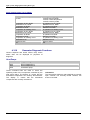
Document 1544-1 ~ 20/06/2012
FR
EN
Air to water heat pump
Split System (single phase type)
Hydraulic unit
Outdoor unit
WS *G140DC6
WO *G112LCT
WO *G140LCT
Split System (3-phase type)
Hydraulic unit
Outdoor unit
WS *K160DC9
WO *K112LCT
WO *K140LCT
WO *K160LCT
Maintenance
Document
Intended for
professional use
Fujitsu General (Euro) GmbH
Werftstrasse 20
40549 Düsseldorf - Germany
Subject to change without notice
Non contractual
document
20/06/2012
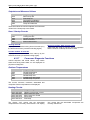
Contents
1
Control and test ..............................................................................................................5
1.1
2
2.1.1
2.1.2
2.2
2.2.1
2.2.2
2.3
2.3.1
2.3.2
2.4
Fault List.........................................6
Hydraulic Unit Fault..........................6
Outdoor Unit Fault............................8
Outdoor Unit Clearing.....................9
Failures with Error Code ..................9
Failures With No Error Code..........31
Sensor Values ..............................35
Outdoor Unit Temperature Sensors35
Hydraulic Unit Temperature Sensors35
Service parts information..............36
3.1.1
3.1.2
3.1.3
2.4.1 Service parts information 1 :
Compressor ................................................ 36
2.4.2 Service parts information 2 : Inverter
compressor................................................. 37
2.4.3 Service parts information 3 : Outdoor
unit electronic expansion valve (EEV, EEV(INJ))
38
2.4.4 Service parts information 4 : Outdoor
unit solenoid valve (SV).............................. 39
2.5
Operating Limits...........................40
Hydraulic System ...........................41
Electrical System ...........................42
Refrigeration System .....................43
3.2
3.3
3.4
Compressor Operating Checks....45
Refrigeration Circuit Leak Test ....45
Troubleshooting ...........................45
Control Settings............................................................................................................46
4.1
4.2
4.3
General.........................................46
Function Table..............................47
Adjustment Function Details.........53
4.3.1 Date and Time Functions...............53
4.3.2 User Interface Functions................53
4.3.3 Time Program Functions (heating circuit
1 & 2, DHW, cooling) ..................................54
4.3.4 Heating Circuit 1 & 2 Functions .....55
4.3.5 Cooling Circuit 1 Functions ............62
4.3.6 DHW Functions..............................68
4.3.7 Swimming Pool Functions..............71
5
Sensor and Input Test Mode..........5
Failures..........................................................................................................................41
3.1
Hydraulic, Electric and Refrigeration
Systems ...................................................41
4
1.2
Faults ...............................................................................................................................6
2.1
3
Control of Electric Backups ............5
4.3.8 Heat Pump Functions .................... 71
4.3.9 Supplementary source................... 73
4.3.10 DHW Tank Functions .................... 74
4.3.11 Configuration Functions................. 76
4.3.12 Error Functions .............................. 78
4.3.13 Maintenance / Special Operating Mode
Functions .................................................... 80
4.3.14 Input / Output Testing Functions ... 82
4.3.15 Status Functions............................ 83
4.3.16 Generator Diagnosis Functions..... 88
4.3.17 Consumer Diagnosis Functions .... 89
Annual Maintenance Services .....................................................................................92
5.1
5.2
Hydraulic Circuit ...........................92
Outdoor unit..................................92
5.3
5.4
Electrical ......................................92
Operating checks .........................92
20/06/2012
Split system (Single phase and 3-phase type)
6
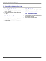
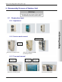
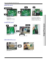
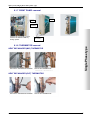
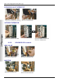
Disassembly Process of Outdoor Unit........................................................................93
6.1
Single phase type ........................ 93
6.1.1 Appearance................................... 93
6.1.2 Service panel removal................... 93
6.1.3 Top panel removal ........................ 93
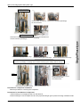
6.1.4 MAIN PCB, FILTER PCB, and
INDICATOR PCB removal ......................... 94
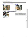
6.1.5 FAN MOTOR removal................... 96
6.1.6 VALVE COVER removal............... 96
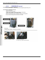
6.1.7 RIGHT PANEL removal ................ 97
6.1.8 THERMISTOR removal................. 97
6.1.9 SOLENOID COIL removal ............ 98
6.1.10 EEV COIL removal........................ 99
6.1.11 PRESSURE SENSOR removal .... 99
6.1.12 COMPRESSOR removal .............. 99
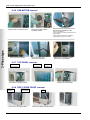
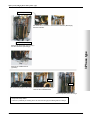
6.2
6.2.1
6.2.2
4
3-phase type ................................ 99
Appearance................................... 99
Service panel removal................... 99
6.2.3 Insulation sheet removal................99
6.2.4 Main PCB removal.........................99
6.2.5 INVERTER, PFC, FILTER, and
CAPACITOR PCB removal ........................99
6.2.6 FAN MOTOR removal ...................99
6.2.7 TOP PANEL removal.....................99
6.2.8 PIPE COVER FRONT removal .....99
6.2.9 RIGHT PANEL removal.................99
6.2.10 REACTOR removal .......................99
6.2.11 THERMISTOR removal .................99
6.2.12 SOLENOID COIL removal.............99
6.2.13 EEV COIL removal ........................99
6.2.14 PRESSURE SENSOR removal.....99
6.2.15 COMPRESSOR removal...............99
6.3
Precautions for exchange of
refrigerant-cycle-parts ............................. 99
Maintenance Document 1544-1
Split system (Single phase and 3-phase type)
1 Control and test
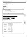
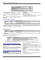
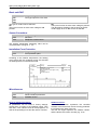
1.1
Control of Electric Backups
EX 1
Load-shedding (EJP)
H 33
Outdoor
Unit Fault
(370)
0V
OFF
ON (1)
ON (2)
ON (2)
ON (2)
ON
ON
ON
ON
ON
EJP lock signal (l 2920)
HEAT PUMP
DHW auxiliary
1st stage elec. auxiliary
2nd stage elec. auxiliary
Boiler backup
230 V
230 V
"released"
"locked"
OFF
OFF
OFF
OFF
ON
ON
OFF
OFF
OFF
ON
EX 2
Off-peak/peak
hours
0V
230 V
EX 3
External fault
(369)
0V
230 V
ON
ON
ON
ON
ON
ON
ON
ON
ON
ON
ON
OFF
ON
ON
ON
OFF
OFF
OFF
OFF
OFF
(1) subject to authorization by EX2
(2) provided the outdoor temperature is less than the setting on "2884 or 3700" (+2° from the beginning)
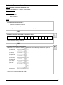
1.2
LINE
7700
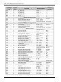
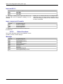
Sensor and Input Test Mode
SENSOR
INPUT
OUTPUT
QX
Relay test
WATERSTAGE
7710
UX1
Output test
7712
UX1
PWM-Signal
7722
DO2
Cooling mode
7723
D3
Heat pump
7724
UX3
Output test ("Inverter" command)
7725
UX3
Voltage signal (Ux3)
7820
BX1
Sensor temp (HP flow temperature)
7821
BX2
Sensor temp (HP return temperature)
7822
BX3
Sensor temp (DHW temperature)
7823
BX4
Sensor temp (Outside temperature)
7911
EX1
Input (Power shedding, EJP)
7912
EX2
Input (Tariffs day/night)
7913
EX3
Input (External fault)
7973
BX31
Sensor temp (Mixing circuit temp.)
7976
BX34
Sensor temp (Swimming pool exchanger temperature)
7996
H33
Contact state
Maintenance Document 1544-1
5
Split system (Single phase and 3-phase type)
2 Faults
2.1
Fault List
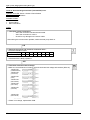
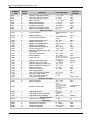
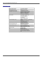
2.1.1 Hydraulic Unit Fault
Faults which occur on the Hydraulic Unit are shown
by the symbol . Press the info key for details on the
cause of the fault. The following information is
displayed:
Description of the error
Location of the error (sensor or contact)
Reset. Depending on its type, the fault can be
manually or automatically deleted:
No.: Designation of error
10: Outdoor sensor
33: Flow sensor HP
44: Return sensor HP
50: DHW sensor 1
60: Room sensor 1
65: Room sensor 2
105: Maintenance message
121: Flow temp HC1 (too low)
122: Flow temp HC2 (too low)
127: Legionella temp
369: External fault (safety component)
370: Thermodynamic source*
Manual delete: the text displayed when pressing
the info key shows "reset ?". Press OK once, the
yes flashes; press again to confirm deletion of the
fault.
Faults whose deletion is automatic are
automatically reset.
Heat pump op: shows whether or not the heat pump
operates despite the fault.
Location
(connection)
X86
X70
X70
X84
the polarity of the
room sensor is not
respected.
No connection
Reset
Manual
No
No
No
No
No
No
No
No
No
No
Auto
No
No
No
No
No
No
No
No
No
No
HP op
No
No
Yes
Yes
Yes
Yes
Yes
Yes
Yes
Yes
Yes
Yes
No
No
-
-
No
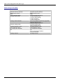
* A fault in the outdoor unit is indicated by LED located on the Hydraulic Unit interface board.
LED display
LED 2 (green)
1 Flash
4 Flashes
4 Flashes
6 Flashes
6 Flashes
7 Flashes
7 Flashes
7 Flashes
LED 1(red)
1 Flash
1 Flash
2 Flashes
3 Flashes
4 Flashes
1 Flash
2 Flashes
3 Flashes
7 Flashes
7 Flashes
7 Flashes
8 Flashes
8 Flashes
9 Flashes
9 Flashes
4 Flashes
7 Flashes
8 Flashes
4 Flashes
6 Flashes
4 Flashes
5 Flashes
9 Flashes
7 Flashes
10 Flashes
1 Flash
10 Flashes
3 Flashes
10 Flashes
5 Flashes
Continuous flashing (1 sec ON / 1 sec OFF)
6
Fault description
Communication error between Hydraulic Unit and Outdoor unit.
Heat pump capacity signal error (Open or short).
Hydraulic Unit heat-exchange thermistor Error.
Inverter error.
Active filter error.
Discharge thermistor error.
Compressor thermistor error.
Heat-exchange thermistor (outlet) error.
Heat-exchange thermistor (intermediate) error.
Outdoor thermistor error.
Heat sink thermistor error.
Expansion valve thermistor error.
Current sensor error.
Pressure sensor error.
Current trip.
Detection of compressor position error.
Compressor start up error.
Outdoor unit fan motor error.
Discharge temperature protection.
Compressor temperature protection.
Low pressure abnormal.
Pump down operation.
Maintenance Document 1544-1
Split system (Single phase and 3-phase type)
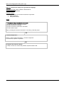
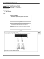
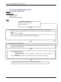
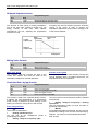
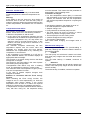
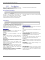
Faults external to the heat pump
Any safety device (e.g. thermostat pressure switch)
wired to input Ex3 (E20) allows external problems to
be reported and the heat pump to be immediately
stopped. For example, a safety thermostat on the
heating floor can be wired to input Ex3 (E20) to avoid
excessively high temperatures in the floor.
Figure 1: Typical Wiring of External Devices
Maintenance Document 1544-1
7
Split system (Single phase and 3-phase type)
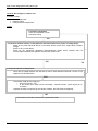
2.1.2 Outdoor Unit Fault
When the system is switched back on after a power
outage, the Hydraulic Unit may display fault 370 for a
few tens of seconds. This is not a serious problem. It
simply means that the outdoor unit is running its
tests. Once the tests have been completed, the fault
should disappear.
If it doesn't, if a fault has occurred on the outdoor unit
as indicated by the Hydraulic Unit, you must remove
the front (right-hand) facing from the outdoor unit.
Faults are coded by LED flashes. Error messages are
listed in the table below:
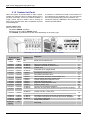
On the outdoor unit
When an error occurs:
- The diode “ERROR” (2) blinks
Press once on the switch “ENTER” (SW4)
- The “ERROR” (2) diode blinks several times depending on the error’s type
LED display on the outdoor unit (single phase and 3-phase)
LED display
Hydraulic Unit
Outdoor unit
Green
Red
Off
1 flash
1 flash
1 flash
4 flashes
1 flash
22 flashes
4 flashes 2 flashes 22 flashes
6 flashes 3 flashes 18 flashes
6 flashes
4 flashes
19 flashes
7 flashes
7 flashes
1 flash
2 flashes
7 flashes
3 flashes
7 flashes
7 flashes
7 flashes
8 flashes
9 flashes
4 flashes
7 flashes
8 flashes
6 flashes
4 flashes
9 flashes
5 flashes
9 flashes
7 flashes
2 flashes
8 flashes
5 flashes
4 flashes
7 flashes
9 flashes
6 flashes
3 flashes
13 flashes
14 flashes
15 flashes
16 flashes
17 flashes
11 flashes
12 flashes
20 flashes
10 flashes 1 flash
10 flashes 3 flashes
10 flashes 5 flashes
Continuous flashing
Continuous
Off
lighting
8
Diagnosis
Clear
Serial reverse transfer error.
Serial forward transfer error.
Heat pump capacity signal error
Hydraulic Unit Heat ex. Sensor error
Inverter error.
Active filter error (single phase)
P.F.C. error (3-phase)
Discharge thermistor error.
Compressor thermistor error.
Heat-exchange thermistor (intermediate) error.
Heat-exchange thermistor (outlet) error.
Outdoor temperature thermistor error.
Heat sink thermistor error.
Expansion valve thermistor error.
Pressure sensor error.
Current trip (permanent stoppage).
Detection of compressor position error (permanent stoppage).
Compressor start up error (permanent stoppage).
Outdoor unit fan 1 motor error.
Outdoor unit fan 2 motor error.
Discharge temperature protection (permanent stoppage).
Compressor temperature protection (permanent stoppage).
Low pressure abnormal.
Pump down operation.
1
2
4
5
20
21
27
7
11
12
8
9
10
14
24
15
33
17
18
22
25
26
Defrosting.
Maintenance Document 1544-1
Split system (Single phase and 3-phase type)
2.2
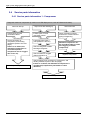
Outdoor Unit Clearing
This section describes the techniques which can be used to identify the failure.
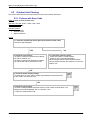
2.2.1 Failures with Error Code
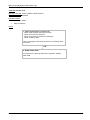
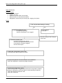
Clear 1: Serial reverse transfer error
Hydraulic Unit LED: Green 1 flash / Red 1 flash
Outdoor Unit LED: Off
Probable causes:
Misconnection.
External cause.
Main PCB failure.
Check:
1-1. Stop the system and start it again (disconnection time 1min):
Is the error still displayed?
YES
NO
2. Check the connections:
- Check the connection between the hydraulic
unit and the outdoor unit.
- Check the connections between the outdoor
unit main board and the active filter board.
1-2. Check for external causes:
- Check the system's overall isolation.
- Check for any equipment generating
electromagnetic waves which interfere with the
communication between the hydraulic unit and the
outdoor unit.
OK
3. Check the power supply voltage:
- Check that an AC 198 – 264 V voltage exists between terminals N and L
on the outdoor unit terminal block.
OK
4. Check the serial signal:
- Check the voltage between terminals 2 and 3 of the outdoor terminal block. The
voltage must fluctuate between AC 70 V and AC 130 V.
- If it doesn't, replace Main PCB.
Maintenance Document 1544-1
9
Split system (Single phase and 3-phase type)
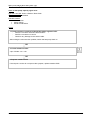
Clear 2: Serial forward transfer error
Hydraulic Unit LED: Green 1 flash / Red 1 flash
Outdoor Unit LED: 1 flash
Probable causes:
Misconnection.
External cause.
Interface PCB failure.
Check:
1-1. Stop the system and start it again (disconnection time 1min):
Is the error still displayed?
YES
NO
2. Check the connections:
- Check the connection between the hydraulic
unit and the outdoor unit.
- Check the connections between the outdoor
unit main board and the active filter board.
1-2. Check for external causes:
- Check the system's overall isolation.
- Check for any equipment generating
electromagnetic waves which interfere with the
communication between the hydraulic unit and the
outdoor unit.
OK
3. Check the power supply voltage:
- Check that an AC 198 – 264 V voltage exists between terminals N and L
on the outdoor unit terminal block.
OK
4. Check the serial signal:
- Check the voltage between terminals 2 and 3 of the outdoor terminal block. The
voltage must fluctuate between AC 70 V and AC 130 V.
- If it doesn't, replace Interface PCB.
10
Maintenance Document 1544-1
Split system (Single phase and 3-phase type)
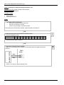
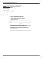
Clear 4: Heat pump capacity signal error
Hydraulic Unit LED: Green 4 flashes / Red 1 flash
Outdoor Unit LED: 22 flashes
Probable causes:
Misconnection.
Sensor failure.
Interface PCB failure.
Check:
1. Check connection interface PCB and Heat pump regulator PCB:
- See if the connector has been disconnected.
- See if the connection is correct.
- Check for any damage on the sensor cable.
After solving the misconnection problem, switch the heat pump back on.
OK
2. Check resistance value:
3 pin of CN22 – M < 10Ω
OK
3. Replace interface PCB:
If check point 1 and 2 do not improve the symptom, replace Interface PCB.
Maintenance Document 1544-1
11
Split system (Single phase and 3-phase type)
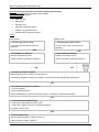
Clear 5: Hydraulic Unit Heat exchanger thermistor error
Hydraulic Unit LED: Green 4 flashes / Red 2 flashes
Outdoor Unit LED: 22 flashes
Probable causes:
Misconnection.
Sensor failure.
Interface PCB failure.
Check:
1. Check the sensor connection:
- See if the connector has been removed
- See if the connection is correct
- Check for any damage on the sensor cable.
After solving the misconnection problem, switch the heat pump back on.
OK
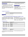
2. Remove the sensor and check its resistance value :
- Check the resistance value.
Temperature (°C) 0
5
10
15
20
25
30
35
40
45
50
Resistance (k) 176 134 103 80,3 62,9 49,7 39,6 31,7 25,6 20,8 17,1
- If the thermistor is faulty, replace it.
OK
3. Check the electronic board voltage:
- Make sure circuit diagram of hydraulic unit and check terminal voltage at thermistor
(DC5.0V)
Black
Gray
Gray
- If there is no voltage, replace Interface PCB.
12
Maintenance Document 1544-1
Split system (Single phase and 3-phase type)
Clear 7: Discharge thermistor error
Hydraulic Unit LED: Green 7 flashes / Red 1 flash
Outdoor Unit LED: 2 flashes
Probable causes:
Misconnection.
Sensor failure.
Main PCB failure.
Check:
1. Check the sensor connection:
- See if the connector has been disconnected.
- See if the connection is correct.
- Check for any damage on the sensor cable.
After solving the misconnection problem, switch the heat pump back on.
OK
2. Remove the sensor and check its resistance value:
- Check the resistance value
Temperature (°C)
0
5
10 15 20 30
40
50
Resistance (kΩ)
168 130 101 79 63 40 26,3 17,8
Temperature (°C)
Resistance (kΩ)
60
70
12,3 8,7
80
6,3
90
4,6
100 120
3,4
2
- If the thermistor is faulty, replace it.
OK
3. Check the electronic board voltage:
Make sure circuit diagram of outdoor unit and check terminal voltage at thermistor (DC5.0V)
THERMISTOR
(COMPRESSOR)
THERMISTOR
(OUTDOOR)
THERMISTOR
(PIPE)
THERMISTOR
(DISCHARGE)
THERMISTOR
(HEAT SINK)
THERMISTOR
(PIPE MID)
THERMISTOR
(EXPANSION)
- If there is no voltage, replace Main PCB.
Maintenance Document 1544-1
13
Split system (Single phase and 3-phase type)
Clear 8: Heat-exchange thermistor (outlet) error :
Hydraulic Unit LED: Green 7 flashes / Red 3 flashes
Outdoor Unit LED: 4 flashes
Probable causes:
Misconnection.
Sensor fault.
Main PCB failure.
Check:
1. Check the sensor connection:
- See if the connector has been disconnected.
- See if the connection is correct.
- Check for any damage on the sensor cable.
After solving the misconnection problem, switch the heat pump back on.
OK
2. Remove the sensor and check its resistance value :
- Check the resistancer value
Temperature (°C) -10 -5
0
10
15
20
25
30
Resistance (kΩ)
27,5 20,9 16,1 12,4 9,73 7,67 6,1 3,95
- If the thermistor is faulty, replace it.
OK
3. Check the electronic board voltage:
- Make sure circuit diagram of outdoor unit and check terminal voltage at thermistor
(DC5.0V)
THERMISTOR
(COMPRESSOR)
THERMISTOR
(OUTDOOR)
THERMISTOR
(PIPE)
THERMISTOR
(DISCHARGE)
THERMISTOR
(HEAT SINK)
THERMISTOR
(PIPE MID)
THERMISTOR
(EXPANSION)
- If there is no voltage, replace Main PCB.
14
Maintenance Document 1544-1
Split system (Single phase and 3-phase type)
Clear 9: Outdoor temperature thermistor error
Hydraulic Unit LED: Green 7 flashes / Red 4 flashes
Outdoor Unit LED: 7 flashes
Probable causes:
Misconnection.
Sensor failure.
Main PCB failure.
Check:
1. Check the sensor connection :
- See if the connector has been disconnected.
- See if the connection is correct.
- Check for any damage on the sensor cable.
After solving the misconnection problem, switch the heat pump back on.
OK
2. Remove the sensor and check its resistance value :
- Check the resistance value.
Temperature (°C) -20 -10 -5
0
5
10
15
20
30
40
50
60
70
Resistance (kΩ)
115 62,3 46,6 35,2 26,9 20,7 16,1 12,6 7,97 5,18 3,45 2,36 1,65
- If the thermistor is faulty, replace it.
OK
3. Check the electronic board voltage:
- Make sure circuit diagram of outdoor unit and check terminal voltage at thermistor (DC5.0V)
THERMISTOR
(COMPRESSOR)
THERMISTOR
(OUTDOOR)
THERMISTOR
(PIPE)
THERMISTOR
(DISCHARGE)
THERMISTOR
(HEAT SINK)
THERMISTOR
(PIPE MID)
THERMISTOR
(EXPANSION)
- If there is no voltage, replace Main PCB.
Maintenance Document 1544-1
15
Split system (Single phase and 3-phase type)
Clear 10: Heat Sink Thermistor error
Hydraulic Unit LED: Green 7 flashes / Red 7 flashes
Outdoor Unit LED: 9 flashes
Probable causes:
Misconnection.
Sensor failure.
Main PCB failure.
Check:
1. Check the sensor connection :
- See if the connector has been disconnected.
- See if the connection is correct.
- Check for any damage on the sensor cable.
After solving the misconnection problem, switch the heat pump back on.
OK
2. Remove the sensor and check its resistance value :
- Check the resistance value.
Temperature (°C)
0
5
10
15
20
30
40
50
Resistance (kΩ)
15,8 12,2 9,5 7,5 5,9 3,78 2,50 1,69
Temperature (°C)
Resistance (kΩ)
60
70
80
90 100 120
1,17 0,83 0,6 0,44 0,33 0,19
- If the thermistor is faulty, replace it.
OK
3. Check the electronic board voltage:
- Make sure circuit diagram of outdoor unit and check terminal voltage at thermistor (DC5.0V)
THERMISTOR
(COMPRESSOR)
THERMISTOR
(OUTDOOR)
THERMISTOR
(PIPE)
THERMISTOR
(DISCHARGE)
THERMISTOR
(HEAT SINK)
THERMISTOR
(PIPE MID)
THERMISTOR
(EXPANSION)
- If there is no voltage, replace Main PCB.
16
Maintenance Document 1544-1
Split system (Single phase and 3-phase type)
Clear 11: Compressor thermistor error
Hydraulic Unit LED: Green 7 flashes / Red 2 flashes
Outdoor Unit LED: 8 flashes
Probable causes:
Misconnection.
Sensor failure.
Main PCB failure.
Check:
1. Check the sensor connection:
- See if the connector has been removed
- See if the connection is correct
- Check for any damage on the sensor cable.
After solving the misconnection problem, switch the heat pump back on.
OK
2. Remove the sensor and check its resistance value :
- Check the resistance value.
Temperature (°C) 0
5
10 15 20 30
40
50
Resistance (kΩ) 168 130 101 79 63 40 26,3 17,8
Temperature (°C) 60
70
Resistance (kΩ) 12,3 8,7
80
6,3
90
4,6
100 120
3,4
2
- If the thermistor is faulty, replace it.
OK
3. Check the electronic board voltage:
- Make sure circuit diagram of outdoor unit and check terminal voltage at thermistor (DC5.0V)
THERMISTOR
(COMPRESSOR)
THERMISTOR
(OUTDOOR)
THERMISTOR
(PIPE)
THERMISTOR
(DISCHARGE)
THERMISTOR
(HEAT SINK)
THERMISTOR
(PIPE MID)
THERMISTOR
(EXPANSION)
- If there is no voltage, replace Main PCB.
Maintenance Document 1544-1
17
Split system (Single phase and 3-phase type)
Clear 12: Heat-exchange thermistor (intermediate) error
Hydraulic Unit LED: Green 7 flashes / Red 3 flashes
Outdoor Unit LED: 5 flashes
Probable causes:
Misconnection.
Sensor failure.
Main PCB failure.
Check:
1. Check the sensor connection:
- See if the connector has been disconnected.
- See if the connection is correct.
- Check for any damage on the sensor cable.
After solving the misconnection problem, switch the heat pump back on.
OK
2. Remove the sensor and check its resistance value :
- Check the resistance value
Temperature (°C) -10 -5
0
10
15
20
25
30
Resistance (kΩ)
27,5 20,9 16,1 12,4 9,73 7,67 6,10 3,95
- If the thermistor is faulty, replace it.
OK
3. Check the electronic board voltage:
- Make sure circuit diagram of outdoor unit and check terminal voltage at thermistor (DC5.0V)
THERMISTOR
(COMPRESSOR)
THERMISTOR
(OUTDOOR)
THERMISTOR
(PIPE)
THERMISTOR
(DISCHARGE)
THERMISTOR
(HEAT SINK)
THERMISTOR
(PIPE MID)
THERMISTOR
(EXPANSION)
- If there is no voltage, replace Main PCB.
18
Maintenance Document 1544-1
Split system (Single phase and 3-phase type)
Clear 14: Expansion valve thermistor error
Hydraulic Unit LED: Green 7 flashes / Red 8 flashes
Outdoor Unit LED: 6 flashes
Probable causes:
Misconnection.
Sensor failure.
Main PCB failure.
Check:
1. Check the sensor connection:
- See if the connector has been removed
- See if the connection is correct
- Check for any damage on the sensor cable.
After solving the misconnection problem, switch the heat pump back on.
OK
2. Remove the sensor and check its resistance value :
- Check the resistance value.
Temperature (°C) 0
5
10 15 20 30
40
50
Resistance (kΩ) 168 130 101 79 63 40 26,3 17,8
Temperature (°C) 60
70
Resistance (kΩ) 12,3 8,7
80
6,3
90
4,6
100 120
3,4
2
- If the thermistor is faulty, replace it.
OK
3. Check the electronic board voltage:
- Make sure circuit diagram of outdoor unit and check terminal voltage at thermistor (DC5.0V)
THERMISTOR
(COMPRESSOR)
THERMISTOR
(OUTDOOR)
THERMISTOR
(PIPE)
THERMISTOR
(DISCHARGE)
THERMISTOR
(HEAT SINK)
THERMISTOR
(PIPE MID)
THERMISTOR
(EXPANSION)
- If there is no voltage, replace Main PCB.
Maintenance Document 1544-1
19
Split system (Single phase and 3-phase type)
Clear 15: Current trip (permanent stoppage)
Hydraulic Unit LED: Green 9 flashes / Red 4 flashes
Outdoor Unit LED: 13 flashes
Probable causes:
Connection failure.
Outdoor Heat Exchanger clogged.
Outdoor Fan operation failure.
Compressor failure.
Main PCB failure.
Check:
1. Check connections condition in control unit:
- Check if the terminal connection is loose.
- Check if connector is removed.
- Check if connector is erroneous connection.
- Check if cable is open.
Upon correcting the removed connector or mis-wiring, reset the power.
OK
2. Check Outdoor Heat Exchanger:
- Is there any obstructing the air flow route?
- Is there any clogging of outdoor unit Heat Exchanger?
If clogged, clear the clog.
OK
3. Check Outdoor Fan:
- Check Outdoor Fan Motor. (Refer to Clear 18)
If the Fan Motor is failure, replace it.
OK
4. Check Compressor:
Refer to “Service parts information 2 : Inverter compressor
If it is abnormal, replace compressor.
OK
5. Replace Inverter PCB:
If Check Point 1 ~ 4 do not improve the symptom, replace Inverter PCB.
20
Maintenance Document 1544-1
Split system (Single phase and 3-phase type)
Clear 17: Compressor startup error (permanent stoppage)
Hydraulic Unit LED: Green 9 flashes / Red 5 flashes
Outdoor Unit LED: 15 flashes
Probable causes:
Misconnection of the various electrical components.
Main PCB failure.
Compressor failure.
Check:
1. Check connections condition in control unit:
- Check if the terminal connection is loose.
- Check if connector is removed.
- Check if connector is erroneous connection.
- Check if cable is open.
Upon correcting the removed connector or mis-wiring, reset the power.
OK
2. Check Compressor:
Refer to “Service parts information 2 : Inverter compressor
If it is abnormal, replace compressor.
OK
3. Replace the electronic board :
- If steps 1 and 2 do not solve the problem, replace Inverter PCB.
Maintenance Document 1544-1
21
Split system (Single phase and 3-phase type)
Clear 18: Fan motor error (permanent stoppage)
Hydraulic Unit LED: Green 9 flashes / Red 7 flashes
Outdoor Unit LED: 16 flashes (fan 1), 17 flashes (fan 2)
Probable causes:
Fan motor failure.
Motor protection.
Main PCB failure.
Check:
1. Check fan rotation:
- Switch off the heat pump and rotate the fan manually.
- If the fan or bearings are faulty, replace them.
OK
2. Check the ambient temperature around the motor:
- Check excessively high temperature around the fan.
Wait until the temperature comes down again and switch the
fan back on.
OK
3. Check the main board output voltage:
- On the outdoor unit, check the output voltage (DC) of the following connectors:
CN802
Voltage
300 390V
15 ±2V
FAN MOTOR 2
(LOWER)
FAN MOTOR 1
(UPPER)
Terminals
1 (red)/ 3 (black)
4 (white)/3 (black)
CN803
If the voltage is incorrect, replace Main PCB.
22
Maintenance Document 1544-1
Split system (Single phase and 3-phase type)
Clear 20: Inverter error
Hydraulic Unit LED: Green 6 flashes / Red 3 flashes
Outdoor Unit LED: 18 flashes
Probable causes:
Connection failure.
Main PCB failure.
Check:
1. Check connections in control unit:
- Check if the terminal connection is loose.
- Check if connector is removed.
- Check if connector is erroneous connection.
- Check if cable is open.
Upon correcting the removed connector or mis-wiring, reset
the power.
OK
2. Replace Main PCB :
If Check Point 1 does not improve the symptom, replace
Main PCB.
Maintenance Document 1544-1
23
Split system (Single phase and 3-phase type)
Clear 21: active filter error (only for single phase type)
Hydraulic Unit LED: Green 6 flashes / Red 4 flashes
Outdoor Unit LED: 19 flashes
Probable causes:
Connection failure.
Active filter module failure.
Main PCB failure.
Check:
1. Check connections in control unit:
- Check if the terminal connection is loose.
- Check if connector is removed.
- Check if connector is erroneous connection.
- Check if cable is open.
Upon correcting the removed connector or mis-wiring, reset
the power.
OK
2. Replace Active Filter Module and Main PCB :
If Check Point 1 does not improve the symptom, replace
Main PCB and Active Filter Module and execute the
checkoperation again.
24
Maintenance Document 1544-1
Split system (Single phase and 3-phase type)
Clear 22: Discharge temperature protection (permanent stoppage)
Hydraulic Unit LED: Green 10 flashes / Red 1 flashes
Outdoor Unit LED: 11 flashes
Probable causes:
Valve is close.
EEV failure.
Gas leak, less.
Discharge Thermistor failure.
Outdoor Fan operation failure.
Outdoor Heat Exchanger clogged.
Check:
Cooling mode
Heating mode
1. Check if gas valve is open:
1. Check if liquid valve is open:
If it is not open, open it and check the
operation.
If it is not open, open it and check the
operation.
OK
OK
2. Check EEV and Strainer:
Are EEV and Strainer open?
2. Check EEV and Strainer:
Are EEV and Strainer open?
If EEV or Strainer is defective, replace it.
If EEV or Strainer is defective, replace it.
OK
OK
3. Check if gas leak or less gas:
Measure gas pressure, if there is a leak, correct it.
If recharging refrigerant, make sure to perform vacuuming and recharge the specified amount.
OK
4. Check Discharge Pipe Thermistor:
- Is it on the holder?
- Is there a cable pinched?
Check characteristics of thermistor (Refer to Clear 7), If defective, replace the thermistor
OK
5. Check Outdoor Heat Exchanger:
- Is there any obstructing the air flow route?
- Is there any clogging of outdoor unit Heat Exchanger?
If clogged, clear the clog.
OK
6. Check Outdoor Fan:
Check Outdoor Fan Motor. (Refer to Clear 18)
If the Fan Motor is failure, replace it.
Maintenance Document 1544-1
25
Split system (Single phase and 3-phase type)
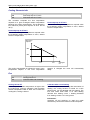
Clear 24: Pressure sensor error
Hydraulic Unit LED: Green 8 flashes / Red 6 flashes
Outdoor Unit LED: 3 flashes
Probable causes:
Connector connection failure.
Pressure Sensor failure.
Main PCB failure.
Check:
1. Check connection of the Pressure Sensor:
- Check if the terminal connection is loose.
- Check if connector is removed.
- Check if connector is erroneous connection.
- Check if cable is open.
Upon correcting the removed connector or mis-wiring, reset the power.
OK
2. Check output voltage of Main PCB :
Check voltage of Main PCB (Measure at Main PCB side connector)
1 pin(Red) - 3 pin(Black) DC5V +/- 5%
PRESSURE SENSOR
If the voltage is not correct, replace Main PCB.
OK
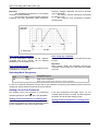
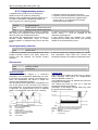
3. Check output voltage of Pressure Sensor
Check voltage of Main PCB (Measure at Main PCB side connector)
2 pin(White) - 3 pIn(Black) Voltage is refer to the following graph.
Voltage [V]
Pressure [MPa]
If the voltage is not correct, replace Presure Sensor.
26
Maintenance Document 1544-1
Split system (Single phase and 3-phase type)
Clear 25: Compressor temperature protection (permanent stoppage)
Hydraulic Unit LED: Green 10 flashes / Red 3 flashes
Outdoor Unit LED: 12 flashes
Probable causes:
Valve is close.
EEV failure.
Gas leak, less.
Compressor Thermistor failure.
Outdoor Fan operation failure.
Outdoor Heat Exchanger clogged.
Check:
Cooling mode
Heating mode
1. Check if gas valve is open:
1. Check if liquid valve is open:
If it is not open, open it and check the
operation.
If it is not open, open it and check the
operation.
OK
OK
2. Check EEV and Strainer:
Are EEV and Strainer open?
2. Check EEV and Strainer:
Are EEV and Strainer open?
If EEV or Strainer is defective, replace it.
If EEV or Strainer is defective, replace it.
OK
OK
3. Check if gas leak or less gas:
Measure gas pressure, if there is a leak, correct it.
If recharging refrigerant, make sure to perform vacuuming and recharge the specified amount.
OK
4. Check compressor temperature Thermistor:
- Is it on the holder?
- Is there a cable pinched?
Check characteristics of thermistor (Refer to Clear 11), If defective, replace the thermistor
OK
5. Check Outdoor Heat Exchanger:
- Is there any obstructing the air flow route?
- Is there any clogging of outdoor unit Heat Exchanger?
If clogged, clear the clog.
OK
6. Check Outdoor Fan:
Check Outdoor Fan Motor. (Refer to Clear 18)
OK
7. Replace Main PCB:
If Check Point 1 ~ 6 do not improve the
symptom, replace Main PCB.
If the Fan Motor is failure, replace it.
Maintenance Document 1544-1
27
Split system (Single phase and 3-phase type)
Clear 26: Low pressure abnormal
Hydraulic Unit LED: Green 10 flashes / Red 5 flashes
Outdoor Unit LED: 20 flashes
Probable causes:
Connector connection failure.
Pressure Sensor failure.
Main PCB failure.
Gas leak, less.
Check:
1. Check connection of the Pressure Sensor:
- Check if the terminal connection is loose.
- Check if connector is removed.
- Check if connector is erroneous connection.
- Check if cable is open.
Upon correcting the removed connector or mis-wiring, reset the power.
OK
2. Check output voltage of Main PCB :
Check voltage of Main PCB (Measure at Main PCB side connector)
1 pin(Red) - 3 pin(Black) DC5V +/- 5%
PRESSURE SENSOR
If the voltage is not correct, replace Main PCB.
OK
3. Check if gas leak or less gas
Measure Gas pressure, if there is a leak, correct it.
If recharging refrigerant, make sure to perform vacuuming and
recharge the specified amount.
OK
4. Replace Pressure Sensor
If Check Point 1 ~ 3 do not improve the symptom, replace Pressure
Sensor.
28
Maintenance Document 1544-1
Split system (Single phase and 3-phase type)
Clear 27: P.F.C. error (only for 3-phase type)
Hydraulic Unit LED: Green 6 flashes / Red 4 flashes
Outdoor Unit LED: 19 flashes
Probable causes:
Connector connection failure.
Main PCB failure.
PFC PCB failure.
Check:
1. Check connections of between Main PCB and PFC PCB:
- Check if the terminal connection is loose.
- Check if connector is removed.
- Check if connector is erroneous connection.
- Check if cable is open.
Upon correcting the removed connector or mis-wiring, reset the power.
OK
2. Check output voltage of Main PCB :
Check voltage of Main PCB (Measure at Main PCB side connector)
1 pin(brown) - 2 pin(Red) DC5V +/- 5%
If the voltage is not correct, replace Main PCB.
OK
3. Replace PFC PCB
If Check Point 1, 2 do not improve the symptom, replace PFC PCB.
Maintenance Document 1544-1
29
Split system (Single phase and 3-phase type)
Clear 33: Detection of compressor position error (permanent stoppage)
Hydraulic Unit LED: Green 9 flashes / Red 5 flashes
Outdoor Unit LED: 14 flashes
Probable causes:
Misconnection.
Main PCB failure.
Check:
1. Check connections condition in control unit:
- Check if the terminal connection is loose.
- Check if connector is removed.
- Check if connector is erroneous connection.
- Check if cable is open.
Upon correcting the removed connector or mis-wiring, reset the power.
OK
2. Replace the electronic board :
- If steps 1 does not solve the problem, replace Main PCB.
30
Maintenance Document 1544-1
Split system (Single phase and 3-phase type)
2.2.2 Failures With No Error Code
Clear 35: No voltage on Hydraulic Unit
Probable causes:
Power supply fault.
External causes.
Faulty electrical components.
Check:
1. Check the installation :
- Is the circuit breaker cut off?
- Check the wiring.
OK
2. Check for external causes on the Hydraulic Unit and outdoor unit (noise or voltage drop):
- Check for any other electrical device on the same electric circuit which might cause a drop in
voltage.
- Check for any current leaks.
- Check for any equipment generating electromagnetic waves which interfere with the
communication between the Hydraulic Unit and the outdoor unit.
OK
NO
3. Check the electrical components:
-
Check that a voltage between AC 198 and AC 264 V exists between terminals 1 and 2 on the
Hydraulic Unit terminal block.
YES
-
-
Check Interface PCB for :
o either the fuse (F1).
o or the varistor (VA1). Fault: overvoltage - external causes - power supply to be
checked).
Replace the faulty component (if the varistor is blown, the PCB must be replaced).
OK
If all of these checks are unsuccessful, replace Interface PCB.
Maintenance Document 1544-1
31
Split system (Single phase and 3-phase type)
Clear 36: No voltage on outdoor unit
Probable causes:
Power supply fault.
External cause.
Faulty electrical components.
Check:
1. Check the installation
- Is the circuit breaker cut off?
- Check the wiring.
OK
2. Check for external causes on the Hydraulic Unit and outdoor unit (noise or voltage drop) :
- Check for any other electrical device on the same electric circuit which might cause a drop in
voltage.
- Check for any current leaks.
- Check for any equipment generating electromagnetic waves which interfere with the
communication between the Hydraulic Unit and the outdoor unit.
OK
NO
3. Check the electrical components:
-
Check that a voltage between AC 198 and AC 264 V exists between terminals 1 and 2 on the
Hydraulic Unit terminal block.
YES
-
-
Check Main PCB (power supply) for :
o either the fuse (F1, F3).
o or the varistor (VA1-VA5). Fault: overvoltage - external causes - power supply to be
checked).
Replace the faulty component (if the varistor is blown, the PCB must be replaced).
OK
If all of these checks are unsuccessful, replace Main PCB.
32
Maintenance Document 1544-1
Split system (Single phase and 3-phase type)
Clear 38: No heat
Probable causes:
Hydraulic Unit error.
Outdoor unit error.
Influence from the outdoor environment.
Misconnections of connectors and cables.
Refrigeration system fault (not enough gas, clogging, dirty filters).
Check:
1. The unit provides heating or cooling
No
2. Check the Hydraulic Unit :
- Is the pump operating?
- See if the exchanger is not clogged?
Yes
Is the cooling kit
connected ?
Check the wiring of the cooling kit
control wire
3. Check the outdoor unit:
- Is the fan rotating at high speed?
- Are there any objects blocking the air flow?
- Is the outdoor exchanger clogged?
- Are the valves open?
4. Check the configuration of the room:
- Is the heat pump power suited to the need?
5. Inspect the Hydraulic Unit and outdoor unit installation:
- Check the refrigeration connections (length, diameter)
6. Inspect the refrigeration circuit:
- See if the dehydrator is clogged (there should be no temperature variation
between the dehydrator input and output in normal operating conditions).
- Check the electronic expansion valve
- Check the compressor
Maintenance Document 1544-1
33
Split system (Single phase and 3-phase type)
Clear 39: Abnormal noise
Probable causes:
Abnormal installation (outdoor)
Fan failure
Compressor failure.
Checks:
1. The noise comes from the outdoor unit:
- Is the unit stable?
- Is the protection screen properly mounted?
OK
- Is the propeller broken or distorted?
- Has the propeller screw been lost?
- Is any object blocking the propeller rotation?
OK
- Check for any vibration noise caused by a
bolt.
- Check for any sound of contact with a pipe.
OK
- Is the compressor locked?
34
Maintenance Document 1544-1
Split system (Single phase and 3-phase type)
2.3
2.3.1
Sensor Values
Outdoor Unit Temperature Sensors
Outdoor Heat Exchanger (outlet), Outdoor Heat Exchanger (middle)
Temperature (°C)
-10
-5
0
10
15
20
20,9
16,1
12,4
9,73
7,67
27,5
Resistance value (k)
25
6,1
30
3,95
Outdoor Discharge Pipe / Compressor / Expansion valve inlet
Temperature (°C)
0
5
10
15
20
130
101
79
63
168
Resistance value (k)
30
40
40
26,3
50
17,8
60
12,3
Temperature (°C)
Resistance value (k)
70
8,7
80
6,3
90
4,6
100
3,4
120
2
Outdoor Temperature
Temperature (°C)
Resistance value (k)
-20
115
-10
62,3
-5
46,6
0
35,2
5
26,9
10
20,7
15
16,1
20
12,6
30
7,97
Temperature (°C)
Resistance value (k)
40
5,18
50
3,45
60
2,36
70
1,65
Heat sink
Temperature (°C)
Resistance value (k)
0
15,8
5
12,2
10
9,5
15
7,5
20
5,9
30
3,78
40
2,50
50
1,69
60
1,17
Temperature (°C)
Resistance value (k)
70
0,83
80
0,60
90
0,44
100
0,33
110
0,25
120
0,19
2.3.2
Hydraulic Unit Temperature Sensors
Heat Exchanger (Condensing sensor)
Temperature (°C)
0
5
176 134
Resistance value (k)
10
103
15
80,3
20
62,9
25
49,7
Outdoor sensor
Temperature (°C)
Resistance value (k)
-20
7,60
-15
5,85
-10
4,60
-5
3,60
0
2,85
Temperature (°C)
Resistance value (k)
25
1
30
0,83
35
0,70
40
0,58
45
0,48
30
39,6
5
2,30
35
31,7
10
1,85
40
25,6
15
1,50
45
20,8
50
17,1
20
1,20
Heat pump flow and return sensor – DHW and heating zone 2 sensor – Swimming pool return sensor
Temperature (°C)
-15
-10
-5
0
5
10
15
20
25
55
42
32,5
25
20
15,7
12,5
10
72,5
Resistance value (k)
Temperature (°C)
Resistance value (k)
Maintenance Document 1544-1
30
8
35
6,5
40
5
45
4
50
3,5
55
3
60
2,5
65
2
70
1,7
35
Split system (Single phase and 3-phase type)
2.4
Service parts information
2.4.1 Service parts information 1 : Compressor
Diagnosis method of compressor (if outdoor unit LED displays error, refer to Failures and clears)
Does not start up
Stops soon after starting up
Is there open or loose
connection cable?
Is there open or loose
connection cable?
Check connection of
compressor, and winding
resistance (Refer to the next
page).
If there is no failure, the
defected of compressor is
considered (locked
compressor due to clogged
dirt or less oil).
Is gas pipe valve open ?
(Low pressure is too low)
Replace compressor
Check if refrigerant is leakin.
Recharge refrigerant.
Abnormal noise
Check if vibration noise by
loose bolt or contact noise of
piping is happening.
Defective compressor can
be considered (due to inside
dirt clogging or broken
component).
Check if stainer is clogged
(Parts information 3)
Replace compressor
Check inverter PCB, connection of compressor, and
winding resistance (refer to the next page).
If there is no failure, the defected of compressor is
considered (Compression part broken or valve
defective).
Replace compressor
36
Maintenance Document 1544-1
Split system (Single phase and 3-phase type)
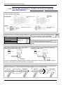
2.4.2 Service parts information 2 : Inverter compressor
Check point 1 : Check connection
Check terminal connection of compressor
(Loose or incorrect wiring)
(RED)
Only for 3-phase type :
Check connection of inverter PCB
(Loose or incorrect wiring)
(BLACK)
BLACK
Main PCB
WHITE
(WHITE)
Compressor
Check point 2 : check winding resistance
Check winding resistance on each terminal
If the resistance value is 0Ω or infinite, replace compressor.
Resistance value :
0.24 Ω (at 20°C) for single phase type
0.79 Ω (at 20°C) for 3-phase type
Check point 3 : replace Main PCB
If check point 1 and 2 do not improve the symptom, replace Main PCB.
Maintenance Document 1544-1
37
Split system (Single phase and 3-phase type)
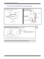
2.4.3 Service parts information 3 : Outdoor unit electronic expansion
valve (EEV, EEV(INJ))
Check point 1 : Check connection
Check connection of connector
(Loose connector or open cable)
EXPANSION VALVE
COIL
Single phase :
EXPANSION
VALVE COIL
(INJ)
3-phase :
EXPANSION VALVE
COIL (INJ)
EXPANSION VALVE COIL
Check point 2 : Check coil of EEV
Remove connector, check each winding resistance of
coil.
Read wire
Resistance value
White-Red
Yellow-Red
46Ω +/- 4Ω
at 20°C
Orange-Red
Blue-Red
If resistance value is abnormal, replace EEV.
Check point 3 : Check voltage from main PCB
Remove connector and check voltage (DC12V)
If it does not appear, replace Main PCB.
Check point 4 : Check noise at start up
Turn on power and check operation noise.
If an abnormal noise does not show, replace Main
PCB.
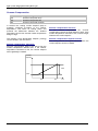
Check point 5 : Check opening and closing operation of valve
When valve is closed, it has a temp. (Add period)
If it is open, it has no temp. (Add period) difference
difference between inlet and outlet.
between inlet and outlet.
CLOSE
Example : Hot gas
OPEN
Example : Hot gas
Pipe (In)
HI TEMP.
Pipe (In)
HI TEMP.
Pipe (Out)
HI TEMP.
Pipe (Out)
Normal TEMP.
There is no refrigerant flow coming to EEV(INJ) while the liquid injection is inactive. Check whether the liquid
injection is active before executing check point 5 for EEV(INJ).
Check point 6 : Check stainer
Stainer normally does not have temperature difference between inlet and outlet as shown in 1, but if there is a
difference as shown in 2, there is a possibility of inside clogged. In this case, replace stainer.
Pipe (In)
38
Pipe (Out)
Pipe (In)
Pipe (Out)
Maintenance Document 1544-1
Split system (Single phase and 3-phase type)
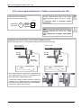
2.4.4 Service parts information 4 : Outdoor unit solenoid valve (SV)
Check point 1 : Check connections
Check connection of connector
(Loose connector or open cable)
BLUE
2
2
CN501
BLUE
1
1
SV
SOLENOID
COIL (INJ)
Check point 2 : Check solenoid coil
Remove connector and check if coil is open
(normal resistance value of each coil : 1495+/7%)
If resistance value is abnormal, replace
solenoid coil.
Check point 3 : Check voltage from main
PCB
Remove connector and check the voltage
(AC230V).
If the voltage does not appear, replace Main
PCB.
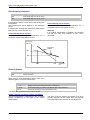
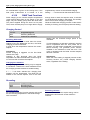
Check point 4 : check opening and closing operation valve
Depending on the injection activity, check if valve is operating normally.
(When valve opens, ther is no temperature difference between inlet and outlet)
Injection is inactive
Pipe (In) TEMP. HI.
Pipe (Out) TEMP. Normal
Injection is active
Pipe (In) TEMP.= Pipe (Out) TEMP.
Pipe (In)
HI TEMP.
Pipe (In)
HI TEMP.
CLOSE
Pipe (Out)
Normal TEMP.
SOLENOIDE COIL
OPEN
Pipe (Out)
HI TEMP.
SOLENOIDE COIL
If the valve closes by removing the connector of the
valve which does not close, it is considered to be
Main PCB failure. Replace Main PCB.
If it does not closeby removing connector, there is a
possibility of (1) clogging by dirt, or (2) deformation
by the heat at the time of solenoid valve installation.
In this case, replace solenoid valve.
Maintenance Document 1544-1
39
Split system (Single phase and 3-phase type)
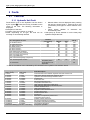
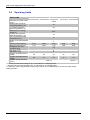
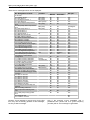
2.5
Operating Limits
HEAT PUMP
Single phase
112
140
3-phase
140
160
Min/max OT in heat mode
-25/35
(°C)***
Heating floor maximum
45
water temperature (°C)
LT radiator maximum
60
water temperature (°C)
Min/max OT in cooling
8/43
mode(°C)
Cooling floor minimum
18
water temperature (°C)
Fan coil minimum water
8
temperature (°C)
Water circuit max pressure
3
(Bar)
Maximum flow rate (l/h)
2340
2920
2340
2920
3290
Minimum flow rate (l/h)
1170
1460
1170
1460
1650
Refrigerant circ max
4,2
pressure (kPa)
Min delta T (°C)
4
Max delta T (°C)
8
Outdoor unit Noise level 1
55
56
53
55
56
(dBA)*
Outdoor unit Noise level 5
39
41
39
41
42
(dBA)**
Outdoor unit air flow rate
3100 x 2
3450 x 2
(m3/h)
* Acoustic pressure level reading at 1m, in open field, on a reflecting plane.
** Acoustic pressure level reading at 5m, in open field, on a reflecting plane.
*** When the outdoor temperature continuously exceeds 35°C, DHW heating is done by the water heater
heating element.
40
112
Maintenance Document 1544-1
Split system (Single phase and 3-phase type)
3
Failures
3.1
Hydraulic, Electric and Refrigeration Systems
3.1.1 Hydraulic System
If the installation is fitted with a heating floor, the most
common failures are those listed below:
FAILURE CASES
CONSEQUENCES
SOLUTIONS
APPLIED
BY
1- Clogged filter*
or sludge in system
Flow pressure too high
clean filter or desludge
Installer
∆T too high (>7)
clean filter or desludge
change pump with warranty if pump
is faulty
change pump with warranty if pump
is faulty
change pump with warranty if pump
is faulty
Installer
Service
station
Service
station
Service
station
Installer
Zero flow pressure
2- Pump out of order
current too high (rotor locked)
zero current (winding cut off)
pump stuck
3-Leak
Low level in expansion vessel
release with a screwdriver
On collector,
isolate heating
circuits to
determine which
heating circuit is
perforated.
On collector,
check heating
circuit flow/return
temps (infrared
thermometer)
If no clogged
heating circuit,
check for
crushing with
infrared camera
4- Clogged heating
circuit (crushed pipe)
Very high difference between floor
flow/return temp
5- Misbalance
Very high difference between floor
flow/return temp
Rebalance
Very high difference between floor
flow/return temp
On collector,
check heating
circuit flow/return
temps (infrared
thermometer)
6- Floor undersized or
charge losses too high
Pipe leak. Pipe
under warranty if
faulty
Leak in heating
circuit. Floor
again.
Service
station
Installer
Clear with test
pump
Call the installer's
or floor coverer's
responsibility into
question
Service
station
Installer
Installer
Call the installer's
or
responsibility into
Service
question
station
* Not required and not shown on the device.
Maintenance Document 1544-1
41
Split system (Single phase and 3-phase type)
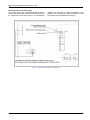
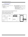
3.1.2 Electrical System
Outdoor Unit Overvoltage
Check for possible causes in the list below (this list is
not exhaustive):
Problem with the compressor
Main board
Faulty power relay
Steps to be followed before performing any work
on the Inverter module:
First switch off the system using the circuit
breaker at the head of the line.
Remove the unit cover and then remove the
Inverter module cover.
Measure the voltage at the condenser terminals.
You should find a value of 5 Vdc or less.
Inspection of the Power Transistor Module (Main board)
Disconnect the compressor relay and the condenser
connection. Measure the resistance value at the
points shown on the illustration, and then compare
the values observed with those in the table.
3-phase type
Multimeter
Resistor
Terminal block
Single phase type
N
W
1 MOhm
or more
V
U
Main PCB
P
42
Maintenance Document 1544-1
Split system (Single phase and 3-phase type)
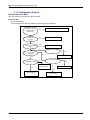
3.1.3 Refrigeration System
Unit produces no heat
The unit remains in continuous scanning mode.
Initial checks:
Check the settings
Are the data sent by the user interface received by the heat pump?
Hydraulic unit
electronic circuit
sending data to
outdoor unit ?
No
Hydraulic unit electronic system faulty
Yes
Compressor
running ?
No
Inspect PCB
Yes
Operating pressure
OK ?
Yes
No
Charge to balance
No
Problem solved?
Yes
4-way valve
switching ?
No
Servicing complete
Yes
Expansion correct ?
Yes
Valve coil faulty ?
No
Yes
Change
expansion valve
Change coil
No
Inspect refrigeration
lines (clogging)
Maintenance Document 1544-1
Change 4-way valve
after testing
43
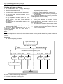
Split system (Single phase and 3-phase type)
Outdoor unit does not defrost
Is condensation drain properly discharged
(outdoor unit directly on the ground)?
Are the auxiliaries powered?
In boiler backup mode, is the boiler authorized?
In very cold areas, a fusing resistance value is
recommended.
Is the installation regularly subject to microoutages of power (frequent outages on the mains
power system may also cause defrosting
problems)?
Is there a peak day clearing (EJP) outage on the
installation?
Does the heat pump regularly switch to high
pressure safety mode?
If this occurs at low temperatures (< 5 °C), we
recommend checking that the water pump is
operating properly.
Is
the
charge
correct
(refer
to
the
temperature/pressure curve)?
Insufficient charging will result in frequent icing.
Overcharging will result in frequently switching to
HP safety mode.
(If you still have doubts as to the charge, perform the
charging with an electronic scale).
Outdoor unit defrosting is controlled by the
exchanger sensor and the controller board.
If the defrost sensor is not iced up while the rest of
the exchanger is, then:
Move the sensor between the exchanger blades
to a place where the exchanger is iced up.
If all these points have been checked, replace the
outdoor controller board.
Note:
Outdoor unit defrosting is controlled by the exchanger sensor and the controller board. If no frosting is observed
and no anomaly is otherwise noted, the sensor and board must be inspected and the faulty part will have to be
replaced.
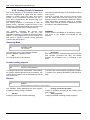
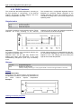
Defrosting
a. Defrost beginning conditions
Start of heat mode
(Compressor ON)
(No defrost for 10 min)
1st defrost
Subsequent defrosts
Cumulative compressor operating time
17’ < t < 62’
O Exch T
≤ -9°C
62’ < t < 240’
O Exch T
≤ -5°C
240’ < t
O Exch T
≤ -3°C
35’ < t < 240’
O Exch T
≤ -10°C
240’ < t
O Exch T
≤ -3°C
OT – O Exch T >5°C
Defrost
O Exch T : outdoor unit exchanger temperature
OT : outdoor temperature
t : Cumulative compressor operating time
44
Maintenance Document 1544-1
Split system (Single phase and 3-phase type)
b. Defrost ending conditions
With all models, defrosting stops if the exchanger
temperature is above 10 °C or if the defrosting time is
over 15 minutes).
Crankcase heater
When the outdoor exchanger temperature is below
-18°C and the heating mode has been stopped for
30 minutes, the compressor windings are powered
and maintain the compressor temperature.
3.2
Compressor Operating Checks
Using a multimeter set to mega ohm, check that the
resistance value across the windings is identical
irrespective of the phase (between U and V, V and
W, W and U). This value should be approx. 1 Ohm.
3.3
Check that resistance between each phase and the
earth is infinite. The result should be clear (you
should not see the displayed value increasing slowly
up to a value greater than the multimeter maximum
rating).
Refrigeration Circuit Leak Test
The new regulation requires annual leak testing of
installations with a refrigerant charge higher than 2kg.
3.4
When operation has started and the temperature
becomes higher than -16°C, heating stops.
Leak testing is to be performed with an approved
detector that has been appropriately calibrated.
Troubleshooting
The heat pump is not operating at all (no illuminated indicator):
Are the power supply voltage and frequency
normal?
Is the connection to mains correct?
Have all the connectors been properly inserted?
Are the fuses on the outdoor unit still operating?
If not, change the bad fuse(s).
Is the connection between the outdoor unit and
the Hydraulic Unit correct? Do you read 230V AC
between terminals 1 and 2 of the Hydraulic Unit
terminal block?
Maintenance Document 1544-1
Do you read 230V AC at the transformer primary
on the Hydraulic Unit? If not, change the board.
Is there any voltage on the transformer
secondary on the Hydraulic Unit? If not, check
the thermal fuse. If the fuse is good, the error
comes from the board.
45
Split system (Single phase and 3-phase type)
4 Control Settings
4.1
General
The settings described below are those which can be
modified by the user.
We wish to remind you that changing the settings
below may cause the heat pump to behave in an
undesirable way. A testing period should be
conducted before the permanent settings of the heat
pump are confirmed. This may require a number of
changes to be made by the installer.
There are 4 access levels:
U: end-user level
I: commissioning level (installer start-up)
S: engineer level (specialist)
C: OEM level (manufacturer) (not available)
46
Maintenance Document 1544-1
Split system (Single phase and 3-phase type)
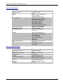
4.2
Function Table
COMMAND
LINE
ACCESS
LEVEL
1
2
3
5
6
U
U
U
S
S
20
U
FUNCTION
Time of day and date
Hour/minutes
Day/month
Year
Start of summertime
End of summertime
Operator section
Language
22
S
Info
26
27
28
S
S
S
29
S
70
S
Operation lock
Programming lock
Direct adjustment...
Temperature unit
Pressure unit
Software version
Time prog heating circuit 1
500
U
Preselection
st
00:00…23:59
01.01…31.12
1900…2099
01.01…31.12
01.01…31.12
Mon-Sun ¦ Mon-Fri ¦ Sat - Sun ¦
Mon ¦ Tue ¦ Wed ¦Thu ¦ Fri ¦ Sat
¦Sun
U
U
U
U
U
U
U
U
1 phase on
00:00…--:-1st phase off
00:00…--:-2nd phase on
00:00…--:-2nd phase off
00:00…--:-3rd phase on
00:00…--:-3rd phase off
00:00…--:-Copy
Default values, Circuit 1
No/yes
Time prog heating circuit 2
520
U
Preselection
521
522
523
524
525
526
535
536
U
U
U
U
U
U
U
U
1 phase on
1st phase off
2nd phase on
2nd phase off
3rd phase on
3rd phase off
Copy
Default values, Circuit 2
Time program 4 / DHW
560
U
Preselection
st
No
No/yes
No
Mon-Sun ¦ Mon-Fri ¦ Sat - Sun ¦
Mon ¦ Tue ¦ Wed ¦Thu ¦ Fri ¦ Sat
¦Sun
Mon-Sun
U
Preselection
Maintenance Document 1544-1
6:00
22:00
--:---:---:---:--
6:00
22:00
--:---:---:---:--
600
1 phase on
1st phase off
Mon-Sun
00:00…--:-00:00…--:-00:00…--:-00:00…--:-00:00…--:-00:00…--:--
1 phase on
00:00…--:-1st phase off
00:00…--:-2nd phase on
00:00…--:-2nd phase off
00:00…--:-3rd phase on
00:00…--:-3rd phase off
00:00…--:-Copy
Default values
No/yes
Time program 5 / Cooling circuit
U
U
Off
Off
Confirm
°C
bar
Mon-Sun
U
U
U
U
U
U
U
U
601
602
Temporarily
Mon-Sun ¦ Mon-Fri ¦ Sat - Sun ¦
Mon ¦ Tue ¦ Wed ¦Thu ¦ Fri ¦ Sat
¦Sun
561
562
563
564
565
566
575
576
st
25.03
25.10
English
Temporarily /
Permanent
Off/on
Off/on
Auto/confirm
°C, °F
bar, psi
501
502
503
504
505
506
515
516
st
FACTORY
SETTING
SETTING RANGE
00:00
05:00
14:30
17:00
--:---:-No
Mon-Sun ¦ Mon-Fri ¦ Sat - Sun ¦
Mon ¦ Tue ¦ Wed ¦Thu ¦ Fri ¦ Sat
¦Sun
Mon-Sun
00:00…--:-00:00…--:--
8:00
20:00
47
Split system (Single phase and 3-phase type)
COMMAND
LINE
48
ACCESS
LEVEL
FUNCTION
2nd phase on
2nd phase off
3rd phase on
3rd phase off
Copy
Default values
Holidays heating circuit 1
Preselection
Period start (Day / Month)
Period end (Day / Month)
Operating level
Holidays heating circuit 2
Preselection
Period start (Day / Month)
Period end (Day / Month)
Operating level
Heating circuit 1
603
604
605
606
615
616
U
U
U
U
U
U
641
642
643
648
U
U
U
U
651
652
653
658
U
U
U
U
710
U
Comfort setpoint
712
U
Reduced setpoint
FACTORY
SETTING
SETTING RANGE
00:00…--:-00:00…--:-00:00…--:-00:00…--:--
--:---:---:---:--
No/yes
No
Period 1…8
01.01…31.12
01.01…31.12
Period 1
Frost protection ¦ Reduced
Frost protection
Period 1…8
01.01…31.12
01.01…31.12
Period 1
Frost protection ¦ Reduced
Frost protection
Reduced temp to
35°C
20°C
19°C
4°C to Reduced
temp
20°C…35°C
0,1…4
-4,5°C…4,5°C
Off, on
8°C…30°C
-10°C…10°C
28°C
0,5
0°C
Off
18°C
-2°C
8°C… 95°C
8°C
8°C… 95°C
1%...100%
55°C
50%
Off ¦ Down to reduced
setpoint ¦ Down to frost
prot setpoint
Down to reduced
setpoint
714
U
Frost protection setpoint
716
720
721
726
730
732
S
I
I
I
I
S
740
I
741
750
I
S
Comfort setpoint maximum
Heating curve slope
Heating curve displacement
Heating curve adaption
Summer/winter heating limit
24-hour heating limit
Flow temp setpoint min (for fan
convectors)
Flow temp setpoint max
Room influence
780
S
Quick setback
790
791
800
801
830
834
850
851
856
857
900
S
S
S
S
S
S
I
I
I
I
S
901
902
U
U
Optimum start control max
Optimum stop control max
Reduced setpoint increase start
Reduced setpoint increase end
Mixer valve boost
Actuator running time
Floor curing function
Floor curing setpoint manually
Floor curing day current
Floor curing day completed
Optg mode changeover
Cooling circuit 1
Operating mode
Comfort setpoint
907
U
Release
24h/day ¦ Time
program HC ¦ Time
program 5
24h/day
908
909
912
913
918
919
I
I
I
S
S
S
Flow temp setp at OT 25°C
Flow temp setp at OT 35°C
Cooling limit at OT
Lock time at end of heating
Summer comp start at OT
Summer comp end at OT
6…35°C
6…35°C
---/8…35°C
---/8…100h
20…50°C
20…50°C
20°C
16°C
20°C
24h
26°C
35°C
0…360min
0…360min
-30°C…10°C
-30°C…10°C
0…50°C
30…873s
0…5
0°C…95°C
0…32
0…32
8°C
180 min
60 min
---5°C
0
240s
Off
25°C
Protection mode
Automatic
24°C
Off ¦ Automatic
15…40°C
Maintenance Document 1544-1
Split system (Single phase and 3-phase type)
COMMAND
LINE
ACCESS
LEVEL
FUNCTION
920
923
924
928
932
938
941
945
963
S
S
S
S
S
S
S
S
S
Summer comp setp increase
Flow temp setp min OT 25°C
Flow temp setp min OT 35°C
Room influence
Room temp limitation
Mixing valve decrease
Actuator running time
Mixing valve in heating mode
With prim contr/system pump
Heating circuit 2
1010
U
Comfort setpoint
1012
U
Reduced setpoint
1014
U
Frost protection setpoint
1016
1020
1021
1026
1030
1032
S
I
I
S
I
S
1040
S
1041
1050
I
I
Comfort setpoint maximum
Heating curve slope
Heating curve displacement
Heating curve adaption
Summer/winter heating limit
24-hour heating limit
Flow temp setpoint min (for fan
convectors)
Flow temp setpoint max
Room influence
1080
S
Quick setback
1090
1091
1100
1101
1130
1134
1150
1151
1156
1157
1200
S
S
S
S
S
S
I
I
I
I
S
1610
1612
U
U
Optimum start control max
Optimum stop control max
Reduced setpoint increase start
Reduced setpoint increase end
Mixer valve boost
Actuator running time
Floor curing function
Floor curing setpoint manually
Floor curing day current
Floor curing day completed
Optg mode changeover
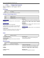
Domestic hot water
Nominal setpoint
Reduced setpoint
1620
I
Release of DHW load
1640
I
Legionella function
1641
1642
I
I
2056
U
2803
2843
2844
2862
S
S
S
S
Legionella function periodically
Legionella function weekday
Swimming pool
Setpoint source heating
Heat pump
Overrun time cond pump
Compressor off time min
Switch-off temp max
Locking time stage 2
Maintenance Document 1544-1
FACTORY
SETTING
SETTING RANGE
---/1…10°C
6…35°C
6…35°C
---/1…100%
---/0…4°C
0…20°C
30…650s
Control ¦ Open
No ¦ Yes
Reduced temp to
35°C
4°C
18°C
18°C
80%
0.5°C
0°C
120s
Open
No
20°C
19°C
4°C to Reduced
temp
20…35°C
0,1…4
8°C
Off, on
8°C…30°C
-10°C…10°C
28°C
0,5
0°C
Off
18°C
-2°C
8°C… 95°C
8°C
8°C… 95°C
1%...100%
55°C
50%
Off ¦ Down to reduced
setpoint ¦ Down to frost
prot setpoint
Down to reduced
setpoint
-4,5°C…4,5°C
0…360min
0…360min
-30…10°C
-30…10°C
0…50°C
30…873s
0°C…95°C
0…32
0…32
180 min
60 min
---5°C
0°C
240s
Off
25°C
0
Protection mode
Thc…65°C
8°C….Thc
24h/day
Heating circ time pgms
Time program 4/DHW
Off-peak rate
4: Time pgm 4/DHW or
Off-peak rate
Off
Periodically
Fixed weekday
55°C
40°C
Time program
4/DHW
Off
1 to 7
Mon,…Sun
7
Sunday
8…80
22
0…240s
0…120min
8°C… 100°C
0…40min
240
8min
75°C
5min
49
Split system (Single phase and 3-phase type)
COMMAND
LINE
ACCESS
LEVEL
FUNCTION
FACTORY
SETTING
SETTING RANGE
2873
2882
2884
2886
2916
2920
S
S
S
S
S
S
3700
3701
3705
3720
3723
S
S
S
S
S
5024
5030
5055
5057
S
S
S
S
Compressor mod run time
Release integr electric flow
Release el flow at OT
Compensation heat deficit
Max setpoint HP DHW charg
With electrical utility lock
Supplementary source
Release below outside temp
Release above outside temp
Overrun time
Switching integral
Locking time
DHW storage tank
Switching differential
Charging time limitation
Recooling temp
Recooling collector
5061
S
Electric immersion heater release
5093
S
Not used
5700
5710
I
I
Pre-setting
Heating circuit 1
5711
I
Cooling circuit 1
5715
I
Heating circuit 2
5731
I
DHW ctrl elem Q3
5806
I
Type el imm heater flow
5981
5983
5985
6098
6100
6120
6205
6220
S
S
S
S
S
S
S
S
Cont type input EX1
Cont type input EX2
Cont type input EX3
Not used
Readjustm outside sensor
Frost protection plant
Reset to default parameters
Software version
Function input H33
6420
I
6421
I
Optg mode change HCs+DHW ¦ Optg mode changeover DHW ¦ Optg mode changeover HCs ¦
Optg mode changeover HC1 ¦ Optg mode changeover HC2 ¦ Optg mode changeover HC3 ¦
Error/alarm message ¦ Release swi pool source heat ¦ Release swi pool solar ¦ Dewpoint
monitor
NC ¦ NO
Contact type H33
NO
6600
I
Not used
10…240s
0… 500°Cmin
-30°C…30°C
Off ¦ On ¦ Only with
floor curing fct
8°C… 80°C
Lock/release
240
100°Cmin
2°C
Off
60°C
Released
-50…50°C
-50…50°C
0...120min
0… 500°Cmin
0...120min
2°C
0…20°C
10…600min
8…95°C
7°C
90 min
65°C
Summer
Off ¦ Summer ¦ Always
24h/day
DHW release
Time program 4/DHW
20min
100°Cmin
30min
DHW release
Configuration
1 to 12
1
On
Off ¦ On
Off
4-pipe system
2-pipe system
Off
Off ¦ On
No charging request ¦
Charging pump ¦
Diverting valve
1 : 3-stage, 2 : 2-stage
excluding, 3 : 2-stage
complementary, 4 :
Modulating UX
NC ¦ NO
NC ¦ NO
NC ¦ NO
-20…20°C
-3…3°C
On/off
No/yes
0…99
On
Diverting valve
3 : 2-stage
complementary
NO
NC
NO
0°C
0°C
On
No
--
LPB system
0…16
1
No/yes
Date/time/code
Date/time/code
Date/time/code
Date/time/code
Date/time/code
Date/time/code
Date/time/code
No
Errors
6711
6800
6802
6804
6806
6808
6810
6812
50
U
S
S
S
S
S
S
S
Reset HP
History 1
History 2
History 3
History 4
History 5
History 6
History 7
Maintenance Document 1544-1
Split system (Single phase and 3-phase type)
COMMAND
LINE
ACCESS
LEVEL
FUNCTION
6814
6816
6818
S
S
S
History 8
History 9
History 10
7070
7071
7073
7141
7142
7150
S
S
S
U
S
I
Service / special operation
HP interval
1..240 months
HP time since maint
0..240 months
Cur starts compressor 1/hrs run
0…12
Emergency operation
On/off
Emergency operating function type
Manual/auto
Simulation outside temp
-50…50°C
Input / output test
7700
I
Relay test
7710
7712
7716
7719
7722
7723
7724
7725
7820
7821
7822
7823
7824
7825
7830
7832
7849
7911
7912
7913
7973
7974
7975
7976
7977
7978
7996
I
I
I
I
I
I
I
I
I
I
I
I
I
I
I
I
I
I
I
I
I
I
I
I
I
I
I
8000
8001
8003
8004
I
I
I
I
Output test UX1
PWM-Signal UX1
Output test UX2
PWM-Signal UX2
Cooling mode DO2
Heat pump D3
Output test UX3
Voltage value UX3
Sensor temp BX1
Sensor temp BX2
Sensor temp BX3
Sensor temp BX4
Sensor temp BX5
Sensor temp BX6
Sensor temp BX21 module 1
Sensor temp BX21 module 2
Contact status H2, module 2
Input EX1
Input EX2
Input EX3
Sensor temp BX31
Sensor temp BX32
Sensor temp BX33
Sensor temp BX34
Sensor temp BX35
Sensor temp BX36
Contact state H33
State of plant
State heating circuit 1
State heating circuit 2
State DHW
State cooling circuit 1
Maintenance Document 1544-1
FACTORY
SETTING
SETTING RANGE
Date/time/code
Date/time/code
Date/time/code
--0
0
Off
Manual
---
No test
All OFF
Relay output QX1
Relay output QX2
Relay output QX3
Relay output QX4
Relay output QX5
Relay output QX6
Relay output QX31
Relay output QX32
Relay output QX33
Relay output QX34
Relay output QX35
Relay output QX36
Relay output QX21 module 1
Relay output QX22 module 1
Relay output QX23 module 1
Relay output QX21 module 2
Relay output QX22 module 2
Relay output QX23 module 2
0…100%
0…100%
0…100%
0…100%
On/off
On/off
0…100%
0…100%
-28…350°C
-28…350°C
-28…350°C
-28…350°C
-28…350°C
-28…350°C
-28…350°C
-28…350°C
Open, Closed
0V ¦ 230V
0V ¦ 230V
0V ¦ 230V
-28…350°C
-28…350°C
-28…350°C
-28…350°C
-28…350°C
-28…350°C
Open ¦ Closed
No test
---%
0
-0
Off
Off
---------Open
---------Open
-----
51
Split system (Single phase and 3-phase type)
COMMAND
LINE
52
ACCESS
LEVEL
8006
8007
8010
8011
8022
I
I
I
I
I
8402
8403
8406
8410
8412
8413
8414
8425
8454
8455
8456
8457
I
I
I
U
U
U
I
I
S
S
S
S
8700
8701
8702
8703
8704
8730
8731
8732
8740
8743
8756
8760
8770
8773
8820
8821
U
U
U
I
I
I
I
I
U
U
U
I
U
U
I
I
8830
U
8840
8841
8842
8843
8900
8950
8957
9031
9032
9033
9034
9035
9050
9051
9052
9053
9054
9055
9071
9072
S
S
S
S
U
S
S
I
I
I
I
I
I
I
I
I
I
I
U
U
FUNCTION
State heat pump
Not used
Not used
State swimming pool
State supplementary source
Diagnostics heat source
El imm heater flow 1
El imm heater flow 2
Condenser pump
Return temp HP
Flow temp HP
Compressor modulation
Modulation electric flow
Temp diff condenser
Locking time HP
Counter number of locks HP
Hours run el flow
Start counter el flow
Diagnostics consumers
Outside temperature
Outside temp min
Outside temp max
Outside temp attenuated
Outside temp composite
Heating circuit pump, circuit 1
Mixer valve HC1 open
Mixer valve HC1 closed
Room temp 1
Flow temp 1
Flow temperature cooling 1
Heating circulation pump, circuit 2
Room temp 2
Flow temp 2
DHW pump
Electric immersion heater DHW
DHW (domestic hot water)
temperature
Hours run DHW pump
Start counter DHW pump
Hours run el DHW
Start counter el DHW
Swimming pool temp
Common flow temp
Common flow setp refrig
Relay output QX1
Relay output QX2
Relay output QX3
Relay output QX4
Relay output QX5
Relay output QX21 module 1
Relay output QX22 module 1
Relay output QX23 module 1
Relay output QX21 module 2
Relay output QX22 module 2
Relay output QX23 module 2
Relay output QX31
Relay output QX32
FACTORY
SETTING
SETTING RANGE
-----Off/on
Off/on
Off/on
0…140°C
0…140°C
0…100%
0…100%
-50…140°C
0…2730h
0…65535
0…2730h
0…65535
Off
Off
Off
----------
-50…50°C
-50…50°C
-50…50°C
-50…50°C
-50…50°C
Off/on
Off/on
Off/on
0…50°C
0…140°C
0…140°C
Off/on
0…50°C
0…140°C
Off/on
Off/on
-----Off
Off
Off
---Off
20°C
-Off
Off
0…140°C
55°C
0…2730h
0…2730h
0…2730h
0…65535
0…140°C
0…140°C
0…140°C
Off/on
Off/on
Off/on
Off/on
Off/on
Off/on
Off/on
Off/on
Off/on
Off/on
Off/on
Off/on
Off/on
----22°C
--On
On
On
Off
Off
Off
Off
Off
Off
Off
Off
On
On
Maintenance Document 1544-1
Split system (Single phase and 3-phase type)
COMMAND
LINE
9073
9074
9075
4.3
ACCESS
LEVEL
U
U
U
FUNCTION
FACTORY
SETTING
SETTING RANGE
Relay output QX33
Relay output QX34
Relay output QX35
Off/on
Off/on
Off/on
Off
Off
Off
Adjustment Function Details
4.3.1 Date and Time Functions
The controller has an annual clock which contains the time, the day of the week and the date.
In order for the function to operate, the time and date must be set properly on the clock.
LINE NO.
1
2
3
5
6
PROGRAMMING LINE
Hour/minutes
Day/month
Year
Start of summertime
End of summertime
NOTE: Summer time/winter time change
Dates have been set for changing to summer time or to winter time. The time changes automatically from 2am
(winter time) to 3am (summer time) or from 3am (summer time) to 2am (winter time) on the first Sunday
following the respective date.
4.3.2 User Interface Functions
LINE NO.
20
22
26
27
28
29
PROGRAMMING LINE
Language
Info
Operation lock
Programming lock
Direct adjustment...
Temperature unit
Pressure unit
Info (22):
Temporary:
After pressing the Info key, the information display
returns to the basic "predefined" display after 8
minutes or when pressing the operating mode key.
Permanent:
After pressing the Info key, the information display
returns to the "new" standard display after a
maximum of 8 minutes. The last selected information
value is shown in the new basic display.
Maintenance Document 1544-1
Operation lock (26):
If the operating lock is activated, the following control
elements can no longer be adjusted:
Heating circuit mode, DHW mode, room temp comfort
setpoint (knob), occupancy key.
53
Split system (Single phase and 3-phase type)
Programming lock (27):
If the programming lock is activated, the setting
values are displayed but may no longer be changed.
Permanent Suspension of Programming
First perform a temporary suspension, then cancel
"Programming lock" on line 27.
Temporary Suspension of Programming
The programming lock can be temporarily
deactivated at programming level. To do this,
simultaneously press the OK and ESC keys for at
least 3 seconds. The temporary suspension of the
programming lock remains in effect until you exit the
programming.
Direct adjustment... (28):
Automatic storage
Correction of the setpoint with the knob is adopted
without a particular confirmation (timeout) or by
pressing the OK key.
Storage with confirmation
Correction of the setpoint with the knob will be
adopted only after pressing the OK key.
Heating Circuit Assignment
LINE NO.
70
PROGRAMMING LINE
Software version
Software version
The indication shows the current version of the user
interface.
4.3.3 Time Program Functions (heating circuit 1 & 2, DHW, cooling)
Several control programs are available for the heating
circuits and the production of DHW. They are initiated
in "Automatic" mode and control the change in
temperature levels (and therefore the associated
setpoints, reduced and comfort) via the adjusted
changeover times.
Enter changeover times:
Changeover times can be adjusted in a combined
way, i.e., identical times for several days or distinct
times for certain days. Preselecting groups of days
(e.g., Mon...Fri and Sat...Sun) having the same
changeover times makes adjustment of the
changeover program considerably shorter.
Changeover Points
Line no.
HC1 HC2
500
520
4/DHW
560
5
600
Programming line
501
502
503
504
505
506
561
562
563
564
565
566
601
602
603
604
605
606
Preselection
(Mon-Sun / Mon-Fri / Sat – Sun / Mon...Sun)
521
522
523
524
525
526
1st phase On
1st phase Off
2nd phase On
2nd phase Off
3rd phase On
3rd phase Off
Standard Program
Line no.
516, 536, 576, 616
Programming line
Default values
(No /Yes)
All time programs can be reset to factory settings.
Each time program has its own command line for this
reset action.
54
In this case, individual settings will be lost!
Maintenance Document 1544-1
Split system (Single phase and 3-phase type)
Holidays:
Line no.
HC1
642
643
648
Programming line
HC2
652
653
658
Period start (Day / Month)
Period end (Day / Month)
Operating level
The holiday program enables changing the heating
circuits over to a selected operating level according to
the date (calendar).
Important !
The holiday program can be used only in the
automatic mode.
4.3.4 Heating Circuit 1 & 2 Functions
Operating Mode
For heating circuits there are several functions
available which can be individually adjusted for each
heating circuit.
The programming lines for the 2nd heating circuit are
displayed only if an extension module has been
connected to the controller.
Operation of heating circuits 1 and 2 is directly
controlled via the operating mode key.
Setpoint Values
Line no.
HC1
710
712
714
716
Programming line
HC2
1010
1012
1014
1016
Comfort setpoint
Reduced setpoint
Frost protection setpoint
Comfort setpoint maximum
Room Temperature:
Room temperature can be set according to different
setpoint values. Depending on the selected mode,
these setpoints are activated and provide different
temperature levels in the rooms.
The ranges of configurable setpoints are defined by
their interdependencies, as shown in the graph
below.
Comfort setpoint
Reduced setpoint
Frost prot. setpoint
Frost protection:
The protection mode automatically prevents an
excessively sharp drop in room temperature.
Maintenance Document 1544-1
In this case the control adopts the frost protection
room setpoint.
55
Split system (Single phase and 3-phase type)
Heating Curve
Line no.
HC1
720
721
726
Programming line
HC2
1020
1021
1026
Heating curve slope
Heating curve displacement
Heating curve adaption
Heating curve slope:
Based on the heating characteristic, the controller
computes the flow temperature setpoint which will be
used for controlling the flow temperature in
consideration of atmospheric conditions. Different
settings can be used to adapt the heating
characteristic so that the heating capacity, and
therefore the room temperature, will match the
individual needs.
o
Increase the setting:
The flow temperature is increased mainly when the
outdoor temperatures are low.
o
Decrease the setting:
The flow temperature is lowered mainly when the
outdoor temperatures are low.
Warning:
The heating curve is adjusted in relation to a room
temperature setpoint of 20°C. If the room temperature
setpoint is modified, the flow temperature setpoint is
automatically recomputed. This will not modify the
setting and amounts to automatically adapting the
curve.
The colder the outdoor temperature, the greater the
extent to which the slope will modify the flow
temperature. In other words, the slope should be
corrected if the room temperature shows a difference
when the outdoor temperature is low, but not when it
is high.
Heating Curves
70
2
Heating Flow Temperature (°C)
60
1,75
1,5
1,25
50
1
0,75
40
0,5
30
20
20,0
0,25
15,0
10,0
5,0
0,0
-5,0
-10,0
-15,0
-20,0
Outdoor Temperature (°C)
56
Maintenance Document 1544-1
Split system (Single phase and 3-phase type)
Information:
To ensure operation, the following requirements
must be met:
A room sensor must be connected.
The "room influence" parameter must be
set between 1 and 99.
The reference room (where the room
sensor is installed) must not contain adjusted
thermostatic valves. If present in the room, these
valves must be fully open.
Operation of this function requires an
adaptation period which can take more or less time
(approx. 1 week) depending on weather conditions
and on the stability of the room temperature
setpoint.
Heating curve displacement
The curve shift (offset) modifies the flow
temperature in a general and even manner over the
full range of outdoor temperature. In other words,
the shift should be corrected when the room
temperature is generally too high or too low.
Heating curve adaption
Adaptation enables the controller to automatically
adapt the heating curve to the present conditions.
This correction may only be activated or
deactivated.
In the latter case, there is no need to correct the
slope and shift.
Eco Functions
Line no.
HC1
730
732
Programming line
HC2
1030
1032
Summer/winter heating limit
24-hour heating limit
Summer/winter heating limit
The summer/winter heating limit switches the heating
on or off through the year according to the
temperature ratio. Changeover is performed
automatically when in automatic mode and thus
avoids the user having to turn the heating on or off.
Changing the input value makes the respective
annual periods (summer/winter) shorter or longer.
If the value is increased:
Changing to winter operating mode is advanced,
changing to summer mode is delayed
Example:
If the value is decreased:
Changing to winter mode is delayed; changing to
summer mode is advanced.
Information:
This function does not work in "Continuous Comfort
temperature" mode. (Sunlight)
The controller displays "ECO".
The outdoor temperature is attenuated to take the
building's dynamics into account.
Attenuated outdoor T
Sum/win heating limit + 1°C
Sum/win heating limit
Sum/win heating limit - 1°C
Days
24-hour heating limit
The 24-hour heating limit is used to switch the
heating on and of in the course of the day, depending
on the outside temperature.This function is used
mainly during intermediate seasons (spring and fall)
to react rapidly in case of fluctuating temperatures.
Maintenance Document 1544-1
Thus, in the following example the changeover
temperature will be 18°C, computed as follows:
57
Split system (Single phase and 3-phase type)
Comfort heating setpoint (710)
24-Hour heating limit (732)
Changeover temperature (710 – 732)
Heating off
Differential (Fixed)
Changeover temperature Heating on
Changing the input value makes the respective
heating periods shorter or longer.
If the value is increased: changeover to
heating mode is advanced; changeover to ECO is
delayed.
If the value is decreased: changeover to
heating mode is delayed; changeover to ECO is
advanced.
22°C
-3°C
=19°C
-1°C
=18°C
Information:
This function will not work in "Continuous Comfort
temperature" mode.
The display will show "ECO".
The outdoor temperature is attenuated to take the
building's thermal dynamics into account.
Flow temperature setpoint
Line no.
HC1
740
741
Programming line
HC2
1040
1041
Flow temp setpoint min (for fan convectors)
Flow temp setpoint max
This limitation allows to define a range for the orders
to start. When instructed to start the heating circuit
reaches the threshold, this record remains
permanently at the maximum or minimum, even if the
heat demand continues to increase or decrease.
Room Influence
Line no.
HC1
750
Programming line
HC2
1050
Room influence
Control types:
When using a room temperature sensor there are 3
different types of control to choose from.
SETTING
CONTROL TYPE
---%
Simple control according to outdoor conditions *
1...99 %
Control according to outdoor conditions with room influence *
100 %
Control according to room temperature only
* Requires the connection of an outdoor sensor
Simple control according to outdoor conditions
The flow temperature is computed via the heating
curve according to the averaged outdoor
temperature.
This type of control requires proper adjustment of the
heating curve, as the control does not take the room
temperature into account for this adjustment.
Control according to outdoor conditions with
room influence
The difference between the room temperature and
the setpoint value is measured and taken into
account for temperature control. This enables taking
58
into account possible heat inputs and ensures a more
even room temperature.
The influence of the difference is defined as a
percentage. The better the installation in the
reference room (accurate room temperature, correct
installation location, etc.) the higher will be the value
that can be set.
Example:
Approx 60%: the reference room is appropriate
Approx 20 %: the reference room is inappropriate
Information:
Activation of the function requires taking into account
the following requirements:
Maintenance Document 1544-1
Split system (Single phase and 3-phase type)
A room sensor must be connected.
The "room influence" parameter must be set
between 1 and 99.
The reference room (where the room sensor
is installed) must not contain adjusted thermostatic
valves. If present in the room, these valves must be
fully open.
Control according to room temperature only
The flow temperature is adjusted according to the
room temperature setpoint, the current room
temperature and its evolution. A slight increase in
room temperature, for example, causes an immediate
drop in the flow temperature.
Information:
Activation of the function requires taking into account
the following requirements:
A room sensor must be connected.
The "room influence" parameter must be set
to 100%.
The reference room (where the room sensor is
installed) must not contain adjusted thermostatic
valves. If present in the room, these valves must be
fully open.
Quick setback
Line no.
HC1
780
Programming line
HC2
1080
Quick setback
During quick setback, the heating circuit pump is
deactivated and, in the case of mixing circuits, the
mixing valve is fully closed.
When using a room sensor, the function keeps the
heating off until the room temperature drops to the
level of the "Reduced" or "Frost protection" setpoint.
If the room temperature falls to the reduced or frost
level, the heating circuit pump is activated and the
mixing valve released.
Composite outside
temperature
15°C
10°C
5°C
0°C
-5°C
-10°C
-15°C
-20°C
Quick setback switches the heating off for a certain
period of time, depending on the outside temperature
and the building time constant.
Duration of quick setback when "Comfort" setpoint
minus "Reduced" setpoint = 2 K (e.g. "Comfort"
setpoint = 20 °C and "Reduced" setpoint = 18 °C)
Building time constant [h]
5
Duration of quick setback [h]
7.7
3.3
2.1
1.6
1.3
1.0
0.9
0.8
Optimisation at switch-on and switch-off
Line no.
HC1
790
791
Programming line
HC2
1090
1091
Optimum start control max
Optimum stop control max
Optimum start control max
The change in temperature levels is optimised in
such a way as to reach the comfort setpoint during
changeover times.
Maintenance Document 1544-1
Optimum stop control max
The change in temperature levels is optimised in
such a way as to reach the comfort setpoint -1/4 °C
during changeover times.
59
Split system (Single phase and 3-phase type)
Reduced Setpoint Increase
Line no.
HC1
800
801
Programming line
HC2
1100
1101
Reduced setpoint increase start
Reduced setpoint increase end
This function is used mainly in heating installations
that do not have high supplies of power (e.g. low
energy homes). In that case, when outdoor
temperatures are low, adjusting the temperature
would be too long.
Comfort
setpoint(710)
Begin
increase(800)
Increasing the reduced setpoint prevents excessive
cooling of the rooms in order to shorten the
temperature adjustment period when changing over
to the comfort setpoint.
End increase
(801)
Reduced
setpoint(712)
Averaged OT
Mixing Valve Control
Line no.
HC1
830
834
Programming line
HC2
1130
1134
Mixer valve boost
Actuator running time
Mixer valve boost
The controller adds the increase set here to the
current flow setpoint and uses the result as the
temperature setpoint for the heat generator.
Actuator running time
For 3-position control the valve Actuator running time
can be adjusted. With a 2-position servomotor, the
adjusted travel time is inoperative.
Controlled floor drying function
Line no.
HC1
850
851
856
857
Programming line
HC2
1150
1151
1156
1157
Floor curing function
Floor curing setpoint manually
Floor curing day current
Floor curing day completed
This function is used in the controlled drying of floors.
It adjusts the flow temperature to a temperature
profile. Drying is performed by floor heating via the
heating circuit with a mixing valve or with a pump.
Floor curing function
Off:
The function is deactivated.
Heating operational (Fh):
The first part of the temperature profile
automatically completed.
Heating "ready for occupancy" (Bh)
60
is
The second part of the temperature profile is handled
automatically..
Heating "ready for occupancy" / Heating
operational
The full temperature profile (1st and 2nd part) is
performed automatically.
Manual
No temperature profile is performed, but the control is
performed according to the "manual controlled drying
setpoint". The function is automatically terminated
after 25 days
Maintenance Document 1544-1
Split system (Single phase and 3-phase type)
electricity, settings). Otherwise, the floors to be dried
may be damaged!
o
The function may be prematurely interrupted
by setting it to Off.
o
The maximum flow temperature limitation
remains active.
Important
o
The standards and directions of the building
contractor must be followed!
o
This function will not work properly unless the
installation has been adequately made (hydraulics,
Heat pump
flow temp
Days
Fh
Bh
Fh + Bh
X : Starting day
Floor curing setpoint manually
The flow temperature setpoint for the "Manual"
controlled floor drying function can be adjusted
separately for each heating circuit.
Floor curing day completed
Displays the current day of the controlled floor drying
function
Floor curing day current
Displays the current flow temperature setpoint for the
controlled floor drying function
Important:
After a power outage, the installation resumes the
controlled drying function as it was when the outage
occurred.
Operating Mode Changeover
Line no.
HC1
900
Programming line
HC2
1200
Optg mode changeover
(None / Frost protection mode / Reduced / Comfort / Automatic)
In case of an external changeover via input H2 (on the extension module only) the operating mode to which the
changeover will be performed must be previously defined.
Heating Circuit Frost Protection
The heating circuit frost protection is continuously
activated (protection mode
) and is not adjustable.
Heating circuit frost protection in heating mode
If the flow temperature is below 5°C, the controller
initiates the production of heat and starts the heating
pumps, regardless of the current heating mode.
Maintenance Document 1544-1
If the flow temperature rises again above 7°C, the
controller waits another 5 minutes, and then stops the
production of heat and the heating pumps.
Heating circuit frost protection in cooling mode
See Cooling mode
61
Split system (Single phase and 3-phase type)
4.3.5 Cooling Circuit 1 Functions
The cooling sequence is automatically started when
the room temperature is higher than the comfort
setpoint in cooling mode (line 902). The cooling
function must be activated (command line 901 =
Auto) and is triggered by the programming clock
(Command line 907).
The cooling sequence is interrupted as soon as
heating circuit 1 indicates a need for heat or in the
presence of a heat demand signal from a DHW circuit
or other heating circuit (only if cooling is active).
The following settings apply to the hydraulic circuit in
zone 1 (HC1).
If there is a second zone, this zone can be cooled
with the setting 963 which will connect the pump
directly to zone 2. This will require setting the "Mixing
valve sub-cooling" parameter (938) to a suitable
value in order for both zones to be adequately cooled
according to the available emitters.
The controller measures the current room
temperature and compares it with the room
temperature setpoint to compute the flow temperature
setpoint. If the temperature is not low enough the
heat pump is started to provide cooling (reversed
control of the mixing valve).
WARNING:
Cooling mode is prohibited on all radiators, heatingonly floors, or any emitters not intended for this
purpose.
Operating Mode
Line no.
Programming line
901
Operating mode
(Off / Automatic)
The cooling key on the user interface enables
switching between operating modes.
Off:
The cooling function is deactivated.
Automatic:
The cooling function is automatically activated by the
time program (command line 907), the holiday
program, the occupancy key, or according to the
need.
Comfort cooling setpoint
Line no.
Programming line
902
Comfort cooling setpoint
In cooling mode the room temperature control follows
the comfort setpoint adjusted under this setting. The
cooling comfort setpoint can be displayed with a knob
on the room unit.
In summer the comfort setpoint is gradually increased
in relation to the outdoor temperature (see lines 918920).
Release:
Line no.
Programming line
907
Release
(24h/day / heating circuit time pgm / Time program 5)
The "Release" setting determines the time program
according to which cooling is released.
24h/day:
Cooling is continuously activated (24h/day).
62
heating circuit time program:
Cooling is activated according to the heating circuit
time program.
Time program 5:
Cooling is released according to time program 5.
Maintenance Document 1544-1
Split system (Single phase and 3-phase type)
Cooling Characteristic
Line no.
Programming line
908
909
Flow temp setp at OT 25°C
Flow temp setp at OT 35°C
The controller computes the flow temperature
required for a given averaged outdoor temperature
based on the cooling characteristic. This is defined by
two reference points (flow setpoint at 25°C and at
35°C).
Flow temp setp at OT 35°C
This is the cooling flow temperature required when
the averaged outdoor temperature is 35°C, without
summer compensation.
Flow temp setp at OT 25°C
This is the cooling flow temperature required when
the averaged outdoor temperature is 25°C, without
summer compensation.
Flow temp
setpoint
908
909
25°C
The cooling characteristic is adjusted for a 25°C room
temperature setpoint. If the room temperature
35°C
Averaged
OT
setpoint is changed the curve will automatically
adapt.
Eco
Line no.
Programming line
912
913
Cooling limit at OT
Lock time after end of heating
Cooling limit at OT
If the composite outdoor temperature is higher than
the cooling limit, cooling is released. If the composite
outdoor temperature falls at least 0.5°C below the
cooling limit, cooling is locked.
Lock time after end of heating
To avoid a quick start of cooling after termination of
heating, the cooling function is locked for a time
period which can be adjusted with this setting. The
lock time starts when there is no valid heating
demand from heating circuit 1. Heating demands
from heating circuits 2 or P are ignored.
Information:
Switching off and switching on again the mode
selection key causes the lock time to be interrupted
Maintenance Document 1544-1
63
Split system (Single phase and 3-phase type)
Summer Compensation
Line no.
Programming line
918
919
920
Summer comp start at OT
Summer comp end at OT
Summer comp setp increase
In summer the "cooling comfort setpoint" (902) is
gradually increased according to the outdoor
temperature. This saves on cooling power and
prevents the differences between the ambient
temperature of the room and the outdoor temperature
being too high.
The resulting "room temperature setpoint" (cooling)
can be viewed in the Info section.
Summer compensation start at OT
Summer compensation starts to be active from the
outdoor temperature defined here. If the outdoor
temperature continues to rise, the comfort setpoint
will be gradually increased.
Summer compensation end at OT
At
this
outdoor
temperature
the
summer
compensation reaches its peak efficiency (920). If the
outdoor temperature continues to rise, it will no longer
influence the comfort setpoint.
Summer compensation setpoint increase
This setting defines the highest value to which the
comfort setpoint can be increased.
Comfort
setpoint
920
902
918
64
919
OT
Maintenance Document 1544-1
Split system (Single phase and 3-phase type)
Flow Setpoint Limitation
Line no.
Programming line
923
924
Flow temp setp min at OT 25°C
Flow temp setp min at OT 35°C
It is possible to assign a lower limit to the cooling flow
temperature.
The limitation line will be defined by two reference
points.
In addition the resulting flow setpoint will have a lower
limit and may not be less than 5 °C.
Flow temp setp min at OT 25°C
Determines the lowest flow temperature for a
composite outdoor temperature of 25°C.
Flow temp setp min at OT 35°C
Determines the lowest flow temperature for a
composite outdoor temperature of 35°C.
Warning:
If no outdoor temperature is available, the controller
will use the "Min. flow setpoint at OT= 35°C"
parameter.
Flow temp
setpoint
Flow temp
setpoint
923
924
25°C
35°C
Averaged
OT
Room Influence
Line no.
Programming line
928
Room influence
When using a room temperature sensor there are 3
different types of control to choose from.
SETTING
CONTROL TYPE
---%
Simple control according to outdoor conditions *
1...99 %
Control according to outdoor conditions with room influence *
100 %
Control according to room temperature only
* Requires the connection of an outdoor sensor
Simple control according to outdoor conditions
The flow temperature is obtained from the composite
outdoor temperature on the basis of the cooling
characteristic.
Maintenance Document 1544-1
This type of control requires the cooling curve to be
properly adjusted, as the control does not take the
room temperature into account for this adjustment.
65
Split system (Single phase and 3-phase type)
Control according to outdoor conditions with
room influence
The difference between the room temperature and
the setpoint value is measured and taken into
account for temperature control. This enables taking
into account possible heat inputs and ensures a more
even room temperature. Thus the differences with the
room temperature are taken into account and the
room temperature becomes more stable. The
influence of the difference is defined as a percentage.
The better the installation in the reference room
(accurate room temperature, correct installation
location, etc.) the higher will be the value that can be
set.
Example:
Approx 60%:
appropriate
Approx 20 %:
inappropriate
the
reference
room
is
the
reference
room
is
Control according to room temperature only
The flow temperature is adjusted according to the
room temperature setpoint, the current room
temperature and its evolution. A slight increase in
room temperature, for example, causes an immediate
drop in the flow temperature.
Activation of the function requires taking into account
the following requirements:
A room sensor must imperatively be
connected.
The "room influence" parameter must be set
to 100%.
The reference room (where the room sensor
is installed) must not contain adjusted thermostatic
valves. Any thermostatic valves present in the rooms
must be fully open.
Activation of the function requires taking into account
the following requirements:
A room sensor must imperatively be
connected.
The "room influence" parameter must be set
between 1 and 99.
The reference room (where the room sensor
is installed) must not contain adjusted thermostatic
valves. Any thermostatic valves present in the rooms
must be fully open.
Room Temperature Limitation
Line no.
Programming line
932
Room temperature limitation
The "room temperature limitation" function enables
shutting off the cooling circuit pump if the room
temperature falls below the adjusted room
temperature setpoint (with summer compensation line
920) by more than the adjusted differential.
The cooling circuit pump is reinitiated as soon as the
room temperature rises again above the current room
temperature setpoint.
66
If the room temperature limitation function is active,
no cooling demand will be transmitted to production.
The function is deactivated if:
no room temperature sensor is available
"Room influence limit." = --
"Room influence" (928) = --- (simple control
according to outdoor conditions)
Maintenance Document 1544-1
Split system (Single phase and 3-phase type)
Mixing Valve Control
Line no.
Programming line
938
941
945
Mixing valve cooling offset
Actuator running time
Mixing valve in heating mode
Mixing valve cooling offset
The cooling demand issued by cooling circuit 1 to
production is reduced by the adjusted value.
If there is a second zone, this reduction should
enable the second zone to be cooled. To achieve this
result, the sub-cooling must be determined in
accordance with the type of emitter and the
parameter 963 "With prim control/prim pump" must
be set to "yes" to switch on the pump for the second
zone.
Example:
Zone 1: Heating/cooling
floor
Zone 2: Fan coils
Configuration
938 = 10°C,
with 924 = 18°C
963 = yes
Zone 1: Heating/cooling
floor
Zone 2: HCF
938 = 0°C,
with 924 = 18°C
963 = yes
WARNING:
If these settings are not chosen properly the heat
pump may stop automatically due to the flow
temperature being too low. A safety mechanism is
triggered at 6°C to protect the exchanger from
freezing.
How the configuration affects control
with a 35°C outdoor temperature the flow
setpoint will be 18°C – 10°C i.e. 8°C
while in the first zone (HCF) it will be 18°C
through action of the mixing valve
with a 35°C outdoor temperature the flow
setpoint will be 18°C in both zones
This parameter is inoperative in installations where
heating and cooling circuits are hydraulically
separate.
Control: the valve controls in heating and cooling
mode.
Open: the valve controls in cooling mode, and is open
in heating mode.
Actuator running time
For the 3-position servomotor used, it is possible to
adjust the travel time. With a 2-position servomotor,
the adjusted travel time is inoperative.
Mixing valve in heating mode
Determines the position of mixing valve 1 (Y1 / Y2)
during heating operation is activated.
With prim controller/system pump
Line no.
Programming line
963
With prim contr/system pump
(no / yes)
This setting specifies whether the cooling circuit is
supplied from the primary controller or from the
primary pump (depending on the installation). It can
also be used to provide cooling to the second zone.
Maintenance Document 1544-1
Warning:
In the case of a radiator or any other emitter which
does not support the cooling mode in zone 2, this
setting must remain on "No".
67
Split system (Single phase and 3-phase type)
4.3.6 DHW Functions
The control sets the DHW temperature, according to
the time program or continuously, to the desired
setpoint. The priority of DHW charging over room
heating is adjustable in this case.
The controller has a configurable legionella function
designed for protection against legionella in the
storage tank and the pipes. The circulation pump is
controlled according to the current time program and
operating mode.
Setpoint value
Line no.
Programming line
1610
1612
Nominal setpoint
Reduced setpoint
The DHW is heated to various setpoint values. These
setpoints are active according to the selected
operating mode and allow the desired temperatures
to be reached in the DHW storage tank.
Comfort setting
DHW max setpoint
DHW reduced setpoint
Important:
For optimal operation we recommend reducing the
setpoints to the lowest value.
Setpoints which are too high may interfere with
heating and cause some discomfort. In this case
DHW/Heating changeover cycles may successively
occur.
If DHW charge boosting is not desired during the day,
we recommend adjusting the reduced temperature
setpoint to 15°C. Full charging will occur during the
night at the nominal temperature.
Release
Line no.
Programming line
1620
Release of DHW load
(24h/day / Heating circ time pgm / Time program 4/DHW / Low-tariff/ Time pgm 4/DHW or Low-tariff)
24h/day
(Not recommended)
Regardless of the time programs, the temperature of
the domestic hot water is continuously maintained at
the
DHW
nominal
setpoint
temperature.
Example:
Heating circuit time programs:
(Not recommended)
68
Maintenance Document 1544-1
Split system (Single phase and 3-phase type)
Depending on the heating circuit time programs, the
DHW setpoint is changed between the DHW
temperature nominal setpoint and the DHW
Example:
temperature reduced setpoint. The first switch-on
point of each phase is advanced by one hour each
time.
Time program 4 / DHW:
(Recommended)
Time program 4 of the local controller is taken into
account for the DHW mode. The changeover
between DHW nominal setpoint and DHW reduced
setpoint occurs on the changeover times of this
program. Thus, domestic hot water charging takes
place independently from the heating circuits.
Low tariff
Released when the low tariff input is active (Input
Ex2)
Time pgm 4/DHW or low tariff
Released when DHW program 4 is set to "Nominal"
or if the low tariff input is active.
Maintenance Document 1544-1
69
Split system (Single phase and 3-phase type)
DHW mode
Off
On
On
On
On
On
On
On
On
x = indifferent
Holiday
status
Release
(settings 1620)
Time pgm
status (Pgm 4)
x
x
x
x
x
Yes
No
No
No
No
No
No
No
…
Low tariff (OPK)
Low tariff (OPK)
Time pgm 4 or OPK
Time pgm 4 or OPK
Time pgm 4 or OPK
Time pgm 4 or OPK
Information:
Release by low tariff input always triggers forced
DHW charging
…
x
x
Nominal
Reduced
Nominal
Reduced
Low tariff
status
(Ex2)
x
x
x
Inactive
Active
Inactive
Inactive
Active
Active
DHW mode level
Frost protection
Frost protection
…
Reduced
Nominal
Nominal
Reduced
Nominal
Nominal
If the low tariff input EX2 has not been configured and
release via OPK has nevertheless been set, the DHW
level will either continuously remain on reduced or will
follow time program 4.
Legionella Function
Line no.
Programming line
1640
1641
1642
Legionella function
Legionella function periodically
Legionella function weekday
Legionella function
Periodically
The legionella function occurs repeatedly according
to the adjusted periodicity (command line 1641).
Fixed weekday
The legionella function can be activated on a fixed
day of the week (command line 1642). With this
setting, heating up to the legionella setpoint occurs
on the scheduled day of the week, regardless of the
storage tank temperatures during the previous period.
70
Maintenance Document 1544-1
Split system (Single phase and 3-phase type)
4.3.7 Swimming Pool Functions
Line no.
Programming line
2056
Setpoint source heating
The controller enables a swimming pool to be heated
by the heat pump. An individual setpoint can be set
by means of parameter 2056, which appears when
the swimming pool function is activated by parameter
6046 being set to "Swimming pool release".
Use of input H33 requires an extension to be
connected to the control.
4.3.8 Heat Pump Functions
Line no.
Programming line
2803
2843
2844
2862
2873
2882
2884
2886
2916
2920
Overrun time cond pump
Compressor off time min
Switch-off temp max
Locking time stage 2
Compressor mod run time
Release integr electric flow
Release el flow at OT
Compensation heat deficit
Max setpoint HP DHW charg
With electrical utility lock
Overrun time cond pump
When the compressor is switched off, the condenser
pump continues to run for the set overrun time.
Compressor off time min
For the same reason, the compressor remains
switched off for the minimum period of time set here.
Switch-off temperature maximum if the flow or the
return temperature exceeds the maximum switch-off
temperature, the compressor will be switched off.The
heat pump is switched on again when the
temperature at both sensors has dropped by the
"Switching diff return temp" below the maximum
switch-off temperature and the minimum off time has
elapsed.
Switch-off temp max
If the flow or the return temperature exceeds the
maximum switch off temperature, the compressor will
be switched off.
Locking time stage 2
When compressor is restarted, the time which keeps
minimum capacity can be adjusted. Efficiency
becomes better; however, the time of rising capacity
becomes long.
Maintenance Document 1544-1
Compressor mod run time
Compressor mod run time means the time of
compressor frequency indication changed from
minimum to maximum. If this setting value changes to
small, compressor frequency changes more quickly.
Warning :
This setting value is too small, the efficiency is
decreased due to the compressor frequency changes
frequently.
Release integr electric flow
After the release of the 1st stage (heater 1:on, heater
2:off), the controller compares the temperature
measured with the point of engagement and forms an
integral and includes a possible deficit of heat. Once
the value of the integral reaches the maximum value
(2882), the 2nd stage is engaged (heater 1:off, heater
2:control). The controller continuously compares the
temperature measured at the point of engagement
and new features to the deficit of heat in the full
release. When the full release reaches the value set
(2882), the 3rd stage of the heater is triggered
(heater 1:fixed on, heater 2:control).
71
Split system (Single phase and 3-phase type)
Flow elec. release at OT
The heater will be activated only if the attenuated
outdoor temperature is below the temperature set
here.
Warning:
If this setting is too low, there may be a feeling of
discomfort due to the fact that the heat pump is
unable to meet the heating requirements alone at low
outdoor temperatures, and heaters are not switched
on.
Compensation heat deficit
This function compensates for excess heat and heat
deficits. These can occur in the following situations:
Minimum compressor on and off times
In the case of low temperature requests, the flow
temperature can lie below the required setpoint, but
the return temperature may not drop below the
switch-on point for a longer period of time. In this
situation, the heat pump must be switched on to
prevent heat deficits
The controller compares continuously the flow
temperature setpoint with the actual value and
integrates the surplus heat and heat deficits.
Differences are compensated for by extending the
compressor on and off times.
If the compressor is not switched on or off due to
surplus heat/heat deficits, the controller displays an
appropriate status message.
This function is not active during the time the DHW
storage tank is charged.
The function is not active either in the case of plants
with buffer/(combi) storage tanks.
"Compensation heat deficit" only acts in heating
mode. The parameter is inactive in cooling mode.
The maximum switch-off temperature is given priority
over the "Compensation" function.
In the case of sudden setpoint changes, both
integrals are cleared.
Behavior in connection with the "Floor curing"
function
When activating the "Floor curing" function, the
integral is set to a level representing 1.5 times the
predefined value (factory setting). If the current
temperature lies at least 2 K below the required
setpoint, the heat pump is immediately switched on.
If compensation of surplus heat/heat deficits shall act
"Only with floor curing fct", the respective setting
72
must be selected. This means that the parameter is
deactivated in normal heating mode.
Calculation of integral
If a flow temperature sensor (BX1) is connected
and the heating curve is set to the flow temperature
setpoint, the controller uses the flow temperature
and the flow temperature setpoint for computing the
integrals
In the following situations, the integral is set to "0":
No valid temperature request delivered
Setpoint change >2 K
Frost protection for the heat pump is active
The heat pump has gone to lockout or cannot
deliver any heat for a longer period of time
The heat pump is in active cooling mode
A buffer storage tank is being charged
The function is deactivated
With active DHW charging, the integral value is
frozen.
With electrical utility lock
This setting relates to input Ex1 (load-shedding or
peak day clearing) and allows the electric heaters to
be locked as follows:
Locked:
The heat pump and all electric heaters are locked,
both heat pump stages and the DHW tank electric
auxiliary.
Only the boiler backup, if installed, continues to
operate
Released
The heat pump operates and all electric heaters are
locked, both heat pump stages and the DHW tank
electric auxiliary.
The boiler backup, if installed, continues to operate.
Maintenance Document 1544-1
Split system (Single phase and 3-phase type)
4.3.9 Supplementary source
A supplementary producer can be operated in
addition to the main producer (heat pump).
Release of the supplementary producer depends on
a number of parameters a detailed description of
which is given on the following pages.
Line no.
Release is effected via release relay QX2
2-position control is effected via control relay QX3
Ux can be used to transmit the supplementary
source a DC 0...10 V signal for the required
temperature/output setpoint
Programming line
3700
Release below outside temperature
3701
Release under outside temperature
Operation of the supplementary source is released
only when the composite outside temperature lies
above or below the set temperature limit.
This enables the supplementary source to lock in a
selected outside temperature range to ensure
bivalent operation of supplementary source and heat
pump.
To ensure continuous release of the supplementary
source, setting "---" must be selected on the
respective operating lines.
If both release values are enabled, the outside
temperature must satisfy both criteria, thus ensuring
release of the supplementary source .
Overtemperature protection
Line no.
Programming line
3705
Overrun time
Overrun time of release for the external source: If the
integral indicates another heat deficit before the
overrun time has elapsed, the release remains
activated.
If the set overrun time elapses before the common
flow temperature drops below the common flow
temperature setpoint, the release is deactivated also.
Flow control
Line no.
Programming line
3720
3723
Switching integral
Locking time
Switching integral
The temperature-time integral is a continuous
summation of the temperature differential over time.
In this case, the decisive criterion is the difference by
which the temperature lies above or below the
common flow temperature setpoint.
The temperature-time integral gives consideration not
only to the period of time, but also to the extent of
over-/undershoot. This means that when the crossing
is significant, the supplementary source is released
earlier, or locked earlier, than with minor crossings.
Locking time
The locking time enables the heat pump to reach a
stable operating state before the supplementary
source is allowed to switch on.
The supplementary source is released only when the
locking time has elapsed.
The locking time starts as soon as a valid flow
temperature setpoint is available.
Calculation of the release integral starts only when
the locking time has elapsed.
QX2
QX3
TVx
TVw
+ Int
- Int
t1
t2
QX2
QX3
Actual value of flow temperature
Flow temperature setpoint
Surplus integral
Deficit integral
Overrun time (not completed)
Overrun time (fully completed)
Release output QX2
Control QX3
Maintenance Document 1544-1
QX2
TVxSch
TVwSch
A
QX2
T
Actual value of common flow temperature
Setpoint of common flow temperature
Request
Release output QX2
Locking time
73
Split system (Single phase and 3-phase type)
No consideration is given to the locking time, if the
heat pump malfunctions or is locked, or if the
4.3.10
supplementary source must end DHW charging.
Setting "- - -" can be used to deactivate the function.
DHW Tank Functions
DHW charging at the nominal setpoint temperature
(1610) always takes place in two stages. In the first
stage, only the heating pump heats the DHW tank.
The power supplied during this time is at its peak.
Then, when the heat pump is no longer able to supply
enough heat to reach the setpoint value, it switches
on the DHW tank auxiliary if authorised. The auxiliary
will be cut off when charging is complete.
While the DHW tank charging process via the electric
auxiliary is finishing, the heat pump resumes heating.
Charging Control
Line no.
Programming line
5024
5030
Switching differential
Charging time limitation
Switching differential :
If the DHW temperature is lower than the current
setpoint minus the differential set here, the DHW
charging process is launched.
It ends when the temperature reaches the current
setpoint.
Information:
Forced charging is triggered on the first DHW
release of the day.
Charging is also launched when the DHW
temperature is within the differential, and as long as
it is not less than 1K above the setpoint.
heating has not received enough power in the
meantime.
If a value between 10 and 600 is selected, charging
will be suspended after the time period set in
minutes, and will remain suspended over that time
before resuming. The generator power remains
available in the meantime to heat the room. This
cycle is repeated until the DHW nominal setpoint
has been reached.
Information:
When the room heating is stopped (summer mode,
economy function, etc.), DHW charging remains
active, regardless of the setting.
Charging time limitation
During charging, the room heating may be stopped
or insufficient. Therefore it is often advisable to limit
the charging process timewise to enable heating.
If "- - -" has been selected the charging time
limitation will be deactivated. The DHW will be
heated to the nominal setpoint, even if the room
Recooling
Line no.
Programming line
5055
5057
Recooling temp
Recooling collector
Recooling temp :
An activated "Recooling" function remains active until
the set recooling temperature in the DHW storage
tank is reached.
74
Recooling collector :
When the collector is cold, surplus energy can be
emitted to the environment via the collector’s
surfaces.
Maintenance Document 1544-1
Split system (Single phase and 3-phase type)
Heater
Line no.
Programming line
5061
Electric immersion heater release
Electric immersion heater release
24h/day
The heater is continuously active regardless of time
programs.
DHW release
The heater is controlled according to "DHW release".
Time program 4/DHW
Time program 4/DHW of the local controller is taken
into account for the heater.
Information:
Switch-on will actually be in effect only if the heater is
able to operate according to the "heater operating
mode" setting.
Maintenance Document 1544-1
75
Split system (Single phase and 3-phase type)
4.3.11
Configuration Functions
When an installation is started up, the hydraulic
diagram presetting for that installation must be
entered.
Presettings
Line no.
Programming line
5700
Pre-setting
Only Pre-setting 1 to 4 are used among 9 availables.
Heating circuits/Cooling Circuit
Line no.
Programming line
5710
5711
5715
Heating circuit 1
Cooling circuit 1 (Off / 4-pipe system / 2-pipe system)
Heating circuit 2
Warning:
Heating circuit 1
If the cooling kit has not been connected and the
cooling mode is activated the heat pump will behave
Using this setting, heating circuit 1 can be switched
abnormally and might cause some unwanted
on and off.
discomfort.
Information:
Cooling circuit 1
Switching on the cooling mode causes the menu
Off: The cooling circuit is deactivated.
'"Cooling circuit 1" to appear.
4-pipe system: Not compatible with the Waterstage
heat pump. This setting relates to passive cooling.
2-pipe system:
Activates the heat pump cooling mode. However, the
cooling kit must have been previously connected.
Heating circuit 2
Using this setting, heating circuit 2 can be switched
on and off.
DHW
Line no.
Programming line
5731
DHW ctrl elem Q3
No charging request
No DHW charging via Q3.
Charging pump
DHW charging is effected with a pump connected to
terminal Q3.
Diverting valve
DHW charging is effected with a diverting valve
connected to terminal Q3.
Electric backup
Line no.
Programming line
5806
Type el imm heater flow
Within the type of electric backup, 4 settings are
possible :
3-stage
Not used
2-stage complementary
The backup 1 starts alone, then the backup 2 starts
alone, then the two backups start simultaneously.
Exemple for a 3kw backup and a 6kw backup, 1st
stage : 3kw, 2nd stage : 6kw, 3rd stage : 3+6=9kw.
2-stage excuding
Not used
Modulating Ux
The backup 1 is regulated as required.
76
Maintenance Document 1544-1
Split system (Single phase and 3-phase type)
Basic unit EX/E
Line no.
Programming line
5981
Cont type input EX1, EX2, EX3
5983
5985
The type of contact can be selected:
NC
The input’s function is active when voltage is not
present.
NO
The input’s function is active when voltage is present.
The descriptions relating to the functions of the EX
contact apply when an NO contact is selected.
Sensor Corrections
Line no.
Programming line
6098
6100
Not used
Readjustm outside sensor
The outdoor temperature measuring value can be
corrected within a range of +/- 3 K.
Installation Frost Protection
Line no.
Programming line
6120
Frost protection plant
According to the outdoor temperature, the heating
circuit pump and the condenser pump are switched
on although there is no demand for heat
Outdoor
temperature
Pump
Diagram
Continuously ON
Set to ON for 10 min, approx. every
6 hours.
Continuously off
ON
Periodically ON
OFF
Miscellaneous
Line no.
Programming line
6205
6220
Reset to default parameters
Software version
Reset to default parameters :
All parameters can be reset to factory settings,
except when it comes to the following pages: Time
and date, User interface and all time programs, as
well as the operating hours and the various counters.
Maintenance Document 1544-1
Software version:
The software version represents the controller
software status at the time the unit is being produced.
It is printed on the back of the unit.
The first two digits represent the software version,
and the third is the revision number (e.g. 01.0)
77
Split system (Single phase and 3-phase type)
4.3.12
Error Functions
When a fault occurs, the symbol
appears and it is
possible to display an error message in the Info
section by pressing the Info key.
The display shows what caused the fault.
Reset (unlock) Heat Pump
Line no.
Programming line
6711
Reset HP
This line is used to clear the heat pump error
messages. The predetermined switch-on delay in
case of a failure is therefore ignored, which avoids
waiting periods during servicing / troubleshooting.
This option should not be used in normal operating
conditions.
Fault History
Line no.
Programming line
6800 to 6818
Time stamp and history of faults 1 -10
The controller saves the last 10 faults which have
occurred to a non volatile memory. Any new entry will
delete the oldest entry from the memory.
A fault code and a time are saved for each fault.
Error Code List
Designation of error
The error designations in the table below are
displayed in plain text on the user interface.
Location
The sensor or contact associated to the error
message.
Reset
Reset is either automatic or manual, depending on
the type of error (see table below with error
messages).
Manual reset
Errors which are displayed in the Info section and
accompanied by the "Reset?" question can be
manually reset.
Press the "OK" key once, "yes" flashes on the
display. Press the "OK" key again to confirm the "yes"
and the error will be reset.
Automatic reset
Automatic clearing occurs after a previously set time
(OEM setting) has elapsed. After this timeout (6
hours by default) has elapsed, the controller will
attempt to reset the error.
If "Number" appears in the table, it is possible to
define how many times the fault can be reset before
the heat pump is declared out of order.
78
Heat pump operation
Shows whether or not the heat pump can continue to
operate when the error occurs.
Yes
The heat pump continues to operate despite the error
message.
No
The error interrupts operation of the heat pump.
No with glycol water
This error stops glycol water heat pumps, but does
not prevent operation of water or air heat pumps.
No with water
This error stops water heat pumps, but does not
prevent operation of glycol water heat pumps
No with air
This error stops air heat pumps, but does not prevent
operation of water heat pumps or glycol water heat
pumps.
Per diagram
The heat pump will be stopped according to the
current installation diagram.
Alarm messages
Errors are ranked by priority. From priority 5 onward
(i.e. priority levels 5 - 9) the alarm messages used in
remote control (OCI) are sent. In addition, the alarm
relay is switched on.
Maintenance Document 1544-1
Split system (Single phase and 3-phase type)
Table of error messages which can be displayed:
No. Designation of error
0: No fault
10: Outdoor sensor
30: Flow sensor 1
31: Cooling flow sensor 1
32: Flow sensor 2
33: Heat pump flow temp sensor
error
44: Heat pump return temp sensor
error
50: DHW temp sensor 1
60: Room sensor 1
65: Room sensor 2
76: Special sensor 1
83: BSB wire short-circuit
84: BSB, address collision
85: Radio communication error
98: Extension module 1
99: Extension module 2
100: 2 master clocks on bus
102: Clock without running supply
105: Maintenance message
121: HC1 flow temp too low
122: HC2 flow temp too low
126: DHW charge monitoring
127: Anti-legionella temperature
134: Heat pump alarm summary
138: No heat pump control sensor
146: Sensor / control device
configuration
171: Alarm contact 1 activated
172: Alarm contact 2 activated
174:Alarm contact 4 active H3
178: HC1 safety thermostat
179: HC2 safety thermostat
201: Frost alarm
243: Swimming pool sensor
325: BX/ext unit: same sensors
327: Ext modules: same functions
329: Ext modules/mixing grp: same
functions
330: BX1 no function
331: BX2 no function
332: BX3 no function
333: BX4 no function
334: BX5 no function
335: BX21 no function
336: BX22 no function
357: cooling circuit flow temp not
reached
359: no cooling valve Y21
360: no process reversing valve
Y22
364: Heat pump cooling system
error
369: External fault
370: Outdoor unit fault
Location
Reset
Automatic
HP oper.
BX4 (X84)
BX1 (X80)
BX1 (X80)
BX31 (X153)
No
No
No
No
No
No
No
No
Yes
Yes
Yes
Yes
BX1 (X80)
No
No
Yes
BX2 (X80)
No
No
per diagram
BX3 (X84)
No
No
No
No
No
No
No
No
No
No
No
No
No
No
No
No
Yes
No
No
No
No
No
No
No
No
No
No
No
No
No
No
No
No
No
Number *
Yes
Yes
Yes
Yes
Yes
Yes
Yes
Yes
Yes
Yes
Yes
Yes
Yes
Yes
Yes
Yes
Yes
No
No
No
No
Yes
No
No
No
No
No
Yes
No
No
No
No
No
No
No
No
No
No
No
No
Yes
Yes
Yes
Yes
Yes
No
Yes
Yes
Yes
No
No
Yes
No
No
No
No
No
No
No
No
No
No
No
No
No
No
Yes
Yes
Yes
Yes
Yes
Yes
Yes
No
No
Yes
No
No
Yes
No
No
Yes
No
No
Yes
Bx
E20
H1/H31
H21/H22/H32
BX1 (X80)
BX34 (X154)
Number* If such statuses or events occur for the first
time, they will not directly generate a fault message,
but only a status message.
Maintenance Document 1544-1
Manual
No
No
Only if the anomaly occurs repeatedly over a
predefined time period and at a given frequency
(number) will an error message be generated.
79
Split system (Single phase and 3-phase type)
4.3.13
Maintenance / Special Operating Mode Functions
Maintenance
Maintenance functions can be used as a preventive
step for periodically monitoring the installation. All
maintenance
functions
can
be
individually
activated / deactivated.
Line no.
Programming line
7070
7071
7073
HP interval
HP time since maint
Cur starts compressor 1/hrs run
HP interval :
Defines the maintenance frequency (in months) for
the heat pump.
HP time since maint :
Displays the time (months) elapsed since the last
maintenance. If the value exceeds the "heat pump
interval" setting (Line 7070), the symbol
will be
displayed and a maintenance message will appear in
the Info section:
17: Heat pump maintenance Interval (Priority 6)
The controller automatically generates maintenance
messages if the settings defined are either exceeded
or fail to be reached.
Cur starts compressor 1/hrs run :
The average number of compressor startups per hour
of operation, obtained over a period of 6 weeks.
If the value exceeds the "Comp1 max startups/hr op"
adjusted setting, the symbol
will be displayed and
a maintenance message will appear in the Info
section:
8: Too many compressor 1 startups (Priority 9)
This setting can be reset with the associated rights of
access.
This setting can be reset with the associated rights of
access.
Emergency mode
If the heat pump is not operating properly, a
emergency service can be maintained. The
emergency mode enables the installation to be run
Line no.
Programming line
7141
7142
Emergency operation
Emergency operating function type
Emergency operation (7141):
Emergency operation can be activated and
deactivated manually.
Off:
Emergency operation is deactivated.
On:
Emergency operation is activated.
80
with the available heaters (flow, storage tank, DHW
tank). In this case the compressor will remain off.
Emergency operating function type (7142):
Manual:
Emergency operation can be activated/deactivated
only through the Emergency operation setting on line
7141.
Automatic:
As soon as a fault occurs on the heat pump,
emergency operation is automatically switched on. It
stops when the fault is removed and, if necessary,
cleared (reset). Emergency mode may however be
activated / deactivated manually via the "Emergency
operation" setting on line 7141.
Maintenance Document 1544-1
Split system (Single phase and 3-phase type)
Simulation
Line no.
Programming line
7150
Simulation outside temp
Simulation outside temp (7150):
To make the starting-up and troubleshooting
processes easier, it is possible to simulate an outdoor
temperature in the range of -50...+50°C. During
simulation, the current, composite and attenuated
outdoor temperatures are ignored and substituted
with the adjusted simulation temperature.
Maintenance Document 1544-1
Computation of the three outdoor temperatures
based on the actual outdoor temperature continues to
be performed during the simulation, and these
temperatures are available again when the simulation
is over.
This function can be deactivated by selecting -.- on
this line or automatically, after a 5 hour waiting
period.
81
Split system (Single phase and 3-phase type)
4.3.14
Input / Output Testing Functions
Input/output testing is used to ensure that the
connected components are in working order.
Relay Output Testing
Selection of a setting from relay testing closes the
corresponding relay and therefore switches on the
connected component. This makes it possible to
Line no.
Programming line
7700
check that the relays are in working order and that
the wiring has been performed correctly.
Relay test
This consists of instructing the regulator's relays one by one and checking their outputs. This enables you
to check that the relays are working and that the cabling is correct. Check that each appliance in the
installation is operating correctly.
(0) No test, (1) Everything is on STOP, (2) Relay output QX1 : heat pump CC1 (Main regulation board), (3)
Relay output QX2 : Electrical back-up (1st stage) or Boiler connection distribution valve, (4) Relay output
QX3 : Electrical back-up (2nd stage) or Boiler connection contact, (5) Relay output QX4 : DHW distribution
valve, (6) Relay output QX5 : DHW Electrical back-up, (7) Relay output QX6 , (8) Relay output QX31 :
Heat circ mix valve open Y1, (9) Relay output QX32 : Heat circ mix valve close Y2, (10) Relay output
QX33 : heat pump CC2, (11) Relay output QX34, (12) Relay output QX35 : Swimming pool distribution
valve, (13) Relay output QX21 module 1, (14) Relay output QX22 module 1, (15) Relay output QX23
module 1, (16) Relay output QX21 module 2, (17) Relay output QX22 module 2, (18) Relay output QX23
module 2, (19) Not used, (20) Not used, (21) Not used.
The display shows the “Key” symbol. Pressing the Info button displays "Error 368".
Warning: The component being tested is receiving electrical power throughout the test.
Warning:
During testing of an output, the heat pump is stopped,
all outputs are "off" and only the controlled output is
on.
Analog Input/Output Testing
Line no.
Programming line
7710
7712
7722
7723
7724
7725
Output test UX1
PWM signal UX1
Cooling mode DO2
Heat pump D3
Output test UX3
Voltage value UX3
Output test UXx
Enables testing the outdoor unit control.
Cooling mode DOx
Shows the output status.
Sensor Input Testing
Line no.
Programming line
7820
7821
7822
7823
Sensor temp BX1
Sensor temp BX2
Sensor temp BX3
Sensor temp BX4
Displays the temperature of each sensor.
82
Maintenance Document 1544-1
Split system (Single phase and 3-phase type)
Input test EX1-3
Line no.
Programming line
7911
Input EX1
7912
Input EX2
7913
Input EX3
By selecting a setting from input test EX1-3, the
relevant input will be displayed, enabling it to be
checked.
Display of 0 V means that there is no voltage and the
respective input is currently inactive. Display of 230 V
means that voltage is present at the respective input
so that it is activated.
Input / output test I/O module
Line no.
Programming line
7973
Sensor temp BX31
7976
Sensor temp BX34
7996
Contact state H33
The sensor test operate the same as for BX1-4 on
the basic unit
4.3.15
Status Functions
The current operating status of the installation can be
viewed by means of status displays.
Messages
Line no.
Programming line
8000
8001
8003
8004
8006
8007
8010
8011
8022
State heating circuit 1
State heating circuit 2
State DHW
State cooling circuit 1
State heat pump
Not used
Not used
State swimming pool
State supplementary source
Maintenance Document 1544-1
83
Split system (Single phase and 3-phase type)
State heating circuit
End user (Info level)
Thermostat response
Manual action active
Controlled drying active
Heating mode restriction
Startup, heating engineer
Thermostat response
Manual action active
Controlled drying active
Overeating protection active
Restriction, Boiler protection
Restriction, DHW priority
Restriction, storage tank
Forced draft
Forced draft, storage tank
Forced draft, DHW
Forced draft generator
Forced draft
Switch-off delay active
Optimis. at switch-on + accelerated
heating
Optimisation at switch-on
Accelerated heating
Comfort heating mode
Optimisation at switch-off
Reduced heating mode
Room frost protection
Flow frost protection active
Install. frost protection active
Summer mode
Eco day active
Reduced decrease
Frost protection decrease
Room temperature limitation
Off
Comfort heating mode
Reduced heating mode
Frost protection active
Summer mode
Off
84
Maintenance Document 1544-1
Split system (Single phase and 3-phase type)
State DHW (8003):
End user (Info level)
Thermostat response
Manual action active
Draw-off mode
Adiabatic cooling active
Charging lock active
Forced charging active
Charging by heater
Accelerated charging active
Charging active
Frost protection active
Switch-off delay active
Charging on standby
Charged
Off
Ready
Maintenance Document 1544-1
Startup, heating engineer
Thermostat response
Manual action active
Draw-off mode
Adiabatic cooling by collector
adiabatic cooling via gen/HC
Discharge protection active
Charging duration limit. active
Charging locked
Forcing, DHW tank max temp
Forcing, max charging temp
Forcing, anti-legion. setpoint
Forcing, comfort setpoint
Charging by heater, anti-legion. setpoint
Charging by heater, Comfort setpoint
Charging by heater, Reduced setpoint
Charging by heater, frost protection setpoint
Heater released
Flow active
Anti-legion. accelerated charging
Charging, anti-legion. setpoint
Charging, Comfort setpoint
Charging, Reduced setpoint
Frost protection active
Switch-off delay active
Charging on standby
Charged, max tank temp
Charged, max charging temp
Charged, anti-legionella temp
Charged, comfort temp
Charged, reduced temp
Off
Ready
85
Split system (Single phase and 3-phase type)
State cooling circuit (8004):
End user (Info level)
Dewpoint sensor activated
Manual action active
Fault
Frost protection active
Cooling mode locked
Cooling mode restricted
Comfort cooling mode
Cooling protection mode
Frost protection active
OT cooling limit activated
Off
Cooling mode off
86
Startup, heating engineer
Dewpoint sensor activated
Manual action active
Fault
Flow frost protection active
Locked, heating mode
Lock time after heating
Locked, generator
Locked, storage tank
Flow temp setpoint increase by hygrostat
Dewpoint flow min limit
Outdoor temp flow min limit
Comfort cooling mode
Switch-off delay active
Cooling protection mode
Frost protection active
OT cooling limit activated
Off
Room temperature limitation
Flow limit reached
Cooling mode off
Maintenance Document 1544-1
Split system (Single phase and 3-phase type)
State heat pump (8006):
End user (Info level)
Emergency mode
Fault
Locked
Lim. time active
Frost protection active
Defrosting activated
Cooling mode active
Heating
Frost protection active
Off
Startup, heating engineer
Emergency mode
Fault
Locked, outdoor temperature
Locked, external
Locked, economy mode
Consumer flow rate controller
Min outdoor temp use limit
Max outdoor temp use limit
Max switchoff temp lim
Max OT limit cooling
Min switchoff temp limit
Comp min switchoff time active
Excess heat compensation
Heat pump frost protection
Defrosting activated
Comp min ON time active
Comp 1 ON
Comp min ON time active
Heat deficiency compensation
Max cond diff limit
Min cond diff limit
Comp.1 and heater ON
Comp 1 ON
Heater ON
Install. frost protection active
Flow active
Switch-off delay active
No demand
State swimming pool (8011):
End user (Info level)
Manual action active
Fault
Heating mode restriction
Forced draft
Heating
Heated, max pool temp
Startup, heating engineer
Manual action active
Fault
Heating mode restriction
Forced draft
Generator heating mode
Heated, max pool temp
Heated, generator setpoint
Heated
Heating off
Cooling
Maintenance Document 1544-1
Solar heating mode OFF
Generator heating mode OFF
Cooling
87
Split system (Single phase and 3-phase type)
State supplementary source (8022):
End user (Info level)
Locked
In operation for HC, DHW
Released for HC, DHW
In operation for DHW
Released for DHW
In operation for heating circuit
In operation for HC, DHW
Released for HC, DHW
In operation for DHW
Released for DHW
In operation for heating circuit
Released for HC
Overrun active
Off.
4.3.16
Startup, heating engineer
Locked, solid fuel boiler
Locked, outside temperature
Locked, economy mode
In operation for HC, DHW
Released for HC, DHW
In operation for DHW
Released for DHW
In operation for heating circuit
In operation for HC, DHW
Released for HC, DHW
In operation for DHW
Released for DHW
In operation for heating circuit
Released for HC
Overrun active
Off.
Generator Diagnosis Functions
Various setpoints and actual values, relay switch
status data can be displayed for purposes of
diagnosis.
Heat Pump:
Line no.
Programming line
8402
8403
8406
El imm heater flow 1
El imm heater flow 2
Condenser pump
These command lines are used to check the
operating mode of the components controlled by the
heat pump relays. The display "0" means that the
associated components are currently disconnected.
The display "1" means that the associated
components are currently switched on.
88
Information
This information applies to relays defined as normally
open contacts. For normally closed contacts, the
action is reversed.
Maintenance Document 1544-1
Split system (Single phase and 3-phase type)
Setpoints and Measured Values
Line no.
Programming line
8410
8412
8413
8414
8425
Return temp HP
Flow temp HP
Compressor modulation
Modulation electric flow
Temp diff condenser
These lines allow the various setpoints and measured
values for the heat pump to be viewed.
Hour / Startup Counter
Line no.
Programming line
8454
8455
8456
8457
Locking time HP
Counter number of locks HP
Hours run el flow
Start counter el flow
Locking time HP
Displays the cumulative locking time since start-up by
the electrical services (via external locking signal).
Hours run el flow, Start counter el flow
These lines are used to view the hours of operation
and the number of startups of electric heater.
Counter number of locks HP
Displays the cumulative locks since start-up by the
electrical services (via external locking signal).
4.3.17
Consumer Diagnosis Functions
Various setpoints and actual values, relay switch
status and timing status data can be displayed for
purposes of diagnosis.
Outdoor Temperatures
Line no.
Programming line
8700
8701
8702
8703
8704
Outside temperature
Outside temp min
Outside temp max
Outside temp attenuated
Outside temp composite
The current, minimum, maximum, attenuated and
composite outdoor temperatures are displayed.
Heating Circuits
Line no.
Programming line
8730 and 8760
8731 and 8761
8732 and 8762
8740 and 8770
8743 and 8773
Heating circuit pump, circuit 1
Mixer valve HC1 open
Mixer valve HC1 closed
Room temp
Flow temp
The display "Off" means that the associated
components are currently disconnected. The display
Maintenance Document 1544-1
"On" means that the associated components are
currently switched on.
89
Split system (Single phase and 3-phase type)
Cooling Circuit
Line no.
Programming line
8756
8757
Flow temperature cooling 1
Flow temperature setpoint cooling 1
The actual values of the cooling mode are displayed.
The cooling mode room setpoint is displayed on
programming line 8741.
Domestic Hot Water
Line no.
Programming line
8820
8821
8830
8840
8841
8842
8843
DHW pump
Electric immersion heater DHW
DHW (domestic hot water) temperature
Hours run DHW pump
Start counter DHW pump
Hours run el DHW
Start counter el DHW
The measured values, the DHW circulation pump and
charging temperature, operating hour and startup
counters are displayed, as well as temperatures of
the primary controllers and DHW heater.
Swimming Pool
Line no.
Programming line
8900
Swimming pool temp
The current and setpoint
swimming pool are displayed.
temperature
of
the
Line
Line no.
Programming line
8950
Common flow temp
Multifunction Relay Status
Line no.
Programming line
9031
9032
9033
9034
9035
Relay output QX1
Relay output QX2
Relay output QX3
Relay output QX4
Relay output QX5
The switching status of multifunction relays 1 - 5 can
be viewed individually on these lines. The display
"Off" means that the components assigned to this
90
output are currently disconnected. The display "On"
means that the associated components are currently
switched on.
Maintenance Document 1544-1
Split system (Single phase and 3-phase type)
Status of Relays for Extension Modules 1 and 2
Line no.
Programming line
9050
9051
9052
9053
9054
9055
Relay output QX21 module 1
Relay output QX22 module 1
Relay output QX23 module 1
Relay output QX21 module 2
Relay output QX22 module 2
Relay output QX23 module 2
The switching status of the relays connected to
extension modules 1 and 2 can be viewed on these
programming lines.
The display "Off" means that the components
assigned to this output are currently disconnected.
The display "On" means that the associated
components are currently switched on.
I/O module
Line no.
Programming line
9071
Relay output QX31
9072
Relay output QX32
9073
Relay output QX33
9074
Relay output QX34
9075
Relay output QX35
The switching states of each relay on the I/O module
can be queried via these operating lines.
Maintenance Document 1544-1
The display of "Off" means that the plant
component assigned to the output is currently off
The display of "On" means that the relevant plant
component is currently on
91
Split system (Single phase and 3-phase type)
5 Annual Maintenance Services
5.1
clean filter (if any)
inspect heating system (system pressure,
purging, leak test)
inspect expansion vessel (preload with nitrogen
at 1 bar)
fix any leaks
5.2
92
Hydraulic Circuit
Outdoor unit
clean heat exchanger
clean refrigeration and ventilation compartment
check for correct condensation drain
conduct refrigeration circuit leak test (required if
charged > 2 kg)
5.3
Inspect connections and tighten
appropriate
Check condition of wires and boards
5.4
Electrical
where
Operating checks
conduct refrigeration readings at temperatures
in case of malfunction, install pressure gauges
for refrigeration diagnosis
check voltage, current and control
Maintenance Document 1544-1
Split system (Single phase and 3-phase type)
6 Disassembly Process of Outdoor Unit
> Warning ! <
Before servicing the unit, turn the power supply
switch OFF, then, do not touch electric parts for
10 minutes due to the risk of electric shock.
6.1
Single phase type
Single Phase type
6.1.1 Appearance
6.1.2 Service panel removal
Hook (3 places)
Screw
(serrated)
Remove the mounting screws.
Remove the SERVICE PANEL
by sliding downward.
6.1.3 Top panel removal
Screw
(with washer)
Remove the mounting screws
Maintenance Document 1544-1
Screw
(with washer)
Screw
(serrated)
Remove the TOP PANEL
93
Split system (Single phase and 3-phase type)
6.1.4 MAIN PCB, FILTER PCB, and INDICATOR PCB removal
screws
Hook (2 places)
Remove the 1 mounting screw
Single Phase type
DIODE BRIDGE
Remove the INVERTER BOX COVER
by sliding upward.
MAIN PCB
FILTER PCB
ACTPM
INDICATOR PCB
94
Maintenance Document 1544-1
Split system (Single phase and 3-phase type)
MAIN PCB removal
Holder
IPM
Screw of IPM (2 places)
screw
screw
Remove the MAIN PCB
Remove the connectors
and screws
Spread the heat dissipation
compound on the other side of
IPM when you exchange
INVERTER PCB by the repair.
For screws of IPM.
Note the tightening torque at the
installation.
Tightening torque is 1.2=-0.2N.M
Screw
Single Phase type
FILTER PCB removal
Filter PCB
Holder
Screw
Remove the connectors
and screws
Remove the FILTER PCB.
Earth screw
Remove the earth screw.
INDICATOR PCB removal
Locking
spacers
Remove the connectors and
locking spacers.
Maintenance Document 1544-1
Remove the INDICATOR PCB.
95
Split system (Single phase and 3-phase type)
6.1.5 FAN MOTOR removal
Remove the 4 mounting screws.
Remove the FAN GUARD by
sliding upward.
Remove the Hex Socket Screw. And
remove the PROPELLER FAN.
Single Phase type
Note at the installation.
Insert propeller Fan and Moter shalf
reference D cutting position.
And the tightening torque at the
installation.
Tightening torque is from 10 to 15 N.M.
Cut the binder. (2 places)
Remove the 4 mounting screws.
Remove the FAN MOTOR.
Loose the clamp. (2 places) and
remove the lead wires.
6.1.6 VALVE COVER removal
Hook (4 places)
screw
Remove the mounting screws
96
Remove the VALVE COVER.
Maintenance Document 1544-1
Split system (Single phase and 3-phase type)
6.1.7 RIGHT PANEL removal
screw
screw
Screw
(serrated)
Remove the 12 mounting screws.
Remove the RIGHT PANEL by
sliding upward.
Screw
(with washer)
Single Phase type
6.1.8 THERMISTOR removal
HEAT EXCHANGER (MID) THERMISTOR
Remove the THERMISTOR SPRING.
Remove the THERMISTOR.
HEAT EXCHANGER (OUT) THERMISTOR
Remove the THERMISTOR SPRING.
Maintenance Document 1544-1
Remove the THERMISTOR.
97
Split system (Single phase and 3-phase type)
EEV THERMISTOR
Remove the THERMISTOR SPRING.
Remove the THERMISTOR.
OUTDOOR THERMISTOR
Single Phase type
hook
Open the THERMO HOLDER and
remove the THERMISTOR.
Remove the THERMOR HOLDER.
6.1.9 SOLENOID COIL removal
4WAY VALVE
Remove the mounting screw.
Remove the SOLENOID COIL.
INJECTION
Remove the mounting screw.
98
Remove the SOLENOID COIL.
Maintenance Document 1544-1
Split system (Single phase and 3-phase type)
6.1.10
EEV COIL removal
MAIN
INJECTION
Remove the EEV coil by hand.
6.1.11
Remove the EEV coil by hand.
PRESSURE SENSOR removal
> Warning ! <
Single Phase type
Wear gloves to prevent the frostbite, because a
small amount of refrigerant leaks during work.
Remove the PRESSURE SENSOR
with wrench.
Note the tightening at the installation.
Tightening torque is 12+-1.5N.m.
Maintenance Document 1544-1
99
Split system (Single phase and 3-phase type)
6.1.12
COMPRESSOR removal
Precautions for exchange of compressor.
Do not allow moisture or debris to get inside refrigerant pipes during work.
Procedure for compressor removal.
1 Turn off the power
2 Remove the service panel and right panel
3 Fully close the 3Way valve (gas) and 3Way valve (liquid)
4 Collect the refrigerant from the 3Way valve.
Start the following work after completely collecting the refrigerant.
Do not reuse the refrigerant that has been collected.
Single Phase type
Compressor cover -B
Compressor cover -A
Compressor cover -C
Remove the
COMPRESSOR COVER-B and COVER-A
Remove the TERMINAL COVER.
100
Remove the connectors.
[R : RED, C(T) : BLACK, S(W) : WHITE]
Maintenance Document 1544-1
Split system (Single phase and 3-phase type)
Thermistor (Discharge)
Cut the binder, and remove Remove the Thermistor (Discharge).
the heat insulation.
Thermistor (comp. Temp.)
Remove the COMP BOLTS.
(3 places)
Range
Range
Cut the Discharge pipe in this range
Cut the Suction pipe in this range.
Single-Phase type
Remove the Thermistor (comp. temp.)
and the Thermistor (Discharge).
Range
Cut the Injection port in this range
Keep their shape better.
There is a possibility of catching fire to oil when removing by the welding without cutting it.
Range
screw
Remove this place, and remove
COMPRESSOR with
ACCUMULATOR.
Remove the 2 mounting screws.
Procedure for compressor installation
Reverse procedure to removing the compressor.
Precautions for installation of compressor.
1 When brazing, do not apply the flame on the terminal.
2 When brazing, be sure to replace the air in the pipe with nitrogen gas to prevent forming oxidization scale.
Maintenance Document 1544-1
101
Split system (Single phase and 3-phase type)
6.2
3-phase type
6.2.1 Appearance
6.2.2 Service panel removal
Hook (3 places)
3 Phase type
Screw
(serrated)
Remove the mounting screws.
Remove the SERVICE PANEL
by sliding downward.
6.2.3 Insulation sheet removal
INSULATION SHEET
Hook (4 places)
Remove the Hook (4 places)
Remove the INSULATION SHEET
by sliding upward.
102
Maintenance Document 1544-1
Split system (Single phase and 3-phase type)
6.2.4 Main PCB removal
Locking spacers
Earth screws
Remove the connectors.
Remove the earth screws
and the locking spacers
6.2.5 INVERTER, PFC, FILTER, and CAPACITOR PCB removal
Hook
Hook
3-Phase type
Screws
Slit
Remove the 4 mounting screws.
Remove the INVERTER CASE
MAIN by slinding upward.
PFC PCB
Hang the hook on the slit.
FILTER PCB
INVERTER PCB
CAPACITOR PCB
(CONDENSER CASE)
Maintenance Document 1544-1
103
Split system (Single phase and 3-phase type)
INVERTER PCB removal
IPM
Screw
Hook
Holder
Screws
Remove the INVERTER PCB.
Remove the connectors
and screws
Spread the heat dissipation
compound on the other side of IPM
when you exchange INVERTER PCB
by the repair.
For screws of IPM.
Note the tightening torque at the
installation.
Tightening torque is 1.2=-0.2N.M
PFC PCB removal
3-Phase type
Screw
IPM
Holder
Hook
Screws
Remove the PFC PCB.
Remove the connectors
and screws
Spread the heat dissipation compound
on the other side of IPM when you
exchange PFC PCB by the repair.
For screws of IPM.
Note the tightening torque at the
installation.
Tightening torque is 1.2=-0.2N.M
FILTER PCB removal
Earth screw
Locking
spacers
Spacers
Remove the connectors, locking spacers,
spacers, and earth screw.
104
Maintenance Document 1544-1
Split system (Single phase and 3-phase type)
CAPACITOR PCB removal
Screw
Remove the connectors, codes
and screw.
Hook
Remove the CONDENSER CASE
by sliding rightward.
Remove the mounting screws.
Remove the CONDENSER COVER
by sliding toward.
3-Phase type
Screws
CAPACITOR PCB
Locking spacers
Remove the locking spacers.
Maintenance Document 1544-1
105
Split system (Single phase and 3-phase type)
6.2.6 FAN MOTOR removal
3-Phase type
Remove the 4 mounting screws.
Cut the binder.(2 places)
Remove the FAN GUARD
by sliding upward.
Remove the Hex Socket Screw and
remove the PROPELLER FAN.
Note at the installation.
Insert propeller Fan and Moter shaft reference D
cutting position.
And the tightening torque at the installation.
Tightening torque is from 10 to 15Nm.
Loose the clamp, and
remove the lead wires
Remove the 4 mounting screws.
Remove the FAN MOTOR.
6.2.7 TOP PANEL removal
Screw
(with washer)
Screw
(with washer)
Screw
(serrated)
Remove the mounting screws.
Remove the TOP PANEL.
6.2.8 PIPE COVER FRONT removal
Screw
(serrated)
Screw
(with washer)
Remove the mounting screws.
106
Hook
Remove the PIPE COVER FRONT.
Maintenance Document 1544-1
Split system (Single phase and 3-phase type)
6.2.9 RIGHT PANEL removal
screw
screw
Remove the 11 mounting screws.
Remove the RIGHT PANEL by
sliding upward.
REACTOR removal
Remove the connectors.
6.2.11
3-Phase type
6.2.10
Screw
(with washer)
Remove the 3 mounting screws.
THERMISTOR removal
HEAT EXCHANGER (MID) THERMISTOR
Remove the THERMISTOR SPRING.
Remove the THERMISTOR.
HEAT EXCHANGER (OUT) THERMISTOR
Remove the THERMISTOR SPRING.
Maintenance Document 1544-1
Remove the THERMISTOR.
107
Split system (Single phase and 3-phase type)
EXPANSION VALVE THERMISTOR
Remove the THERMISTOR SPRING.
Remove the THERMISTOR.
OUTDOOR THERMISTOR
3-Phase type
hook
Open the THERMO HOLDER and
remove the THERMISTOR.
Remove the THERMOR HOLDER.
6.2.12
SOLENOID COIL removal
4WAY VALVE
Remove the mounting screw.
Remove the SOLENOID COIL.
INJECTION
Remove the mounting screw.
108
Remove the SOLENOID COIL.
Maintenance Document 1544-1
Split system (Single phase and 3-phase type)
6.2.13
EEV COIL removal
MAIN
INJECTION
Remove the EEV coil by hand.
6.2.14
Remove the EEV coil by hand.
PRESSURE SENSOR removal
> Warning ! <
3-Phase type
Wear gloves to prevent the frostbite, because a
small amount of refrigerant leaks during work.
Remove the PRESSURE SENSOR
with wrench.
Note the tightening at the installation.
Tightening torque is 12+-1.5N.m.
Maintenance Document 1544-1
109
Split system (Single phase and 3-phase type)
6.2.15
COMPRESSOR removal
Precautions for exchange of compressor.
Do not allow moisture or debris to get inside refrigerant pipes during work.
Procedure for compressor removal.
1 Turn off the power
2 Remove the service panel
3 Fully close the 3Way valve (gas) and 3Way valve (liquid)
4 Collect the refrigerant from the 3Way valve.
Start the following work after completely collecting the refrigerant.
Do not reuse the refrigerant that has been collected.
Compressor cover -B
Compressor cover -A
3-Phase type
Compressor cover -C
Remove the
COMPRESSOR COVER-C, COVER-B and COVER-A
Remove the TERMINAL COVER.
110
Remove the connectors.
[R : RED, C(T) : BLACK, S(W) : WHITE]
Maintenance Document 1544-1
Split system (Single phase and 3-phase type)
Thermistor (Discharge)
Cut the binder, and remove Remove the Thermistor (Discharge).
the heat insulation.
Thermistor (comp. Temp.)
3-Phase type
Remove the Thermistor (comp. temp.)
and the Thermistor (Discharge).
Remove the COMP BOLTS.
(3 places)
Range
Range
Range
Cut the Discharge pipe in this range
Cut the Suction pipe in this range.
Remove the COMPRESSOR.
Cut the Injection port in this range
Keep their shape better.
There is a possibility of catching fire to oil when removing by the welding without cutting it.
Maintenance Document 1544-1
111
Split system (Single phase and 3-phase type)
Procedure for compressor installation
Reverse procedure to removing the compressor.
Precautions for installation of compressor.
1 When brazing, do not apply the flame on the terminal.
2 When brazing, be sure to replace the air in the pipe with nitrogen gas to prevent forming oxidization
scale.
6.3
Precautions for exchange of refrigerant-cycle-parts
(1) During exchange the following parts shall be protected by wet rag and not make the allowable temperature or more.
(2) Remove the heat insulation when there is the heat insulation near the welding place. Move and cool it whan its
detaching is difficult.
(3) Cool the parts when there are parts where heat might be transmilled besides the replacement part.
(4) Interrupt the flame with the fire-retardant board when the flame seems to hit the following parts directly.
(5) Do no allow moisture or debris to get inside refrigerant pipes during work.
(6) When brazing, be sure to replace the air in the pipe with nitrogen gas to prevent forming oxidization scale.
Part name
Allowable
temperature
EXPANSION VALVE (MAIN)
120°C
EXPANSION VALVE
(INJECTION)
120°C
4 WAY VALVE
120°C
3 WAY VALVE (GAS)
3 WAY VALVE (LIQUID)
100°C
UNION JOINT
100°C
PRESSURE SENSOR
100°C
SOLENOID VALVE
200°C
Precautions in work
Remove the coil before brazing.
And install the coil after brazing.
Detaching necessity sensor.
Remove the coil before brazing.
And install the coil after brazing
Remove the suction temp. sensor before brazing.
And install the suction temp. sensor after brazing.
Remove the pressure sensor before brazing.
And install the pressure sensor after brazing.
Tighten the flare part gripping it. (Tightening torque : 12+-1.5N.m)
Do the static electricity measures.
Remove the coil before brazing.
And install the coil after brazing.
Fujitsu General (Euro) GmbH
Werftstrasse 20
40549 Düsseldorf - Germany
112
Maintenance Document 1544-1