1
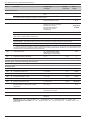
Document n° 1586-1 ~ 20/02/2013
FR
EN
IT
NL
DE
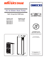
Air to Water Heat Pump
Split integrated DHW type
Outdoor unit
WO*G112LCT
WO*G140LCT
WO*K112LCT
WO*K140LCT
WO*K160LCT
Hydraulic unit
WG*G140DD6
WG*K160DD9
Installation and
operating manual
intended for professionals
To be saved for
future consultation
Fujitsu General (Euro) GmbH
Werftstrasse 20
40549 Düsseldorf - Germany
Subject to modifications without notice.
Non contractual document.
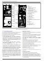
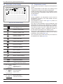
Air to Water Heat Pump (Split integrated DHW type)
""This device requires for its installation, the intervention of qualified personnel with a certificate of
capacity for handling refrigerants.
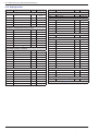
Contents
Description of the unit. . . . . . . . . . . . . . . . . . . . . . . . . . . . . . 4
Package. . . . . . . . . . . . . . . . . . . . . . . . 4
Definitions. . . . . . . . . . . . . . . . . . . . . . . 4
Specifications . . . . . . . . . . . . . . . . . . . . . 5
Description. . . . . . . . . . . . . . . . . . . . . . . 9
Operating principle . . . . . . . . . . . . . . . . . . 10
Installation. . . . . . . . . . . . . . . . . . . . . . . . . . . . . . . . . . . . 12
Regulation installation and maintenance conditions. .
Unpacking and reservations. . . . . . . . . . . . .
Receipt . . . . . . . . . . . . . . . . . . . .
Handling . . . . . . . . . . . . . . . . . . . .
Containment of refrigerant circuits . . . . . .
Accessories provided . . . . . . . . . . . . .
Installation position . . . . . . . . . . . . . . . . . .
Installation of the outdoor unit. . . . . . . . . . . .
Installation precautions. . . . . . . . . . . .
Outdoor unit positioning . . . . . . . . . . . .
Condensate drain hose. . . . . . . . . . . .
Installing the hydraulic unit . . . . . . . . . . . . . .
Installation precautions . . . . . . . . . . . .
Refrigeration connections. . . . . . . . . . . . . .
Rules and precautions. . . . . . . . . . . . .
Refrigeration connections. . . . . . . . . . .
Creating the flarings . . . . . . . . . . . . . .
Shaping the refrigeration pipes. . . . . . . .
Connecting the flared connections . . . . . .
Filling the installation with gas. . . . . . . . . . . .
Commissioning procedure. . . . . . . . . . .
Sealing test. . . . . . . . . . . . . . . . . .
Additional charge. . . . . . . . . . . . . . .
Pump down operation (Refrigerant collecting
operation) outdoor unit . . . . . . . . . . . .
-2-
12
12
12
12
12
12
13
13
13
14
14
15
15
16
16
17
17
17
17
19
19
20
21
21
Hydraulic connecting . . . . . . . . . . . . . . . . .
General. . . . . . . . . . . . . . . . . . . .
Connecting to the DHW circuit . . . . . . . .
Rinsing out the installation . . . . . . . . . .
Filling and purging the installation . . . . . . .
Connecting the Fan convector circuit. . . . .
Heating circulation pump speed settings . . . . . . .
Electrical connections. . . . . . . . . . . . . . . .
Characteristic of the electrical supply. . . . .
General remarks on electrical connections. .
Overview of all the electrical connections . . .
Cable section and protection rating. . . . . .
Electrical connections
on the single phase outdoor unit side. . . . .
Electrical connections
on the 3- phase outdoor unit side. . . . . . .
Electrical connections
on the hydraulic unit side. . . . . . . . . . .
Outdoor sensor . . . . . . . . . . . . . . . . . . . .
Room thermostat and/or remote control. . . . . . .
Installing a room sensor. . . . . . . . . . .
Installing a remote control. . . . . . . . . .
Commissioning . . . . . . . . . . . . . . . . . . . .
Configuring room thermostat (wireless). . . . . . .
Configuring remote control (wireless). . . . . . . .
22
22
23
24
24
24
25
26
26
26
27
27
28
29
30
34
34
34
34
34
35
35
Installation and operating manual "1586 - EN"
Air to Water Heat Pump (Split integrated DHW type)
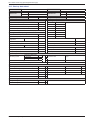
Regulation system. . . . . . . . . . . . . . . . . . . . . . . . . . . . . . . . 36
User interface, Remote control (option) and
Room thermostat (option). . . . . . . . . . . . . .
Description of the display . . . . . . . . . . . . . .
Temperature control. . . . . . . . . . . . . . . . .
Set to . . . . . . . . . . . . . . . . . . . . .
36
38
38
38
Parametering the setting . . . . . . . . . . . . . . .
General. . . . . . . . . . . . . . . . . . . .
Setting parameters . . . . . . . . . . . . . .
List of function lines
(settings, diagnosis, status). . . . . . . . . .
40
40
40
40
Overall hydraulic layout. . . . . . . . . . . . . . . . . . . . . . . . . . . . . 52
Electrical wiring diagrams. . . . . . . . . . . . . . . . . . . . . . . . . . . . 54
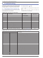
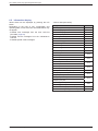
Troubleshooting . . . . . . . . . . . . . . . . . . . . . . . . . . . . . . . . . 58
Faults displayed on the hydraulic unit. . . . . . . . 58
Information display . . . . . . . . . . . . . . . . . . 59
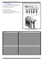
Faults displayed on the single phase outdoor unit . . 60
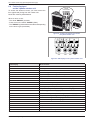
Faults displayed on the 3-phase outdoor unit. . . . 61
Maintenance of the installation . . . . . . . . . . . . . . . . . . . . . . . . . 62
Hydraulic checks . . . . . . . . . . . . . . . . . . .
Maintenance of the DHW tank. . . . . . . . . . . .
Emptying the hot water tank. . . . . . . . . .
Descaling. . . . . . . . . . . . . . . . . . .
62
62
62
62
Checking the outdoor unit. . . . . . . . . . . . . . 62
Electrical checks. . . . . . . . . . . . . . . . . . . 62
Maintenance . . . . . . . . . . . . . . . . . . . . . . . . . . . . . . . . . . . 63
Emptying the hydraulic unit . . . . . . . . . . . . . 63
Distribution valve . . . . . . . . . . . . . . . . . . . 63
ACI check . . . . . . . . . . . . . . . . . . . . . . 63
Instructions for the user. . . . . . . . . . . . . . . . . . . . . . . . . . . . . 63
Quick-start procedure . . . . . . . . . . . . . . . . . . . . . . . . . . . . . . 64
Start-up check-list. . . . . . . . . . . . . . . . . . 64
Before starting-up. . . . . . . . . . . . . . . 64
Starting-up. . . . . . . . . . . . . . . . . . . 65
Installation and operating manual "1586 - EN"
Settings sheet. . . . . . . . . . . . . . . . . . . . 66
Start-up data sheet . . . . . . . . . . . . . . . . . . 67
-3-
Air to Water Heat Pump (Split integrated DHW type)
Packing list
Heat pump (HP)
Model
Outdoor unit
Hydraulic unit
Model
Model
Waterstage High Power Integrated DHW 11 Single phase
WO*G112LCT
Waterstage High Power Integrated DHW 14 Single phase
WO*G140LCT
Waterstage High Power Integrated DHW 11 3-Phase
WO*K112LCT
Waterstage High Power Integrated DHW 14 3-Phase
WO*K140LCT
Waterstage High Power Integrated DHW 16 3-Phase
WO*K160LCT
Optional equipment
• 2nd circuit kit (code UTW-KZD*D)
for connecting 2 heating circuits.
• Regulation extension kit (code UTW-KRE*D)
to manage a 2nd heating circuit, swimming pool etc...
• Boiler connection kit (code UTW-KBD*D)
for connecting a boiler to the heat pump.
• Room thermostat (code UTW-C55*A),
Wireless room thermostat (code UTW-C58*D)
for correcting the ambient temperature.
• Remote control (code UTW-C75*A),
Wireless remote control (code UTW-C78*A)
for correcting the ambient temperature and
programming the heat pump.
• Swimming pool kit (code UTW-KSP*D).
• Cooling kit (code UTW-KCL*D).
WG*G140DD6
WG*K160DD9
Scope of application
This heat pump provides:
--Heating in winter,
--Control of two heating circuits*,
--Production of domestic hot water.
--Installation
with
boiler
connection*
as
a
supplementary heating for the coldest days.
or
--the addition of electrical back-ups*, for extra heating
on the coldest days.
--Cooling in summer* (for floor heating-cooling system
or fan-convectors).
--Heating the swimming pool*.
* :
These options require the use of additional kits
(see para "Optional equipment").
1 Description of the unit
1.1 Package
1.2 Definitions
• 1 package: Outdoor unit.
--Split: The heat pump consists of two elements
(an outdoor unit for outdoor and a hydraulic unit for
inside the dwelling).
--Air/water: The surrounding air is the energy source.
This energy is transmitted to the water in the heating
circuit by the heat pump.
--Inverter: The fan and compressor speeds are
modulated according to the heating requirements.
This technology enables you to save on energy and
operate on a single-phase power supply, whatever the
heat pump's output, by avoiding heavy intensities on
start-up.
--COP (coefficient of performance): This is the
relationship between the energy transmitted to the
heating circuit and electrical energy consumed.
• 1 package: Hydraulic unit and outdoor sensor.
-4-
Installation and operating manual "1586 - EN"
Air to Water Heat Pump (Split integrated DHW type)
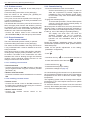
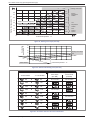
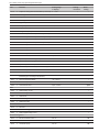
1.3 Specifications
Designation model Waterstage High Power
11 Single phase
14 Single phase
11 3-phase
14 3-phase
16 3-phase
Nominal heating performances (outdoor temperature / initial temperature)
Heat output
+7 °C / +35 °C - Floor heating system
kW
10,80
13,50
10,80
13,50
15,17
-7 °C / +35 °C - Floor heating system
kW
10,80
12,00
10,80
13,00
13,50
+7 °C / +45 °C - Low temperature radiator
kW
9,23
11,54
10,10
12,60
13,00
-7 °C / +45 °C - Low temperature radiator
kW
9,16
11,45
10,02
12,50
13,00
+7 °C / +55 °C - Radiator
kW
7,74
9,67
9,48
11,80
12,96
-7 °C / +55 °C - Radiator
kW
7,51
9,25
9,20
10,60
11,90
+7 °C / +35 °C - Floor heating system
kW
2,54
3,23
2,51
3,20
3,70
-7 °C / +35 °C - Floor heating system
kW
4,32
5,08
4,28
5,18
5,40
+7 °C / +45 °C - Low temperature radiator
kW
2,84
3,72
3,01
3,81
4,00
-7 °C / +45 °C - Low temperature radiator
kW
4,58
5,92
4,63
6,00
6,37
+7 °C / +55 °C - Radiator
kW
3,13
4,03
3,60
4,61
5,14
-7 °C / +55 °C - Radiator
kW
4,56
5,65
5,08
6,04
6,88
(+7 °C / + 35 °C)
4,25
4,18
4,30
4,22
4,10
25
8,5
9,5
10,5
14,2
3,7
4,8
5,5
Power absorbed
Coefficient of performance (COP)
Electrical characteristics
Supply voltage (50 HZ)
V
Maximum current for appliance
A
22
230
Nominal current
A
11,4
Maximum current of the electrical back-ups (heating)
A
400
13,05 / 26,1
13
kW
ajustable 3 or 6 kW (Single phase)
9 kW (3-phase)
Real power absorbed by the fan
W
2x100
Real power absorbed by the circulation pump
W
Maximum power absorption by the outdoor unit
W
Electrical back-up power DHW
W
1500
Maximum operating pressure Heating
bar
3
Maximum operating pressure Domestic hot water tank
bar
Power of the electrical back-ups (heating)
2x10⁴
70
5060
5750
5865
6555
7245
1460 / 2920
1650 / 3290
Hydraulic circuit
Hydraulic system flow rate 4°C<Δt<8°C (nominal conditions) min./max.
l/h
10
1170 / 2340
1460 / 2920
1170 / 2340
Various
Weight of outdoor unit
kg
Weight of hydraulic unit (empty / full of water)
kg
152/ 366
l
24 / 190
Water capacity of the hydraulic unit / the domestic tank
Noise level at 1 m 1 (hydraulic unit)
92
99
dB
39
Sound power level according to EN 12102 (hydraulic unit)
dB
Noise level at 5 m 1 (outdoor unit)
dB
42
43
39
41
42
dB
69
70
66
68
69
2
Sound power level according to EN 12102 (outdoor unit)
2
46
Heating system operating limits
Outdoor temperature mini/maxi
°C
-25 / +35
Initial max. heating water temperature Floor heating system
°C
45
Initial max. heating water temperature Low temperature radiator
°C
60
Diameter of gas pipes
inches
5/8
Diameter of liquid pipes
inches
Refrigeration circuit
Factory charge of refrigerant R410A 3
Maximum operating pressure
Minimum length of pipes
Maximum length of pipes
4
Maximum length of pipes 5 / Maximum level difference 5
2500
bar
41,5
m
5
m
15
m
20 / 15
Sound pressure level in (x)m of the device, 1,5m of the ground, the open field.
The sound power level is a laboratory measure of the emitted sound power but
contrary to the noise level, it doesn't correspond to the measure of the felt.
1
2
Installation and operating manual "1586 - EN"
3/8
g
3
4
5
Refrigerant R410A (as per the standard EN 378.1).
Factory charge of refrigerant R410A.
Taking into account the possible additional load of refrigerant R410A (see page 21)
-5-
Air to Water Heat Pump (Split integrated DHW type)
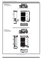
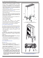
650
""Outside unit,
Model High Power
11 & 14 single phase
Air
370
Overflow hole (Ø 20)
4 Holes Ø 10)
Sight of lower part
31
330
12
900
77
Air
1290
Air
3/8”
5/8”
99
21
196
Front view
9
147
170
400
Side view
Top view
650
Air
370
""Outside unit,
Model High Power
11, 14 & 16 3-phase
Overflow hole (ø 20)
4 Holes (ø 10)
Sight of lower part
31
330
12
900
Air
1290
Air
9
21
400
Front view
Side view
Top view
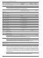
figure 1 - Dimensions in mm
-6-
Installation and operating manual "1586 - EN"
Air to Water Heat Pump (Split integrated DHW type)
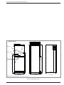
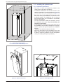
""Hydraulic unit
175
644
630
599
576
210
43
Heating return
47
Heating flow
1850
244
1840
1189
1296
DHW
DCW
698
648
Back view
Side view
103
Front view
Blockage in the hydraulic unit, see figure 13, page 15.
figure 2 - Dimensions in mm
Installation and operating manual "1586 - EN"
-7-
Air to Water Heat Pump (Split integrated DHW type)
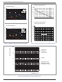
Outdoor sensor QAC34
Variable pressure
1 mbar = 10 mmCE = 100 Pa
mbar
43907
ext. in
600
2
500
2
4
4
6
7
10000
2490
400
300
200
338
2
100
0
1000
6
4
-50
0
0,5
1,5
1
-25
0
25
50
75
°C
2,5 m /h
3
2
Heat pump return sensor
Heat pump flow sensor
Constante pressure
32500
1 mbar = 10 mmCE = 100 Pa
mbar
30000
27500
ext. in
600
2
25000
2
4
4
6
7
22500
500
400
20000
7
17500
15000
4
300
12500
2
200
10000
7500
100
0
5000
0
0,5
1
1,5
2
2,5 m /h
3
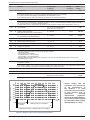
figure 3 - Hydraulic pressures and flow rates available
2500
0
°C
0
10
20
30
40
50
60
70
80
90
100
figure 4 - Ohmic values of the sensors (Hydraulic module)
Ohmic value (kΩ)
10000
- Compressor
- Discharge
- Condensation
1000
- Outside
100
- Evaporator outlet
- Evaporator center
- Compressor casing
10
1
-20 -10 0 10 20 30 40 50 60 70 80 90 100 110 120 130
Temperature °C
figure 5 - Ohmic values of the sensors (Outdoor unit)
-8-
Installation and operating manual "1586 - EN"
Air to Water Heat Pump (Split integrated DHW type)
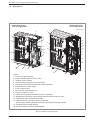
1.4 Description
""Model High Power
11 & 14 single phase
""Model High Power
11, 14 & 16 3-phase
WO*K1**LCT
1
3
1
3
5
4
2
4
2
14
7
15
13
5
13
15
14
9
9
7
11
8
6
11
12
6
10
8
12
10
Legend :
1 - Low-noise, high-output fan.
2 - Electric variable speed "inverter" motor.
3 - "Inverter" control module.
4 - Vacuum start (pump down) and control light.
5 - Connection terminal blocks (power and interconnection).
6 - Refrigerant accumulator bottle.
7 - Cycle reversing valve.
8 - Anti-corrosion treated bodywork.
9 - Electronic expansion valve.
10 - Noise and temperature insulated "inverter" compressor.
11 - Refrigeration connection valves (flared connectors) with protective caps.
12 - Holding tank with condensate drain hole.
13 - High-performance exchange surface evaporator ;
anti-corrosion treated hydrophilic aluminium fins and grooved copper tubes.
14 - Solenoid valve for liquid injection.
15 - Electric expansion valve for liquid injection.
figure 6 - Outdoor unit components
Installation and operating manual "1586 - EN"
-9-
Air to Water Heat Pump (Split integrated DHW type)
6
7
13
15
18
2
12
3
1
10
8
9
21
23
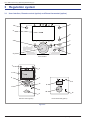
Legend :
1 - Electric box.
2 - Regulator / User interface.
3 - Start/stop switch.
4 - Hydraulic pumping unit.
5 - Distribution valve.
6 - Gas refrigeration connection.
7 - Liquid refrigeration connection.
8 - Condensation sensor.
9 - Drain valve.
10 - Safety valve.
11 - Safety thermostat.
12 - Manometer.
13 - Manual drainer.
14 - Expansion vessel.
15 - Condenser.
16 - Electrical back-ups DHW (Soapstone).
17 - ACI.
18 - ACI card.
Sensors :
21 - Water flow sensor.
22 - DHW sensor.
23 - Water return sensor.
14
4
5
22
9
11
17
16
9
figure 7 - Hydraulic unit components
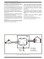
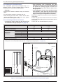
1.5 Operating principle
The heat pump transmits the energy contained in the
surrounding air into the dwelling to be heated.
The heat pump consists of four main elements, in which
a refrigerant fluid (R410A) circulates.
--In the evaporator (ref. 13, figure 6, page 9) :
The energy is taken from the surrounding air and is
transmitted to the refrigerant. Because it has a low
boiling point, it changes from the liquid state to the
vapour state, even in cold weather (down to -15 °C
outdoor temperature).
--In the compressor (ref. 10, figure 6, page 9) :
The vaporised refrigerant brought to high pressure
and takes on more calories.
--In the condenser (ref. 15, figure 7) :
The energy in the refrigerant is transmitted to the
heating circuit. The refrigerant returns to liquid state.
--In the expansion valve (ref. 9, figure 6, page 9) :
The liquefied refrigerant is brought back to low pressure
and returns to its initial temperature and pressure.
The heat pump is equipped with a controller, which
controls the room temperature based on the outdoor
temperature measurement and governed by the
temperature control. The room thermostat (option)
provides a corrective action for the temperature control.
--The hydraulic unit can be optionally fitted with an
electrical back-up system or boiler connection which
starts up in order to provide addtional heating during
the coldest periods.
- 10 -
• Regulation functions
--The heating circuit's initial temperature is controlled by
the temperature control.
--The power of the outdoor unit is modulated according to
flow heating temperature via the "inverter" compressor.
--Control of the electrical back-up heating.
--The daily timer program enables you to define
the periods for comfortable or reduced ambient
temperature.
--Summer/winter mode switchover is automatic.
--Control of the supplementary boiler* (option).
--The room thermostat (option)*: provides a corrective
action for the temperature control.
--Control of a second heating circuit*.
--Domestic hot water: Heating time programme, control
of the operation of the DHW circulation pump.
--Managing the cooling*.
--Control of swimming pool heating*.
* If the heat pump is equipped with optional equipment and the
associated kits.
• Protection functions
--Anti-legionella cycle for domestic hot water.
--Anti-corrosion protection with titanium anode (ACI).
--Frost protection: Frost protection cuts in if the lowtemperature point of the heating circuit falls below 5 °C
(provided that the heat pump's electrical power supply
is not interrupted).
Installation and operating manual "1586 - EN"
Air to Water Heat Pump (Split integrated DHW type)
• Domestic hot water (DHW) operating principle
Two domestic hot water (DHW) temperatures can be
parametered: nominal temperature (line 1610 to 55 °C)
and reduced temperature (line 1612 to 40 °C).
The default heat pump program (line 560, 561 and 562)
is set for nominal temperature from 0:00 to 5:00 and
from 14:30 to 17:00 and for reduced temperature for the
rest of the day. This optimizes electrical consumption
while ensuring comfortable availability of hot water.
Setting for reduced temperature can be useful to prevent
the DHW from switching on too often and for too long
during the day.
The production of domestic hot water (DHW) is triggered
when the temperature in the tank falls 7°C (setting from
line 5024) below the set temperature.
The heat pump produces the domestic hot water, which
is then additively heated, if required, by electrical backup heating inside the tank. To ensure a DHW setting
over 55°C, the electrical back-up heating or the boiler
must be left on.
Depending on how the parameter (1620) is set, nominal
temperature can be reached 24h/day or only at night or
depending on the heat pump program.
If the contract concluded with the energy provider
includes a subscription to day/night tariff, the electrical
backup is subordinate to the supplier’s power tariff and
the comfort temperature may only be reached at night.
If no particular contract is concluded, the comfort
temperature can be reached at any time, including
during the day.
The production of DHW takes priority over heating;
nevertheless the production of DHW is controlled by
cycles that control the times assigned to the heating
and the production of DHW in the event of simultaneous
demand.
A function to switch from "reduced" to "nominal"
is provided on the front of the user interface.
(see ref. 1, figure 42, page 36).
Anti-legionella cycles can be programmed.
• Fan convectors with integrated control system
Do not use a room sensor in the area.
PAC
HP
4 kW
Dt
Cn
Energy from the air
Ev
Heat produced
20 °C
Cp
COP 4
1 kW
Electrical
energy
consumed
HP - Heat pump
Ev - Evaporator
Cp - Compressor
Cn - Condenser
Dt - Expansion valve
figure 8 - Heat pump operating principle
Installation and operating manual "1586 - EN"
- 11 -
Air to Water Heat Pump (Split integrated DHW type)
2 Installation
2.1 Regulation installation
and maintenance conditions
2.2.3 Containment of refrigerant circuits
The appliance must be installed and the maintained by an
approved professional in accordance with the prevailing
regulations and code of practice, in particular:
--The legislation on the handling of refrigerants.
--Heating installation with floor heating system.
--Low voltage electrical installations - Rules.
2.2 Unpacking and reservations
2.2.1 Receipt
Carefully check, in the carrier's presence, the general
appearance of the appliances and check that the
outdoor unit is not laid on its side or back.
In the case of any dispute, state any appropriate
reservations to the carrier in writing within 48 hours and
send a copy of this letter to the After-Sales service.
2.2.2 Handling
The outdoor unit should not be laid on its side or back
during transport.
If not kept upright during transport, the appliance could
be damaged through displacement of the refrigerant
and deformation of the compressor suspension.
Any damage caused by transportation of the unit lying
down is not covered by the warranty.
If necessary the outdoor unit may be tilted only during
manual handling (to go through a door or use a staircase).
This operation must be conducted very carefully and
the appliance must be immediately restored to upright
position.
All refrigerant circuits fear contamination from dust and
moisture. If such pollutants introduced into refrigeration
circuit, they can contribute to degrade the reliability of
the heat pump.
""It’s necessary to ensure correct containment
connections and refrigerant circuits (hydraulic
unit, outdoor unit).
""In case of subsequent failure and expertise, the
finding of the presence of moisture or foreign
objects into the compressor oil would lead to
systematic exclusion of warranty.
--Check upon receipt that the fittings and the refrigeration
circuit caps mounted on hydraulic unit and outdoor unit
are properly seated and locked (impossible to loosen
bare hands). If this’s not the case, tighten them using
an against wrench.
--Check also that the refrigerant connections are
sealed (plastic caps or tubes crushed at the ends
and soldered). If the caps must be removed during
installation (tubes cut by example), put back them as
soon as possible.
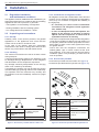
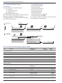
2.2.4 Accessories provided
Accessories provided with the outdoor unit (figure 9).
Accessories provided with the hydraulic unit (figure 10).
10
5
2
1
8
7
1
2
3
1
Elbow
2
Plug (x 2)
(Depending on the
model)
for draining away the
condensates
3
Hex / Allen key
to open the valves
34
figure 9 - Accessories provided with the outdoor unit
- 12 -
3
4
6
9
1
Dielectric fittings
2
DHW pipes
3
Gaskets
4
Outdoor sensor
7
Insulation right
8
9
Insulation conical to isolate the connections
and tubes
Insulation tape
10
Insulation tube
for connection to the DHW
circuit
to monitor the outside
temperature
figure 10 - Accessories provided with the hydraulic unit
Installation and operating manual "1586 - EN"
Air to Water Heat Pump (Split integrated DHW type)
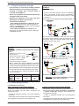
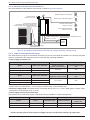
2.3 Installation position
2.4 Installation of the outdoor unit
The choice of the position for installation is particularly
important insofar as any later movement is a delicate
operation requiring the intervention of a qualified person.
Choose the site of the outdoor unit and the hydraulic
unit after discussion with the customer.
Observe the maximum and minimum distances between
the hydraulic unit and the outdoor unit (figure 19, page 18),
the guarantee of the performances and the system's
service life depend on this.
2.4.1 Installation precautions
The outdoor unit must only be installed outdoor
(outdoors). If a shelter is required, it must have
broad openings on the 4 walls and observe the
installation clearances (figure 11).
• Choose a site that is preferably sunny and sheltered
from strong cold predominant winds (mistral,
tramontana, etc…).
• The unit must be easily accessible for future installation
and maintenance work (figure 11).
• Ensure that it is possible to make the connections to
the hydraulic unit easily.
• The outdoor unit is able to withstand bad weather but
avoid installing in a position where it is likely to be
exposed to significant dirt or flowing water (under a
defective gutter for example).
150
200
200
1000
or more
Minimum
1500
1000
300
Max. 500
150
1000
or
more
Minimum
300
500
250
250
Max. 500
Minimum
250
250
or more
Minimum
250
300
250
250
or more
Minimum
1500
or more
Minimum
250
or more
500
1500
or more
Minimum
1500
250
250
or more
Minimum
150
1500
250
250
or
more
Minimum
500
Max.300
600
1000
2000
or more
Minimum
600
250
250
or more
Minimum
600
1500
3000
or
more
Minimum
figure 11 - Minimum installation clearances around outside unit (all models)
Installation and operating manual "1586 - EN"
- 13 -
Air to Water Heat Pump (Split integrated DHW type)
• Water may drain away from the outdoor unit when it
is operating. Do not install the appliance on a paved
terrace; choose a well-drained place (e.g. gravel
or sand). If the installation is in an area where the
temperature can be lower than 0°C for a long period,
check that the presence of ice does not present any
danger. A drainage pipe can also be connected to the
outdoor unit (figure 12, page 14).
• Nothing should obstruct the air circulation through the
evaporator and from the fan (figure 11).
• Keep the outdoor unit away from heat sources and
inflammable products.
• Make sure the appliance not disturb the surrounding
area or users (noise level, draught generated, low
temperature of the air being blown out, with the risk of
freezing plants in its path).
• The surface on which the appliance is installed must:
--be permeable (soil, gravel, etc),
--support its weight easily,
--provide a solid fixing and
--not transmit any vibration to the dwelling.
(Anti-vibratory blocks are available as an option).
• The wall bracket can not be used in conditions likely to
transmit vibrations, ground position is preferred.
* In regions subject to frequent snow,
(H) must be greater than the average snow layer.
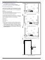
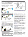
2.4.2 Outdoor unit positioning
The outdoor unit must be raised at least 50 mm above
ground level. In areas prone to snow, this height should
be increased but should not exceed 1,5 m (figure 12).
--Fasten the outdoor unit by means of screws and
rubber tightening or toothed lock washers to avoid
their coming loose.
""Warning
In the area with heavy snowfall, if the intake and outlet
of outdoor unit is blocked with snow, it might become
difficult to get warm and it is likely to cause of the
breakdown.
Please construct a canopy and a pedestral or place the
unit on high stand (local configured).
--Set the unit on a strong stand, such as one made of
concrete blocks to minimize shock and vibration.
--Do not set the unit directly on the ground because it
will cause trouble.
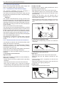
2.4.3 Condensate drain hose
(see figure 12).
If the use of a discharge pipe is imperative:
--Use the elbow provided (C) to connect a 16mmdiameter hose for draining away the condensate.
--Use the stopper or stoppers provided (B) to block the
opening of the condensate tank.
Allow for the condensate to flow away under the force of
gravity (waste water, rain water, gravel bed).
""If the installation is made in an area where
the temperature can be lower than 0°C for
a long period, provide the drain pipe with a
trace resistance to avoid it icing up. The trace
resistance must heat not only the pipe but
also the bottom of the appliance's condensate
collection tank.
- 14 -
B
C
B
4 holes
(ø 12 mm)
figure 12 - Positioning of the outside unit,
draining away the condensate
Installation and operating manual "1586 - EN"
Air to Water Heat Pump (Split integrated DHW type)
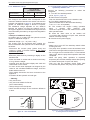
2.5 Installing the hydraulic unit
2.5.1 Installation precautions
• The room in which the appliance operates must
comply with the prevailing regulations.
300 mm
1800 mm
• To facilitate maintenance and to allow access to the
various components, we recommend that you provide
sufficient space all around the hydraulic unit (figure 13).
125 mm
• Be careful not to bring inflammable gas near to the
heat pump during its installation, in particular when
it requires brazing. The appliances are not fireproof
and should therefore not be installed in a potentially
explosive atmosphere.
--To avoid condensation inside the condenser, remove
the refrigerant circuit caps only when building the
refrigerant connections.
--If the refrigerant connection only occurs at the end of
the installation, be sure that the refrigerant circuit caps*
remain in place and tight throughout the installation
duration.
* (hydraulic unit side and outdoor unit side)
--After every intervention on the refrigeration circuit and
before final connection, take care to replace the plugs
in order to avoid any pollution from the refrigeration
circuit (The sealing with tape is prohibited).
1000 mm
figure 13 - Minimum installation clearances
around the hydraulic module
and distances to the combustible partitions
2
1
Front view
figure 14 - Open the front cover
Installation and operating manual "1586 - EN"
figure 15 - Removing the cover
- 15 -
Air to Water Heat Pump (Split integrated DHW type)
2.6 Refrigeration connections
""This appliance uses refrigerant R410A.
Comply with the legislation for handling refrigerants.
2.6.1 Rules and precautions
• After every intervention on the refrigeration circuit and
before final connection, take care to replace the plugs
in order to avoid any pollution from the refrigeration
circuit.
• Minimum necessary tools
--Set of manometers (Manifold) with hoses exclusively
reserved for HFCs (Hydrofluorocarbons).
--Vacuum gauge whith isolation valves.
--Vacuum pump specially for HFCs (use of a traditional
vacuum pump is authorized if, and only if, it is fitted
with a non-return valve on the suction side).
--Flaring tool.
--Pipe-cutter.
--Deburring tool.
--Wrenches.
--Refrigerant gas leak detector certified (sensitivity 5g/year).
Right DHW outlet of the HP
""Provision on using tools that have been in
contact with HCFCs (R22 for example) or CFCs.
""The manufacturer declines any liability with
regard to the guarantee if the above instructions
are not observed.
Left DHW outlet of the HP
Each side DHW outlet of the HP
55 mm
figure 16 - DHW outlet
- 16 -
Installation and operating manual "1586 - EN"
Air to Water Heat Pump (Split integrated DHW type)
• Flared connections
2.6.2 Refrigeration connections
""Lubrication with mineral oil (for R12, R22)
is forbidden.
--Only lubricate with polyolester refrigeration oil (POE).
If POE is not available, fit without lubrication.
The outdoor unit must be connected to the hydraulic
unit only with new copper pipes and connections
(refrigeration quality), insulated separately.
Comply with the pipe diameters and the permitted pipe
lengths (figure 19).
The minimum length of the refrigeration connections
is 5 m for correct operation.
The appliance will be excluded from guarantee if it is
used with refrigeration connections less than 5 m long.
If the refrigeration connections are exposed to
weathering or UV- and the insulation is not strong, it is
necessary to provide protection.
Manipulate the pipes and take them through walls with
protective plugs in place.
Coat the flared surface
with POE refrigeration oil.
Do not use mineral oil.
• Brazing on the refrigeration circuit (if necessary)
--Silver brazing (40% minimum recommended).
--Brazing only under dry nitrogen internal flux.
• To eliminate any filings in the pipes, use dry nitrogen
to avoid introducing any humidity that may adversely
affect the appliances operation. In general, take every
precaution to avoid humidity penetrating into the
appliance.
• Proceed to insulate the gas and liquid pipes to avoid
any condensation. Use pipe insulators resistant to
temperatures over 90°C. In addition if the humidity
level in areas where the refrigeration pipes are
installed is expected to exceed 70%, protect the pipes
with pipe insulators. Use an insulating material thicker
than 15mm if the humidity level is 70~80%, and an
insulating material thicker than 20mm if the humidity
exceeds 80%. If the recommended thicknesses are
not observed under the conditions described above,
condensation will form on the surface of the insulation
material. Lastly, take care to use pipe insulators
whose thermal conductivity is 0.045 W/mK or less
when the temperature is 20°C. The insulation must be
impermeable to resist the passage of steam during the
defrosting cycles (fibreglass wool is prohibited).
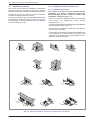
2.6.3 Creating the flarings
--Cut the pipe to an appropriate length with a pipe-cutter
without deforming it.
--Carefully deburr it, holding the pipe towards the bottom
to avoid introducing filings into the pipe.
--Remove the flared connection nut situated on the
valve to be connected and slip the pipe into the nut.
--Proceed to flare, letting the pipe overflow the flaring
tool.
--After flaring, check the condition of the working
radius (L). This must not show any scratch or trace of
any fracturing. Also check the dimension (B).
Holding wrench
B
Flaring tool
C
Hose
ø Hose
Flare
nut
L
Torque wrench
Designation
dimensions in mm
Tightening torque
Flare nut 9,52 mm (3/8")
32 to 42 Nm
Flare nut 15,88 mm (5/8")
63 to 77 Nm
L
B 0/-0,4
C
Plug (A) 3/8"
20 to 25 Nm
9,52 (3/8")
2,5 to 2,7
13,2
22
Plug (A) 5/8"
30 to 35 Nm
15,88 (5/8")
2,9 to 3,1
19,7
29
Plug (B) 3/8", 5/8"
10 to 12 Nm
figure 17 - Flaring for flare connections
Installation and operating manual "1586 - EN"
figure 18 - Tightening torque
- 17 -
Air to Water Heat Pump (Split integrated DHW type)
2.6.4 Shaping the refrigeration pipes
The refrigeration pipes must be shaped only on a
bending machine or with a bending spring in order to
avoid any risk of crushing or breaking them.
""Warning !
• Remove the insulation material locally to bend the
pipes.
• Do not bend the copper to any angle over 90°.
• Never bend pipes more than 3 times in the same
position otherwise traces of fracturing may appear
(from strain-hardening the metal).
2.6.5 Connecting the flared connections
""Connections must be made the day of the filling
the installation with gas (see para. 2.7, page 19).
HP model
""The refrigeration circuit is very sensitive to dust
and humidity: check that the area around the
connection is clean and dry before removing the
plugs protecting the refrigeration connectors.
--Remove the plugs from the pipes and the refrigeration
connections.
--Present the pipe to the flared connector and screw the
nut by hand while holding the connector with a wrench
until contact.
--Comply with the indicated tightening torques.
High Power single phase & 3-phase
Outdoor unit connections
Diameter
Refrigeration
connections
""Take particular care positioning the tube
opposite its connector so as not to risk damaging
the threads. A carefully aligned connector can
be fitted easily by hand without much force
being required.
gas
fluid
5/8"
3/8"
(D1) 5/8"
(D2) 3/8"
Minimum length (L)
5
Maximum length* (L)
15
Maximum length** (L)
20
Maxi level difference**(D)
15
Hydraulic unit connections
5/8"
3/8"
* : without additional charge of R410A.
** : Taking into account the possible additional load of refrigerant R410A (see para. 2.7.3, page 21).
Hydraulic unit
Outdoor unit
Flare nut
Flare nut
HP
Liquid
valve
Flare
nut
HP
L D
"Liquid" refrigeration connection
Diameter D2
Gas
valve
Flare
nut
“Gas” refrigeration connection
Diameter D1
figure 19 - Connecting the flared connections (Pipe diameters and permissible lengths)
- 18 -
Installation and operating manual "1586 - EN"
Air to Water Heat Pump (Split integrated DHW type)
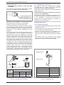
2.7 Filling the installation with gas
""This operation is reserved for installers familiar
with the legislation for handling refrigerants.
""Creating a vacuum with a vacuum pump is
essential (see ANNEX 1).
""Never use equipment used beforehand with any
refrigerant other than a HFC.
""Remove the refrigerant circuit caps only when
building the refrigerant connections.
""Unfavorables conditions :
- If the outdoor temperature is between +5 and
+10 °C, it’s obliged to have a vacuum gauge for
validate the pump down operation and use method
3 empty. (see ANNEX 2).
- If the outdoor temperature is below +5 °C,
it’s strongly not recommended to do the filling the
installation with gas.
ANNEX 2
Method 3 empty
--Connect the high pressure hose to the Manifold,
("Gas" connection). A valve must be mounted on
the flexible hose from the vacuum pump in order
to isolate it.
a) Pump down to the desired value (see table ANNEX 1),
Manometer kit
kit
JeuManometer
de
manomètres
(Manifold)
(Manifold)
(manifold)
Low
Basse Lo
pressure
pression
Hi
High
Haute
pressure
pression
Vacuum gauge
Vacuomètre
Connection
UE Liaison...
Liquid
liquide
gaz
Gas
MH
Vacuum
Pompe àpump
vide
b) Stop the vacuum pump, close the valve end of
the service hose (yellow). Connect the hose to the
expansion valve of the nitrogen bottle, inject 2 bars,
close the flexible hose valve,
Lo
ANNEX 1
Method for calibration and control of a vacuum
pump
Vacuum
--Check the oil level of the
gauge
Vacuomètre
vacuum pump.
Flexible
Clogged
Vacuum
flexible
--Connect the vacuum pump bouché
Pompe
pump
hose
à vide
with the vacuum gauge
according to the scheme.
--Pump down during 3 minutes.
--After 3 minutes, the pump reaches its threshold
value and the vacuum gauge needle does not move.
--Compare the obtained pressure with the value of the
table. Depending on the temperature, this pressure
must be less than the value indicated in the table.
=> If it’s not the case, replace the gasket, flexible
hose or the pump.
T °C
5°C<T<10°C
10°C<T<15°C
15°C < T
Pmax
- bar . .
- mbar
. . . 0.009 . . .
.....9.....
. . . 0.015 . . .
. . . . 15 . . . .
. . . 0.020. . .
. . . .20 . . . .
Hi
Nitrogen
Azote
High
Haute
pressure
pression
Liaison...
UE Connection
Liquid
liquide
Gas
gaz
MH
c) Reconnect the flexible hose to the vacuum pump,
turn on and gradually open the hose valve.
Lo
Hi
High
Haute
pressure
pression
Liaison...
UE Connection
Liquid
liquide
gaz
Gas
MH
d) Repeat this at least three times.
""Reminder : It’s strictly forbidden to perform
these operations with refrigerant.
2.7.1 Commissioning procedure
• Check before connecting
"Gas" connection control (large diameter).
--Connect the "Gas" connection to the outdoor unit.
--Blow dry nitrogen into the "Gas" connection and
observe this end:
If water or impurities emerge, use a new refrigerant
connection.
Otherwise, perform the flare and connect immediately
the refrigerant connection to the hydraulic unit.
Installation and operating manual "1586 - EN"
"Liquid" connection control (small diameter).
--Connect the "Liquid" connection to the outdoor unit.
--Blow dry nitrogen into "Gas" connection – condensor
- "Liquid" connection assembly and Observe this
end (Outdoor unit side).
If water or impurities emerge, use a new refrigerant
connection.
Otherwise, perform the flare and connect immediately
the refrigerant connection to the outdoor unit.
- 19 -
Air to Water Heat Pump (Split integrated DHW type)
• First seal test
--Remove the protective plugs (B) from the charging
hole (Schrader) in the "Gas" valve (large diameter).
--Connect the high pressure hose to the Manifold.
--Connect the bottle of nitrogen to the Manifold
(Use only dry nitrogen type U).
--Pressurize the refrigerant circuit with nitrogen
(10 bar maximum) ("Gas" connection – condensor "Liquid" connection assembly).
--Let the circuit under pressure for 30 minutes.
Refrigeration
connecxion
(Gas)
Refrigeration
connexion
Plug (A)
3-way valve
Hex / Allen key of 4 mm
Load orifice
Lo
Hi
Nitrogen
Azote
Max.max.
10 bar
10 bars
during 30 mn mini.
30 mn mini
High
Haute
pressure
pression
Liaison...
UE Connection
Liquid
liquide
Gas
gaz
Hi
High
Haute
pressure
pression
Closed
valve,
Vanne
fermée,
pressure control
Contrôle pression
Leak control
Contrôle
d’étanchéité
UE Liaison...
liquide
gaz
MH
--When the pressure is stable and leakage is excluded,
drain nitrogen letting a pressure above atmospheric
pressure (0,2 to 0,4 bar).
• Creating a vacuum and filling the refrigeration
connections with gas
--If necessary, calibrate the Manifold gauge to 0 bar.
Adjust the vacuum gauge to the atmospheric pressure
(around 1013 mbar).
--Connect the vacuum pump to the Manifold. Connect
a vacuum gauge if the vacuum pump is not equipped.
Lo
Hi
High
Haute
pressure
--Let the pump continue to operate for another
30 minutes minimum after reaching the vacuum.
--Close the Manifold valve and then stop the vacuum
pump without disconnecting any of the hoses in
place.
""If the outdoor temperature is between +5 and
+10 °C, use method 3 empty (see ANNEX 2).
--Remove the access plugs (A) from the valve controls.
--If an additional charge is requires, add the additional
charge before filling the hydraulic unit with gas. Please
refer to the para. "Additional charge", page 21
--First of all fully open the "Liquid" valve (small)
and then the "Gaz" valve (large) using a hex key
(counterclockwise
direction)
without
forcing
excessively against the stop.
--Remove the hose rapidly to the Manifold.
--Refit the 2 original caps (be sure they are clean) and
tighten them to the recommended tightening torque
(figure 18, page 17). The sealing is performed in the
caps only metal to metal.
The outdoor unit does not contain any additional
refrigerant, enabling the installation to be purged.
Flushing is strictly forbidden.
2.7.2 Sealing test
pression
Vacuum
gauge
Vacuomètre
Liaison...
UE Connection
Liquid
liquide
gaz
Gas
MH
Vacuum
Pompepump
à vide
--Create a vacuum until the residual pressure* in the
circuit falls below the value given in the following table.
(* measured with the vacuum gauge).
T °C
5°C<T<10°C
10°C<T<15°C
15°C < T
Pmax
- bar . .
- mbar
. . . 0.009 . . .
.....9.....
. . . 0.015 . . .
. . . . 15 . . . .
. . . 0.020 . . .
. . . .20 . . . . .
- 20 -
Plug (B)
figure 20 - Connexion of the hose on the "Gaz" valve
MH
--Search for leaks with a leak detector product, repair
and repeat the test.
Lo
Service hose (blue)
High
hosepush-button
(red)
fittedpressure
with valve
The sealing test must be performed with a certified gas
detector (sensitivity 5g/year).
Once the refrigeration circuit has been gassed as
described above, check that all the refrigeration connectors
are gas-tigh (4 connectors). If the flarings have been made
correctly, there should be no leaks. Eventually, check the
tightness of the refrigerant valves caps.
""If there is a leak:
--Bring the gas into the outdoor unit (pump down).
The pressure should not drop below atmospheric
pressure (0 bar to read on Manifold) so as not to
contaminate the recovered gas with air or moisture.
--Make the connection again.
--Repeat the commissioning procedure.
Installation and operating manual "1586 - EN"
Air to Water Heat Pump (Split integrated DHW type)
2.7.3 Additional charge
50 g of R410A
per additional meter
Length of
the connections
15 m
20 m max.
Additional charge
none
250 g
The charge in the outdoor units corresponds to the
maximum distances between the outdoor unit and the
hydraulic unit defined in page 18. If the distances are
greater, an additional charge of R410A is required.
The additional charge depends on the distance
between the outdoor unit and the hydraulic unit for
each type of appliance. The additional charge of R410A
must necessarily be made by an approved refrigeration
engineer.
• Example of additional charge :
An outdoor unit 17 m away from the hydraulic unit will
require an additional charge of :
Additional charge = (17 - 15) x 50 = 100 g.
The charge must be introduced after creating the
vacuum and before the hydraulic unit is filled with gas,
as follows :
--Disconnect the vacuum pump (yellow hose) and
connect a bottle of R410A instead in the liquid
extraction position.
--Open the bottle’s valve.
--Bleed the yellow hose by loosening it slightly on the
Manifold side.
--Place the bottle on scales with a minimum accuracy
of 10 g. Note the weight.
--Carefully open the blue valve slightly and check the
value shown on the scales.
--As soon as the value displayed has dropped by the
value for the calculated additional charge, close the
bottle and disconnect it.
--Then rapidly disconnect the hose connected to the
appliance.
--Proceed to fill the hydraulic unit with gas.
2.7.4 Pump down operation (Refrigerant collecting
operation) outdoor unit
Perform the following procedures to collect the
refrigerant.
--1- Turn OFF the start/stop switch
(ref. 3, figure 7, page 10).
--2- Remove the front panel.
Then turn ON the DIP SW 1 on the interface card.
--3- Turn ON the start/stop switch.
(Green and Red LED on the board start flashing ;
1 sec. on / 1 sec. off repeated).
--4- The outdoor unit begins cooling operation
about
3
minutes
after
switching
ON.
Close the "Liquid" valve on the outdoor unit 1 minute
after operation starts.
--5- Close the "Gas" valve on the outdoor unit
1-2 minutes after closing the "Liquid" valve, while the
outdoor unit keeps running.
--6- Disconnect the power supply.
Remarks :
--Make sure to turn OFF the start/stop switch before
touching DIP SW.
--The pump down operation cannot be activated even
if DIP SW is changed while heat pump's power is on.
--Do not forget to turn back DIP SW 1 on the interface
card to OFF, after the pump down operation has been
completed.
--When the pump down operation is repeated,
temporarily turn OFF the start/stop switch after opening
the closed valves (both "Liquid" and "Gas").
--Then turn ON the start/stop switch again after
2-3 minutes and perform the pump down operation.
""Warning
• Only use R410A !
• Only use tools suitable for R410A
(set of manometers).
Interface card
• Always charge in the fluid phase.
• Never exceed the length or the maximum difference
in level.
DIP SW
LED2
(green)
Gas
LED1
(red)
R410A
ON
OFF
Liquid
figure 21 - "Gas" bottle R410A
Installation and operating manual "1586 - EN"
figure 22 - Location of DIP switches and diodes
on the hydraulic unit interface card
- 21 -
Air to Water Heat Pump (Split integrated DHW type)
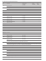
2.8 Hydraulic connecting
2.8.1 General
The connection must comply with good trade practice
according to local building regulations.
The heating circulating pump is built into the hydraulic unit.
Connect the central heating pipes to the appliance,
complying with the direction of circulation.
The pipe between the heat pump and the heat collector
must be at least one inch in diameter (26x34 mm).
Calculate the diameter of the pipes according to the
flow rates and the lengths of the hydraulic systems.
Tightening torque: 15 to 35 Nm.
Use union connectors to facilitate removing the hydraulic
unit.
Preferentially use connection hoses to avoid transmitting
noise and vibrations to the building.
Connect the drains from the drain valve and the safety
valve to the main sewer system.
Verify the correct functioning of the expansion system.
Control the vessel pressure (precharge 1 bar) and the
safety valve setting.
Reminder: Seal everything when fitting in accordance
with prevailing trade practice for plumbing work:
--Use suitable seals (fibre seals, o-rings).
--Use Teflon tape or hemp.
--Use sealing paste (synthetic depending on the case).
The use of glycol is not necessary. If you are using a
glycol/water mix, provide for an annual check on the
quantity of glycol. Use monopropylene glycol only.
Never use monoethylene glycol.
""In certain installations, the presence of different
metals can cause corrosion problems; the
formation of metal particles and sludge in the
hydraulic circuit is then seen.
""In this case, it is advisable to use a corrosion
inhibitor in the proportions indicated by its
manufacturer.
--Please refer to the chapter "Treatment of domestic
and heating water" in our price catalogue.
""It is also necessary to ensure that the treated
water does not become aggressive.
R1
Ø 26x34
1" Male
D
Ø 20x27
3/4" Male
MT
Legend:
CAR
CAR : Non-return valve.
D : Shut-off.
GS : Safety unit.
MT : Thermostatic mixer valve.
GS
R1 : Heating circuit.
figure 23 - Overall hydraulic layout
- 22 -
Installation and operating manual "1586 - EN"
Air to Water Heat Pump (Split integrated DHW type)
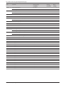
2.8.2 Connecting to the DHW circuit
Install dielectric fittings and DHW pipes on the tank
(see figure 24). Insulate DHW pipes with included
insulation.
""Be sure to put the DHW sensor at the bottom of
the thermowell DHW.
On the cold water inlet, place a safety unit rated
(from 7 to 10 bars - required by local regulations)
and connected to a drain pipe leading to the sewers.
Operate the safety unit according to manufacturer's
specifications.
Connect the safety valve evacuation to the drain.
We recommend that a thermostatic mixer be placed on
the hot water outlet.
1
2
3
4
5
6
7
8
9
10
11
Legend:
1. "Liquid" refrigeration connection.
2. "Gas" refrigeration connection .
3. Heating return (1 circuit).
4. Heating flow (1 circuit).
5. Stop valve (not supplied).
6. DHW exit (domestic hot water).
7. DCW entry (domestic cold water).
8. Shut-off (not supplied).
9. Filling.
10. Safety unit (not supplied).
11. Connecting to the drain with the siphon.
- Bleed tap evacuation.
- Safety valve evacuation.
figure 24 - DHW pipes mounting
Installation and operating manual "1586 - EN"
figure 25 - Connections
- 23 -
Air to Water Heat Pump (Split integrated DHW type)
2.8.3 Rinsing out the installation
2.9 Thermal insulation
Before connecting the hydraulic unit to the installation,
rinse out the heating system correctly to eliminate
any particles that may affect the appliance's correct
operation.
Do not use solvents or aromatic hydrocarbons (petrol,
paraffin, etc.).
In the case of an old installation, provide a sufficiently
large decanting pot with a drain on the return from the
boiler and at the lowest point in the system in order to
collect and remove the impurities.
Add an alkaline product to the water and a dispersant.
Rinse the installation several times before filling it
definitively.
Install the thermal insulation kit on the metal parts to
avoid the inconvenient effects of condensation.
• 1 - Install the straight insulating sleeves on the
exchanger’s heating fittings.
• 2 - Install the conical insulating sleeves on the
exchanger’s refrigeration fittings.
• 3 - Place the insulating adhesive tape on all the piping
fittings.
2.8.4 Filling and purging the installation
Check the pipe fixings, the tightness of the connectors
and the stability of the appliance.
Check the direction in which the water is circulating and
that all the valves open.
Proceed to fill the installation.
Do not operate the circulating pump while filling. Open all
the drain valves in the installation and the bleeder valve
for the hydraulic unit (P) to remove the air contained in
the conduits.
Close the drain and bleeder valves and add water until
the pressure in the hydraulic circuit reaches 1 bars.
Check that the hydraulic circuit has been purged correctly.
Check there is not a leak.
After the "Start-up" stage (see page 34), once the
machine has started, purge the hydraulic unit again
(2 litres of water).
""Precise filling pressure is determined by the
manometric height of the installation.
2.8.5 Connecting the Fan convector circuit
1
2
Heat pump > 11 kW: It must be installed on this circuit a
buffer tank (minimum capacity: 50 liters).
P
figure 26 - Hydraulic module bleeder valve
- 24 -
figure 27 - Thermal insulation
Installation and operating manual "1586 - EN"
Air to Water Heat Pump (Split integrated DHW type)
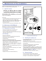
2.10 Heating circulation pump
speed settings
1 mbar = 10 mmCE = 100 Pa
mbar
Variable pressure
ext. in
600
2
500
The circulator varies the manometric height
according to the flowrate.
2
4
4
6
7
Recommended for a system equipped with
radiators (particularly any system with
thermostatic valves).
400
300
6
4
200
2
100
0
0
0,5
1,5
1
2,5 m /h
3
2
ext. in
2
2
4
4
6
7
Do not use this area.
1 mbar = 10 mmCE = 100 Pa
mbar
ext. in
600
2
2
4
4
6
7
500
400
7
4
300
Constant pressure
2
200
100
0
0
0,5
1,5
1
2
2,5 m /h
3
The circulation pump maintains the
manometric height constant whatever the
flow rate.
Recommended for a system with constant
pressure drop like a floor heating system.
figure 28 - Hydraulic pressures and flow rates available
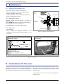
Circulation pump sticking or blocked:
If the motor is blocked, a start cycle is launched.
If the motor remains blocked it will be permanently
stopped.
ext. in
2
2
4
4
6
7
""Cut off the electricity supply from the circulation
pump for 30 seconds in order to release and
authorise another start cycle.
4
6
2
ext. in
2
7
4
figure 29 - Pump dial
Installation and operating manual "1586 - EN"
- 25 -
Air to Water Heat Pump (Split integrated DHW type)
2.11 Electrical connections
Ensure that the general electrical power supply has
been cut off before starting any repair work.
2.11.1 Characteristic of the electrical supply
The electrical installation must be conducted in
accordance with the prevailing regulations.
The electrical connections must only be made when all
the other fitting operations have been completed (fixing,
assembly, etc.).
""Warning !
The contract concluded with the energy provider must
be sufficient not only to cover the heat pump's power but
also the combined sum of all the appliances likely to be
operating at the same time. When the power is too low,
check with your energy provider the value subscribed to
in your contract.
Never use a socket for the power supply.
The heat pump must be supplied with power by special
protected leads from the electric panel via 2-pole circuit
breakers specially dedicated to the heat pump, Curve D
for the outdoor unit, curve C for the electrical heating
and domestic water back-ups (see tables on page 27).
The electrical installation must necessarily be equipped
with a 30mA differential protection.
This appliance is designed to operate under a nominal
voltage of 230 V or 400 V +/- 10%, 50 Hz (according to
model).
2.11.2 General remarks on electrical connections
It is essential to maintain the live-neutral polarity when
making the electrical connections.
Tighten the screws on the terminal blocks perfectly.
Unsufficient tightening can cause overheating, leading
to breakdown or even a fire.
Tighten the cables using the cable glands to prevent the
conductors from disconnecting accidentally.
Connection to Earth and Earth bonding continuity are
essential.
• Connecting to screw terminals
Rigid wires (A)
Rigid wires are always preferable for fixed installations,
particularly in a building.
--Always select a wire that complies with the prevailing
standards.
--Strip away around 25 mm from the end of the wire.
--With round end pliers, form a loop with a diameter
corresponding to the tightening screws on the terminal.
--Tighten the terminal screw firmly onto the loop created.
Flexible wires (B)
H07RNF type (or superior quality) flexible wire can be
used with certain precautions:
--Strip away around 10 mm from the end of the wire.
--With tightening pliers, fit a round tag with a diameter
corresponding to the terminal screw's diameter on the
end of the wire.
--Tighten the tag firmly onto the terminal with a
screwdriver. We strongly advise against using flexible
wires without round tags.
--Always protect the cables when passing them through
cable clamps with PVC protective conduit 0,5 to 1 mm
thick.
A : Rigid wires
B : Flexible wires
Round terminal
tightened
Loop
25 mm
10 mm
Special screw
and
washer
Terminal
block
• Connecting to regulation cards
--Remove the corresponding connector and make the
connection.
Pre-cabled bundle connector and/or Screw connector
• Connecting to spring terminals
Rigid wires
--Strip away around 10 mm from the end of the wire.
--Slide the wire into the opening provided for this
purpose.
--Push the spring with a screwdriver so that the wire
enters the cage.
--Remove the screwdriver and then check that the wire
is jammed in the cage by pulling on it.
Flexible wires
--Use the ends and proceed as before.
3
2
- 26 -
1
Installation and operating manual "1586 - EN"
Air to Water Heat Pump (Split integrated DHW type)
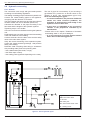
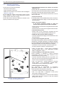
2.11.3 Overview of all the electrical connections
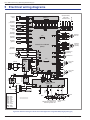
The wiring diagram for the hydraulic unit is shown in detail on figure 50, page 56.
Wireless remote control (option)
Outdoor sensor
Cable 2 x 0,75 mm²
or
Wireless room thermostat (option)
or
Interconnection between
the outdoor unit and the hydraulic unit :
Phase, Neutral, Earth, Communication bus
Cable 4 x 1,5 mm²
Remote control (option)
Cable 3 x 0,5 mm²
or
Room thermostat (option)
Cable 2 x 0,5 mm²
DHW power supply
(Phase, Neutral, Earth)
Cable 3 x 1,5 mm²
Power supply to the electrical back-ups
(See table below)
Electric
panel
General electrical supply
(See table below)
figure 30 - Overall layout of the electrical connections for a simple installation (1 heating circuit)
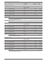
2.11.4 Cable section and protection rating
The cable sections are given for information purposes only and do not exempt the installer from checking that these
sections correspond to the requirements and comply with the prevailing standards.
• Power supply to outdoor unit:
Heat pump (single phase)
Model
Electricity supply 230 V - 50 Hz
Maxi. power absorbed
High Power 11 single phase
5060 W
High Power 14 single phase
5750 W
Cable connection
(phase, neutral, earth)
Curve D circuit breaker
size
3 x 6 mm²
32 A
Heat pump (3-phase)
Model
Electricity supply 400 V - 50 Hz
Maxi. power absorbed
High Power 11 3-phase
5865 W
High Power 14 3-phase
6555 W
High Power 16 3-phase
7245 W
Cable connection
(3 phases, neutral, earth)
Curve D circuit breaker
size
5 x 2,5 mm²
20 A
• Interconnection between the outdoor unit and the hydraulic unit: The hydraulic unit is powered by the outdoor
unit by means of a cable with 4 x 1,5 mm² (phase, neutral, earth, communication bus).
• Electricity supply DHW: The DHW section is powered directly via a 3 x 1,5 mm² cable (phase, neutral, earth).
Protection by circuit breaker (16 A, curve C).
• Power supply to the electrical back-ups:
The hydraulic unit contains two stages of electrical back-ups installed in a heat exchange tank.
Heat pump (HP)
Model
High Power single phase
High Power 3-phase
Electrical back-ups
Power supply to the electrical back-ups
Power
Nominal current
Cable connection
Curve C circuit
breaker size
2 x 3 kW
26,1 A
3 x 6 mm²
32 A
9 kW
3 x 13 A
4 x 2,5 mm²
20 A
""Ensure that the general electrical power supply has been cut off before starting any repair work.
Installation and operating manual "1586 - EN"
- 27 -
Air to Water Heat Pump (Split integrated DHW type)
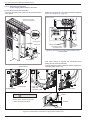
2.11.5 Electrical connections
on the single phase outdoor unit side
Access to the connection terminals:
--Remove the front panel. Remove the screws and the
front panel.
--Make the connections in accordance with the diagram
figure 32 and figure 41, page 33.
Terminal block
Remove the screws
and push downwards
Terminal
block
Service panel
Valve cover
General
electrical
supply
Interconnection between
the outdoor unit and
the hydraulic unit
figure 32 - Connections to sinlge phase outdoor unit’s
terminal block
Hook (4places)
--Use cable clamps to prevent the conductors from
being disconnected accidentally.
--Use the mounting plate to hold the cables against the
insulating plate. (figure 33).
figure 31 - Access to sinlge phase outdoor unit’s
terminal block
2
1
3
Cable clip
Cover plate
Insulation (seal)
Power supply
cable and
connection cable
CAUTION
Cover plate
Cables
Secure cables so that they are not in
contact with pipes and valves.
Release
Gas valve
figure 33 - Finalisation of connection to single phase outdoor unit
- 28 -
Installation and operating manual "1586 - EN"
Air to Water Heat Pump (Split integrated DHW type)
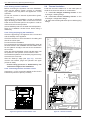
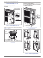
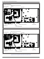
2.11.6 Electrical connections
on the 3- phase outdoor unit side
Access to the connection terminals.
--Remove the front panel. Remove the screws and the
front panel.
--Use cable clamps to prevent the conductors from
being disconnected accidentally.
--Fill in the space where the cables enter the outdoor
unit with the insulating plate.
Remove the screws
and push downwards
Terminal
block
Cable
clamps
Front panel
figure 34 - Access to 3-phase outdoor unit’s
terminal block
--Make the connections in accordance with the diagram
figure 37, page 26.
Cables
(supply and
interconnection)
figure 36 - Finalisation of connection
to 3-phase outdoor unit
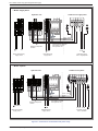
Terminal
block
1 2 3 L1 L2 L3 N
INDOOR UNIT
Interconnection between
the outdoor unit and the
hydraulic unit
POWER
General electrical
supply
Lateral side
Back
figure 35 - Connections to 3-phase outdoor unit’s
terminal block
Front
Underneath
figure 37 - Location of electrical cables and
refrigeration connections to 3-phase outdoor unit
Installation and operating manual "1586 - EN"
- 29 -
Air to Water Heat Pump (Split integrated DHW type)
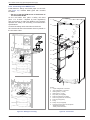
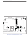
2.11.7 Electrical connections
on the hydraulic unit side
Access to the connection terminals:
--Remove the front panel.
--Open the power control box.
--Make the connections in accordance with the diagram
(figure 41, page 33).
Do not place the sensor lines and the sector supply
lines in parallel in order to avoid interferences due to
voltage points in the sector supply.
Ensure that all the electrical cables are housed in the
spaces provided for this purpose.
• Interconnection between the outdoor unit and the
hydraulic unit
Comply with the correspondence between the markings
on the hydraulic unit's terminals and those on the outdoor
unit when connecting the interconnection cables.
A connection error could cause the destruction of one or
other of the units.
• Electrical back-ups
If the heat pump is not installed with a boiler connection:
--Connect the electrical supply for the back-ups to the
electrical panel.
• Boiler connection (option)
""If the boiler connection option is used, the
electric boost option must not be connected.
--Please refer to the instructions supplied with the boiler
connection kit.
--Please refer to the instructions supplied with the boiler.
• Second heating circuit
--Please refer to the instructions supplied with the
second circuit kit or/and Regulation extension kit.
• DHW tank with electrical back-up heating
--Connect the electrical supply for the DHW tank to the
electrical panel.
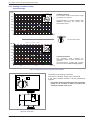
• Contract with the power provider
The heat pump's operation can be controlled to suit special
contracts (e.g. off-peak, day/night). In particular, domestic
hot water (DHW) at Nominal temperature will be produced
during the off-peak hours when electricity is cheaper.
--Connect the "Power Provider" contact to input EX2.
--Set the parameter (1620) to "Off-peak hours".
• 230V on input EX2 = "Peak hours" information
activated (Base setting / Line modification possible
5983, Configuration menu).
• Power shedding or EJP (peak day removal)
Power limitation is intended to reduce electrical
consumption when this is too high compared to the
contract with the power provider.
--Connect the power limiting device to input EX1, the
back-ups for the heat pump and the DHW stop in the
event of over-consumption by the dwelling.
• 230 V on input EX1 = power limitation in progress
(Base setting / Line modification possible 5981,
Configuration menu) (Operating line 2920).
• External faults the heat pump
Any component of carryforward of information
(thermostat, pressure switch, etc.) may signal an
external problem and stop the heat pump.
--Connect the external component to input EX3.
• 230 V on input EX3 = stoppage of heat pump
(the system displays Error 369).
figure 38 - Location of electrical cables
at the rear of the hydraulic unit
- 30 -
• In the case of a heated floor, connect the floor heating
safety device into the connector of the floor heating
pump (X12 or X110).
Installation and operating manual "1586 - EN"
Air to Water Heat Pump (Split integrated DHW type)
Power shedding or EJP
(peak day removal)
Tariffs, peak times/off-peak times,
day / night
EX1
EX2
EX3
External fault
X60
X11
Wireless remote
control**
External component
contact* (faults, load
shedder, power meter)
X84
X86
M B9
B2 M B1 3 2 1
L
3
M B2 B1
* If the control device does not provide a potential-free contact,
the contact must be relayed to create equivalent wiring.
In all cases, please refer to the instruction manuals for the external
components (load shedder, power meters) to create the wiring.
** Option
The connection of terminal 3 of the remote control is not mandatory
(lighting of the remote control).
3 2 1
2 1
or
Outdoor
sensor
2 1
or
Room
Room
thermostat** thermostat**
Remote
control**
figure 39 - Connections to the heat pump regulator (accessories and options)
Installation and operating manual "1586 - EN"
- 31 -
Air to Water Heat Pump (Split integrated DHW type)
""Model single phase
Electrical Back-up Terminal blocks
+ Relays
Safety thermostat
HP regulator
L N
L
2
N
4
230 V
Cable grommet (power)
Interface card
Cable grommet (sensors)
Relay
+ DHW Terminal blocks
Terminal blocks
""Model 3-phase
Electrical Back-up Terminal blocks
Safety thermostat
Solid state relay
L N
L
2
N
HP regulator
4
230 V
Cable grommet (power)
Terminal blocks
Cable grommet (sensors)
Relay
+ DHW Terminal blocks
Interface card
figure 40 - Access to hydraulic model electric box and description
- 32 -
Installation and operating manual "1586 - EN"
Air to Water Heat Pump (Split integrated DHW type)
""Model single phase
Hydraulic unit
1 2 3
5
4
Outdoor unit single phase
6
L N
L
2
N
230 V
Green / yellow
Brown
Blue
Red
Interconnection between
the outdoor unit and
the hydraulic unit
External component
contact *
N
L
4
LN
Back-Up Electricity
supply 230 V
L N
DHW Electricity
supply 230 V
Electricity supply
230 V single phase
""Model 3-phase
Hydraulic unit
1 2 3
1
2
3
4
L1 L2 L3
5
4
5
Outdoor unit 3-phase
1
6
2 3 L1 L2 L3 N
6
COMMUN
L N
L
2
230 V
4
Green / yellow
Brown
Blue
Red
Interconnection between
the outdoor unit and
the hydraulic unit
External component
contact *
L1 L2 L3
N
LN
Back-Up Electricity
supply 400 V
DHW Electricity
supply 230 V
L1 L2 L3 N
Electricity supply
400 V 3-phase
figure 41 - Connection to terminal block and power relays
Installation and operating manual "1586 - EN"
- 33 -
Air to Water Heat Pump (Split integrated DHW type)
2.12 Outdoor sensor
2.14 Commissioning
The outdoor sensor is required for the heat pump to
operate correctly.
Consult the fitting instructions on the packaging.
Place the sensor on the coldest part, generally the
northern or north-eastern side.
In any case, it must not be exposed to the morning sun.
It must be installed so as to be easily accessible but at
least 2,5 m from the floor.
It is essential that it avoid any sources of heat such as
flues, the upper parts of doors and windows, proximity
to extraction vents, the underneath of balconies and
under-eave areas, which would isolate the sensor from
variations in the outdoor air temperature.
--Connect the outdoor sensor to the connector X84
(terminals M and B9) on the heat pump control board.
--Close the installation's main circuit breaker.
On first commissioning (or in winter), in order to
allow the compressor to pre-heat, engage the
installation's main circuit breaker (power supply
to the outdoor unit) some hours before starting
up the tests.
--Engage the start/stop switch.
To ensure that inputs EX1, EX2 and EX3 operate
correctly: Check that the live-neutral polarity of
the electrical supply is correct.
When the power is switched on and every time that the
ON/OFF button is switched off and then switched on
again, the outdoor unit will take approximately 4 minutes
to start up, even if the setting is requesting heating.
The display can show error 370 when the
appliance (re)starts. Do not be concerned,
the communication between the outdoor and
hydraulic unit will re-establish itself in a few
moments.
During the regulator initialisation phase, the display
shows all the symbols and then "Data, update" and then
"State heat pump".
--Make all the specific adjustments to the setting.
(Installation configuration):
2.13 Room thermostat
and/or remote control
The room thermostat (remote control) is optional.
Consult the fitting instructions on the packaging.
The sensor must be installed in the living room area on
a very uncluttered wall. It must be installed so as to be
easily accessible.
Avoid direct sources of heat (chimney/flue, television,
cooking hobs), draughty areas (ventilation, door, etc.).
Air leaks in the seals in the constructions are often
translated into cold air blowing through the electrical
conduits. Lag the electrical conduits if there is a cold
draught on the back of the IR sensor.
2.13.1 Installing a room sensor
OK
--Press
.
--Hold down the key
for 3s and select the level of
access used with the aid of the knob
.
OK
• Room thermostat
--Connect the sensor to the X86 connector of the heat
pump’s regulator board using the connector provided
(terminals 1, 2).
--Confirm with the key
.
--Parameter the heat pump's setting
(Consult the settings' list page 35).
• Wireles room thermostat
--Connect the wireless room thermostat to the connector
X60.
On commissioning (or the case of error 10), the electrical
back-up heaters are liable to start up even if the outdoor
temperature at the time is above the heaters’ trigger
temperature.
The regulating system uses an average initial outdoor
temperature of 0°C and requires some time to update
this temperature.
To avoid this situation, the sensor must be connected
correctly. Re-initialise parameter 8703 (commissioning
level, consumer diagnostic menu).
2.13.2 Installing a remote control
• Remote control
--Connect the remote control to the X86 connector of
the heat pump’s regulator board using the connector
provided (terminals 1, 2 and 3).
• Wireles remote control
--Connect the wireless
connector X60.
- 34 -
remote
control
to
the
Installation and operating manual "1586 - EN"
Air to Water Heat Pump (Split integrated DHW type)
2.15 Configuring room thermostat (wireless)
To configure the room thermostat and connect it to the
appropriate heating zone:
--Hold down the presence key for more than 3 seconds.
The room thermostat displays RU and a number flashes.
--Turn the wheel to choose the zone (1, 2).
--If the installation is fitted with 2 room
thermostats,
--First connect one room thermostat and configure
it in zone 2,
--Then connect the other room thermostat and
configure it as default in zone 1.
--Hold down the presence key; the room
thermostat displays P1 and a flashing number.
1: Automatic recording: a correction of the setting
with the button is adopted without any particular
confirmation (timeout) or by pressing the mode key.
2: Recording with confirmation: a correction of the
setting with the button is not adopted until the mode
key is pressed.
--Press the presence key again; the room thermostat
displays P2 and a flashing number.
0: OFF: all the operating elements are engaged.
1: ON: the following operating elements are locked:
- Switching over the heating circuit's operating
mode,
- Adjusting the comfort setting,
- Changing the operating level.
The room thermostat displays OFF for 3 seconds when
a locked button is pressed.
2.16 Configuring remote control (wireless)
During commissioning, after an initialisation period of
approx. 3 minutes, the user’s language must be set:
OK
--Press
.
--Choose menu "Operator section".
--Choose language.
--Select the language (English, Deutsch, Français,
Italiano, Nederlands, Español, Português, Dansk…).
Line
40
I
""In the case of 2 heating circuits
--Choose the allocation of the remote control (room
appliance 1 or 2…) line 40* (see page 40).
--According to the allocation selected check and, if
necessary, modify the settings for lines 42*, 44*, 48*
(see page 40).
Function
Setting range
or display
Use as...
Room appliance 1, 2, P,
User interface 1, 2, P,
Service appliance
Setting
increment
Basic
setting
Room
appliance 1
This line regulates the use of the room control unit. Depending on how it is used, other settings will be necessary
(lines 42, 44, 48).
42
I
Appliance allocation 1
Heating circuit 1,
Heating circuit 1 & 2,
Heating circuit 1 & P,
All the heating circuits
Heating
circuit 1
44
I
Operation HC2 (command HC2)
Commonly with HC1,
Independent
Commonly
with HC1
This function enables you to choose whether you wish the room thermostat (as an option) to act on both zones or just
a single zone.
48
I
Occupancy control switch function
Without,
Heating circuit 1,
Heating circuit 2,
Common
* These parameter lines are only accessible from the remote control.
Installation and operating manual "1586 - EN"
- 35 -
Air to Water Heat Pump (Split integrated DHW type)
3 Regulation system
3.1 User interface, Remote control (option) and Room thermostat (option)
5
1
2
6
3
7
8
9
4
User interface
1
Auto
5
2
3
0
4
ESC
8
12
16
20
24
7
Auto
OK
5
11
4
2
8
°C
10
11
6
Remote control (option)
Room thermostat (option)
figure 42 -
- 36 -
Installation and operating manual "1586 - EN"
Air to Water Heat Pump (Split integrated DHW type)
Ref.
Function
- Definitions
1
Selecting of the DHW operating mode
(Domestic hot water)
--On: Production of DHW according to the time program.
On
--Off: Preparing the domestic hot water for stopping with the anti-frost function
active.
--Manual start button: Hold down the DHW key for 3 seconds. Switch from
"reduced" to "comfort" until the next time the ECS timer switches over.
Off
2
Digital display
--Operating control. Readout of the current temperature, of the heating mode
and of any faults
.
--View the settings.
3
Exit "ESC"
--Quit the menu.
4
Navigation and setting
--Selecting the menu.
--Setting parameters.
--Adjusting the ambient temperature setpoint.
5
Selecting the heating mode
--
7
Information display
Confirm "OK"
Heating operating according to the heating programme
(Summer/winter mode switchover is automatic).
--
Constant comfort temperature.
--
Constant reduced temperature.
-6
Auto
Stand-by mode with anti-frost protection
(Provided that the heat pump's electrical power supply is not interrupted).
--Various data (please see page 59).
--
Reading error codes (please see page 58).
--
Information concerning maintenance, special mode.
--Input into the selected menu.
--Confirmation of the parameter settings.
--Confirmation of the adjustment to the comfort temp. setting.
8
Selecting cooling mode
--If the installation is fitted with the cooling kit:
--
Cooling operating according to the heating programme
(Summer/winter mode switchover is automatic).
9
RESET button
--Reinitialising the parameters and cancelling error messages.
(Hold down the "RESET" key for 3 sec). Do not use during normal operation.
10
Control knob
--Adjusting the ambient temperature setpoint.
11
Presence key
--Comfort / Reduced switchover.
Installation and operating manual "1586 - EN"
- 37 -
Air to Water Heat Pump (Split integrated DHW type)
3.2 Description of the display
3.3 Temperature control
The heat pump's operation is subject to the temperature
control.
The set temperature for the water in the heating circuit
is adjusted according to the outdoor temperature.
If there are thermostatic valves on the installation, these
must be fully open or adjusted for higher than the normal
set temperature.
Xxxxxxxxxxxxxxxxxxxxxxxxxxx
Xxxxxxxxxxxxxxxxxxxxxxxxxxx
Xxxxxxxxxxxxxxxxxxxxxxxxxxx
figure 43 - User interface display
Symbols
Definitions
--Heating mode active with reference
to the heating circuit.
--Heating in comfort mode.
--Heating in reduced mode.
--Heating in "standby" mode
(freeze protection).
3.3.1 Set to
During installation, the temperature control must be
parametered according to the heat emitters and the
dwelling's insulation.
The temperature control' curves (figure 44) refer to an
ambient setting of 20°C.
The slope of the temperature control (parameter 720)
determines the impact of the variations in the outdoor
temperature on the initial heating temperature variations.
The higher the slope, the more a slight reduction in the
outdoor temperature causes a significant increase in
the flow water temperature in the heating circuit.
The off-set in the temperature control (parameter 721)
modifies the initial temperature of all the curves, without
modification of the slope (figure 45) .
The corrective actions in the case of any inconvenience
are detailed in the table (figure 46).
--Cooling mode active.
--Holiday mode activated.
--Process in progress.
--Compressor operation.
--Burner operation.
--Default message.
--Service / Special operation.
INFO
--Information level activated.
PROG
--Programme activated.
ECO
temperature ambiante
temperature ambiante
temperature ambiante
- 38 -
--ECO mode activated
(Heating temporarily stopped).
--Hour /
Parameter number /
Setpoint value.
--Room temperature /
Setpoint value.
--Setpoint information /
Parameter Information.
Installation and operating manual "1586 - EN"
Air to Water Heat Pump (Split integrated DHW type)
3
°C
2,5
100
Heating flow temperature °C
Heating curve slope
2,75
2,25
90
2
80
1,75
70
1,5
Boiler connexion application
60
1,25
Low
temperature
radiator
1
Heat pump application only
50
Classic
temperature
radiator
0,75
40
Floor
heating
system
0,5
30
0,25
20
0
10
-10
°C
-20
External temperature °C
figure 44 - Heating curve slope (line 720)
Heating flow
temperature °C
70
60
50
Heating curve slope
40
0,5
30
30
+4,5
20
10
-4,5
5
-5
0
10
Curve off-set
0
-10
-15
-20
External temperature °C
figure 45 - Off-set of the heating curve (line 721)
Sensations...
...in cold weather
...in mild weather
Corrective actions on the temperature control:
Curve off-set
Curve slope
(line 721)
(line 720)
OK
&
OK
Cold
&
Hot
Cold
&
OK
Cold
&
Cold
OK
&
Hot
No correction
OK
&
Cold
No correction
Hot
&
Hot
Hot
&
OK
Hot
&
Cold
No correction
No correction
No correction
No correction
figure 46 - Corrective actions in the case of discomfort
Installation and operating manual "1586 - EN"
- 39 -
Air to Water Heat Pump (Split integrated DHW type)
3.4 Parametering the setting
3.4.2 Setting parameters
3.4.1 General
--Choose the desired level.
--Scroll the menu list.
--Choose the desired menu.
--Scroll the function lines.
--Choose the desired line.
--Adjust the parameter.
--Check the setting by pressing OK.
--To return the menu, press ESC.
If no setting is made for 8 minutes, the screen returns
automatically to the basic display.
Only the parameters accessible to levels:
U – End user.
I – Commissioning level.
S - Engineer level.
... are described in this document.
The access levels are specified in the second column of
the table by means of the letters U, I and S.
The OEM parameters are not described and require a
manufacturer's access code.
OK
End user
Brief press
OK
Time of day and date
Operator section
Time prog heating circuit 1
...
OK
Hours / minutes
Day / Month
Year
1
2
3
OK
Hours
Minutes
1...24 h
0...60 min
Press for
3 seconds
End user
Commissioning
Time of day and date
Operator section
Time prog heating circuit 1
...
Specialist
OEM
Hours / minutes
Day / Month
Year
Start of summer time
End of summer time
1
2
3
4
5
01.01...31.12
3.4.3 List of function lines (settings, diagnosis, status)
Line
Function
Setting range
or display
Setting
increment
Basic
setting
Time of day and date
1
U
Hours / Minutes
00:00... 23:59
1
2
U
Day / Month
01.01... 31.12
1
3
U
Year
1900... 2099
1
5
S
Start of Summer time (Day / Month)
01.01... 31.12
1
25.03
6
S
End of Summer time (Day / Month)
01.01... 31.12
1
25.10
The change of hour will appear at 3:00 first Sunday after the regulated date.
Operator Section
20
U
Language
English, Français, Italiano,
Nederlands...
22
S
Info
Temporary, Permanent
26
S
Operation locking
On, Off
Off
27
S
Programming locking
Off, On
Off
28
I
Direct setting
Automatic storage,
With confirmation
29
I
Temperature units
Pressure units
°C, °F
bar, psi
70
S
Display software version
- 40 -
English
Temporary
With
confirmation
°C
bar
Installation and operating manual "1586 - EN"
Air to Water Heat Pump (Split integrated DHW type)
Line
Function
Setting range
or display
Setting
increment
Basic
setting
Time program heating, circuit 1
500
U
Pre-selection (Day / Week)
Mon-Sun, Mon-Fri, Sat-Sun,
Monday, Tuesday, …
Mon-Sun
501
U
1st phase On (start)
00:00... --:--
10 min
6:00
502
U
1st phase Off (end)
00:00... --:--
10 min
22:00
503
U
2nd phase On (start)
00:00... --:--
10 min
--:--
504
U
2nd phase Off (end)
00:00... --:--
10 min
--:--
505
U
3rd phase On (start)
00:00... --:--
10 min
--:--
506
U
3rd phase Off (end)
00:00... --:--
10 min
--:--
515
U
Copy
516
U
Default values, Circuit 1
No
No, Yes
Yes + OK: The default values memorised in the regulator replace and cancel the customised heating programs.
Your customised settings are therefore lost.
Time program heating, circuit 2
Only with the 2nd circuit kit option.
520
U
Pre-selection (Day / Week)
Mon-Sun, Mon-Fri, Sat-Sun,
Monday, Tuesday, …
Mon-Sun
521
U
1st phase On (start)
00:00... --:--
10 min
6:00
522
U
1st phase Off (end)
00:00... --:--
10 min
22:00
523
U
2nd phase On (start)
00:00... --:--
10 min
--:--
524
U
2nd phase Off (end)
00:00... --:--
10 min
--:--
525
U
3rd phase On (start)
00:00... --:--
10 min
--:--
526
U
3rd phase Off (end)
00:00... --:--
10 min
--:--
535
U
Copy
536
U
Default values, Circuit 2
No
No, Yes
Yes + OK: The default values memorised in the regulator replace and cancel the customised heating programs.
Your customised settings are therefore lost.
Time program 4 / DHW
560
U
Pre-selection (Day / Week)
Mon-Sun, Mon-Fri, Sat-Sun,
Monday, Tuesday, …
561
U
1st phase On (start)
00:00... --:--
10 min
00:00
562
U
1st phase Off (end)
00:00... --:--
10 min
05:00
563
U
2nd phase On (start)
00:00... --:--
10 min
14:30
564
U
2nd phase Off (end)
00:00... --:--
10 min
17:00
565
U
3rd phase On (start)
00:00... --:--
10 min
--:--
566
U
3rd phase Off (end)
00:00... --:--
10 min
--:--
575
U
Copy
576
U
Default values
No, Yes
Mon-Sun
No
Yes + OK: The default values memorised in the regulator replace and cancel the customised heating programs.
Your customised settings are therefore lost.
Installation and operating manual "1586 - EN"
- 41 -
Air to Water Heat Pump (Split integrated DHW type)
Line
Function
Setting range
or display
Setting
increment
Basic
setting
Time program 5 / Cooling
If the installation is fitted with the cooling kit (Only with the cooling kit option).
600
U
Pre-selection (Day / Week)
Mon-Sun, Mon-Fri, Sat-Sun,
Monday, Tuesday, …
Mon-Sun
601
U
1st phase On (start)
00:00... --:--
10 min
8:00
602
U
1st phase Off (end)
00:00... --:--
10 min
20:00
603
U
2nd phase On (start)
00:00... --:--
10 min
--:--
604
U
2nd phase Off (end)
00:00... --:--
10 min
--:--
605
U
3rd phase On (start)
00:00... --:--
10 min
--:--
606
U
3rd phase Off (end)
00:00... --:--
10 min
--:--
615
U
Copy
616
U
Default values
No
No, Yes
Yes + OK: The default values memorised in the regulator replace and cancel the customised heating programs.
Your customised settings are therefore lost.
Holidays, heating circuit 1 (For the Holiday program is active, the heating mode should be on AUTO).
641
U
Preselection
Period 1 to 8
Period 1
642
U
Period Start (Day / Month)
01.01... 31.12
1
643
U
Period End (Day / Month)
01.01... 31.12
1
648
U
Operating level
Frost protection, Reduced
Frost
protection
Holidays, heating circuit 2 (For the Holiday program is active, the heating mode should be on AUTO).
If the installation consists of 2 heating circuits (Only with the 2nd circuit kit option).
651
U
Preselection
Period 1 to 8
Period 1
652
U
Period Start (Day / Month)
01.01... 31.12
1
653
U
Period End (Day / Month)
01.01... 31.12
1
658
U
Operating level
Frost protection, Reduced
Frost
protection
Heating adjustment, circuit 1
710
U
Comfort setpoint
Reduced setpoint…
Comfort setpoint maximum
0,5 °C
20 °C
712
U
Reduced setpoint
Frost protection setpoint…
Comfort setpoint
0,5 °C
19 °C
714
U
Frost protection setpoint
4 °C… Reduced setpoint
0,5 °C
8 °C
716
S
Comfort setpoint maximum
20 °C... 35 °C
1 °C
28 °C
720
I
Heating curve slope (figure 44, page 39)
0,1... 4
0,02
0,5
721
I
Heating curve displacement (figure 45, page 39)
-4,5 °C... 4,5 °C
0,5 °C
0
730
I
Summer / Winter heating limits
8 °C... 30 °C
0,5 °C
18 °C
When the average of the outside temperatures over the past 24 hours reaches 18°C, the regulator switches off the heating
(as an economy measure). During summer mode, the display shows "Eco". This function is only active in automatic mode.
740
S
Flow temp setpoint min (for fan convector)
8 °C... Flow temp setpoint max
1 °C
8 °C
741
S
Flow temp setpoint max
Flow temp setpoint min... 70 °C
1 °C
55 °C
Floor heating system = 50 °C / Radiators = 65 °C.
Important Note : Maximum temperature limitation is not a safety function as required by ground heating.
- 42 -
Installation and operating manual "1586 - EN"
Air to Water Heat Pump (Split integrated DHW type)
Line
S
750
Function
Setting range
or display
Room influence
1%... 100%
Setting
increment
Basic
setting
1%
50%
0,5 °C
0,5 °C
If the installation is fitted with a room thermostat:
This function enables you to choose the ambient temperature's influence on the setting.
If no value is entered, the setting is made based on the temperature control.
If the parameter is set at 100%, the setting is only based on the ambient temperature.
S
760
Room temperature limitation
0,5... 4 °C
As soon as the room temperature = [Setpoint line 710 (ex. 20°C) + Room temperature limitation setpoint line 760
(ex. 0,5 °C)] > 20,5 °C => The heat pump is stopped.
It restarts when the room temperature falls below the setpoint (in the example, Room temperature < 20,0 °C).
780
S
Quick setback
790
S
Optimum start control max
(Early start to switch to the comfort setting.)
0... 360 min
10 min
180 min
791
S
Optimum stop control max (Early stop to switch from
the comfort setting to the reduced setting.)
0... 360 min
10 min
30 min
800
S
Reduced setpoint increase start
-30... 10 °C
1 °C
--
801
S
Reduced setpoint increase end
-30... 10 °C
1 °C
-5 °C
830
S
Mixer valve boost
0... 50 °C
1 °C
0 °C
834
S
Actuator running time
30... 873 s
1s
240 s
850
I
Floor curing function (figure 47)
Off, Down to reduced setpoint,
Down to frost prot setpoint
Off
Off
- Off: Early interruption of the current program, program inactive.
- Functional heating.
- Heating ready for occupation.
- Functional heating + Curing heating.
- Curing heating + Functional heating.
- Manually: Manual mode enables you to programme your own concrete slab drying time.The function ends
automatically after 25 days.
I
851
Floor curing setpoint manually
(if line 850 = manual)
0... 95 °C
1 °C
25 °C
This function enables you to set the custom concrete slab drying temperature. This temperature remains fixed.
The concrete slab-drying programme stops automatically after running for 25 days.
856
I
Floor curing day current
0... 32
857
I
Floor curing day completed
0... 32
900
S
Operating mode changeover
None, Protection mode,
Reduced, Comfort, Automatic
1
Protection
mode
Heating flow temperature °C
Operating mode at end of concrete slab drying period
55
50
45
40
35
30
25
20
0 1
X
1
5
Operational
heating
7 1
5
10
15
18
Heating ready for occupation
Day
""Please comply with the
standards and instructions
of the manufacturer of
the building ! A good
performance of this function
is only possible with an
installation
correctly
implemented
(hydraulic,
electricity and adjustments) !
This function can be stopped
by anticipation when setting
the adjustment on "Stop".
25
Operational heating + Heating ready for occupation
figure 47 - Diagram of the concrete slab drying programmes
Installation and operating manual "1586 - EN"
- 43 -
Air to Water Heat Pump (Split integrated DHW type)
Line
Function
Setting range
or display
Setting
increment
Basic
setting
Cooling circuit 1
If the installation is fitted with the cooling kit (Only with the cooling kit option).
901
U
Operating mode
Off, Automatic
Off
902
U
Comfort cooling setpoint
17... 40 °C
907
U
Release
24h/day, Time program HC,
Time program 5 / Refresh
0,5 °C
24 °C
Time
program 5
If the installation is fitted with a DHW tank, set the parameter 907 to "Time program 5 / Cooling"
(In order to activate cooling only during the day and leave the DHW system to operate during the night).
908
I
Flow temp setp at OT° 25°C
6... 35 °C
0,5 °C
20 °C
909
I
Flow temp setp at OT° 35°C
6... 35 °C
0,5 °C
16 °C
912
I
Cooling limit at OT°
8... 35 °C
0,5 °C
24 °C
913
S
Lock time at end of heating
8... 100
1h
24 h
918
S
Summer comp start at OT°
20... 50 °C
1 °C
26 °C
919
S
Summer comp end at OT°
20... 50 °C
1 °C
40 °C
920
S
Summer comp setp increase
1... 10 °C
1 °C
4 °C
923
S
Flow temp setp min OT° 25°C
6... 35 °C
0,5 °C
18 °C
924
S
Flow temp setp min OT° 35°C
6... 35 °C
0,5 °C
18 °C
928
S
Room influence
1... 100 %
1%
80 %
If the installation is fitted with a room thermostat:
This function enables you to choose the ambient temperature's influence on the setting.
If no value is entered, the setting is made based on the temperature control.
If the parameter is set at 100%, the setting is only based on the ambient temperature.
932
S
Room temp limitation
0,5... 4 °C
0,5 °C
0,5 °C
938
S
Mixing valve decrease
0... 20 °C
1 °C
0 °C
941
S
Actuator running time
30... 873 s
1s
240 s
945
S
Mixing valve in heating mode
Control, Open
946
S
Lock time dewpoint limiter
10... 600 min
963
S
With prim contr / system pump
No, Yes
No*
No, Off, Automatic
Off
Control
10 min
60 min
*Basic setting : 1 circuit = No ; 2 circuits = Yes.
969
S
Operating mode changeover
Heating adjustment, Circuit 2
Only with the 2nd circuit kit option (If the installation consists of 2 heating circuits).
1010
U
Comfort setpoint
Reduced setpoint…
Comfort setpoint maximum
0,5 °C
20 °C
1012
U
Reduced setpoint
Frost protection setpoint…
Comfort setpoint
0,5 °C
19 °C
1014
U
Frost protection setpoint
4 °C… Reduced setpoint
0,5 °C
8 °C
1016
S
Comfort setpoint maximum
Comfort temp... 35 °C
1 °C
28 °C
1020
I
Heating curve slope (figure 44, page 39)
0,1... 4
0,02
0,5
1021
I
Heating curve displacement (figure 45, page 39)
-4,5... 4,5 °C
0,5 °C
0 °C
1030
I
Summer / Winter heating limits
8... 30 °C
0,5 °C
18 °C
When the average of the outside temperatures over the past 24 hours reaches 18°C, the regulator switches off the heating
(as an economy measure). During summer mode, the display shows "Eco". This function is only active in automatic mode.
1040
- 44 -
S
Flow temp setpoint min (for fan convector)
8... 70 °C
1 °C
8 °C
Installation and operating manual "1586 - EN"
Air to Water Heat Pump (Split integrated DHW type)
Line
1041
S
Function
Setting range
or display
Flow temp setpoint max
8... 70 °C
Setting
increment
Basic
setting
55 °C
1 °C
Floor heating system = 50 °C / Radiators = 65 °C.
Important Note : Maximum temperature limitation is not a safety function as required by ground heating.
1050
S
Room influence
1 %... 100 %
1%
50 %
0.5 °C
0.5 °C
If the installation is fitted with a room thermostat:
This function enables you to choose the ambient temperature's influence on the setting.
If no value is entered, the setting is made based on the temperature control.
If the parameter is set at 100%, the setting is only based on the ambient temperature.
1060
S
Room temperature limitation
0,5... 4 °C
As soon as the room temperature = [Setpoint line 1010 (ex. 20°C) + Room temperature limitation setpoint line 1060
(ex. 0,5 °C)] > 20,5 °C => The heat pump is stopped.
It restarts when the room temperature falls below the setpoint (in the example, Room temperature < 20,0 °C).
1080
S
Quick setback
Off, Down to reduced setpoint,
Down to frost prot setpoint
1090
S
Optimum start control max
0... 360 min
10 min
180 min
1091
S
Optimum stop control max
0... 360 min
10 min
30 min
1100
S
Reduced setpoint increase start
-30... 10 °C, --°C
1 °C
--
1101
S
Reduced setpoint increase end
-30... 10 °C, --°C
1 °C
-5 °C
1130
S
Mixer valve increase
0... 50 °C
1 °C
0 °C
1134
S
Actuator running time
30... 873 s
1s
240 s
1150
I
Floor curing function (figure 47, page 43)
Off
Off
- Off: Early interruption of the current programme, programme inactive.
- Operational heating.
- Heating ready for occupation.
- Operational heating + ready heating.
- Ready heating + operational heating.
- Manual: Manual mode enables you to programme your own concrete slab drying time.The function ends
automatically after 25 days.
1151
I
Floor curing setpoint manually
(if line 1150 = manual)
0... 95 °C
1 °C
25 °C
This function enables you to set the custom concrete slab drying temperature. This temperature remains fixed.
The concrete slab-drying program stops automatically after running for 25 days.
1156
I
Floor curing day current
0... 32
1157
I
Floor curing day completed
0... 32
1200
S
Operating mode changeover
None, Protection mode,
Reduced, Comfort, Automatic
0
Protection
mode
Operating mode at end of concrete slab drying period.
Installation and operating manual "1586 - EN"
- 45 -
Air to Water Heat Pump (Split integrated DHW type)
Line
Function
Setting range
or display
Setting
increment
Basic
setting
Domestic hot water
1610
U
Nominal setpoint
Reduced setpoint (line 1612)…
65 °C
1
55 °C
1
40 °C
The backup electrical system is required to reach this level.
1612
U
Reduced setting
8 °C...
Nominal setting (line 1610)
1620
I
Release of DHW load
24h / day
Heating circuit time programme
Programme 4 / DHW
Off-peak tariff (Off-peak)
Programme 4 / DHW
and Off-peak
Programme
4 / DHW
24h / day: The temperature of the DHW is constantly maintained at the DHW comfort setting.
Heating circuit time programme: The DHW is produced according to the programming for the ambient temperature
(with 1 hour in advance when switched on).
Programme 4 / DHW: The DHW programme is separate form the heating circuit programme.
Off-peak tariff* : The electrical backup heating is only authorised to operate during the off-peak period.
T'prog 4/DHW or low-tariff *: The electrical backup heating is authorised to operate during the comfort period or off peak.
* - Connect the "Power Provider" contact to input EX2 (see figure 39, page 31). In the case of a day /night contract,
the electric back-ups for the DHW tank are subject to the power supplier's tariffs. Switching on the electric back-up for
the DHW tank is only authorised during off-peak hours.
1640
I
Legionella function
Off, Periodically (depending line
setting 1641), Fixed weekday
(depending line setting 1642)
1641
I
Legionella function periodically
1 to 7
1642
S
Legionella function weekday
Monday, Tuesday,...
Off
1 day
7
Saturday
Swimming pool (Only with swimming pool kit option)
2056
U
Setpoint source heating
22 °C
8... 35 °C
Heat pump (HP)
2803
S
Overrun time cond pump
8... 240 s
1s
240s
2843
S
Compressor off time min
0... 120 min
1 °C
8 min
2844
S
Switch-off temp max
8... 100 °C
1 °C
75 °C
2862
S
Locking time stage 2 / mod
0... 40 min
1 min
5 min
2873
S
Compressor mod run time
10... 600 s
1s
240 s
2882
S
Release integr electric flow
0... 500 °Cmin
1 °Cmin
100 °Cmin
2884
S
Release el flow below OT
Electrical release - start-up with outside
temperature
-30... 30 °C
2 °C
2886
S
Compensation heat deficit
Off, On,
Only with floor curing fct
Off
2916
S
Max setpoint HP DHW charg
8... 80 °C
2920
S
With electrical utility lock (EX1)
Locked (Blocked on standby),
Released
60 °C
Released
Released : HP = ON _ Back-up DHW = off _ 1st back-up HP = off _ 2nd back-up HP = off _ Boiler = ON
Locked (Blocked on standby) : HP = off _ Back-up DHW = off _ 1st back-up HP = off _ 2nd back-up HP = off _
Boiler = ON
- 46 -
Installation and operating manual "1586 - EN"
Air to Water Heat Pump (Split integrated DHW type)
Line
Function
Setting range
or display
Setting
increment
Basic
setting
Additional generator (Boiler connection)
3692
S
With DHW charging
Locked, Substitute,
Complement, Instantly
Substitute
- DHW Instantly : When DHW request, the HP and the boiler are put into operation. The HP will stop when the primary
return temperature is over 55 °C.
- DHW Substitute : If the outdoor temperature is above 2 °C, the operation of the HP when DHW request last 5 minutes
at least. The HP operating time can be extended depending on the outdoor temperature. The boiler will activate then.
3700
S
Release below outside temperature
-50... 50 °C
1 °C
2 °C
3701
S
Release above outside temperature
-50... 50 °C
1 °C
--
3705
S
Overrun time
0... 120 min
1 min
20 min
3720
S
Switching integral (for boiler relief)
0... 500 °Cmin
1 °Cmin
100 °Cmin
3723
S
Locking time
1... 120 min
1 min
30 min
1 °C
7 °C
10 min
90 min
1 °C
65 °C
Domestic hot water (DHW)
5024
S
Switching diff
0... 20 °C
5030
S
Charging time limitation
10... 600 min
5055
S
Recooling temp
10... 95 °C
5057
S
Recooling collector
Off, Summer, Always
5061
S
Electric immersion heater release
24h / day, Release of DHW,
Programme 4 / DHW
5093
S
Not used
Summer
Release of
DHW
Installation configuration
5700
I
Pre-setting
1,2,3,... 9
1
1
This control enables you to choose one of the 4 pre-selected installation configurations. The hydraulic layouts for the
various configurations are detailed in the section: "Installation Configurations".
- Pre-setting 1: 1 heating circuit with or without electrical back-up, with DHW tank.
- Pre-setting 2: 2 heating circuits with or without electrical back-up, with DHW tank.
- Pre-setting 3: Boiler connection and 1 heating circuit and DHW tank.
- Pre-setting 4: Boiler connection and 2 heating circuits and DHW tank.
- Pre-setting 5 and more: Not used.
5710
S
Heating circuit 1
Off, On
On
5711
S
Cooling circuit 1
Off, System with 4 tubes,
System with 2 tubes
Off
5715
S
Heating circuit 2
Off, On
On
5731
S
DHW controlling element Q3
No charging request,
Charging pump,
Diverting valve
5806
I
Type el imm heater flow
1 : 3-stage, 2 : 2-stage excluding,
3 : 2-stage complementary,
4 : Modulating UX
3:
2-stage
complementary
5981
S
Contact type input EX1
Normally-closed contact (NC)
Normally-opened contact (NO)
NO
5983
S
Contact type input EX2
Normally-closed contact (NC)
Normally-opened contact (NO)
NC
5985
S
Contact type input EX3
Normally-closed contact (NC)
Normally-opened contact (NO)
NO
6098
S
Not used
6100
S
Readjustm outside sensor
-3... 3 °C
6120
S
Frost protection plant
On, Off
On
6205
S
Reset to default parameters
No, Yes
No
Installation and operating manual "1586 - EN"
Diverting
valve
0,1 °C
0 °C
- 47 -
Air to Water Heat Pump (Split integrated DHW type)
Line
Function
Setting range
or display
Setting
increment
Basic
setting
6220
S
Software version (RVS)
0... 99
--
6420
S
Function input H33 (= contact in X152)
1... 56
1
(1) Mode changeover HC+DHW - (2) Mode changeover HC - (3) Mode changeover HC1 (4) Mode changeover HC2 - (5) Mode changeover HCP - (6) to (10) Not used (11) Mode changeover Heating Swimming pool - (12) to (56) Not used.
6421
S
Contact type H33
Normally-closed contact (NC)
Normally-opened contact (NO)
NO
No
LPB system
S
Not used
6711
U
Reset HP
No, Yes
6800
S
History 1
Time, Date, Error code
6802
S
History 2
Time, Date, Error code
6804
S
History 3
Time, Date, Error code
6806
S
History 4
Time, Date, Error code
6808
S
History 5
Time, Date, Error code
6810
S
History 6
Time, Date, Error code
6812
S
History 7
Time, Date, Error code
6814
S
History 8
Time, Date, Error code
6816
S
History 9
Time, Date, Error code
6818
S
History 10
Time, Date, Error code
6600
Error
Maintenance / special regime
7070
S
HP interval
--, 1... 240
1 month
--
7071
S
HP time since maint
Reset ? (no, yes)
0... 240
1 month
0
7073
S
Cur starts compr1/hrs run (since the 6 last weeks)
Reset ? (no, yes)
0... 12
0
7141
U
Emergency operation
Off, On
Off
Off: Heat pump functions normally (with boosters if necessary).
On: Heat pump uses the electric boost system or the boiler connection.
Use the “On” position only in Assist mode or Test mode: may result in high power bills.
7142
S
Emergency operating function type
Manual
Manual, Automatic
Manual: Emergency mode is not active when a fault occurs (Emergency mode = OFF).
Automatic: Emergency mode is active when a fault occurs (Emergency mode = ON).
In "Automatic" position, the energy cost can be onerous if the error is not detected and eliminated.
7150
I
Simulation outside temp
-50... 50 °C
0,5
--
Inputs / outputs test
7700
I
0
Relay test
This consists of instructing the regulator's relays one by one and checking their outputs. This enables you to check that
the relays are working and that the cabling is correct. Check that each appliance in the installation is operating correctly.
(0) No test, (1) Everything is on STOP, (2) Relay output QX1 : heat pump CC1 (Main regulation board), (3) Relay output QX2 :
Electrical back-up (1st stage) or Boiler connection distribution valve, (4) Relay output QX3 : Electrical back-up (2nd stage) or
Boiler connection contact, (5) Relay output QX4 : DHW distribution valve, (6) Relay output QX5 : DHW Electrical back-up,
(7) Relay output QX6 , (8) Relay output QX31 : Heat circ mix valve open Y1 (or control pilot-wire) , (9) Relay output QX32 : Heat
circ mix valve close Y2, (10) Relay output QX33 : heat pump CC2, (11) Relay output QX34, (12) Relay output QX35 : Swimming
pool distribution valve, (13) Relay output QX21 module 1, (14) Relay output QX22 module 1, (15) Relay output QX23 module
1, (16) Relay output QX21 module 2, (17) Relay output QX22 module 2, (18) Relay output QX23 module 2, (19) Not used, (20)
Not used, (21) Not used.
The display shows the “Key” symbol. Pressing the Info button displays "Error 368".
Warning: The component being tested is receiving electrical power throughout the test.
- 48 -
Installation and operating manual "1586 - EN"
Air to Water Heat Pump (Split integrated DHW type)
Line
Function
Setting range
or display
Setting
increment
Basic
setting
7710
I
Output UX1 test (3-phase electrical back-up command) 0... 100%
1
--
7712
I
PWM signal UX1
0... 100%
1
0
7716
I
Output UX2 test
0... 100%
1
--
7719
I
PWM signal UX2
0... 100%
1
0
7722
I
Digital output DO2
Off, On
Off
7723
I
Heat pump D3
Off, On
Off
7724
I
Outputs test UX3 ("Inverter" command)
0... 100 %
--
7725
I
Voltage value (Ux3)
0... 10 v
--
7820
I
Sensor temperature BX1 (HP flow temperature)
-28... 350 °C
--
7821
I
Sensor temperature BX2 (HP return temperature)
-28... 350 °C
--
7822
I
Sensor temperature BX3 (DHW temperature)
-28... 350 °C
--
7823
I
Sensor temperature BX4 (Outside temperature)
-28... 350 °C
--
7824
I
Sensor temperature BX5
-28... 350 °C
--
7825
I
Sensor temperature BX6
-28... 350 °C
--
7830
I
Sensor temperature BX21 module 1
-28... 350 °C
--
7832
I
Sensor temperature BX21 module 2
-28... 350 °C
--
7849
I
Contact status H2, module 2
Open, Closed
Open
7911
I
Input EX1 (Power shedding, EJP)
0, 230 V
--
7912
I
Input EX2 (Tariffs day/night)
0, 230 V
--
7913
I
Input EX3 (External fault)
0, 230 V
--
7973
I
Sensor temperature BX31 (Mixed circuit temp.)
-28... 350 °C
--
7974
I
Sensor temperature BX32
-28... 350 °C
--
7975
I
Sensor temperature BX33
-28... 350 °C
--
7976
I
Sensor temperature BX34
(Swimming pool exchanger temperature)
-28... 350 °C
--
7977
I
Sensor temperature BX35
-28... 350 °C
--
7978
I
Sensor temperature BX36
-28... 350 °C
--
7996
I
Contact status H33
Open, Closed
Open
8000
I
State heating circuit 1
8001
I
State heating circuit 2
8003
I
State DHW
8004
I
State cooling circuit 1
8006
I
State heat pump
8007
I
Not used
8010
I
Not used
8011
I
State swimming pool
8022
I
State supplementary source
State
--
--
--
--
Generator diagnosis
8402
I
Electrical resistance flow 1
Off, On
Off
8403
I
Electrical resistance flow 2
Off, On
Off
8406
I
Condenser pump
Off, On
Off
Installation and operating manual "1586 - EN"
- 49 -
Air to Water Heat Pump (Split integrated DHW type)
Line
8410
U
Function
Setting range
or display
Return temp HP
0... 140 °C
Setting
increment
---
Setpoint (flow) HP
8412
U
Flow temp HP
Basic
setting
--
0... 140 °C
--
Setpoint (flow) HP
8413
U
Compressor modulation
0... 100%
--
8414
I
Modulation electric flow
0... 100%
--
8425
S
Temp diff condensor
-50... 140 °C
--
8450
S
Hours run compressor 1
8454
S
Locking time Heat Pump
Reset ? (no, yes)
0... 2730 h
--
8455
S
Counter number of locks HP
Reset ? (no, yes)
0... 65535
--
8456
S
Hours run electrical flow
Reset ? (no, yes)
0... 2730 h
--
8457
S
Start counter electrical flow
Reset ? (no, yes)
0... 65535
--
8499
S
Not used
8505
S
Not used
8510
S
Not used
8511
S
Not used
8512
S
Not used
8513
S
Not used
8515
S
Not used
h
--
Diagnostics consumers
8700
U
Outside temperature
-50... 50 °C
--
8701
U
Outside temp min
Reset ? (no, yes)
-50... 50 °C
--
8702
U
Outside temp max
Reset ? (no, yes)
-50... 50 °C
--
8703
I
Outside temp attenuated
Reset ? (no, yes)
-50... 50 °C
--
This is the average of the outside temperature over a 24-hour period.
This value is used for automatic Summer / Winter switchover (line 730).
8704
I
Outside temp composite
-50... 50 °C
--
The mixed outside temperature is a combination of the current outside temperature and the average outside temperature
calculated by the regulator. This value is used for calculating the initial temperature.
8730
I
Heating circuit pump, circuit 1
Off, On
Off
8731
I
Mixer valve HC1 open
Off, On
Off
8732
I
Mixer valve HC1 closed
Off, On
Off
8740
U
Room temperature 1
0... 50 °C
20 °C
Room setting 1
8743
U
Flow temperature 1
0... 140 °C
U
Cooling flow temperature 1
0... 140 °C
- 50 -
I
Heating circuit pump, circuit 2
---
Cooling flow temperature setpoint 1
8760
---
Flow temperature setpoint 1
8756
--
Off, On
Off
Installation and operating manual "1586 - EN"
Air to Water Heat Pump (Split integrated DHW type)
Line
8770
I
Function
Setting range
or display
Room temperature 2
0... 50 °C
U
Flow temperature 2
Basic
setting
-20 °C
Room setpoint 2
8773
Setting
increment
0... 140 °C
---
Flow temperature setpoint 2
8820
I
DHW pump
Off, On
Off
8821
I
El imm heater DHW
Off, On
Off
8830
U
DHW (domestic hot water) temperature
0... 140 °C
-50 °C
DHW temperature setpoint
8840
S
Hours run DHW pump
0... 2730 h
--
8841
S
Start counter DHW pump
0... 199999
--
8842
S
Hours run electric DHW
0... 2730 h
--
8843
S
Start counter electric DHW
0... 65535
--
8900
U
Swimming pool temperature
0... 140 °C
-22 °C
Swimming pool temperature setpoint
8950
I
Common flow temperature
0... 140 °C
---
Common flow temperature setpoint
8957
I
Common flow setpoint, refrigeration
8980
I
Not used
8981
I
Not used
9031
I
Relay output QX1
Off, On
On
9032
I
Relay output QX2
Off, On
On
9033
I
Relay output QX3
Off, On
On
9034
I
Relay output QX4
Off, On
Off
9035
I
Relay output QX5
Off, On
Off
9050
I
Relay output QX21 module 1
Off, On
Off
9051
I
Relay output QX22 module 1
Off, On
Off
9052
I
Relay output QX23 module 1
Off, On
Off
9053
I
Relay output QX21 module 2
Off, On
Off
9054
I
Relay output QX22 module 2
Off, On
Off
9055
I
Relay output QX23 module 2
Off, On
Off
9071
I
Relay output QX31
Off, On
On
9072
I
Relay output QX32
Off, On
On
9073
I
Relay output QX33
Off, On
Off
9074
I
Relay output QX34
Off, On
Off
9075
I
Relay output QX35
Off, On
Off
Installation and operating manual "1586 - EN"
0... 140 °C
--
- 51 -
- 52 -
AE - Back-up DHW
AVS - Extension card, 2 circuits
CAR - Non-return valve
C - HP Circulation pump
CCM - Mixed-circuit heat pump
D - Shut-off
Legend:
SE
SSe
Pg
VE
C VD
Ssa
SDp
Sae
AE
GS - Safety unit
K2c - 2nd circuit kit
MT - Thermostatic mixer valve
PC - Floor heating system
Pg - Bleeder valve
R - Radiators
SA1 - Room thermostat circuit 1 (option)
SA2 - Room thermostat circuit 2 (option)
SR
SaeC
MT
CAR
Sae - Temperature safety of domestic electrical
back-up
SaeC - Temperature safety (option Heating
back-up option)
SDp - HP Initial sensor
SDpM - Mixed circuit output sensor
SE - Outdoor sensor
SP - Heated floor thermal safety fuse
GS
D
SR - Return sensor
Ssa - DHW sensor
SSe - Safety valve
VD - Distribution valve
VE - Expansion vessel
VM - Mixer valve
PC
R
R
OR
SA1
OU
SA2
Air to Water Heat Pump (Split integrated DHW type)
4 Overall hydraulic layout
• Configuration 1: 1 heating circuit
Installation and operating manual "1586 - EN"
Installation and operating manual "1586 - EN"
AE - Back-up DHW
AVS - Extension card, 2 circuits
CAR - Non-return valve
C - HP Circulation pump
CCM - Mixed-circuit heat pump
D - Shut-off
Legend:
SE
SSe
Pg
AVS
VE
C VD
CCM
Ssa
SDpM
SDp
Sae
AE
GS - Safety unit
K2c - 2nd circuit kit
MT - Thermostatic mixer valve
PC - Floor heating system
Pg - Bleeder valve
R - Radiators
SA1 - Room thermostat circuit 1 (option)
SA2 - Room thermostat circuit 2 (option)
SR
M
VM
K2c
SaeC
D
MT
CAR
Sae - Temperature safety of domestic electrical
back-up
SaeC - Temperature safety (option Heating
back-up option)
SDp - HP Initial sensor
SDpM - Mixed circuit output sensor
SE - Outdoor sensor
SP - Heated floor thermal safety fuse
GS
CAR
SR - Return sensor
Ssa - DHW sensor
SSe - Safety valve
VD - Distribution valve
VE - Expansion vessel
VM - Mixer valve
SP
PC
R
Circuit 1
R
Circuit 2
SA2
SA1
OR
OU
SA2
SA1
Air to Water Heat Pump (Split integrated DHW type)
• Configuration 2: 2 heating circuits
- 53 -
Air to Water Heat Pump (Split integrated DHW type)
5 Electrical wiring diagrams
Option(connector)
Refer to the
technical manual
Printed Circuit Board
(Disply)
Pressure
sensor
Thermistor
(compressor)
Thermistor
(outdoor)
Thermistor
(pipe)
Thermistor
(discharge)
Expansion
valve coil
Fuse
Thermistor
(heat sink)
F4 T 5A - 250 V
Thermistor
(pipemid)
Expansion
valve coil
(Injecrtion)
Printed Circuit Board
(Main)
Thermistor
(expansion)
Solenoid coil
(injection)
Compressor
Solenoid coil
Terminal
Active
Filter
Module
Fuse
Fan motor 1
(upper)
F2 T 3,15A - 250 V
Choke coil
Printed Circuit Board
(Filter)
Terminal
Fuse
10A
Relay
Diode bridge
Fan motor 2
(lower)
Posistor
Color Codes
BK
BN
BU
GN
GY
OG
RD
VT
WH
YE
Black
Brown
Blue
Green
Grey
Orange
Red
Purple
White
Yellow
Earth
Earth
Terminal
WOYG112LBT / WOYG112LCT
WOYG140LBT / WOYG140LCT
Interconnection
between the outdoor unit
and the hydraulic unit.
Power source
230 V
figure 48 - Electrical wiring of outside unit model High Power integrated DHW (single phase type)
- 54 -
Installation and operating manual "1586 - EN"
Air to Water Heat Pump (Split integrated DHW type)
Solenoid
coil (Inj)
BN
RD
OG
Inverter PCB assy
Expansion
valve coil (Inj)
RD
BU
OG
YE
WH
BU
BU
YE
GN
RD
WH
BK
OG
YE
BU
OG
BK
BK
BK
WH
GN
BK
BK
Thermistor
Inj expansion
valve
BK
BK
Thermistor heat
exchanger mid
BK
BK
Thermistor
heatsink PFC
BN
Thermistor
discharge pipe
BN
Thermistor heat
exchanger out
BK
BK
Compressor
BU
VT
BN
RD
OG
RD
GN
P.F.C.
PCB assy
WH
Thermistor
compressor
temp.
BN
GN
Filter
PCB
assy
Thermistor
outdoor temp.
BU
Capacitor
PCB assy
Thermistor
(Heatsink inv.)
YE
GN
BU
BK
BN
RD
Pressure
sensor
WH
BK
BK
BK
Reactor fan
BK
BK
Solenoid
coil
RD
Expansion
valve coil
BU
OG
YE
WH
RD
RD
RD
WH
WH
BK
BK
BK
RD
WH
Reactors
RD
BK
WH
Fuse
F3
10A - 250 V
F2
3,15A - 250 V
F1
5A - 250 V
Option
(connector)
BK
BU
1
2
3 L1 L2 L3 N
Fan motor 2
(lower)
BK
WH
YE
BN
RD
WH
Fan motor 1
(upper)
BK
WH
YE
BN
Controller PCB assy (Main PCB)
Terminal
WOYK 112 LAT / WOYK 112 LCT
WOYK 140 LAT / WOYK 140 LCT
WOYK 160 LAT / WOYK 160 LCT
Power source
3-phase 400 V.
Interconnection
between the outdoor unit
and the hydraulic unit.
Color Codes
BK
BN
BU
GN
GY
OG
RD
VT
WH
YE
Black
Brown
Blue
Green
Grey
Orange
Red
Purple
White
Yellow
figure 49 - Electrical wiring of outside unit model High Power integrated DHW (3-phase type)
Installation and operating manual "1586 - EN"
- 55 -
0/I
Start/stop
switch
- 56 -
1b
2b
L N COM
1 2 3
1a
2a
A1
B1
RP1
A2
B2
Safety
thermostat
4
L
5
RP2
DHW
storage
tank
BU2
WH2
BU1
RD2
RD1
Electrical
Back-up
Resistance
WH1
External component
contact
ACI
Eloctrode
Distribution
valve
RP ECS
C.C
L
BK
BN
BU
N
EX1
EX2
EX3
DHW Resistance
of the back-up unit
230V
LN
L N
M
Power shedding or EJP
Tariffs, day / night
External fault
N
L
Condensation
sensor
X60
Ou/
Or
Ou/
Or
B2M B1 3 2 1
X86
X84
X82
X83
X80
X75
X70
X50
X30
DHW sensor
X100
Connections to the heat
pump regulator
(accessories and options)
(see figure 39, page 31)
X15
X14
X13
X12
X11
X10
Timed fuse
3,15 A - 250V
Return sensor
Initial sensor
Air to Water Heat Pump (Split integrated DHW type)
Connection to terminal block
(see figure 41, page 33)
figure 50 - Electrical wiring, Hydraulic unit High Power integrated DHW single phase (Except installer's connections)
Installation and operating manual "1586 - EN"
Installation and operating manual "1586 - EN"
1b
2b
RD1
RD2
BU1
GN/YE
CAPILLAIRE
BK2
BK1
BU2
L N COM
1 2 3
1a
Start/stop
switch
4
Electrical
Back-up
Resistance
0/I
2a
L
5
1
RD
3
4
L1 L2 L3
2
6
COMMUN
5
DHW
storage
tank
1/L1
3/L2
2/T1
4/T2
BU
Solid state
relay
BN
WH
BK
Safety
thermostat
External component
contact
ACI
Eloctrode
Distribution
valve
RP ECS
C.C
L
BK
BN
BU
N
EX1
EX2
EX3
DHW Resistance
of the back-up unit
230V
LN
L N
M
Power shedding or EJP
Tariffs, day / night
External fault
N
L
Condensation
sensor
X60
X86
Ou/
Or
Ou/
Or
X84
X82
X83
X80
X75
X70
X50
X30
DHW sensor
X100
Connections to the
heat pump regulator
(accessories and options)
(see figure 39, page 31)
B2M B1 3 2 1
X15
X14
X13
X12
X11
X10
Timed fuse
3,15 A - 250V
BU
WH
Return sensor
Initial sensor
Air to Water Heat Pump (Split integrated DHW type)
Connection to terminal block
(see figure 41, page 33)
figure 51 - Electrical wiring, Hydraulic unit High Power integrated DHW 3-phase (Except installer's connections)
- 57 -
Air to Water Heat Pump (Split integrated DHW type)
6 Troubleshooting
Depending on whether the fault comes from the outdoor
unit or the hydraulic unit, the fault may be indicated by
the digital display or the diode on the interface cards.
6.1 Faults displayed on the hydraulic unit
Faults or breakdowns on the hydraulic unit are indicated
by the display on the user interface.
The display shows the
symbol.
Press the
key for more details on the origin of the
fault.
When the error has been resolved, the faults are
re-initialised at zero automatically.
Hydraulic unit: Fault visible on the digital display.
Heat pump operation
despite the error
Error number Error description
Error location
-
No connection.
Failure to comply with room
thermostat's polarity.
10
Outdoor sensor.
B9
Yes with OT = 0 °C
33
Heat pump initial temperature sensor error.
B21
Yes
44
Heat pump return temperature sensor error.
B71
Yes
50
DHW temperature sensor.
B3
Yes
60
Ambient temperature sensor 1.
Yes
65
Ambient temperature sensor 2.
Yes
105
Maintenance message.
Yes
121
Flow temperature for (HC1) not reached.
Yes
122
Flow temperature for (HC2) not reached.
Yes
127
Anti-legionella temperature not reached.
Yes
369
External fault (safety component).
No
370
Outside unit connection error.
(In the start phase, see the para. "Start-up”).
No
See below and page 58 & 59.
No
Hydraulic unit: Flashing of the diode visible on the interface card (see figure 22, page 21).
Diodes display
Error contents
LED 2 (green)
LED 1 (red)
1 Flash
1 Flash
Communication error between Hydraulic unit and Outdoor unit.
4 Flashes
1 Flash
Heat pump capacity signal error (Open or short).
4 Flashes
2 Flashes
Hydraulic unit heat-exchange thermistor Error.
6 Flashes
3 Flashes
Inverter error.
6 Flashes
4 Flashes
Active filter error.
7 Flashes
1 Flash
Discharge thermistor error.
7 Flashes
2 Flashes
Compressor thermistor error.
7 Flashes
3 Flashes
Heat-exchange thermistor (outlet / intermediate) error.
7 Flashes
4 Flashes
Outdoor thermistor error.
7 Flashes
7 Flashes
Heat sink thermistor error.
7 Flashes
8 Flashes
Expansion valve thermistor error.
8 Flashes
4 Flashes
Current sensor error.
8 Flashes
6 Flashes
Pressure sensor error / Pressure switch error.
9 Flashes
4 Flashes
Current trip.
9 Flashes
5 Flashes
Detection of compressor position error / Compressor start up error.
9 Flashes
7 Flashes
Outdoor unit fan motor error.
10 Flashes
1 Flashes
Discharge temperature protection.
10 Flashes
3 Flashes
Compressor temperature protection.
10 Flashes
5 Flashes
Low pressure abnormal.
Continuous flashing (1 sec On / 1 sec Off)
Pump down operation.
Continuous lighting
Defrosting.
- 58 -
Off
Installation and operating manual "1586 - EN"
Air to Water Heat Pump (Split integrated DHW type)
6.2 Information display
Various data can be displayed by pressing the info
button.
Depending on the type of unit, configuration and
operating state, some of the info lines listed below may
not appear.
--Possible error messages from the error code list
(see table, page 58).
--Possible service messages from the maintenance
code list.
--Possible special mode messages.
--Various data (see below).
Designation
Floor drying current setpoint.
-
Current drying day.
-
Terminated drying days.
-
State heat pump.
8006
State supplementary source.
8022
State DHW.
8003
State swimming pool.
8011
State heating circuit 1.
8000
State heating circuit 2.
8001
State cooling circuit 1.
8004
Outdoor temperature.
8700
Room temperature 1.
Room setpoint 1.
Flow temperature 1.
Flow temperature setpoint1.
Room temperature 2.
Room setpoint 2.
Flow temperature 2.
Flow temperature setpoint 2.
DHW (domestic hot water) temperature.
Heat pump return temperature.
Setpoint (return) HP.
Heat pump flow temperature.
Setpoint (flow) HP.
Swimming pool temperature.
Swimming pool temperature setpoint.
Installation and operating manual "1586 - EN"
Line
8740
8743
8770
8773
8830
8410
8412
8900
Minimum remaining stop time for compressor 1.
-
Minimum remaining running time for compressor 1.
-
- 59 -
Air to Water Heat Pump (Split integrated DHW type)
6.3 Faults displayed
on the single phase outdoor unit
To access the electronic board, you must remove the
front (right-hand) facing from the outdoor unit.
Faults are coded by diode flashes.
(1)
When an error occurs:
--The diode "ERROR" (2) blinks.
--Press once on the switch "ENTER" (SW3).
--The "ERROR" (2) diode blinks several times depending
on the error's type (see below).
(3)
(2)
SW2
SW1
(4)
SW3
(5)
SW4
SW5
Diodes
and switches
figure 52 - Location of switches and diodes
on single phase outdoor unit
Diode display
Error contents
1 Flash
Serial forward transfer error.
2 Flashes
Discharge thermistor error.
3 Flashes
Pressure sensor error.
4 Flashes
Heat-exchange thermistor (outlet) error.
5 Flashes
Heat-exchange thermistor (intermediate) error.
6 Flashes
Expansion valve thermistor error.
7 Flashes
Outdoor temperature thermistor error.
8 Flashes
Compressor thermistor error.
9 Flashes
Heat sink thermistor error.
11 Flashes
Discharge temperature protection (permanent stoppage).
12 Flashes
Compressor temperature protection (permanent stoppage).
13 Flashes
Current trip (permanent stoppage).
14 Flashes
Detection of compressor position error (permanent stoppage).
15 Flashes
Compressor start up error (permanent stoppage).
16 Flashes
Fan motor 1 error (permanent stoppage).
17 Flashes
Fan motor 2 error (permanent stoppage).
18 Flashes
Inverter error.
19 Flashes
Active filter error.
20 Flashes
Low pressure abnormal.
21 Flashes
Connection with hydraulic unit error.
22 Flashes
Hydraulic unit abnormality condition.
- 60 -
Installation and operating manual "1586 - EN"
Air to Water Heat Pump (Split integrated DHW type)
6.4 Faults displayed
on the 3-phase outdoor unit
Diodes
and switches
To access the electronic board, you must remove the
front (right-hand) facing from the outdoor unit.
Faults are coded by diode flashes.
When an error occurs:
--The diode "ERROR" (2) blinks.
--Press once on the switch "ENTER" (SW4).
--The "ERROR" (2) diode blinks several times depending
on the error's type (see below).
Terminal
block
figure 53 - Location of switches and diodes
on 3-phase outdoor unit
(1)
(3)
(2)
SW2
SW3
(4)
SW4
SW5
figure 54 - LED display on the 3-phase outdoor unit
Diode display
Error contents
1 Flash
Serial forward transfer error.
2 Flashes
Discharge thermistor error.
3 Flashes
Pressure sensor error.
4 Flashes
Heat-exchange thermistor (outlet) error.
5 Flashes
Heat-exchange thermistor (intermediate) error.
6 Flashes
Expansion valve thermistor error.
7 Flashes
Outdoor temperature thermistor error.
8 Flashes
Compressor thermistor error.
9 Flashes
Heat sink thermistor (inverter) error.
10 Flashes
Heat sink thermistor (P.F.C.) error.
11 Flashes
Discharge temperature protection (permanent stoppage).
12 Flashes
Compressor temperature protection (permanent stoppage).
13 Flashes
Current trip (permanent stoppage).
14 Flashes
Detection of compressor position error (permanent stoppage).
15 Flashes
Compressor start up error (permanent stoppage).
16 Flashes
Fan motor 1 error (permanent stoppage).
17 Flashes
Fan motor 2 error (permanent stoppage).
18 Flashes
Inverter error.
19 Flashes
P.F.C. error.
20 Flashes
Low pressure abnormal.
21 Flashes
Connection with hydraulic unit error.
22 Flashes
Hydraulic unit abnormality condition.
Installation and operating manual "1586 - EN"
- 61 -
Air to Water Heat Pump (Split integrated DHW type)
7 Maintenance of the installation
Ensure that the general electrical power supply has
been cut off before starting any repair work.
6
7.1 Hydraulic checks
""Warning : If frequent refills are required
it is essential that you look for any leaks.
If filling and re-pressurization are required,
check what type of fluid has been used initially.
Recommended filling pressure: 1 to 2 bar
(Precise filling pressure is determined by the manometric
height of the installation).
Each year,
--Check the expansion vessel pressure (precharge 1 bar)
and the correct functioning of the safety valve.
--Verify the safety unit on the cold water supply inlet.
Make it work as prescribed by the manufacturer.
--Check the shut-off.
--Verify the correct functioning of the distribution valve.
1
5
4
7.2 Maintenance of the DHW tank
3
Maintenance of the tank must be undertaken once a year
(The frequency may vary according to water hardness).
7.2.1 Emptying the hot water tank
--Remove the facade from the hydraulic unit.
--Close the cold water entry into the tank.
--Open a hot water tap and open the water tank emptying
valve with a wrench (ref. 1).
2
7.2.2 Descaling
--Empty the water tank.
--Remove the hood of the electrical back-up (ref. 2).
--Disconnect the electrical back-up.
--Unplug the ACI.
--Remove the electrical back-up (ref. 3).
--Remove any limescale deposits that have built up
inside the tank. It is best to let the scale stuck to the
walls of the tank: it forms a protective layer.
--Gently remove any limescale deposit on the glove
finger. Do not use any metal objects or chemical or
abrasive products.
--Replace the joint of the electrical back-up (ref. 4)
each time it is dismantled.
--Replace the electrical back-up and carry out ‘crossed’
locking of the nuts.
--Reconnect the electrical back-up.
--Plug in the ACI.
--Replace the hood of the electrical back-up.
figure 55 - Emptying the hydraulic unit
and/or Domestic hot water tank
7.3 Checking the outdoor unit
--Dust off the heat exchanger if necessary, being careful
not to damage the fins.
--Straighten the vanes using a comb.
--Check that there is nothing obstructing the passage of air.
--Check the fan.
--Verify that condensate drain is not obstructed.
• Checking the refrigeration circuit :
--When the refrigerant charge is in excess of 2kg
(>10kW models), it is compulsory to have an approved
after sales service check the refrigeration circuit every
year (with a certificate of capacity for the handling of
refrigerants) (see para. 2.1, page 12).
--Check the lack of leak (connections, valves…).
7.4 Electrical checks
--Check connections and possible tightening.
--Check the cables condition and electronic boards.
--ACI light: In normal operation, the light flashes.
- 62 -
Installation and operating manual "1586 - EN"
Air to Water Heat Pump (Split integrated DHW type)
8 Maintenance
8.1 Emptying the hydraulic unit
--Remove the facade from the hydraulic unit.
--Place the distribution valve in the middle position.
--Open the emptying valve (ref. 5).
--Open the hydraulic unit’s manual bleed-tap (ref. 6).
--Open the installation bleed tap.
Heating
return
Valve motor
Valve
8.2 Distribution valve
B
Outlet to
Exchanger
A
8.3 ACI check
Outlet to DHW tank
--Check polarity.
--Check voltage: The appliance powered on, the
voltage value must be positive and lie between 0 + and
+ 6.5 V dc.
Check ACI voltage
AB
Carefully comply with the direction for fitting the
distribution valve:
Channel AB: Inlet from the hydraulic unit (heat pump).
Channel A Open: Outlet to DHW tank.
Channel B Open: Outlet to the heating circuit.
figure 56 - Fitting the distribution valve
Connecting
U = + 0 to + 6,5 V
ACI connecting:
The - on the tank mass.
The + on the electrode connector.
figure 57 - ACI check
9 Instructions for the user
Explain to the user how his installation operates, in
particular the functions of the room thermostat and the
programmes accessible to him from the user interface.
Emphasise that a heated floor has significant inertia
and that therefore any adjustments must be made
progressively.
Also explain to the user how to check the filling of the
heating circuit.
Installation and operating manual "1586 - EN"
- 63 -
Air to Water Heat Pump (Split integrated DHW type)
10Quick-start procedure
Before switching on the hydraulic unit:
• Check the electric wiring.
• Check the refrigeration circuit and make sure the gas
supply has been performed.
• Check the pressure of the hydraulic circuit (1-2 bar),
check that the heat pump is purged, and the rest of the
installation.
• Make sure that ALL DIPSW on the interface card are
OFF before starting up.
10.1 Start-up check-list
10.1.1Before starting-up
• Sight checks
Outdoor unit (see chapiter "Installation of the outdoor unit" page 12).
OK
Non compliant
OK
Non compliant
OK
Non compliant
OK
Non compliant
OK
Non compliant
Location and fittings, condensate evacuation.
Compliance with distances from obstacles.
• Hydraulic checks
Hydraulic unit (see chapiter "Installing the hydraulic unit" page 15).
Value
Connection of pipes, valves and pumps (1 or 2 circuits, DHW).
Installation water volume (expansion vessel of adequate capacity ?).
No leaks.
Main system pressure and degassing (0,3bar > expansion vessel pre-loading).
• Refrigeration connections and checks
(see chapiters "Refrigeration connections" page 16 and "Filling the installation with gas" page 19).
Refrigerant circuits control (Sealing respected, no dust and moisture)
Connections between units (pipe length, flare tightening torque...).
Installation of HP, LP pressure switches on "Gas" line (large pipe).
Pump down required.
Nitrogen leak test (~ 10 bar).
Opening of refrigeration valves to outdoor unit.
Refrigerant filling of hydraulic unit and pipes.
• Electrical checks
Outdoor unit (see chapiter "Electrical connections" page 22).
Value
Main power supply (230v or 400v).
Protection by rated circuit breaker.
Cable cross-section.
Earth connection.
Hydraulic unit (see chapiter "Electrical connections on the hydraulic unit side" page 25).
Connection with outdoor unit (phase, neutral, earth or 3 phases + earth).
Sensors connection (positioning and connections).
3 way valve and circulators connections.
Power supply and protection of electric auxiliary.
- 64 -
Installation and operating manual "1586 - EN"
Air to Water Heat Pump (Split integrated DHW type)
10.1.2Starting-up
• Switching On
(see chapiter "Star-up" page 28
& chapiter "List of function lines (settings, diagnosis, status)", page 40).
OK
Non compliant
OK
Non compliant
Value
OK
Non compliant
Value
OK
Non compliant
Engage the installation's main circuit breaker (power supply to the outdoor unit)
2 hours before starting up the tests => Preheating of the compressor.
Turn ON the start/stop switch => Initialisation for a few seconds.
Operation of the circulation pumps.
Outdoor unit starts after 4 mins.
Time, Date and time programs for HC1, (HC2), DHW if different than default values (settings 500 – 576).
Configure the hydraulic circuit (setting 5700).
Ajust the heating curve slope (720; 1020).
Adjust the maximum start setting (741 and 1041).
• Outdoor unit checks
Operation of fan(s), compressor.
Current measurement.
After a few minutes, measurement of air temp. delta.
Check condensation and evaporation pressure/temperature.
• Hydraulic unit checks
After 15 mins of operation.
Primary water temp. delta.
DHW priority (switching of selection valve).
Operation of heating, mixing valve, boiler backup, …
• Room control
(see chapiter "Configuring the room thermostat" page 28 & para. 3.4.3, page 40).
Settings, manipulations, checks.
Set the scheduled periods for heating (500 to 516 / 520 to 536).
Adjust the heating circuit setpoints if different than default values (710-714 ; 1010-1014).
Adjust the DHW setpoints if different than default values (1610-1612).
Setpoint display.
Explanations on use.
The heat pump is ready for operation !
Installation and operating manual "1586 - EN"
- 65 -
Air to Water Heat Pump (Split integrated DHW type)
10.2 Settings sheet
Setting
Description
Set to.
Menus
20
language
1
hour / minutes
time & date
2
day / month
time & date
3
year
time & date
5700
installation config.
operator
section
configuration
Heating circuit No. 1
if 2 circuits = the least warm one (e.g.: floor)
710
comfort setpoint
HC1 adjust.
712
reduced setpoint
HC1 adjust.
720
heating curve slope
HC1 adjust.
741
flow temp setpoint max
HC1 adjust.
750
room influence
HC1 adjust.
790 / 791
optimis. at switch-on / off
HC1 adjust.
834
servomotor travel time
HC1 adjust.
850 / 851
floor drying
HC1 adjust.
addit. gen.
3705
swith-off delay
addit. gen.
Miscellaneous
6420
input H33 function
6100
OT sensor correction
configuration
6120
frost protection on/off
configuration
6205
reset settings
configuration
6220
software version
configuration
6711
reset heat pump
error
5711
cooling unit
outdoor sensor
No. 33
flow temp. sensor
No. 44
return temp. sensor
No. 50
DHW temp. sensor
No. 60
room sensor 1
HC2 adjust.
No. 65
room sensor 2
maintenance message
HC2 adjust.
1020
heating curve slope
HC2 adjust.
No. 121
HC1 flow T not reached
HC2 flow T not reached
1041
flow temp setpoint max
HC2 adjust.
No. 122
1050
room influence
HC2 adjust.
No. 127
leg. prot. T not reached
external fault (EX3)
1090 / 1091
optimis. at switch-on / off
HC2 adjust.
No. 369
1134
servomotor travel time
HC2 adjust.
No. 370
outdoor unit connect error
HC2 adjust.
6711
reset heat pump
2 pipes
2844
switch-off temp max
heat pump
OT auth. to start elec. aux.
heat pump
Pk day clear (EX1) rel / lock
heat pump
1612
reduced DWH temp. setpoint
DHW
1620
DHW release
DHW
2920
DHW
Swimming pool (with "swimming pool" kit option)
legionella cycle
5024
DHW switch-on differ.
DHW tank
2056
Outdoor unit faults (see page 60)
5030
charging time limitation
DHW tank
5061
heater release
DHW tank
- 66 -
error
DHW
2884
1640 to 1642
configuration
Heat pump
Domestic Hot Water
nominal DHW temp. setpoint
configuration
Faults (if a fault occurs, press"Info" key)
reduced setpoint
1610
1
Cooling
1012
floor drying
Menus
OT.switch-on authoris.
No. 105
1150 / 1151
Set to.
3700
No. 10
Heating circuit No. 2 (with 2nd circuit option)
= the warmest one (e.g.: radiators)
comfort setpoint
Description
Boiler backup
Preliminary settings
1010
Setting
generator setpoint
Sw pool
Installation and operating manual "1586 - EN"
Air to Water Heat Pump (Split integrated DHW type)
10.3 Start-up data sheet
Site
Outdoor unit
Installer
serial No.
Hydraulic unit
model
serial No.
model
Refrigerant type
Refrigerant charge
Checks
Operating voltage & current on outdoor unit
Compliance with positioning distances
L/N or L1/N
V
Condensate evacuation correct
L2/N
V
Electric connections / connections tightnees
L3/N
V
L/T or L1/T
V
L2/T
V
L3/T
V
No GAS leaks (unit ID No. :
)
Installation of refrigeration connection correct (lenght :
m)
Reading in HEATING operating mode
Compressor discharge temperature
°C
Liquid line temperature
°C
Condensation
temperature
HP =
bar
Tank water output temperature
°C
Tank water input temperature
Evaporation temperature
LP =
°C
}
}
}
°C
bar
°C
Suction temperature
°C
Battery air input temperature
°C
Battery air output temperature
°C
}
}
}
kg
N/T
V
Icomp
A
sub-cooling
°C
ΔT condensation
°C
ΔT secondary
°C
Overheating
°C
ΔT evaporation
°C
ΔT battery
°C
Hydraulic system of hydraulic unit
Low temp. heating floor
Secondary system
LT Radiators
fan coils
Circulator brand
}
Type
Domestic hot water ; tank type
Estimated water volume of secondary system
L
Options & accessories :
Power supply for connected electric auxiliary
Room thermostat
Operation in cooling mode possible
Wireless room thermostat
Location of room sensor correct
Remote control
Cooling kit
Wireless remote control
2 zone kit
Details
Control settings
Configuration type
Essential settings
Installation and operating manual "1586 - EN"
- 67 -
Complies with :
--Low voltage directive 2006/95/EC, under standard EN 60335-1.
--Electromagnetic compatibility Diretive 2004/108/EC,
--Directive 2006/42/EC Machinery,
--Directive for pressurised equipment 97/23/EC.
This appliance also conforms to:
--Regulation 842/2006 of the european parliament on certain fluorinated greenhouse gases.
--The standards relating to the product and the testing methods used: Air-conditioners, refrigeration units and heat pumps with
compressor driven by electric motor for heating and refrigeration EN 14511-1, 14511-2, 14511-3, and 14511-4.
--To standard XP ENV 12102: Air-conditioners, heat pumps and dehumidifiers with compressor driven by electric motor. Measurement
of airborne noise. Determination of acoustic power level.
Date of installation :
Contact of your heating technician or your after-sales service.
Subject to modifications without notice. Non contractual document.
This appliance is marked with this symbol. This means that electrical and electronic products shall not be mixed with general household waste.
European Community countries(*), Norway, Iceland and Liechtenstein should have a dedicated collection system for these products.
Do not try to dismantle the system yourself as this could have harmful effects on your health and on the environment.
The dismantling and treatment of refrigerant, oil and other parts must be done by a qualified installer in accordance with relevant local and national regulations.
This appliance must be treated at a specialized treatment facility for re-use, recycling and other forms of recovery and shall not be disposed of in the municipal waste stream.
Please contact the installer or local authority for more information.
* subject to the national law of each member state