1
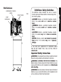
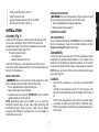
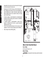
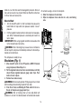
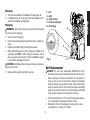
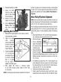
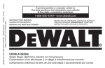
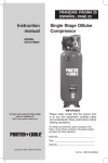
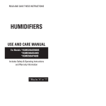
(MAY2013) MAT Industries, LLC, Long Grove, IL 60047 Part No. 200-2925 DXCMV5048055 Copyright © 2007, 2008, 2009, 2010 DEWALT If you have questions or comments, contact us. Pour toute question ou tout commentaire, nous contacter. Si tiene dudas o comentarios, contáctenos. 1-888-895-4549 • www.dewalt.com INSTRUCTION MANUAL GUIDE D'UTILISATION MANUAL DE INSTRUCCIONES INSTRUCTIVO DE OPERACIÓN, CENTROS DE SERVICIO Y PÓLIZA DE GARANTÍA. ADVERNTENCIA: LÉASE ESTE INSTRUCTIVO ANTES DE USAR EL PRODUCTO. DXCMV5048055 Two Stage, Belt Drive, Electric Air Compressors Compresseurs d’air électriques à un étage à entraînement par courroie Compresores eléctricos de aire, de una sola etapa y accionamiento por correa English Air Compressor A A. Pump Air Intake Filter B. Auto(-)/Off(O) Switch C. Air Tank Pressure Gauge D. Regulated Pressure Gauge E. Pressure Regulator F. Air Outlet G. Safety Valve H. Air Tank Drain Valve I. Pump Oil Fill Plug J. Pump Oil Drain Plug K. Check Valve L. Quick Connect (2) I J B G C Pump Specifications 2 Cylinder Two Stage Oil Lubricated Cast iron crankcase, cylinder, and head Weight: 128 lbs. (58 kg.) Oil Capacity: 49 oz. (1449 mL) L/F D E F Specifications MODEL WEIGHT HEIGHT WIDTH AIR TANK CAPACITY APPROX. BLOW OFF PRESSURE FIG. 1 K DXCMV5048055 523 lbs. (237 kg) 76.5” 31.5” 80 gallons (302,8 liters) 200 psi H 2 Hot Surfaces COMPRESSOR CYLINDER & HEAD Definitions: Safety Guidelines FIG. 2 PUMP CRANKCASE IF YOU HAVE ANY QUESTIONS OR COMMENTS ABOUT THIS OR ANY DeWALT TOOL, CALL US TOLL FREE AT: 1-888-895-4549 Important Safety Instructions WARNING: Do not operate this unit until you read this instruction manual for safety, operation and maintenance instructions. WARNING: CALIFORNIA PROPOSITION 65 WARNING: This product contains chemicals known to the State of California to cause cancer, and birth defects or other reproductive harm. Wash hands after handling. WARNING: Some dust contains chemicals known to the State of California to cause cancer, birth defects or other reproductive harm such as asbestos and lead in lead based paint. 3 English OUTLET TUBES The definitions below describe the level of severity for each signal word. Please read the manual and pay attention to these symbols. DANGER: Indicates an imminently hazardous situation which, if not avoided, will result in death or serious injury. WARNING: Indicates a potentially hazardous situation which, if not avoided, could result in death or serious injury. CAUTION: Indicates a potentially hazardous situation which, if not avoided, may result in minor or moderate injury. NOTICE: Indicates a practice not related to personal injury which, if not avoided, may result in property damage. English SAVE THESE INSTRUCTIONS • Unattended operation of this • Always remain in attendance product could result in perwith the product when it is sonal injury or property damoperating. age. To reduce the risk of • Always turn off and disconfire, do no allow the comnect electrical supply from pressor to operator unatunit when not in use. tended DANGER: RISK OF EXPLOSION OR FIRE WHAT CAN HAPPEN HOW TO PREVENT IT • It is normal for electrical con- • Always operate the comprestacts within the motor and sor in a well ventilated area pressure switch to spark. free of combustible materials, gasoline, or solvent vapors. • If electrical sparks from com- • If spraying flammable materipressor come into contact als, locate compressor at with flammable vapors, they least 20' (6.1 m) away from may ignite, causing fire or spray area. An additional explosion. length of air hose may be required. • Store flammable materials in a secure location away from compressor. • Restricting any of the com- • Never place objects against or on top of compressor. pressor ventilation openings will cause serious overheat- • Operate compressor in an open area at least 12” ing and could cause fire. (30.5 cm) away from any wall or obstruction that would restrict the flow of fresh air to the ventilation openings. • Operate compressor in a clean, dry well ventilated area. Do not operate unit in any confined area. Store indoors. DANGER: RISK TO BREATHING (ASPHYXIATION) WHAT CAN HAPPEN HOW TO PREVENT IT • The compressed air directly • Never use air obtained directly from your compressor is not from the compressor to supply safe for breathing. The air air for human consumption. stream may contain carbon The compressor is not monoxide, toxic vapors, equipped with suitable filters or solid particles from the and in-line safety equipment air tank. Breathing these for human consumption. contaminants can cause serious injury or death. • Exposure to chemicals • Work in an area with good in dust created by cross ventilation. Read and power sanding, sawing, follow the safety instructions grinding, drilling and other provided on the label or construction activities may safety data sheets for the be harmful. materials you are spraying. Always use certified safety • Sprayed materials such as equipment: NIOSH/OSHA paint, paint solvents, paint respiratory protection or remover, insecticides, weed properly fitting face mask killers, may contain harmful designed for use with your vapors and poisons. specific application. 4 DANGER: RISK OF BURSTING Air Tank: On February 26, 2002, the U.S. Consumer Product Safety Commission published Release # 02-108 concerning air compressor tank safety: Air compressor receiver tanks do not have an infinite life. Tank life is dependent upon several factors, some of which include operating conditions, ambient conditions, proper installations, field modifications, and the level of maintenance. The exact effect of these factors on air receiver life is difficult to predict. If proper maintenance procedures are not followed, internal corrosion to the inner wall of the air receiver tank can cause the air tank to unexpectedly rupture allowing pressurized air to suddenly and forcefully escape, posing risk of injury to consumers. Your compressor air tank must be removed from service by the end of the year shown on your tank warning label. The following conditions could lead to a weakening of the air tank, and result in a violent air tank explosion: WHAT CAN HAPPEN HOW TO PREVENT IT • Failure to properly drain • Drain air tank daily or after each condensed water from air use. If air tank develops a leak, tank, causing rust and thinning replace it immediately with of the steel air tank. a new air tank or replace the entire compressor. • Modifications or attempted repairs to the air tank. Attachments & Accessories: • Exceeding the pressure rating of air tools, spray guns, air operated accessories, tires and other inflatables can cause them to explode or fly apart, and could result in serious injury. Tires: • Over inflation of tires could result in serious injury and property damage. • Never drill into, weld or make any modifications to the air tank or its attachments. Never attempt to repair a damaged or leaking air tank. Replace with a new air tank. 5 • Follow the equipment manufacturers recommendation and never exceed the maximum allowable pressure rating of attachments. Never use compressor to inflate small low pressure objects such as children’s toys, footballs, basketballs, etc. • Use a tire pressure gauge to check the tires pressure before each use and while inflating tires; see the tire sidewall for the correct tire pressure. NOTE: Air tanks, compressors and similar equipment used to inflate tires can fill small tires very rapidly. Adjust pressure regulator on air supply to no more than the rating of the tire pressure. Add air in small increments and frequently use the tire gauge to prevent over inflation. English • Unauthorized modifications to • The air tank is designed the safety valve, or any other to withstand specific components which control air operating pressures. Never tank pressure. make adjustments or parts substitutions to alter the factory set operating pressures. English DANGER: RISK OF INJURY OR PROPERTY DAMAGE WHEN TRANSPORTING OR STORING WHAT CAN HAPPEN HOW TO PREVENT IT • Oil can leak or spill and could • Always place compressor result in fire or breathing on a protective mat when hazard; serious injury or transporting to protect against death can result. Oil leaks will damage to vehicle from leaks. damage carpet, paint or other Remove compressor from surfaces in vehicles or trailers. vehicle immediately upon arrival at your destination. Always keep compressor level and never lie on its side. WARNING: RISK FROM FLYING OBJECTS WHAT CAN HAPPEN HOW TO PREVENT IT • The compressed air stream • Always wear certified safety can cause soft tissue damage equipment: ANSI Z87.1 eye to exposed skin and can protection (CAN/CSA Z94.3) propel dirt, chips, loose with side shields when using particles and small objects the compressor. at high speed, resulting in • Never point any nozzle or property damage or personal sprayer toward any part of injury. the body or at other people or animals. • Always turn the compressor off and bleed pressure from the air hose and air tank before attempting maintenance, attaching tools or accessories. 6 WARNING: RISK OF HOT SURFACES WHAT CAN HAPPEN HOW TO PREVENT IT • Touching exposed metal such • Never touch any exposed as the compressor head or metal parts on compressor outlet tubes, can result in during or immediately after serious burns. operation. Compressor will remain hot for several minutes after operation • Do not reach around protective shrouds or attempt maintenance until unit has been allowed to cool. • Electrical Grounding: Failure to provide adequate grounding to this product could result in serious injury or death from electrocution. Refer to Grounding Instructions paragraph in the Installation section. WARNING: RISK OF ELECTRICAL SHOCK WHAT CAN HAPPEN HOW TO PREVENT IT • Your compressor is powered • Never operate the compresby electricity. Like any other sor outdoors when it is rainelectrically powered device, ing or in wet conditions. if it is not used properly it • Never operate compresmay cause electric shock. sor with protective covers removed or damaged. 7 • Any electrical wiring or repairs required on this product should be performed by authorized service center personnel in accordance with national and local electrical codes. • Make certain that the electrical circuit to which the compressor is connected provides proper electrical grounding, correct voltage and adequate fuse protection. English • Repairs attempted by unqualified personnel can result in serious injury or death by electrocution. English WARNING: RISK FROM MOVING PARTS WHAT CAN HAPPEN HOW TO PREVENT IT • Moving parts such as the • Never operate the compressor pulley, flywheel, and belt can with guards or covers which are cause serious injury if they damaged or removed. come into contact with you or • Keep your hair, clothing and your clothing. gloves away from moving parts. Loose clothes, jewelry or long hair can be caught in moving parts. • Air vents may cover moving parts and should be avoided as well. • Attempting to operate • Any repairs required on this compressor with damaged or product should be performed missing parts or attempting by a DeWALT factory service to repair compressor with center or a DeWALT authorized protective shrouds removed service center. can expose you to moving parts and can result in serious injury. WARNING: RISK OF UNSAFE OPERATION WHAT CAN HAPPEN HOW TO PREVENT IT • Unsafe operation of your air • Review and understand all compressor could lead to seri instructions and warnings in ous injury or death to you or this manual. others. • Become familiar with the oper ation and controls of the air compressor. • Keep operating area clear of all persons, pets, and obstacles. • Keep children away from the air compressor at all times. • Do not operate the product when fatigued or under the influence of alcohol or drugs. Stay alert at all times. • Never defeat the safety features of this product. • Equip area of operation with a fire extinguisher. • Do not operate machine with missing, broken, or unautho rized parts. • Never stand on the compressor. 8 Know Your Air Compressor WARNING: RISK OF INJURY FROM LIFTING WHAT CAN HAPPEN HOW TO PREVENT IT • Serious injury can result from • The compressor is too heavy attempting to lift too heavy an to be lifted by one person. object. Obtain assistance from others before lifting. FEATURES AUTO (-) / OFF (O) SWITCH Place this switch (B) in the AUTO (-) position to provide automatic power to the pressure switch and OFF(O) to remove power at the end of each use. NOTE: ALWAYS ensure the switch (B) is in the OFF (O) position before removing or replacing B pressure switch cover. PRESSURE SWITCH CAUTION: RISK FROM NOISE WHAT CAN HAPPEN HOW TO PREVENT IT • Under some conditions and • Always wear certified safety duration of use, noise from equipment: ANSI S12.6 this product may contribute to (S3.19) hearing protection. hearing loss. The pressure switch (B) automatically starts the motor when the air tank pressure drops below the factory set cut-in pressure. It stops the motor when the air tank pressure reaches the factory set cut-out pressure. SAFETY VALVE This valve (G) is designed to prevent system G failures by relieving pressure from the system when the compressed air reaches a predeter mined level. The valve is preset by the manu facturer and must not be removed or modified in any way. SAVE THESE INSTRUCTIONS FOR FUTURE USE CHECK VALVE When the air compressor is operating, the check valve (K) is open, allowing compressed air to enter the air tank. When the air compressor K 9 English READ THIS OWNER’S MANUAL AND SAFETY RULES BEFORE OPERATING YOUR UNIT. Compare the illustrations with your unit to familiarize yourself with the location of various controls and adjustments. Save this manual for future reference. To Adjust Regulator: 1.Pull regulator knob (E) out. 2.Turn knob clockwise to increase regulated pressure and counter-clockwise to decrease regulated pressure. 3.When desired pressure is shown on the regulated pressure gauge push knob in to lock. English reaches cut-out pressure, the check valve closes, allowing air pressure to remain inside the air tank. AIR INTAKE FILTER The filter (A) is designed to clean air entering the pump. To ensure the pump continually receives a clean, cool, and dry air supply the filter must always be clean and the filter intake must be free from obstructions. AIR TANK DRAIN VALVE The drain valve (H) is located at the base of the air tank and is used to drain condensation at the end of each use. See Draining Air Tank under Maintenance. A WARNING: Risk of Bursting. Too much air pressure causes a hazardous risk of bursting. Check the manufacturer’s maximum pressure rating for air tools and accessories. The regulator outlet pressure must never exceed the maximum pressure rating. GLOBE VALVE/AIR DISCHARGE VALVE: (sold separately, not shown) Opens and closes air distribution from compressor. See Air Distribution System paragraph under Installation. H REGULATED PRESSURE GAUGE The regulated pressure gauge (D) indicates the air pressure available at the outlet side of the regulator. This pressure is controlled by the regulator and is always less or equal to the air tank pressure. TANK PRESSURE GAUGE The tank pressure gauge (C) indicates the reserve air pressure in the tank. REGULATOR (sold separately, not shown): An air pressure regulator or a separate air transformer which combines the functions of air regulation and/or moisture and dirt removal is recommended for most applications. See Air Distribution System paragraph under Installation. G C E D AIR COMPRESSOR PUMP The pump compresses air into the air tank. Working air is not available until the compressor has raised the air tank pressure above that required at the air outlet. L UNIVERSAL QUICK CONNECT BODY The universal quick connect body (L) accepts the three most popular styles of quick connect plugs: Industrial, automotive, and ARO. One hand push-to-connect operation makes connections simple and easy. MOTOR OVERLOAD PROTECTOR The motor has a thermal overload protector. If the motor overheats for any reason, the overload protector will shut off the motor. The motor must be allowed to cool down before restarting. To restart: REGULATOR The regulator knob (E) controls the air pressure coming from the air tank. 10 M Set the Auto/Off switch to OFF (O). Allow the motor to cool. Depress the red reset button (M) on the motor. Set the Auto/Off switch to AUTO (-). DISCONNECTING HOSES WARNING: Risk of unsafe operation. Firmly grasp hose in hand when installing or disconnecting to prevent hose whip. 1.Ensure regulated pressure gauge reads 0 psi. 2.Remove hose from air outlet (F). INSTALLATION Assembly (Fig. 1) Lubrication and Oil AIR COMPRESSOR The air compressor pump was filled WITH oil at the manufacturer. Check air compressor pump oil level before operating unit. See Compressor Pump Oil under Maintenance. Unpack the air compressor. Inspect the unit for damage. If the unit has been damaged in transit, contact the carrier and complete a damage claim. Do this immediately because there are time limitations to damage claims. The carton should contain: • air compressor • operator and parts manuals Check the compressor’s serial label to ensure that you have received the model ordered, and that it has the required pressure rating for its intended use. INSTALLING HOSES WARNING: Risk of unsafe operation. Firmly grasp hose in hand when installing or disconnecting to prevent hose whip. 1.Ensure regulated pressure gauge reads 0 psi. 2.Apply sealant tape to hose threads. 3.Assemble hose to air outlet (F). IMPORTANT: Do not assemble splitters directly to the air outlet (F). NOTE: Assembling quick connect bodies (L) to air outlet (F) and quick connect plugs to hose ends make connecting and disconnecting hoses simple and easy. Quick connect bodies and plugs are available for purchase from your local dealer or authorized service center. Compatibility Air tools and accessories that are run off the compressor must be compatible with petroleum based products. If you suspect that a material is not compatible with petroleum products, an air line filter for removal of moisture and oil vapor in compressed air is required. NOTE: Always use an air line filter to remove moisture and oil vapor when spraying paint. Location • • • 11 Locate the air compressor in a clean, dry, and well ventilated area. Located the air compressor at least 12” (30.5 cm) away from the wall or other obstructions that will interfere with the flow of air. Locate the air compressor as close to the main power supply as possible to avoid using long lengths of electrical wiring. NOTE: Long lengths of electrical wiring could cause power loss to the motor. English 1. 2. 3. 4. English • The air filter must be kept clear of obstructions which could reduce air flow to the air compressor. 2. Mark the surface 3/8" Lag using the holes in Vibration Screw pad (not supplied) the air compressor (not feet as a template. supplied) 3. Drill holes in the surface for the concrete anchors. Install concrete Surface Line Shim Under anchors. Vibration pad 4.Line-up holes in (not supplied) Concrete Anchor (not supplied) surface with holes in air compressor feet. 5. Place the vibration pads (not supplied) between the floor and air compressor feet, see figure. If needed use shims to level the unit. 6. Place the 3/8” lag screws through the air compressor feet, vibration pads and into the anchors. 7. Torque 3/8” lag screws to 7-10 ft.-lbs (9.5-13.5 Nm). HUMID AREAS In frequently humid areas, moisture may form in the pump and produce sludge in the oil, causing running parts to wear out prematurely. Excessive moisture is especially likely to occur if the unit is located in an unheated area that is subject to large temperature changes. Two signs of excessive humidity are external condensation on the pump when it cools down and a “milky” appearance in compressor oil. You may be able to prevent moisture from forming in the pump by increasing ventilation or operating for longer intervals. NOISE CONSIDERATIONS Consult local officials for information regarding acceptable noise levels in your area. To reduce excessive noise, use vibration mounts or silencers, relocate the unit or construct total enclosures or baffle walls. Contact a DeWALT service center or call 1-888-895-4549 for assistance. Wiring Instructions Anchoring of the Air Compressor WARNING: Improper electrical installation of this product may void its warranty and your fire insurance. Have circuit wiring performed by qualified personnel such as a licensed electrician who is familiar with the current national electrical code and any prevailing local electrical codes. WARNING: Risk of bursting. Excessive vibration can weaken the air tank and cause an explosion. The compressor must be properly mounted. The air compressor MUST be bolted to a level, solid concrete surface. Use 3/8” lag screws, vibration pads and concrete anchors. If help is needed anchoring the air compressor consult a licensed contractor. 1. Place the air compressor on a level, solid concrete surface. Make sure the concrete is in good condition with no cracks or damage. WARNING: Risk of electrical shock. Improper electrical grounding can result in electrical shock. The wiring should be done by a qualified electrician. A qualified electrician needs to knows the following before wiring: 1. The amperage rating of the electrical box should be adequate. 12 If any of the above conditions cannot be met, or if operation of the compressor repeatedly causes interruption of the power, it may be necessary to operate it from a 20 amp circuit. It is not necessary to change the cord set. Main power disconnect switch Install a main power disconnect switch in the line from the panel to the compressor. The main power disconnect switch must be located near the compressor, for ease of use and safety. When turned OFF, the main power disconnect switch shuts off all power to the compressor. When it is turned ON, the compressor will start and stop automatically, controlled by the pressure switch. WARNING: Risk of electrical shock. Electrical wiring must be located away from hot surfaces such as manifold assembly, compressor outlet tubes, heads, or cylinders. Air Distribution System Grounding Instructions WARNING: Risk of bursting. Plastic or PVC pipe is not designed for use with compressed air. Regardless of its indicated pressure rating, plastic pipe can burst from air pressure. Use only metal pipe for air distribution lines. This product should be connected to a metallic, permanent wiring system, of and equipment-grounding terminal or lead on the product. Voltage and Circuit Protection INSTALLING AND DISCONNECTING HOSES WARNING: Risk of unsafe operation. Firmly grasp hose in hand when installing or disconnecting to prevent hose whip. Ensure regulated pressure gauge reads 0 psi. Refer to the Voltage and Minimum Branch Circuit Requirements under Specifications. CAUTION: Certain air compressors can be operated on a 15 amp circuit if the following conditions are met. • Voltage supply to circuit must comply with the National Electrical Code. • Circuit is not used to supply any other electrical needs. • Extension cords comply with specifications. • Circuit is equipped with a 15 amp circuit breaker or 15 amp time delay fuse. NOTE: If compressor is connected to a circuit protected by fuses, use only time delay fuses. Time delay fuses should be marked “D” in Canada and “T” in the U.S. The next figure represents a typical air distribution system. The following are tips to remember when setting up the air compressor’s air distribution system. NOTE: Compressed air from oil lube air compressors will contain water condensation and oil mist. Several drains, traps and filters will be needed to supply air without water (including aerosols) or oil to spray equipment, air tools and accessories requiring filtered air. Always read the instructions for the air tools and accessories being used. 13 English Refer to the Specifications, in the parts manual, for this information. 2. The supply line should have the same electrical characteristics (voltage, cycle, phase) as the motor. Refer to the motor nameplate, on side of motor, for this information. NOTE: The wiring used must be rated for the motor nameplate voltage, plus or minus 10%. Refer to local codes for recommended wire sizes, correct wire size, and maximum wire run; undersize wire causes high amp draw and overheating to the motor. English • • • • • • • Use pipe that is the same size as the air tank outlet. Piping that is too small will restrict the flow of air. If piping is over 100’ (30.5 m) long, use the next larger size. Bury underground lines below the frost line and avoid pockets where condensation can gather and freeze. Apply pressure before underground lines are covered to make sure all pipe joints are free of leaks. A flexible coupling is recommended to be installed between the globe valve/air discharge outlet and main air distribution line to allow for vibration. A separate regulator is recommended to control the air pressure. Air pressure from the tank is usually too high for individual air driven tools. DO NOT install lubricators between the tank and any spray equipment, air tool or accessory requiring oil-free filtered air. Drain all traps, filters and dirt legs daily. FEEDER LINES SLOPE WITH AIR FLOW A R FLOW MA N DISTRIBUTION AIR L NES Slope pipe in di rection of air flo w Water condensate flows along bottom of pipe to drain legs prevent ng t f rom enter ng feeder lines 01 M CRON FI LTER AIR FLOW DRAIN LEGS AIR USAGE L NES DRAIN VALVES 5 MICRON FI LTER FI LTER / MOISTURE TRAP DIR T LEGS SPR AY GUN REGUL ATOR LUBRIC ATOR DRAIN VALVES REGUL ATOR BALL FI LTER AIR TOOL FI LTER / MOISTURE TRAP DRAIN VALVE FOR BEST PERFORMANCE the d stance between the comp ressor and the moistu re trap should be as long as possib e FLEXIBLE COUPL NG TYPICAL COMPRESSED AIR DISTRIBUTION SYSTEM AIR COMPRESSOR GLOBE VALVE / AIR DISCHARGE VALVE DRAIN VALVE RISK OF BURSTING A LWAYS USE ME TAL PIPING AND FITT NGS How to Use Your Unit (Fig 3) How to Stop: Set the Auto/Off switch to “Off”. Before Starting WARNING: Do not operate this unit until you read this instruction 14 manual for safety, operation and maintenance instructions. Break-in Procedure NOTICE: Risk of property damage. Serious damage may result if the following break-in instructions are not closely followed. The compressor is now ready for use. This procedure is required before the air compressor is put into service and when the check valve or a complete compressor pump has been replaced. 1. Make sure the Auto/Off switch is in the “Off” position. 2. Check oil level in pump. See Oil paragraph in the Maintenance section for instructions. 3. Recheck all wiring. Make sure wires are secure at all terminals connections. Make sure all contacts move freely and are not obstructed. 4. Open the drain valve (counterclockwise) fully to permit air to escape and prevent air pressure build up in the air tank during the break-in period. 5. Move the Auto/Off switch to “Auto” position. The compressor will start. 6. Run the compressor for 30 minutes. Make sure the drain valve and all air lines are open so there is only a minimal air pressure build-up in tank. NOTE: After about 30 minutes, If the unit does not operate properly, SHUT DOWN IMMEDIATELY, and contact Product Service. 7. Check all air line fittings and connections/piping for air leaks by applying a soap solution. Correct if necessary. NOTE: Minor leaks can cause the air compressor to overwork, resulting in premature breakdown or inadequate performance. 8. Check for excessive vibration. Readjust or shim air compressor feet, if necessary. Before Each Start-Up 1. 2. 3. 4. Place Auto/Off switch to “Off”. Close the drain valve. Visually inspect air lines and fittings for leaks. Check safety valve. See To Check Safety Valve under Maintenance. 5. Pull the regulator knob out and turn counterclockwise to set the outlet pressure to zero. 6. Attach hose and accessories. WARNING: Risk of unsafe operation. Firmly grasp air hose in hand when installing or disconnecting to prevent hose whip. WARNING: Risk of unsafe operation. Do not use damaged or worn accessories. NOTE: A regulator MUST be installed when using accessories rated at less than 135 psi. NOTE: The hose or accessory will require a quick connect plug if the air outlet is equipped with a quick connect socket. WARNING: Risk of bursting. Too much air pressure causes a hazardous risk of bursting. Check the manufacturer’s maximum pressure rating for air tools and accessories. The regulator outlet pressure must never exceed the maximum pressure rating. CAUTION: Risk of unsafe operation. Compressed air from the unit may contain water condensation and oil mist. Do not spray unfil 15 English 9. After 30 minutes, turn the Auto/Off switch to the “Off” position. 10. Close the drain valve. 11. Turn the Auto/Off switch to the “Auto” position. The air receiver will fill to “cut-out” pressure and the motor will stop. English tered air at an item that could be damaged by moisture. Some air tools and accessories may require filtered air. Read the instructions for the air tools and accessories. the air tank causing a risk of air tank rupture. 5. Allow the compressor to cool down. 6. Wipe air compressor clean and store in a safe, non-freezing area. How to Start 1. Turn the Auto/Off switch to “Auto” and allow tank pressure to build. Motor will stop when tank pressure reaches “cut-out” pressure. 2. Pull the regulator knob out and turn clockwise to increase pressure. When the desired pressure is reached push knob in to lock in place. IMPORTANT: When using regulator and other accessories refer to the manufacturers instructions. FIG. 3 WARNING: Risk of bursting. If any unusual noise or vibration is noticed, stop the compressor immediately and have it checked by a trained service technician. OFF AUTO The compressor is ready for use. Shut-down (Fig. 1) 1. Move Auto/Off switch to the OFF position. NOTE: If finished using compressor, follow Steps 2 - 6. 2. Pull the regulator knob out and turn counterclockwise until fully closed. Ensure regulated pressure gauge reads 0 psi. Push knob in to lock in place. 3. Remove hose and accessory. WARNING: Risk of unsafe operation. Firmly grasp air hose in hand when installing or disconnecting to prevent hose whip. 4. Drain the air tank, see Draining Air Tank under Maintenance. Ensure air tank pressure gauge reads 0 psi. WARNING: Risk of bursting. Drain air tank daily. Water will condense in air tank. If not drained, water will corrode and weaken OPEN CLOSE 16 X Inspect air filter Drain air tank 1 year or 200 Hours See tank warning label Monthly Daily Check safety valve cally when power is on. When performing maintenance, you may be exposed to voltage sources, compressed air, or moving parts. Personal injuries can occur. Before performing any maintenance or repair, disconnect power source from the compressor and bleed off all air pressure. To ensure efficient operation and longer life of the air compressor outfit, a routine maintenance schedule should be prepared and followed. The following routine maintenance schedule is geared to an outfit in a normal working environment operating on a daily basis. If necessary, the schedule should be modified to suit the conditions under which your compressor is used. The modifications will depend upon the hours of operation and the working environment. Compressor outfits in an extremely dirty and/or hostile environment will require a greater frequency of all maintenance checks. NOTE: See Operation section for the location of controls. X+ X Check pump oil level X Change pump oil X **+ Oil leak inspection X Inspect drive belt X Check drive belt tension X X Check pulley/flywheel alignment Check for unusual noise/vibration X Check for air leaks X* Clean compressor exterior X Remove tank from service X++ * To check for air leaks apply a solution of soapy water around joints. While compressor is pumping to pressure and after pressure cuts out, look for air bubbles to form. ** The pump oil must be changed after the first 20 hours or operation. Thereafter, when using synthetic blend non-detergent air compressor oil, change oil every 200 hours of operation or once a year, whichever comes first. + Perform more frequent in dusty or humid conditions. ++ For more information, call 1-888-895-4549 . WARNING: Checking Safety Valve (Fig. 1) WARNING: Hot surfaces. Risk of burn. Tubes, pump head, and surrounding parts are very hot, do not touch (see the Hot Surfaces identified in Fig. 2). Allow compressor to cool prior to servicing. WARNING: Risk of bursting. If the safety valve does not work properly, over-pressurization may occur, causing air tank rupture or an explosion. WARNING: Risk from flying objects. Always wear certified safety equipment: ANSI Z87.1 eye protection (CAN/CSA Z94.3) with side shields. Before starting compressor, pull the ring on the safety valve to make sure that the safety valve operates freely. If the valve is stuck or does not operate smoothly, it must be replaced with the same type of valve. Risk of unsafe operation. Unit cycles automati17 English Procedure Weekly MAINTENANCE Maintenance Chart English Checking Air Filter (Fig. 1) condensate contains lubricating oil and/or substances which may be regulated and must be disposed of in accordance with local, state, and federal laws and regulations. 1. Set the Auto/Off switch to “Off”. 2. Pull the regulator knob out and turn counterclockwise to set the outlet pressure to zero. 3. Remove the air tool or accessory. 4. Pull ring on safety valve allowing air to bleed from the tank until tank pressure is approximately 20 psi. Release safety valve ring. 5. Drain water from air tank by opening drain valve (counterclockwise) on bottom of tank. WARNING: Hot surfaces. Risk of burn. Tubes, pump head, and surrounding parts are very hot, do not touch (see the Hot Surfaces identified in Fig. 2). Allow compressor to cool prior to servicing. A dirty air filter will not allow the compressor to operate at full capacity. Keep the air filter clean at all times. 1. Ensure Auto/Off switch (B) is in the OFF Position. 2. Allow unit to cool. N P O 3. Remove the wing nut (N). 4. Remove the outer metal cover (O). 5. Check the filter element (P) if it is dirty or filled with paint, replace it. 6. Place the outer metal cover back over the filter element. 7. Secure with the wing nut. CAUTION: Risk of unsafe operation. Do not operate without air filter. WARNING: Risk of bursting. Water will condense in the air tank. If not drained, water will corrode and weaken the air tank causing a risk of air tank rupture. NOTICE: Risk of property damage. Drain water from air tank may contain oil and rust which can cause stains. 6. After the water has been drained, close the drain valve (clockwise). The air compressor can now be stored. NOTE: If drain valve is plugged, release all air pressure. The valve can then be removed, cleaned, then reinstalled. Draining Air Tank (Fig. 3) WARNING: Risk of unsafe operation. Air tanks contain high pressure air. Keep face and other body parts away from outlet of drain. Use eye protection [ANSI Z87.1 (CAN/CSA Z94.3)] when draining as debris can be kicked up into face. Compressor Pump Oil (Fig. 4) NOTICE: Risk of property damage. Use air compressor oil only. Multi-weight automotive engine oils like 10W30 should not be used in air compressors. They leave carbon deposits on critical components, thus reducing performance and compressor life. WARNING: Risk from noise. Use ear protection (ANSI S12.6 (S3.19) as air flow noise is loud when draining. NOTE: Use synthetic blend non-detergent air compressor oil. NOTE: Crankcase oil capacity is approximately 49 fluid ounces (1449 ml). NOTE: All compressed air systems generate condensation that accumulates in any drain point (e.g., tanks, filter, aftercoolers, dryers). This 18 Checking Changing Q WARNING: Drain tank to release air pressure before removing the oil fill cap or oil drain plug. 1. Remove the oil fill plug (Q). 2. Remove the oil drain plug (R) and drain oil into a suitable container. 3. Replace the oil drain plug (R) and tighten securely 4. Slowly add compressor oil until it reaches the middle of the sight glass (S). NOTE: When filling the crankcase, the oil flows very slowly into the pump. If the oil is added too quickly, it will overflow and appear to be full. S Fig. 4 CAUTION: Overfilling with oil will cause premature compressor failure. Do not overfill. R Belt Replacement WARNING: This unit starts automatically. ALWAYS shut off the main power disconnect, and bleed all pressure from the system before servicing the compressor, and when the compressor is not in use. Do not use the unit with the shrouds or belt guard removed. Serious injury could occur from contact with moving parts. Hot surfaces. Risk of burn. Pump head, and surrounding parts are very hot, do not touch (see the Hot Surfaces identified in Fig. 2). Allow compressor to cool prior to servicing. 5. Replace oil fill plug (Q) and tighten securely. 1. Set the Auto/Off lever to “Off”, shut off the main power disconnect, and relieve all air pressure from the air tank. 2. Remove the front of the beltguard by removing the screws and washers (V) using a Torx T25 bit. 19 English T = Full U = Add R = Oil drain plug S = Oil level sight glass Q = Oil fill plug 1. The oil level should be to the middle of the sight glass (S). 2. If needed remove oil fill plug (Q) and slowly add oil until it reaches the middle of the sight glass. English location, the grooves of the flywheel and pulley must be aligned to within 1/16” (1.6 mm) to prevent excessive belt wear. Verify the alignment by performing the following Motor Pulley/Flywheel Alignment. 3. Mark pump position on saddle. 4.Loosen the motor V mounting screws and slide the motor toward the air compressor. 5. Remove the belt and replace with a new one. 6. See the Adjusting Belt Tension before tightening motor mounting screws. Motor Pulley/Flywheel Alignment NOTE: Once the motor pulley has been moved from its factory set location, the grooves of the flywheel and pulley must be aligned to within 1/16” (1.6 mm) to prevent excessive belt wear. The air compressor flywheel and motor pulley must be in-line (in the same plane) within 1/16” (1.6 mm) to assure belt retention within flywheel belt grooves. To check alignment, perform the following steps: 1. Set the Auto/Off lever to “Off”, shut off the main power disconnect, and relieve all air pressure from the air tank. 2. Remove belt guard. 3. Place a straightedge against the outside of the flywheel and the motor drive pulley. 4. Measure the distance between the edge of the belt and the straightedge at points A1 and A2 in figure. The difference between measurements should be no more than 1/16” (1.6 mm). 5. If the difference is greater than 1/16” (1.6 mm) loosen the set screw holding the motor drive pulley to the shaft and adjust the pulley’s position on the shaft until the A1 and A2 measurements are within 1/16” (1.6 mm) of each other. 6. Tighten the motor drive pulley set screw. 7. Visually inspect the motor drive pulley to verify that it is perpendicular to the drive motor shaft. Points B1 and B2 of Figure Adjusting Belt Tension 1. Slide motor into original position, line the motor up with the mark made earlier on saddle. 2. Tighten two outside Dow motor mounting nwar d Fo rce screws enough to hold the motor in place for checking pulley and flywheel alignment. Deflection 3. The belt should deflect 1/2” (13 mm)at midway between the pulley and the flywheel when a 10 pound (4.6 kg.) weight is applied at the midway point. 3.When proper belt tension is achieved, tighten all four motor mounting screws. Torque to 20-25 ft-lbs (27.1–33.9 Nm). NOTE: Once the engine pulley has been moved from its factory set 20 cally when power is on. When servicing, you may be exposed to voltage sources, compressed air, or moving parts. Before servicing unit unplug or disconnect electrical supply to the air compressor, bleed tank of pressure, and allow the air compressor to cool. To Replace or Clean Check Valve Air Compressor Pump Intake and Exhaust Valves 1. Release all air pressure from air tank. See Draining Air Tank in the Maintenance section. 2. Set the Auto/Off lever to “Off”, shut off the main power disconnect, and relieve all air pressure from the air tank. 3. Using an adjustable wrench loosen outlet tube nut at air tank and pump. Carefully Screwdriver move outlet tube In open away from check position valve. nothing is 4. Using an adjustable visible. wrench loosen presIn closed position sure relief tube nut disc is visible. at air tank. Carefully move pressure relief tube away from check valve. 5. Unscrew the check valve (turn counterclockwise) using a 7/8” open end wrench. NOTE the orientation for reassembly. 6. Using a screwdriver, carefully push the valve disc up and down. NOTE: The valve disc should move freely up and down on a spring which holds the valve disc in the closed position, if not the check valve needs to be cleaned or replaced. 7. Clean or replace the check valve. A solvent, such as paint or varnish remover can be used to clean the check valve. 8. Apply sealant to the check valve threads. Reinstall the check Once a year have a Trained Service Technician check the air compressor pump intake and exhaust valves. Inspect Air Lines and Fittings for Leaks 1. Set the Auto/Off lever to “Off”, shut off the main power disconnect, and relieve all air pressure from the air tank. 2. Apply a soap solution to all air line fittings and connections/ piping. 3. Correct any leaks found. IMPORTANT: Even minor leaks can cause the air compressor to overwork, resulting in premature breakdown or inadequate performance. Air compressor Head Bolts - Torquing The air compressor pump head bolts should be kept properly torqued. Check the torques of the head bolts after the first five hours of operation. Torque to 14-16 ft.‑lbs. (18.9–21.7 Nm). Service and Adjustments ALL MAINTENANCE AND REPAIR OPERATIONS NOT LISTED MUST BE PERFORMED BY TRAINED SERVICE TECHNICIAN. WARNING: Risk of unsafe operation. Unit cycles automati21 English should appear to be equal. If they are not, loosen the setscrew of the motor drive pulley and equalize B1 and B2, using care not to disturb the belt alignment performed in step 2. 8. Retighten the motor drive pulley setscrew. Torque to 145–165 in lbs (16.4–20.3 Nm). 9. Reinstall belt guard. English Limited Warranty valve (turn clockwise). 9. Replace the pressure release tube. Tighten nuts. 10. Replace the outlet tube and tighten nuts. 11. Perform the Break-in Procedure. See Break-in Procedure in the Operation section. DEWALT Industrial Tools are warranted from date of purchase. 2 Year – Limited warranty on oil-lubricated air compressor pumps. 1 Year – Limited warranty on all other air compressor components. This warranty is not transferable to subsequent owners. DEWALT will repair or replace, without charge, at DEWALT’s option, any defects due to faulty materials or workmanship. For further detail of warranty coverage and warranty repair information, call 1-(888)-895-4549 or visit dewalt.com. This warranty does not apply to accessories or damage caused where repairs have been made or attempted by others. This warranty also does not apply to merchandise sold by DEWALT which has been manufactured by and identified as the product of another company, such as gasoline engines. Such manufacturer’s warranty, if any, will apply. ANY INCIDENTAL, INDIRECT OR CONSEQUENTIAL LOSS, DAMAGE OR EXPENSE THAT MAY RESULT FROM ANY DEFECT, FAILURE OR MALFUNCTION OF THE PRODUCT IS NOT COVERED BY THIS WARRANTY. Some states do not allow the exclusion of limitation of incidental or consequential damages, so the above limitation or exclusion may not apply to you. IMPLIED WARRANTIES, INCLUDING THOSE OF MERCHANTABILITY OR FITNESS FOR A PARTICULAR PURPOSE, ARE LIMITED TO ONE YEAR FROM THE DATE OF ORIGINAL PURCHASE. Some states do not allow limitations on how long an implied warranty lasts, so the above limitations may not apply to you. What the Company Will Do: (the company) will cover parts and labor to remedy substantial defects due to materials Additional Service Disassembly or service of the air compressor beyond what is covered in this manual is not recommended. If additional service is required, contact your nearest Authorized Warranty Service Center. Accessories Recommended accessories for use with your tool are available for purchase from your local dealer or authorized service center. If you need assistance in locating any accessory for your tool, please call 1-888-895-4549 or visit our website www.dewalt.com. WARNING: The use of any other accessory not recommended for use with this tool could be hazardous. Use only accessories rated equal to or higher than the rating of the air compressor. Service Information Please have the following information available for all service calls: Model Number ____________ Serial Number ___________ Date and Place of Purchase ____________________________ Repairs To assure product SAFETY and RELIABILITY, repairs, maintenance and adjustment should be performed by a DeWALT factory service center, a DeWALT authorized service center or other qualified service personnel. Always use identical replacement parts. 22 • Labor, service calls, and travel charges, are not covered after the first year of ownership on stationary compressors (compressors without handles, or wheels). Repairs requiring overtime, weekend rates, or any other charges beyond the standard shop labor rate are not covered. • Time required for orientation training for the service center to gain access to the product, or additional time due to inadequate egress. • Damage caused by incorrect voltage, improperly wired, or failure to have a certified licensed electrician install the compressor, will render this warranty null and void. • Damage caused from inadequate filter maintenance. • Pump wear or valve damage caused by using oil not specified. • Pump wear or damage caused by any oil contamination. • Pump wear or valve damage caused by failure to follow proper maintenance guidelines. • Operation below proper oil level or operation without oil. • Gas Engines, if product is equipped with a gas engine, see engine manual for specific engine manufacturer’s warranty coverage. Parts purchased separately: The warranty for parts purchased separately such as: pumps, motors, etc., are as follows: From Date of Purchase • All single & two stage pumps 1 year • Electric motors 90 days • Universal motor/pump 30 days 23 English and workmanship during the first year of ownership, with the exceptions noted below. Parts used in repair of whole goods or accessories are warranted for the balance of the original warranty period. What is not covered Under This Warranty? Failures by the original retail purchaser to install, maintain, and operate said equipment in accordance with standard industry practices. Modifications to the product, or tampering with components, or failure to comply with the specific recommendations of the Company set forth in the owner’s manual, will render this warranty null and void. The Company shall not be liable for any repairs, replacements, or adjustments to the equipment, or any costs for labor performed by the purchaser without the Company’s prior written approval. The effects of corrosion, erosion, surrounding environmental conditions, cosmetic defects, and routine maintenance items, are specifically excluded from this warranty. Routine maintenance items such as: oil, lubricants, and air filters, as well as changing oil, air filters, belt tensioning, etc… fall under the owner’s responsibility. Additional exclusions include: freight damage, failures resulting from neglect, accident, or abuse, induction motors when operated from a generator, oil leaks, air leaks, oil consumption, leaky fittings, hoses, petcocks, bleeder tubes, and transfer tubes. • The following components are considered normal wear items and are not covered after the first year of ownership: Belts, sheaves, flywheels, check valves, pressure switches, air unloaders, throttle controls, electric motors, brushes, regulators, o-rings, pressure gauges, tubing, piping, fittings, fasteners, wheels, quick couplers, gaskets, seals, air filter housings, piston rings, connecting rods, and piston seals. English • All other parts 30 days • No return authorization will be issued for electrical components once items are installed. How do You Get Service? In order to be eligible for service under this warranty you must be the original retail purchaser, and provide proof of purchase from one of the Company’s dealers, distributors, or retail outlet stores. Portable compressors or components must be delivered, or shipped, to the nearest Authorized Service Center. All associated freight costs and travel charges must be borne by the consumer. Please call our toll free number 1-888-895-4549 for assistance. FREE WARNING LABEL REPLACEMENT: If your warning labels become illegible or are missing, call 1-888-895-4549 for a free replacement. THIS WARRANTY GIVES YOU SPECIFIC LEGAL RIGHTS, AND YOU MAY ALSO HAVE OTHER RIGHTS WHICH VARY FROM STATE TO STATE. THE COMPANY MAKES NO OTHER WARRANTY OR REPRESENTATION OF ANY KIND WHATSOEVER, EXPRESSED OR IMPLIED, EXCEPT THAT OF TITLE. ALL IMPLIED WARRANTIES, INCLUDING ANY WARRANTY OF MERCHANTABILITY AND FITNESS FOR PARTICULAR PURPOSE ARE HEREBY DISCLAIMED. LIABILITY FOR CONSEQUENTIAL AND INCIDENTAL DAMAGES UNDER ANY AND ALL WARRANTIES, OTHER CONTRACTS, NEGLEGENCE, OR OTHER TORTS IS EXCLUDED TO THE EXTENT EXCLUSION IS PERMITTED BY LAW. 24 Troubleshooting Guide 25 English This section provides a list of the more frequently encountered malfunctions, their causes and corrective actions. The operator or maintenance personnel can perform some corrective actions, and others may require the assistance of a qualified DeWALT technician or your dealer. Air leaks ..................................................................................................................................... 1 Air leaks in air tank or at air tank welds..................................................................................... 2 Air leaks between head and valve plate..................................................................................... 3 Air leaks from safety valve.......................................................................................................... 4 Compressor is not supplying enough air to operate accessories............................................. 1, 5, 6, 7, 9, 10 Restricted air intake.................................................................................................................... 9 Oil in discharge air...................................................................................................................... 9, 19, 31 Knocking Noise.......................................................................................................................... 4, 10, 11, 12, 13, 14 Excessive belt wear.................................................................................................................... 10, 11, 14, 15 Squealing sound......................................................................................................................... 10 Moisture in pump crankcase...................................................................................................... 1, 3, 8, 17, 18, 19, 20, 21, 22 Excessive current draw.............................................................................................................. 14, 26, 27 Compressor won’t start in cold temperatures........................................................................... 17, 34, 35 Pressure reading on the regulated pressure gauge drops when and accessory is used.......... 23 Regulator knob has continuous air leak..................................................................................... 24 Regulator will not shut off air outlet........................................................................................... 24 Air tank pressure will not build................................................................................................... 25 Compressor stalls....................................................................................................................... 28, 29, 30 Overheating................................................................................................................................ 27, 32, 33 English Troubleshooting Codes CODE POSSIBLE CAUSE POSSIBLE SOLUTION 1 Fittings are not tight Tighten fittings where air can be heard escaping. Check fittings with soapy water solution. DO NOT OVERTIGHTEN. 2 Defective air tank Air tank must be replaced. Do not repair the leak. WARNING: Risk of bursting. Do not drill into, weld or otherwise modify air tank or it will weaken. The air tank can rupture or explode. 3 Leaking seals Contact a DeWALT factory service center or a DeWALT authorized service center. 4 Defective safety valve Operate safety valve manually by pulling on ring. If valve still leaks, it must be replaced. 5 Prolonged excessive use of air Decrease amount of air usage. 6 Compressor is not large enough for accessory Check the accessory air requirement. If it is higher than the SCFM or pressure supplied by your air compressor, a larger compressor is needed to operate accessory. 7 Hole in air hose Check and replace air hose, if required. 8 Unit operating in damp or humid conditions Move unit to a dry well ventilated area. 9 Restricted air intake filter Clean or replace air intake filter. 10 Loose belt Check belt tension, see Adjusting Belt Tension under Maintenance. 11 Loose pulley Tighten pulley set screw, torque to 85-90 in.-lbs. (9.6–10.2 Nm). 12 Loose flywheel Tighten flywheel (20.0–24.4 Nm). 26 screw, torque to 14–18 ft.-lbs. CODE POSSIBLE SOLUTION 13 Carbon build-up in pump Contact a DeWALT factory service center or a DeWALT authorized service center. 14 Belt to tight Check belt tension, see Adjusting Belt Tension under Maintenance. 15 Pulley misalignment See Motor Pulley/Flywheel Alignment under Maintenance. 16 Pump oil is low Add synthetic blend, non-detergent air compressor oil to pump. See Compressor Pump Oil under Maintenance. 17 Detergent type oil being used in pump Drain oil and refill pump with synthetic blend non-detergent air compressor oil. 18 Extremely light duty cycles Run unit for longer duty cycles. It is recommended to run at high throttle 50-75% of the run time and idle for 25% of the run time. 19 Piston rings damaged or worn Contact a DeWALT factory service center or a DeWALT authorized service center. 20 Cylinder or piston damaged or worn Contact a DeWALT factory service center or a DeWALT authorized service center. 21 Compressor cylinder finish worn Contact a DeWALT factory service center or a DeWALT authorized service center. 22 Water in pump oil Drain oil and refill pump with synthetic blend non-detergent air compressor oil. 23 Regulator is not adjusted correctly for accessory It is normal for some pressure drop to occur when and accesbeing used. sory is used, adjust the regulator as instructed in Regulator under Features if pressure drop is excessive. NOTE: Adjust the regulated pressure under flow conditions while the accessory is being used. 27 English POSSIBLE CAUSE English CODE POSSIBLE CAUSE POSSIBLE SOLUTION 24 Damaged regulator Replace 25 Regulator open Roate the regulator knob counter-clockwise to its built-in stop and push knob in to lock in place. 26 Low voltage/motor overload Check that power supply is adequate and that compressor is on a dedicated circuit. If using extension cord, try using without. If compressor is connected to a circut protected by a fuse, use dual element time delay fuses (Buss Fusetron type “T” only). 27 Restricted air passages Inspect and replace transfer tubes or check valve, as required. 28 Low voltage motor Furnish adequate powder. 29 Bad check valve Replace check valve. 30 Seized pump Contact a DeWALT factory service center or a DeWALT authorized service center. 31 Oil level too high Reduce to proper level. See Compressor Pump Oil under Maintenance. 32 Poor ventilation Relocate compressor to an area with cool, dry, well circulated air, at least 12 in. from nearest wall. 33 Dirty cooling surfaces Clean all cooling surfaces thoroughly. 34 Too much back pressure in tank. Open drain valve when starting motor. 35 Compressor too cold Move compressor to a warmer location. 28 GLOSSARY NOTES English CFM: Cubic feet per minute. SCFM: Standard cubic feet per minute; a unit of measure of air delivery. PSI: Pounds per square inch; a unit of measure of pressure. Cut-in pressure: Factory set low pressure point that starts the compressor to repressurize the tank to a higher pressure. Cut-out pressure: Factory set high pressure point that stops the compressor from increasing the pressure in the tank above a certain level. Well-ventilated: A means of providing fresh air in exchange for dangerous exhaust or vapors. Dedicated circuit: An electrical circuit reserved for the exclusive use of the air compressor. ASME: American Society of Mechanical Engineers. Indicates that the components are manufactured, tested and inspected to the specifications set by ASME. CSA: Canadian Standards Association Indicates that the products that have this marking have been manufactured, tested and inspected to standards that are set by CSA. Canadian Standards Association (USA): Indicates that the products that have this marking have been manufactured, tested and inspected to standards that are set by CSA. These products also conform to U.L. standard 1450. California Code: Unit may comply with California Code 462 (l) (2)/ (M) (2). Specification/model label is on the side of the air tank on units that comply with California Code. 29 For product, service or warranty information contact us at: Para el producto, servicio o información sobre la garantía contacte con nosotros en: Pour les produits, services ou informations sur la garantie nous contracter à: 1-888-895-4549 www. .com MAT Industries, LLC, Long Grove, IL 60047 Under license from DEWALT Industrial Tool Co. Bojo licencia de DEWALT Industrial Tool Co. Sous licence de DEWALT Industrial Tool Co. The following are trademarks for one or more DEWALT power tools: thee yellow and black color scheme; the “D” shaped air intake grill; the array of pyramids on the handgrip; the kit box configuration; and the array of lozenge shape humps on the surface of the tool. Las siguientes son características únicas de una o más herramientas eléctricas y accesorios de DEWALT: El esquema de color amarillo y negro, la parrilla de admisión de aire en “D”, la formación de pirámides en el mango, la configuración de la caja de herramientas y la formación de rombos en la superficie de la herramienta. Vous trouverez ci-après les marques de commerce d’un ou plusieurs outils électriques et accessoires DEWALT. L’agencement de couleurs jaune et noir, la grille d’admission d’air en forme de “D”, la distribution de pyramides sur la poignée, le format du boîter et la matrice complexe de bosses en forme de losanges sur la surface de l’outil.