1
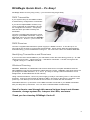
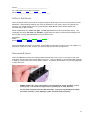
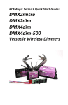
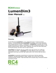
RC4Magic
Series 2 R3
Wireless DMX and
Wireless Dimming System
DMXioR3
Data Transceiver
DMX2dimR3
2-Channel Receiver/Dimmer
DMX4dimR3
4-Channel Receiver/Dimmer
DMX4dim-500R3
fanless
4-Channel High Power
Receiver/Dimmer
System User Manual
All RC4Magic devices are warranted for life.
If it stops working, and you have not misused or abused it, we fix.
For free. Forever. Details on page 30.
1
RC4Magic Series 2 R3
User Manual –
Table of Contents
Disclaimers ............................................................................................................... 4
Not for Use Where Human Safety May Be At Risk .................................................. 4
Not for Control of Pyrotechnical Devices ................................................................. 4
Product Safety ........................................................................................................ 4
Statements of RF Conformity .................................................................................. 4
United States (FCC) ................................................................................................ 4
Canada (IC) ............................................................................................................ 4
Japan ...................................................................................................................... 4
Europe (ETSI) ......................................................................................................... 4
Other Countries and Jurisdictions ........................................................................... 4
RC4Magic Quick Start – It’s Easy! ........................................................................... 5
DMX Transmitter ..................................................................................................... 5
DMX Receiver ......................................................................................................... 5
Identifying Transmitters and Receivers ................................................................... 5
Wireless Dimming ................................................................................................... 5
RC4Magic – An Overview ......................................................................................... 6
DMX Cable Replacement / DMX Distribution .......................................................... 6
Wireless Low-Voltage Dimming............................................................................... 6
System ID Numbers: Ultimate Data Security ........................................................... 6
Power-Up Sequence and Radio Channel Assignments ........................................... 7
Advanced Settings .................................................................................................. 8
DMXio R3 User Interface .......................................................................................... 8
LEDs at Power Up .................................................................................................. 8
LEDs in Running Mode ........................................................................................... 9
LEDs in Edit Mode ................................................................................................ 11
Recessed Buttons ................................................................................................. 11
Buttons at Power Up ............................................................................................. 12
Buttons in Running Mode ...................................................................................... 12
DMXioR3 Transmitter Setup .................................................................................. 13
DMXio Receiver Setup............................................................................................ 14
DMX2dimR3 Receiver-Dimmer Setup .................................................................... 15
DMX4dim Receiver-Dimmer Setup ........................................................................ 18
DMX4dim-500R3 fanless High Power Receiver-Dimmer Setup ........................... 21
2
Dimmer Resolution and Curves............................................................................. 22
Dimmer Resolution ............................................................................................... 22
Dimmer Curves ..................................................................................................... 22
Optimizing Radio Performance.............................................................................. 23
How do I… ............................................................................................................... 24
Troubleshooting and Frequently Asked Questions ............................................. 24
General ................................................................................................................. 24
Mounting and Positioning ...................................................................................... 26
Dimmer Problems ................................................................................................. 26
RC4Magic Series 2 Specifications ......................................................................... 28
RC4Magic RF Technology .................................................................................... 28
RC4Magic DMX Protocol Compliance ................................................................... 28
DMXioR3 .............................................................................................................. 28
DMX2dimR3 Receiver-Dimmer ............................................................................. 28
DMX4dimR3 Receiver-Dimmer ............................................................................. 29
DMX4dim-500R3 fanless Receiver-Dimmer ......................................................... 29
Warranty Policy ...................................................................................................... 30
Seven-Day Easy Return ........................................................................................ 30
Thirty-Day Replacement or Fast-Turn Service Guarantee ....... Error! Bookmark not
defined.
One Year Parts and Labor General Guarantee ........ Error! Bookmark not defined.
Out of Warranty Service Policy................................. Error! Bookmark not defined.
Disclaimers We Must Make ................................................................................... 30
How to Reach RC4 Wireless .................................................................................. 31
Physical Address .................................................................................................. 31
Telephone / Fax .................................................................................................... 31
Internet ................................................................................................................. 31
3
Disclaimers
WIRING AND INSTALLATION OF BATTERIES, DIMMERS, AND LOADS MUST BE IN ACCORDANCE
WITH APPLICABLE LOCAL AND NATIONAL ELECTRICAL CODES.
RC4 Wireless devices and equipment are operated at the user’s own risk and RC4 Wireless accepts no
liability, either direct or consequential, as a result of using this equipment.
Not for Use Where Human Safety May Be At Risk
RC4 Wireless accepts no liability for direct, indirect, or consequential damages resulting from the
use of any RC4 Wireless product or group of products. RC4 Wireless does not guarantee the
suitability of any product for any purpose; user assumes all risk. RC4 dimmers must be used strictly in
accordance with manufacturer's instructions and cannot be used for unsupervised operation. RC4
Wireless products must be installed and operated only by qualified technicians, as outlined in the
manufacturer's documentation, and should be inspected and tested on a regular basis to ensure proper
and safe operation.
Not for Control of Pyrotechnical Devices
RC4 Wireless products should not be used to control pyrotechnics of any kind. A brief output surge
on dimmer outputs during power-up could trigger these devices. RC4 Wireless accepts no liability if RC4
equipment is used for this or any other purpose.
Product Safety
RC4 receiver/dimmers are capable of controlling very large currents at up to 30VDC (typically 12V).
Dimmers should not be allowed to operate at dangerous temperatures. Appropriately sized wire and
connectors must be used, along with suitable ventilation and external fuses rated for the load being
operated. Additional information is provided in this manual, but this manual is not intended to be a
comprehensive electrical safety guide,
Statements of RF Conformity
United States (FCC)
RC4Magic Series 2 devices contain XBeePro radios, FCC ID OUR-XBEEPRO, and comply with Part 15 of
the FCC Rules. Operation is subject to the following two conditions: (i.) these devices may not cause
harmful interference and (ii.) these devices must accept any interference received, including interference
that may cause undesired operation.
Canada (IC)
RC4Magic Series 2 devices contain XBeePro radios, IC: 4214A-XBEEPRO.
Japan
RC4Magic Series 2 devices contain XBeePro radios, ID: 005NYCA0378.
Europe (ETSI)
XBeePro radios used in RC4Magic Series 2 devices have been certified for use in most European
countries. Norway prohibits operation near Ny-Alesund in Svalbard. Other restrictions may apply. For
additional information, please contact RC4 Wireless.
Other Countries and Jurisdictions
XBeePro radios used in RC4Magic Series 2 devices have also been issued Declarations of RF Conformity
for Australia/New Zealand, and Korea. For additional information, please contact RC4 Wireless.
4
RC4Magic Quick Start – It’s Easy!
RC4Magic Series 2 is truly Plug-n-Play – you can start using it right away.
DMX Transmitter
If your system has just one DMXio module,
it will be factory configured as a transmitter.
If you have multiple DMXio modules, only
one is configured as a transmitter, the rest
are configured as receivers. A temporary
label has been provided to identify the
transmitter.
Connect a supplied wall-transformer power
supply to your DMXio transmitter. Plug in a
DMX data source and see that the dmx/RFc
LED comes on. That’s it – you’re on the air.
DMX Receiver
Connect a supplied wall-transformer power supply to a DMXio receiver. It can take up to 15
seconds for the receiver to connect with the transmitter. When the RF data LED starts blinking
and shimmering, you have DMX data coming out. You now have a 200+ foot wireless DMX link.
Identifying Transmitters and Receivers
If you’ve lost track of which DMXio is your transmitter, watch the LEDs during power-up. An LED
chase from left to right – “signal going out” – indicates a transmitter. A chase from right to left
– “signal coming in” – indicates a receiver.
Wireless Dimming
DMX2dim, DMX4dim, and DMX4dim-500 receiver-dimmers are complete standalone devices.
New DMX2dim units are pre-assigned to DMX channels 1 and 2. DMX4dim units (both sizes) are
pre-assigned to DMX channels 1, 2, 3, and 4. (It’s easy to change channel and dimmer curve
assignments, as described later in this manual.)
Using a small screwdriver, connect a power supply (usually a 12V battery) to the +/-DC IN screw
terminals. Connect a load (usually an MR16 or MR11 12V lamp) to the DimA+/- terminals. After
power-up, it can take up to 15 seconds for the receiver to connect with the transmitter.
Fade DMX channel 1 up and down on the DMX controller connected to your DMXio transmitter.
See your lamp dim up and down. You now have a wireless DMX-controlled lamp.
Now it’s time to read through this manual to learn how to set dimmer
channels, change system IDs, interpret the LEDs, and more.
Thank you for choosing RC4Magic Series 2!
5
RC4Magic – An Overview
DMX Cable Replacement / DMX Distribution
The heart of RC4Magic Series 2 (RC4M-S2) is the DMXio module. (This manual refers specifically
to the DMXioR3, which provides several features not available in earlier versions.)
A DMXio can act as a wireless transmitter or receiver, and any number of receivers can be used in
a system. A pair of DMXio units configured as transmitter and receiver replaces a standard DMX
cable. RC4Magic modules work reliably to distances beyond 200 feet within most theatres and
performance spaces.
Any number of receivers can be used in an RC4Magic system, taking the place of splitters and
distribution boxes, providing superior electrical isolation along with uncluttered convenience.
Configured as a transmitter, the DMXio encodes and encrypts the incoming DMX universe, and
broadcasts it using Direct Sequence Spread Spectrum (DSSS) digital radio. Unlike wired DMX,
the broadcast signal includes error checking and correction codes, and is not affected by minor
interruptions and interference. Incoming DMX channels are broadcast with appropriate speed,
redundancy and accuracy; additional bandwidth is dynamically allocated to channels that are
changing. This allows RC4Magic to use less radio bandwidth than competing systems while still
delivering excellent DMX data performance.
As a receiver, the DMXio decodes the rf signal from the associated transmitter, rebuilds the DMX
universe, and generates a DMX signal with the same channels and packet timing as the original
input. DMX in and out are compliant with the USITT DMX512/1990 standard.
RC4Magic Series 2 does not transmit DMX messages with start codes other than zero. Thus, it
can only be used for dimmer data. It will not work with non-zero packets carrying proprietary data
or RDM packets.
Wireless Low-Voltage Dimming
The DMX2dim, DMX4dim, and DMX4dim-500
receiver-dimmers decode the rf signal from the
DMXio transmitter and send user-selected DMX
channel levels to built-in low-voltage dimmers. In
addition to DMX channel, each dimmer can be
assigned a linear, inverse square-law (ISL), or
non-dim power curve.
Any number and combination of RC4Magic Series
2 receiver-dimmers can be used in a system.
RC4 System ID Numbers:
Ultimate Data Security
A system ID is a unique code, similar to a
password or encryption key. When multiple
RC4Magic Series 2 devices are configured with
the same ID, they form a Private Area Network
6
(PAN). Other devices on other IDs can form their own PANs, and up to 15 independent PANs can
operate in the same vicinity (defined by the range of the rf signal, typically 200 to 300 feet).
Every RC4Magic user is initially assigned 3 unique private system ID codes and more can be
assigned if needed. No other user in the world has the same unique codes you have. RC4Magic
ID codes are managed by RC4 Wireless and authorized representatives through a worldwide
online database system.
No other wireless DMX system in the world – at any cost – provides this level of data
security.
Each of your RC4Magic Series 2 devices is programmed with 3 unique private ID codes that
belong to you, plus a public ID (PAN ID 999). Your IDs are labelled on the outside of each unit,
along with the device serial number.
When ordering additional devices for an existing RC4Magic Series 2 system, you specify the ID
numbers to be installed, which can be any combination of IDs previously assigned to you, and/or
new IDs. To ensure the reliability and security of all RC4Magic Series 2 systems for all users,
every new system for a new user is assigned its own set of new private IDs.
In the rare case where multiple RC4 Magic Series 2 users need to share or pool their equipment,
the common public ID can be used.
Power-Up Sequence and Radio Channel Assignments
When an RC4Magic Series 2 DMXio transmitter first powers up, it scans the 2.4Ghz radio band,
which is quite large and supports many radio channels, looking for an area with the least traffic and
lowest rf power levels. It then sets itself to operate on that frequency and begins transmitting DMX
packets encoded with a specific system ID number. When this power-up process is complete, the
RF data LED blinks rapidly or shimmers indicating data being sent.
When a DMXio receiver or DMX2dim/4dim receiver-dimmer powers up, it scans the 2.4GHz band
looking for signals from a DMXio transmitter on the selected ID number. When the PAN
connection is established, the RF Con LED (on a receiver-dimmer) or dmx/RFc LED (on a
DMXioR3) will blink steadily. When DMX channel data starts flowing, the RF data LED will blink
and shimmer.
If a receiver does not receive valid data for 10 seconds, the start-up scan procedure repeats.
Thus, if the transmitter has been turned off and back on (or there has been a power failure) and it
selects a different frequency range to transmit in, the receiver will rescan and reconnect. Thus,
receivers always follow transmitters on the same System ID.
Multiple RC4Magic Series 2 systems using different IDs can operate at the same time in the same
space, and each system will provide a separate wireless DMX universe. In a space with little or no
other radio activity, there is enough bandwidth in the 2.4GHz band to support up to 15 full-speed
RC4Magic Series 2 systems, each with any number of receivers and dimmers. Even in crowded rf
environments there will usually be enough bandwidth for 3 or more separate RC4Magic systems.
One wireless DMX universe with up to 512 channels uses one RC4Magic system ID.
A DMXio transmitter on a separate ID is required for each different DMX universe
you broadcast. Thus, 4 System IDs provide 4 individual wireless universes,
provided you have enough RC4Magic hardware to make use of them. You can add
RC4Magic devices to your system at any time – just tell us your System IDs when
you order.
7
Advanced Settings
The DMxioR3 transceiver provides several advanced features that are selected by pushing
recessed pushbuttons with a bent paperclip or other slim tool. Few users do anything beyond
selecting between Tx (transmitter mode) and Rx (receiver mode). Available settings include:
Tx / Rx Mode. Select whether a DMXio is transmitting DMX data arriving on a cable (Tx), or
receiving rf data and outputting DMX on a cable (Rx).
Channel Groups. Normally, the DMXioR3 transmits the complete incoming DMX universe, up to
512 channels. You can limit transmission to the first 128, 256, or 384 DMX channels coming in.
This increases the rf bandwidth allocated to the selected group, increasing data fidelity and
demanding less of RC4Magic data compression.
RF Power. DMXio transmitters shipped within North America are preset to transmit 100 mW (18
dBm) of RF power. Units shipped to Europe, Japan, and jurisdictions with similar regulations, are
preset to transmit 10mW (10dBm). Only the lowest power level is permitted in most locations
outside North America. Within North America, a range of user-selectable power levels are
available.
ID Select. By default, all RC4Magic Series 2 devices are set to their first unique System ID,
identified as ID0 (ID zero). Any of 3 unique IDs or the common public ID (ID3) can be selected
(except on the DMX2dim, which cannot select ID2). The actual alphanumeric values for ID0, ID1,
and ID2 are labeled on each RC4Magic Series 2 device. (Only ID3 is the same for every unit sold;
that code, the Public ID, is 999.)
Additional information about device configuration is provided later in this manual.
DMXio R3 User Interface
The DMXio R3 provides five LED indicators and four
recessed pushbuttons for access to all settings.
These LEDs and buttons – the user interface, or UI –
have one set of functions during normal Running
mode, and other functions that occur only during
Power Up.
LEDs at Power Up
During power up the five LEDs chase, blink, and
chase again. The direction of the chase indicates Tx
(transmit) or Rx (receive) mode. The blinking
between the two chases indicates which System ID
is currently selected.
For example, LEDs on a transmitter set to System
ID0 (ID zero) will chase left to right, briefly blink the
red Ch grps LED, then chase left to right again. The
unit then proceeds to Running mode.
Blink chase direction is as viewed with mounting
flanges down and connectors, LEDs, and buttons
facing you.
8
DMXioR3 LED indicators use blink patterns to indicate various settings.
Between power-up chase patterns, the System ID indicators are:
Red Ch grps = ID0:
Ch grps _____________________________________________ …
Yel RF pow = ID1:
RF pow _____________________________________________ …
Green RF data = ID2:
RF Data _____________________________________________ …
All four LEDs together = ID3 (the Public ID):
Ch grps _____________________________________________
RF pow _____________________________________________
RF Data _____________________________________________
dmx/RFc _____________________________________________
…
…
…
…
LEDs in Running Mode
The blue Tx/Rx indicator is closest to the DC power inlet. In Tx mode, it is ON with a short blip off
approximately once per second. In Rx mode, it is OFF with a short blip on approximately once per
second. The short blips serves as a Computer-Operating-Properly (COP) indicator. The presence
of these blips tells us that the microprocessor is running, even if no other LEDs are currently on.
Tx (transmit mode) blink pattern:
Tx/Rx
_______________ _______________ _______________ …
Rx (receive mode) blink pattern:
Tx/Rx
______________________________________________
…
The red Ch grps LED indicates how many DMX channels are being broadcast in Tx mode.
Normally, this LED is solidly on, not blinking, to indicate that all incoming channels are being
transmitted exactly as they arrive at the DMX input. Limited groups of channels are indicated by
blink patterns:
Channel Group 1 blink pattern for 128 channels:
Ch grps _______________ _______________ _______________ …
Channel Group 2 blink pattern for 256 channels:
Ch grps _____________________________________________ …
Channel Group 3 blink pattern for 384 channels:
Ch grps ______________ ______________ ______________ …
Channel Group is solidly on for all channels (default setting):
Ch grps _______________________________________________ …
9
The yellow RF pow indicator shows transmitter output power in Tx mode, or received signal
strength in Rx mode. In Tx mode, power level blink patterns are:
10dBm (default for Europe and Japan):
RF pow _____________________________________________ …
14dBm:
RF pow _____________________________________________ …
16dBm:
RF pow ______________ ______________ ______________ …
18dBm (default for North America):
RF pow __________________________________________ …
In Rx mode, receive signal strength indication (RSSI) blink patterns range from:
Very Strong Signal, no blinking, LED solidly on:
RF pow _______________________________________________
…
Strong Signal, continuous blinking:
RF pow ________________________________________ …
RF pow
________________________________________ …
RF pow
________________________________________ …
(fewer and fewer blinks) …
RF pow
________________________________________ …
Weak Signal, single blinks:
RF pow ________________________________________ …
Very Weak Signal, no blinking, LED off:
RF pow ________________________________________ …
The green RF Data LED blinks with each data packet, either transmitted or received. When
no DMX channels are changing, this can appear as a very rapid blink. Changing DMX levels will
cause this LED to shimmer or even appear solidly on because there are many data packets very
close together:
RF Data
_ _ _ _ _ _ _ _ _ _ _ _ _ _ _ _ _ _ _ _ _ __
RF Data _______________________________________________
…
The blue dmx/RFc LED indicates the presence of incoming DMX data (dmx) in Tx mode, or
connection with an associated transmitter (RFc) in Rx mode.
In Tx mode, this indicator is solidly on when DMX data is present. It will go off after one second if
DMX data is no longer present:
Tx: DMX Input Present (indicator ON):
dmx/RFc _______________________________________________
…
Tx: DMX Input Absent (indicator OFF):
dmx/RFc _______________________________________________
…
In Rx mode, this indicator is off when there is no active PAN connection to a transmitter. When the
unit has successfully connected to a DMXio transmitter with the correct System ID number, this
indicator will continuously blink at moderate speed:
Rx: No Transmitter Found (indicator OFF):
10
dmx/RFc _______________________________________________
…
Rx: Transmitter Found and Connected:
dmx/RFc ____________________________________________________
…
LEDs in Edit Mode
When recessed buttons are used to change settings in Running mode, the unit temporarily enters
Edit Mode. When desired settings are correctly indicated on the LEDs, these new settings are
saved to non-volatile Flash memory by pressing the save & run button (further details are
provided later in this manual).
While in Edit Mode, the Tx/Rx, Ch grps, and RF pwr indicators work as described above. The
remaining two LEDs, RF data and dmx/RFc, toggle back and forth to indicate that settings are in
the process of being altered and have not yet been saved:
Edit Mode:
RF Data _____________________________________________ …
dmx/RFc _____________________________________________ …
When the save & run button is pressed, new settings are stored in Flash memory, the LEDs do a
quick back-and-forth chase, and the unit restarts with a full Power Up sequence.
Recessed Buttons
The four DMXioR3 buttons are recessed behind small holes in the case, to the right of the LED
indicators, directly above the female DMX connector. They are hidden to avoid unwanted changes
to settings, which most users never need to adjust. To operate these buttons, use a bent paperclip
or other slim tool:
DMXio buttons are very small and are not intended for rough handling. Press
them gently. You will feel a slight click or gentle pop as they depress.
Do not poke anything into the LED openings. Doing so may damage the LEDs
and other circuitry. Such damage is NOT covered under warranty.
11
Buttons at Power Up
If a button is pressed while a unit is powered up, it invoked a “secret key” function.
During DMXioR3 power up, each recessed button selects a System ID:
Set Tx/Rx selects ID0
Set Ch grps select ID1
Set RF pwr selects ID2
save & run selects ID3 (Public ID)
Press and hold the desired button, then apply power. As soon as the Power Up LED sequence
appears, release the button. Continuing to hold the button after Power Up will invoke that button’s
Running function.
The new system ID is immediately saved in non-volatile Flash memory. During Power Up, the
LED sequence will indicate the selected ID as described above in LEDs at Power Up.
Buttons in Running Mode
In Running mode, buttons should be tapped, rather than held – that is, they should be gently
pressed until they click, then released. Tapping any of the three Set buttons will invoke Edit Mode,
which is indicated by a pair of toggling LEDs as described on the previous page.
While in Edit Mode the unit is not a functioning transmitter or receiver.
You must exit Edit Mode to resume normal Running operation.
The Tx/Rx, Ch grps, and RF pwr LEDs indicate settings being selected by the buttons.
Each tap of the Set Tx/Rx button will toggle the mode, changing the blink pattern of the Tx/Rx
LED. Tap it until the desired mode is indicated.
Each tap of the Set Ch grps button will increment through the available channel group settings.
Repeatedly tap the button until the Ch grps LED indicates the desired setting. When the Ch grps
LED is continuously on (not blinking) all incoming DMX channels are transmitted. This is the
default and most commonly used setting.
Each tap of the Set RF pwr button will increment through the available rf power settings.
Repeatedly tap the button until the RF pwr LED indicates the desired setting.
When the Tx/Rx, Ch grps, and RF pwr LED all indicate the desired settings, tap the save & run
button. This saves the new settings to non-volatile Flash memory and restarts the unit. You will
see the Power Up LED sequence, followed by normal Running mode with the selected settings.
12
DMXioR3 Transmitter Setup
Only one DMXio should be operated in transmitter mode on each system ID. Multiple transmitters
on the same ID will produce undesirable and unpredictable results if they are within 300 feet of
each other.
Mode Selection and Connections
To use an RC4Magic DMXioR3 as a transmitter, it
must be in Tx mode. This mode is indicated at Power
Up by LEDs chasing left to right. After power up, Tx
mode is indicated by the Tx/Rx LED being
predominantly on, with short blips off approximately
once per second. (The short blips are a Computer
Operating Properly – COP – indication.)
With power and DMX data connected, the DMXioR3
in Tx mode will begin transmitting.
The DMX input is compliant with USITT DMX512/1990(4us), with no internal termination. If you
are putting the DMXio at the end of a long DMX cable, a terminator plug should be inserted in the
DMX output jack or inline at the input jack. For short cable runs, termination is often (but not
always) unnecessary.
Power should be 6 – 18VDC (normally 9 – 12V) and can come from the power supply provided
(wall transformer) or batteries. A small pack of 6 AA or AAA batteries, or a 9V or 12V battery, can
be used for portable operation with, for example, a battery powered DMXter, Pocket Console
DMX, or other mobile DMX signal source. The power inlet is a standard 2.1mm receptacle, centerpositive.
The DMX output jack is ideal for inserting the DMXio
in a wired DMX network. With a short DMX cable,
the DMXio can be positioned at the output of your
lighting console or other controller, before your DMX
signal continues to other devices in your system.
Internally, the DMX input connects directly to the
DMX output, so the data will always pass through,
even if the DMXio is not powered.
Once everything is connected, position the red circle
RF Hotspots on all RC4Magic devices so they are all
facing upward. If this is difficult, face the RF Hotspots
towards any common reflective surface, like a wall,
ceiling, or open floor area.
Line-of-sight is NOT required for RC4Magic, but dense objects between units – like concrete walls
– will attenuate the radio signal and reduce the available range.
Most DMX controllers output a full universe of 512 channels. Some controllers output a smaller
universe of 128, 256, or other number channels. The maximum packet rate for 512 channels is 44
packets per second. Many controllers output fewer than 44 packets per second; 30 packets per
second is somewhat common.
With all channel groups enabled (the Ch grp LED indicator solidly on, not blinking) the DMXio
transmits all DMX channels that are coming in. Associated DMXio receivers will output the same
number of channels and packet rate as is arriving at the transmitter.
You can change the Channel Group setting so that the DMXioR3 transmits 128, 256, or 384
channels, regardless of how many channels are arriving at the DMX input jack. This is useful if
you do not require the full universe over a wireless link. Fewer channels reduces rf bandwidth,
and increases data fidelity.
13
DMXio Receiver Setup
Any number of DMXio units in receiver mode can
be used in an RC4Magic Series 2 system.
Mode Selection and Connections
To use an RC4Magic DMXioR3 as a receiver, it
must be in Rx mode. This mode is indicated at
Power Up by LEDs chasing right to left. After
power up, Tx mode is indicated by the Tx/Rx LED
being predominantly off, with short blips on
approximately once per second. (The short blips
are a Computer Operating Properly – COP –
indication.)
Connect the supplied power adaptor, and connect the DMX output to your DMX devices. It can
sometimes take 10 seconds or more for a DMXio receiver to find and connect to a transmitter and
begin outputting DMX data, but it will often connect much faster.
DMX output is compliant with USITT DMX512/1990, and closely mimics the data going into the
associated DMXio transmitter.
With all channel groups enabled (the Ch grp LED indicator is solidly on, not blinking, on the
associated transmitter) the DMXioR3 receiver will output the same number of channels and
packets per second that are arriving at the transmitter input. DMX packets can contain anywhere
from 1 to 512 channels, with a frame rate of anywhere from 12 packets to thousands of packets
per second. (Of course, high frame rates require fewer channels in each packet.)
If you are putting the DMXio receiver at the beginning of a long DMX cable run, a terminator
should be used at the far end. For short cable runs, termination is often (but not always)
unnecessary.
Remember: The DMXio receiver is a DMX data source and acts as a controller –
just like the DMX output on your console or DMX controller.
Power should be 6V – 18VDC and can come from the power supply provided (wall transformer) or
batteries. A small pack of 6 AA or AAA batteries, or a 9V or 12V battery, can be used for portable
operation. The power inlet is a standard 2.1mm receptacle, center-positive.
Once everything is connected, position the red circle RF Hotspots on all RC4Magic devices so
they are all facing upward. If this is difficult, face the RF Hotspots towards any common reflective
surface, like a wall, ceiling, or open floor area.
Line-of-sight is NOT required for RC4Magic, but dense objects between units – like concrete walls
– will attenuate the radio signal and reduce the available range.
14
DMX2dimR3 Receiver-Dimmer Setup
The DMX2dim is a completely standalone unit that includes a built-in RC4Magic Series 2 radio
receiver and 2 low-voltage pulse-width-modulation dimmers.
Any number of DMX2dim receiver-dimmers can be
used in an RC4Magic Series 2 system.
The radio operates identically to the DMXio in
receiver mode. Line-of-sight is NOT required for
RC4Magic, but dense objects between RC4Magic
units – like concrete walls – will attenuate the radio
signal and reduce the available range. It can take
up to 15 seconds for the DMX2dim to connect to the
associated DMXio transmitter and begin powering
the dimmer outputs, but it will often connect much
faster.
Connections
Small screw terminals are provided for connection of the power supply (+/-DC IN) and load
devices (+/-DimA and +/-DimB). The power supply operates both the internal electronics and
the connected loads and must be powerful enough to run the load without significant
voltage drop. The dimmers use high-frequency pulse-width-modulation, switching on the
negative side of the circuit.
The most typical power supply is a 12V rechargeable sealed lead-acid (SLA) battery, sometimes
called a “gel cell”. The maximum voltage for the DMX2dimR3 is 24V (12V nominal). An
internal self-resetting circuit breaker protects the microcontroller, radio, and dimmer electronics.
The internal circuitry of the DMX2dim requires a minimum of 5V to operate efficiently. It will run at
voltages as low as 3.5V, but this is not recommended because the dimmer power drivers may
overheat.
Once everything is connected, position the red circle RF Hotspots on all RC4Magic devices so
they are all facing upward. If this is difficult, face the RF Hotspots towards any common reflective
surface, like a wall, ceiling, or open floor area.
WIRING AND INSTALLATION OF BATTERIES, DIMMERS, AND LOADS MUST BE
IN ACCORDANCE WITH APPLICABLE LOCAL AND NATIONAL ELECTRICAL
CODES. Low voltage circuitry CAN be dangerous. RC4 Wireless devices and
equipment are operated at the user’s own risk and RC4 Wireless accepts no
liability, either direct or consequential, as a result of using this equipment.
Selecting System IDs
Each RC4Magic Series 2 DMX2dim has 3 system IDs
programmed internally. IDs are selected with “secret key”
functions: holding down a recessed pushbutton during power-up.
Note: Although the associated DMXio transmitter can
be set to any of 4 available IDs, only 3 are available on
the DMX2dim. When using DMX2dim dimmers, do not
use ID2 on the DMXio transmitter.
To select ID0, hold down the SetA/ID0
button while powering on the DMX2dim
unit. The RSSI LED will blink 10 times
rapidly to confirm the setting.
Immediately release the button when
the blink confirmation appears.
To select ID1, hold down the SetB/ID1
15
button while powering on the unit. The middle Data LED will blink 10 times rapidly to confirm the
setting. Release the button before the end of the blink confirmation.
To select ID3 (the public ID), hold down both buttons together while powering on. The three
logic LEDs (RSSI, Data, and RF Con) will blink together 10 times rapidly to confirm the setting.
Release the buttons before the end of the blink confirmation.
Note: Failure to release buttons before the blinking confirmation completes could
invoke other features and functions. Due to the small size of the DMX2dim
dimmer, various functions and operations have been multiplexed onto these two
buttons.
The ID setting is stored in non-volatile eeprom memory and will be used for all subsequent
operations until the ID is changed using this same procedure.
Assigning DMX Channels to DMX2dim Dimmers
Assigning DMX channels and dimmer curves is
easy. The process requires a powered and
functioning DMXio in transmitter mode, a DMX
data source, and the DMX2dim dimmer. It is
easiest if you set everything up together, near
your DMX console. If you are not using a
console, useful alternatives include a DMXter, a
Pocket Console DMX, or any similar DMX tester
or controller capable of outputting a DMX level on
one specific channel.
Follow these simple steps:
1.
Apply power to your DMXio transmitter and DMX2dim dimmer. Wait for the scanning
and connection process to complete. The RF Con indicator on the receiver should be
blinking.
2.
At your DMX source, set all DMX channels to zero. Ensure that special channels (like
house lights) are also at zero – it is important that all DMX channels are off.
The most common causes of problems are house lights or work lights on a low
DMX channel, or moving-light profile channels going to non-zero values when
the console is cleared. All DMX channels must be off – actually zero.
3.
Bring up the level of a single channel you wish to assign to a DMX2dim dimmer. This
is the channel you will be assigning to the dimmer. The level you use determines the
dimmer curve that will be assigned:
Non-dim:
Linear dimming:
Inverse-square-law (ISL) fast:
Inverse-square-law (ISL) slow:
4.
100% (80% or higher)
70% (anywhere from 60% to 79%)
50% (40% to 59%)
30% (20% to 39%)
On the DMX2dim, use the end of a bent paper clip or other small tool to press and
hold the SetA or SetB recessed button for one second, or until the corresponding
dimmer LED comes on. The selected dimmer will be assigned to the lowest non-zero
DMX channel currently being broadcast from the associated DMXio transmitter.
DMX channels at a level below 12% are ignored by the dimmer channel assignment process.
See the Dimmer Curves and Output Resolution section of this manual for more information
about curves, slow and fast ISL response, etc.
Channel and dimmer curve assignments are stored in non-volatile eeprom memory and will remain
until you change them using this same procedure.
16
LED Indicators
The DMX2dim has five LEDs – three logic indicators on the short side with the power input
connections, and two output indicators on the short side with the dimmer connections.
On the dimmer output end:
The DimA and DimB LEDs are directly connected to dimmer outputs.
They appear to dim more smoothly and linearly when using the
inverse-square-law dimming curve. This is because LEDs have a
square-law response.
On the power input end:
The RSSI LED provides Receiver Signal Strength Indication by
blinking faster when the rf signal is stronger. With the strongest signal,
it appears to be almost solidly on with a slight shimmer. With no signal
at all, it blinks slowly. In normal operation, this LED should be blinking
quickly or flickering.
The Data indicator is on while a data packet is received by radio. In
normal operation this LED appears to blink rapidly, and will shimmer or
flicker while DMX levels are changing.
The RF Con indicator will light continuously after power-up, while radio
channels are being scanned. When valid data from an associated
DMXio transmitter is found, this indicator will blink steadily. In normal
operation, this LED should be blinking.
17
DMX4dim Receiver-Dimmer Setup
The DMX4dim is a completely standalone unit that includes a built-in RC4Magic Series 2 radio
receiver and 4 low-voltage pulse-width-modulation dimmers.
Note: The DMX4dimR3 no longer uses an externally accessible automotive fuse. In
all other respects, the unit is identical to its predecessor, which is pictured here.
Any number of DMX4dim receiver-dimmers
can be used in an RC4Magic Series 2
system.
The radio operates identically to the DMXio
in receiver mode. Line-of-sight is NOT
required for RC4Magic, but dense objects
between RC4Magic units – like concrete
walls – will attenuate the radio signal and
reduce the available range. It can take 10
seconds or more for the DMX4dim to
connect to the DMXio transmitter and
begin powering the dimmer outputs, but it
will often connect much faster.
Connections
Small screw terminals are provided for connection of the power supply (+/-DC IN) and load
devices (+/-DimA, +/-DimB, +/-DimC, +/-DimD). The power supply operates both the internal
electronics and the connected loads and must be powerful enough to run the load without
significant voltage drop. The dimmers use high-frequency pulse-width-modulation, switching on
the negative side of the circuit.
The most typical power supply is a 12V rechargeable sealed lead-acid (SLA) battery, sometimes
called a “gel cell”. The maximum voltage for the DMX4dimR3 is 24V (12V nominal). An
internal self-resetting circuit breaker protects the microcontroller, radio, and dimmer electronics.
The internal circuitry of the DMX4dim requires a minimum of 5V to operate efficiently. It will run at
voltages as low as 3.5V, but this is not recommended because the dimmer power drivers may
overheat.
Once everything is connected, position the red circle RF Hotspots on all RC4Magic devices so
they are all facing upward. If this is difficult, face the RF Hotspots towards any common reflective
surface, like a wall, ceiling, or open floor area.
WIRING AND INSTALLATION OF BATTERIES, DIMMERS, AND LOADS MUST BE
IN ACCORDANCE WITH APPLICABLE LOCAL AND NATIONAL ELECTRICAL
CODES. Low voltage circuitry CAN be dangerous. RC4 Wireless devices and
equipment are operated at the user’s own risk and RC4 Wireless accepts no
liability, either direct or consequential, as a result of using this equipment.
Selecting System IDs
Each RC4Magic Series 2 DMX4dim has 4 system IDs programmed internally. IDs are selected by
holding down a recessed pushbutton during power-up.
To select ID0, hold down the SetA/ID0 button while powering on the DMX2dim unit. The left-most
RSSI LED will blink 10 times rapidly to confirm the setting. Immediately release the button when
the blink confirmation appears.
To select ID1, hold down the SetB/ID1 button while powering on the unit. The middle Data LED will
blink 10 times rapidly to confirm the setting. Immediately release the button when the blink
confirmation appears.
18
To select ID2, hold down the SetC/ID2 button while powering on the unit. The right RF Con LED
will blink 10 times rapidly to confirm the setting. Immediately release the button when the blink
confirmation appears.
To select ID3 (the Public ID), hold down the SetD/ID3 button while powering on the unit.
The three left-most LEDs (RSSI, Data, and RF Con) will blink together 10 times rapidly to confirm
the setting. Immediately release the button when the blink confirmation appears.
The ID setting is stored in non-volatile eeprom memory and will be used for all subsequent
operations until the ID is changed using this same procedure.
Assigning DMX Channels to DMX4dim Dimmers
Assigning DMX channels and dimmer
curves is easy. The process requires a
powered and functioning DMXio in
transmitter mode, a DMX data source,
and the DMX4dim dimmer. It is easiest if
you set everything up together, near your
DMX console. If you are not using a
console, useful alternatives include a
DMXter, a Pocket Console DMX, or any
similar DMX tester or controller capable
of outputting a DMX level on a specific
channel.
Follow these simple steps:
1.
Apply power to your DMXio
transmitter and DMX4dim
dimmer. Wait for the scanning and connection process to complete. The RF Con
indicator on the receiver should be blinking.
2.
At your DMX source, set all DMX channels to zero. Ensure that special channels (like
house lights) are also at zero – it is important that all channels are off.
The most common causes of problems are house lights or work lights on a low
DMX channel, or moving-light profile channels going to non-zero values when
the console is cleared. All DMX channels must be off – actually zero.
3.
Bring up the level of a single channel you wish to assign to a DMX4dim dimmer. This
is the channel you will be assigning to the dimmer. The level you use determines the
dimmer curve that will be assigned:
Non-dim:
Linear dimming:
Inverse-square-law (ISL) fast:
Inverse-square-law (ISL) slow:
4.
100% (80% or higher)
70% (anywhere from 60% to 79%)
50% (40% to 59%)
30% (20% to 39%)
On the DMX4dim, use the end of a bent paper clip or other small tool to press and
hold the SetA, SetB, SetC, or SetD recessed button for one second, or until the
corresponding dimmer LED comes on. The selected dimmer will be assigned to the
lowest non-zero DMX channel currently being broadcast from the associated DMXio
transmitter.
Channels below 12% are ignored by the channel assignment process.
See the Dimmer Curves and Output Resolution section of this manual for more information
about curves, slow and fast ISL response, etc.
Channel and dimmer curve assignments are stored in non-volatile eeprom memory and will remain
until you change them using this same procedure.
19
LED Indicators
Seven LED indicators on the narrow front
side of the DMX4dim assist with
troubleshooting.
The left-most DimA/B/C/D indicators are
directly connected to the dimmer outputs,
after the power fuse. Thus, a blown fuse
will disable these indicators. They appear
to dim more smoothly and linearly when
using the inverse-square-law dimming
curve – this is because LEDs have a
square-law response.
The RSSI LED provides Receiver Signal Strength Indication by blinking faster when the rf signal is
stronger. With the strongest signal, it appears to be almost solidly on with a slight shimmer. With
no signal at all, it blinks with the same pattern as a DMXio transmitter. In normal operation, this
LED should be blinking or flickering.
The Data indicator is on while a data packet is received by radio. In normal operation this LED
appears to blink rapidly, and will shimmer or flicker while DMX levels are changing.
The RF Con indicator will light continuously after power-up, while radio channels are being
scanned. When valid data from an associated DMXio transmitter is found, this indicator will blink
at double the speed of the RF Active LED on the transmitter. In normal operation, this LED should
be blinking.
20
DMX4dim-500R3 fanless
High Power Receiver-Dimmer Setup
The DMX4dim-500R3 fanless is functionally identical to the
DMX4dim, but with higher power handling and a wider input
voltage range. As shown in this photo, all
LEDs and buttons are behind the openings
immediately to the right of the connectors. The top-most LED near the red
connector is red and indicates +V logic power. Below it are:
COP/RSSI,
RF Con, and
RF Data indicators.
Each dimmer output is a pair of yellow/grey Anderson connectors. To the right
of each pair of connectors is an LED and the Set button for that dimmer
output. The LED is closest to the connectors. The button is closer to the
product label.
When setting DMX channels and dimmer curves, avoid pushing a
paperclip or other tool into the LED holes. There are only four button holes.
When you press gently using a small tool, you will feel the button click. If there
is no click, you are probably poking in the wrong hole. Refer to the previous
section about the DMX4dim for specific instructions on how to set DMX
channels and dimmer curves.
The main power input should be connected to the red and black Anderson
connectors. The DMX4dim-500R3 fanless uses an internal switching power
supply for maximum efficiency and extended voltage range. This is the only
RC4Magic Series 2 device that runs efficiently from 6V all the way up to
30VDC. Each dimmer output on the DMX4dim-500 can handle a 125W load, for a total power
handling of 500W.
At 12 Volts, 500 Watts is 42 Amps! Handling 42A requires special precautions, starting with
high-current Anderson connections for power input. Anderson shell and pin part numbers are
provided in a separate document. When running at maximum capacity, you must use 45A
Anderson pins for input power. These pins are LARGE for a reason: passing 42A requires a large
wire gauge (thick and heavy).
Use a crimping tool intended for Anderson pins, or solder the wires to the pins. An
appropriate crimping tool can commonly be found online for less than $60. Soldering a large wire
to a large pin requires a high wattage soldering iron. Cold solder joints will not do the job.
IF WIRES ARE HOT, THE WIRE GAUGE IS TOO THIN. IF CONNECTORS ARE HOT, THEN
(1) CONNECTIONS MAY BE INADEQUATE OR (2) THE PIN SIZE IS INCORRECT, OR (3) THE
LOAD IS TOO LARGE.
DMX4dim-500R3 fanless ventilation slots promote convective air flow. With the unit positioned
either flat or upright, both sets of vent slots MUST be unobstructed. Hot air will rise and exit,
drawing cooler air through the lower slots. If the unit is not positioned for convention to take place,
it WILL overheat.
IF DIMMERS ARE TURNING OFF BY THEMSELVES,
THEY ARE EITHER OVERHEATING OR THEY ARE
OVERLOADED. Overloading may cause damage
NOT covered by the RC4 Wireless product warranty.
WIRING AND INSTALLATION OF BATTERIES,
DIMMERS, AND LOADS MUST BE IN ACCORDANCE
WITH APPLICABLE LOCAL AND NATIONAL
ELECTRICAL CODES. Low voltage circuitry CAN be
dangerous. RC4 Wireless devices and equipment
are operated at the user’s own risk.
21
Dimmer Resolution and Curves
Dimmer Resolution
The DMX2dimR3 and DMX4dimR3 dimmers provide 14-bit digital resolution (16,384 steps). The
DMX4dim-500R3 fanless provides 16-bit resolution (65,536 steps).
When all dimmers are set for the linear curve, the PWM frequency is 92Hz. This low frequency
provides greater efficiency than high frequency switching, reducing heating in the output circuitry
and allowing larger loads to be used before thermal shutdown occurs. Higher efficiency provides
longer battery life – a very important consideration for wireless dimming. Although a quiet but
audible filament buzz can sometimes be heard from incandescent lamps modulated at 92Hz, this
sound is comparable to what is heard from traditional high-voltage AC fixtures with 50/60Hz
chopped-wave dimming.
If any channel is configured for an inverse-square-law (ISL) curve, the PWM frequency is 738Hz.
This eliminates visible flicker and strobing with LEDs and ensures there will be no beating with
video frame rates. This higher frequency can be audible with incandescent lamps, and is intended
only for use with LEDs and other solid-state devices that do not physically vibrate.
Because LEDs have no inherent filament persistence and respond quickly to changes in power
level, low resolution dimming (with a small number of steps) results in noticeable jumps in LED
brightness, particularly when viewed peripherally.
RC4Magic Series 2 smoothing is provided with the slow ISL curve. Smoothing makes use of the
high-resolution of RC4Magic dimmers by gliding through all available steps. Although DMX
channels provide a range of only 256 steps (0 – 255), having a higher resolution at the dimmer
ensures accuracy at the bottom of the ISL curve where changes in power level are very small.
The slow ISL curve provides a long glide time to emulate the filament persistence of a large
incandescent lamp. The fast ISL curve does a simple mathematical translation (linear to ISL)
without added smoothing. In general, large LED light sources, including arrays of many emitters,
will look more pleasing with slow ISL. Smaller sources will look fine with fast ISL response. Fast
ISL should be used if quick blinks, flashes, and strobing are desired.
Dimmer Curves
When setting dimmer channels and curves, channel level ranges provide the following curves:
Dimmer Curve
Level Percentage
Level Dec (0-255)
Level in Hex (0-FF)
Non-Dim
100% (80% or higher)
255 (205 or higher)
0xFF (0xCD or higher)
Linear (no smoothing)
70% (60% - 79%)
180 (154-204)
0xB4 (0x9A-0xCC)
ISL Fast Smoothing
50% (40% - 59%)
128 (103-153)
0x80 (0x67-0x99)
ISL Slow Smoothing
30% (20% - 30%)
77 (52-102)
0x4D (0x34-0x66)
Channel Ignored
Less than 12%
Less than 32
Less than 0x20
Use ISL Slow for large, high-power LED devices to reduce stepping during fades.
Use ISL Fast for smaller LED devices, or when fast blinks and flashes are required.
Linear is ideal for incandescent loads, including halogen MR16s and MR11s.
Non-Dim is intended for use with relays, solenoids, air brakes, and other on/off devices.
Hysteresis ensures there will be no noise or oscillation, even if the source DMX level is slowly
changing or is noisy. The DMX level must rise above 54% (dec 138, hex 0x8A) to turn on. Then,
the level must fall below 46% (dec 117, hex 0x75) to turn off.
22
Optimizing Radio Performance
Under ideal circumstances, the range of RC4Magic
Series 2 radios exceeds 300 feet and has been reported
to be as far as 700 feet. But ideal circumstances are rare.
Our published specification of 200 feet is realistic in most
situations.
Range is affected by:
1. The orientation of the antennas (RF Hotspots) relative
to each other.
2. The number of obstructions between radios.
3. The density of obstructions between radios.
4. Other activity in the 2.4GHz radio band, including leaky
microwave ovens.
5. General electrical interference from ac dimmer racks
and other power equipment.
Each piece of the RC4Magic Series 2 system has a radio
antenna inside which must not be obstructed with metal
or other dense objects. This is why the cases are made
of tough ABS plastic – they must be transparent to radio
waves. The position of the internal antenna is indicated
with red circles on the device label – this is called the RF
Hotspot.
For best performance, face all RF Hotspots in the same direction, usually upward.
Often there are numerous obstructions between the transmitter and receivers, or there are several
receivers positioned in various locations and orientations around the performance space. In this
case, try to aim all the RF Hotspots toward a common reflective surface, like a ceiling or wall. The
closer the receiver is to the transmitter, the less important orientation becomes.
The high frequency radio signals used by the RC4Magic system tend to reflect more than
penetrate. This means that more of the signal will bounce around a room, rather than radiate
through the walls to an adjacent space. This helps improve performance between receivers in a
performance space, even when line-of-sight between devices is not possible.
Even so, some of the radio signal does penetrate walls and other objects. Provided the transmitter
is not too far away, you can successfully place receivers inside theatrical props and practicals,
behind flats, and under risers. In these cases, try to place the transmitter as close as possible to
these pieces.
An inexpensive RF spectrum analyzer, like the Metageek WiSpy, can be used to inspect the
2.4Ghz radio band and see how well the RC4Magic signal (and other signals) are getting around
your space. WiSpy analyzers are available from RC4Wireless at www.theatrewireless.com,
www.metageek.net, and elsewhere.
23
How do I…
… Change a DMXioR3 from transmitter to receiver, or receiver to transmitter?
Using a bent paperclip or other small tool, press the Tx/Rx recessed button. Then press the save
& run button. See the DMXio section earlier in the manual for additional information, including
how to read the LEDs indicating the currently selected mode.
… Select a different ID for a DMXioR3?
You choose between 4 different IDs (ID0, ID1, ID2, or ID3) by holding down a recessed button
while powering on the unit. When you see the LEDs chase, let go of the button. Details are
provided earlier in this manual.
… Select a different ID for a DMX2dim or DMX4dim?
This is done by holding down one or more of the recessed pushbuttons while powering up the unit.
The DMX2dim can be set to ID0, ID1, or ID3 (no access to ID2). The DMX4dim and DMX4dim500 provides access to all four IDs. Further details are provided earlier in this manual.
… Combine multiple RC4Magic Series 2 systems for a large project?
You can do this by selecting ID3 on all devices being used together. ID3 is the Public ID, and is
the same (ID 999) for all RC4Magic Series 2 units.
Troubleshooting and Frequently Asked Questions
General
What simple actions can I try if I am having performance difficulties with my RC4Magic
Series 2 system?
First, turn your DMXio transmitter off and on. This will force it to rescan the 2.4GHz
radio band and find a new radio channel. Receivers that are already running will take
approximately 10 seconds to respond to the loss of data and find the transmitter on the
new channel.
The most common cause of problems with DMX2dim dimmers (and all other wireless
dimmers on the market) is weak or dead batteries, or batteries that are too small to
reliably operate the radio electronics and the external load. Replace, recharge, or
upgrade your batteries to resolve the issue.
Test your batteries and loads by directly connecting them together. If they don’t
work on their own, or they don’t last very long, they will not work any better with
the dimmer.
One of my dimmers has stopped responding. The RF Con indicator stays solidly lit. What
is wrong?
The dimmer is probably set to the wrong system ID. Check to see which ID your
transmitter is set to (the Power Up LED sequence tell you this). Then, follow the
instructions for setting the same ID on your dimmer (by holding down one or more
recessed buttons while powering on the unit). Additional instructions for each of these
steps is provided earlier in this manual.
We have received a small number of reports that dimmers changed IDs
spontaneously. In most cases, this was traced to either dropping the unit while it was
24
powered, or severe mechanical stress. Any circumstance that causes a button to
momentarily depress at the same time power is briefly interrupted could cause an ID
change. Hardware design improvements as of January 2010 have largely eliminated
these issues. Updates are available for older units.Radio
Performance
How common are radio interference problems?
Not common at all. We give this issue a fair amount of attention because users fear
radio problems and are very concerned about them. In fact, RC4Magic radios are
among the best available and rarely suffer problems. Their ability to automatically
seek out and use unoccupied frequencies virtually eliminates radio related issues, and
makes it very easy to overcome them when they do arise.
What is the maximum range of the RC4Magic radio link?
Under ideal circumstances, range exceeds 300 feet. More typically, it is around 200
feet. Depending on your situation, range could be less. See Optimizing Radio
Performance in this manual for additional information.
Is it possible to extend the range of the RC4Magic radio link?
Range can be improved by reducing obstructions, aiming the RF Hotspots differently,
eliminating sources of electrical interference, moving devices away from sources of
electrical interference (like dimmer racks and dirty arcing lamp sockets) and trying
other RF Channels (by turning the DMXio transmitter off and on, forcing a new scan for
the clearest channel).
In particular, substantial improvements can be achieved by placing the transmitter high
enough to radiate over people’s heads.
It is also possible to use high gain and/or directional external antennas with the DMXio.
This requires returning the units to the factory for modifications at additional cost, or
purchasing the DMXioR3-HG. Wireless data can be transmitted over very long
distances using precisely aimed directional antennas. Contact RC4 Wireless for
additional information.
Note that most users do not require the DMXioR3-HG with external antenna; our
internal antennas are very efficient, despite being hidden within the device enclosure.
How can I tell if a performance problem is related to radio interference or not?
Watch the LED indicators on the RC4Magic units. See that the RF Con indicator is
blinking steadily on the receiver. If it is, then the receiver has found and connected
with the transmitter. Now check the receiver RF Data indicator. It should blink and
shimmer with DMX activity. If it occasionally drops out or appears dim, then some
DMX data packets are getting lost. In this case, try aiming the RF Hotspot differently
and/or reducing the distance between the transmitter and receiver. Also, watch the
speed of the receiver RSSI LED, which indicates the strength of the radio signal. The
faster the blink, the better the signal. If it is blinking so rapidly that it looks more like a
flicker than a blink, then signal is excellent.
You can also monitor radio activity with external test equipment. The low-cost Wi-Spy
spectrum analyzer from www.metageek.net is particularly useful, and is available from
RC4 Wireless.
What causes radio interference?
Radio interference is caused by other radio signals on or near the same frequency,
and sometimes by harmonics of lower radio frequencies. Sources include other radio
devices (including WiFi, Bluetooth, and Zigbee devices) and leaky microwave ovens.
Many radio devices (including WiFi, Bluetooth, and Zigbee) only transmit when they
need to. Thus, it is possible that the RC4Magic could find a free channel that is not
actually free all the time – intermittent interference could occur when the other device
occasionally transmits. In this case, turn the RC4Magic DMXio transmitter off and on,
25
forcing it to find a new channel. Ideally, turn it on when other devices are transmitting.
This ensure that the DMXio will see the signal and avoid that channel.
Very few rf devices are as accommodating as RC4Magic – most are user- or factoryconfigured for a particular rf channel and stay there. Thus, it is often best to turn on
your RC4Magic system last, after all other systems are up and running.
Mounting and Positioning
Can I put an RC4Magic receiver inside a metal prop, practical, or wagon?
If a radio receiver is completely surrounded by metal, particularly grounded metal, it is
unlikely to work well. Our product cases are made of tough ABS plastic because it is
transparent to radio waves; non-metallic materials should be used whenever possible.
When this is not possible, some signal will usually get through openings in metal
framework.
Mesh does not pass radio at all frequencies. The spacing of the mesh relative to the
radio wavelength determines how much signal will pass through. this is why a carefully
engineered glass and mesh window can be used in the door of a microwave oven. If
you build a box out of old microwave oven doors and put an RC4Magic device inside,
you’ll be able to see it but it won’t pick up any signal.
If possible, build your set pieces out of fibreglass, wood, and plastic. These materials
are more transparent to radio than metal is. Minimize the use of metal. Metal framing
is fine, but a non-metallic covering over the frame is preferred.
How critical is RF Hotspot positioning?
At distances under 100 feet, RF hotspot positioning is usually not critical at all. When
trying to operate at the greatest possible distances, positioning becomes much more
important. Performance is usually best when all Hotspots face up, but there are some
cases where it is better to face them towards a clear nearby surface, like the theatre
back wall.
In general, a common reflective surface helps the signal propagate. Thus, facing
everything up works well indoors in a theatre, but doesn’t work as well outdoors.
Dimmer Problems
Following the steps to assign a DMX channel to a dimmer, the dimmer came on the Set
button was pressed, but now it doesn’t track the channel I have up. It stays on all the time.
This is by far the most common problem encountered when first using an RC4Magic
system. There is another DMX channel up, that you don’t know about. It’s a lower
channel than the one you’re trying to assign.
For example, house lights might be running on DMX channel 1, but are currently being
controlled from elsewhere. You’ve got the board cleared and all faders down, but the
houselights are on. DMX channel 1 is up. Your RC4Magic dimmer has assigned itself
to the houselights channel.
Profiles for moving lights can also cause a problem. Some systems will send motor
channels to a central position when the console is cleared. This results in some
channels being up. You might find your RC4Magic dimmer fades up and down with
the first motor axis of your first moving instrument.
If clearing all channels to be true zero is difficult using your main console, generate a
DMX signal some other way. There are numerous DMX test instruments on the market
that will output a level on a single DMX channel. Once your RC4Magic dimmers are
assigned, you can go back to your main system. All the assignments will be
remembered by the dimmers until you change them.
26
One or more dimmers works fine when first turned on, but then turns off. Later it comes
back on by itself. It seems to cycle or oscillate this way. Why?
This is the over-temperature or over-current protection stepping in to avoid electronic
failure of the dimmer. It means that either (a) the load you are using is too large for the
dimmer, or (b) the ambient temperature in the dimmer is too high.
Overloading can occur without blowing the fuse (on dimmers that use a fuse). The
maximum device current for the DMX2dim and DMX4dim is 15A, but each individual
dimmer can often deliver as much as 10A. If you put a 15A load on one dimmer, the
fuse will not blow, but that dimmer will over heat.
When the dimmer overheats, it turns itself off. Then, because it is off, it cools down.
When it cools down enough, it comes back on. Of course, it then overheats again.
And this cycle continues, on and on.
All dimmers generate heat when operating. In addition, internal voltage regulators
produce some heat. If the dimmer pack is sealed in a tight space with very little
airflow, the temperature of the entire unit will slowly rise. Eventually, it will thermally
shutdown, even if the loads are not too high. In this case, more airflow is required.
One of the dimmers in a pack is occasionally blinking or flickering. The other is fine. Why?
This is most likely caused by loose wiring, faulty or poorly mated connectors, or broken
solder joints. If everything outside the dimmer seems fine, take the dimmer apart and
check the screw terminals and solder joints on the circuit board – connector pins and
solder joints can break under heavy use, particularly after over-tightening.
Some users may choose to remove the original screw terminals and solder 16- or 18gauge wires directly to the circuit board. Done neatly and carefully, this will not void
your product warranty.
Both of the dimmers on a DMX2dim occasionally shut off at the same time, and stay off for
quite a long time. Why?
The radio receiver is resetting, and then takes 10 seconds or more to reconnect to the
DMXio transmitter. This is usually a power-supply or battery problem, but could also
be an electrical interference problem, or a DMX fault before the DMXio transmitter.
First, be sure the DMX data source at the DMXio transmitter is operating properly. If
DMX input data disappears for more than 1 second, dimmer levels will drop to zero
and DMXio receivers will stop outputting data.
Next, confirm that the radio link is reliable:
1.
The RF Con indicator on the dimmer should be blinking to indicate it is connected
to a transmitter. If this indicator stays solidly on, the unit may be assigned to the
wrong system ID.
2.
The RSSI LED is blinking reasonably fast to indicate adequate rf signal strength.
3.
The Data indicator is blinking and shimmering with DMX data.
Finally, be sure the battery is in good condition, is fully charged (if rechargeable), and
is large enough to power the connected load. Measure the battery voltage with a voltmeter while you bring up the dimmer channels. If the voltage drops substantially under
load, the battery is inadequate for the task at hand.
Connect your load devices directly to your battery. If this doesn’t work, or the battery
dies out quickly, it will not work any better with a dimmer.
27
RC4Magic Series 2 Specifications
RC4Magic RF Technology
Up to 300’ (100 m), 200’ (66 m) typical
Up to 1 mile (1.6 km)
Up to 100 mW (20 dBm) EIRP 1
-100dBm
2.4 GHz ISM band
United States FCC OUR-XBEEPRO
Canada IC 4214A XBEEPRO
Europe CE ETSI 1
Japan 005NYCA0378 1
1
RC4Magic radio modules must be configured for 10dBm output in Europe, Japan and some other jurisdictions.
Output power is configurable using the recessed Set RF pwr button.
Indoor/Urban Range:
Outdoor Line-of-Sight Range:
Transmit Power Output:
Receiver Sensitivity:
Operating Frequency:
Agency Approvals:
RC4Magic DMX Protocol Compliance
DMX inputs and outputs comply with USITT DMX512/1990(4us).
Packets with non-zero start codes are not transmitted; RC4Magic cannot transfer proprietary data or RDM packets.
DMXio receiver output closely mimics DMXio transmitter input, providing the same number of DMX channels and
the same number of packets per second (pps).
Minimum number of DMX channels per packet:
1
Maximum number of DMX channels per packet:
512
Maximum packet-per-second rate:
44pps with 512 channels, 10000pps with 1 channel
DMXioR3
RF Specifications as indicated above. Hidden internal antenna (external high-gain antenna option available).
Dimensions:
3.4” x 2.2” x 1.6” nominal
(approx. 86mm x 56mm x 40mm)
Power Input:
6VDC – 18VDC, 300mA (from a battery or power adaptor)
standard 2.1mm power receptacle, center positive
a power adaptor is provided with each DMXio unit
Transmitter Mode
Only 1 DMXio transmitter should be operated on each system ID.
4 selectable RF output power levels.
4 selectable DMX channel ranges (default is ALL channels).
DMX Input:
meets USITT DMX512/1990(4us)
with 1-second data hold after data dropout
NO INTERNAL DMX TERMINATION
DMX Output:
straight-thru hardware connection
from DMX input to output
Receiver Mode
Any number of DMXio receivers may be used in a system.
DMX Output:
meets USITT DMX512/1990,
closely mimics DMX data coming into the
associated DMXio transmitter, providing
the same number of DMX channels with
the same number of packets per second
straight-thru hardware connection from
DMX input to output (output signal is
present on both DMX connectors)
DMX2dimR3 Receiver-Dimmer
RF Specifications as indicated above. Hidden internal antenna.
Any number of DMX2dim receiver-dimmers may be used in a system.
28
Dimensions:
Power Input:
Dimmer Outputs:
Dimmer Technology:
Circuit Protection:
2.4” x 1.4” x 0.8” nominal
(approx. 61mm x 36mm x 20mm)
6VDC – 24VDC (12V typical), 70mA minimum,
screw terminal connections
2 individual dimmer channels, each with
assignable DMX channel and dimmer curve,
screw terminal connections
MOSFET PWM (pulse-width-modulation)
pwm resolution 14-bit (16,384 steps)
pwm frequency, linear curve: 92Hz
pwm frequency, ISL curve: 738Hz (will not beat with 30fps video)
maximum output power per dimmer 10A
maximum total device output power 15A
each dimmer output is individually protected against over-current and over-temperature
DMX4dimR3 Receiver-Dimmer
RF Specifications as indicated above. Hidden internal antenna.
Any number of DMX4dim receiver-dimmers may be used in a system.
Dimensions:
3.15” x 1.55” x 0.8” nominal
(approx. 80mm x 40mm x 20mm)
Power Input:
6VDC – 18VDC (12V typical), 70mA minimum,
screw terminal connections
Dimmer Outputs:
4 individual dimmer channels, each with
assignable DMX channel and dimmer curve,
screw terminal connections
Dimmer Technology:
MOSFET PWM (pulse-width-modulation)
pwm resolution 14-bit (16,384 steps)
pwm frequency, linear curve: 92Hz
pwm frequency, ISL curves: 738Hz (will not beat with 30fps video)
maximum output power per dimmer 10A
maximum total device output power 15A
Circuit Protection:
each dimmer output is individually protected against over-current and over-temperature
DMX4dim-500R3 fanless
Receiver-Dimmer
RF Specifications as indicated above. Hidden internal antenna.
Any number of DMX4dim-500 receiver-dimmers may be used in
a system.
Dimensions:
4.5” x 2.5” x 1.25” nominal
(approx. 115mm x 64mm x 32mm)
Power Input:
6VDC – 30VDC (12V or 24V typical),
70mA minimum, Anderson
Powerpole connections
Dimmer Outputs:
4 individual dimmer channels, each
with assignable DMX channel and
dimmer curve, Anderson Powerpole
connections
Dimmer Technology:
MOSFET PWM (pulse-width-modulation)
pwm resolution 16-bit (65,536 steps)
pwm frequency, linear curve: 75Hz
pwm frequency, ISL curves: 680Hz (will not beat with 30fps video)
maximum output power per dimmer 12A
maximum total device output power 45A
Circuit Protection:
each dimmer output is individually protected against over-current and over-temperature
RC4Magic Series 2 technical specifications are subject to change without notice.
29
Warranty Policy
RC4 Wireless warranty policies are the best in the business. If you don’t agree, let us know why.
Seven-Day Easy Return
You may return any new RC4 Wireless Products delivered to you within the last seven days
for a refund, excluding custom engineered and/or custom manufactured items. We regret
that we cannot refund the shipping charges, or pay for shipping the item back to us. We will
not hassle you with mountains of paperwork, but we do require that items be returned
unused in the original packaging.
We Guarantee Your Satisfaction
The RC4 Wireless RC4Magic Series 2 warranty is the best in the business. If your RC4Magic Series
2 product is not working properly and you didn’t misuse or abuse it, we’ll fix it.
For Free. Forever.*
We announced our lifetime warranty policy in March 2013. It is retroactive to all users of RC4Magic
Series 2 devices, no matter when they were purchased.
For the first year that you own our products, we will even cover the shipping costs for ground service
within North America (continental USA, Canada, and Mexico), not including customs fees when
crossing any international border. After the first year, shipping costs are your responsibility.
In most cases (solely at the discretion of RC4 Wireless) when you notify us of a problem, we
promptly ship a replacement unit, along with packaging for return of your old one. The replacement
may be refurbished, rather than new, but will be in like-new condition. The same lifetime warranty
applies to the replacement, just as if it was the unit you originally purchased.
*Disclaimers We Must Make
All repair periods are subject to parts availability, and do not apply to holidays or our
corporate vacation times. For critical projects, we recommend purchasing spare equipment.
You cannot use our equipment in a show, then return it for a refund: our warranty is not a
free rental program.
Our warranty does not apply to devices that have been abused, misused, or mishandled. We
will not be responsible for physical damage, failures caused by incorrect wiring, electrical
overloading and/or over-voltage, overheating caused by insufficient ventilation, or damage
caused by insufficient packaging during shipping.
We will not be responsible for counterfeit or look-alike products not originally manufactured
by RC4 Wireless.
We will not be responsible for consequential damages to other equipment, or for lost
revenues. We do not guarantee our equipment to be suitable for applications other than
those discussed in our application notes and brochures. In particular, no RC4 products
should ever be used to control pyro devices.
Published power output ratings of some items are accurate only at specific voltages, dutycycles, and operating temperatures. Some items may require additional cooling and/or
protection circuitry to operate reliably with certain loads. Call RC4 Wireless for advice if you
are unsure about any operating characteristics.
If your account payments are not up to date, we reserve the right to withhold service until
payment is received.
RC4 Wireless pricing, warranty terms, and technical specifications are subject to change
without notice.
We want you to be a happy and satisfied customer. Please help us serve you
better by letting us know exactly what you need. Thank You!
30
How to Reach RC4 Wireless
Physical Address
RC4 Wireless is a registered trade-name of
Soundsculpture Incorporated of North Carolina.
Soundsculpture Incorporated / RC4 Wireless
13604 Heathwood Court
Raleigh, NC, 27615
USA
Telephone / Fax
Toll Free 1-866-258-4577 (North America)
North Carolina, USA, Local 919-229-9950
London, UK +44 (0)20 3289 8765
Emergency Cellular 919-400-3961
Toll Free Fax 1-866-237-6641 (North America)
Internet
Email [email protected]
Skype rc4acw
Website www.theatrewireless.com
If you like your RC4Magic system,
please take the time to let others know.
Post information about your shows and productions at:
www.theatrewireless.com/customers/submit-your-project/
Like us on Facebook, and check out helpful tips we post
from time to time:
www.facebook.com/RC4Wireless
Follow us on Twitter for news about coming events
and RC4 discount offers:
twitter.com/RC4Wireless
Thank you!
31
RC4Magic
Series 2 R3
Wireless DMX and Wireless Dimming System
R3 User Manual v1.3 USA May2013
© 2010 - 2013 Soundsculpture Incorporated / RC4 Wireless
32