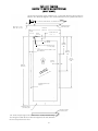
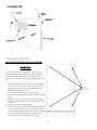
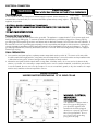
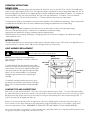
1
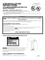
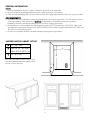
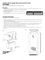
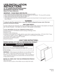
Welcome to Viking Range
Login
Home
Shopping Cart (0)
vuwc151
Cooking
Ventilation Refrigeration
Refrigerator/Freezers
Wine Cellars
Full-Height
Professional Series
Kitchen Cleanup
Outdoor
Countertop Appliances
Cookware
Cutlery
Viking Gear
Accessories
Products > Refrigeration > Wine Cellars > Undercounter/Freestanding > Professional Series > 15" VUWC
Undercounter/Freestanding Wine Cellar
15" Undercounter/Freestanding Wine Cellar VUWC
Professional Series
Designer Series
Full Overlay
Undercounter/Freestanding
Professional Series
Designer Series
Full Overlay
Ice Machines
Beverage Centers
Accessories
Professional Features
Six wire shelves store up to 24 wine bottles horizontally,
keeping corks moist
Shelves are coated to reduce vibration and hold bottles
snugly in place
Full-width shelves pull out for easy access
Shelves can be removed to store larger bottles
Inside temperature can be adjusted from 40-43 degrees F
(4.4-6.1 degrees C) to 64-66 degrees F (17.8-18.9 degrees
C)
Preserves different types of wine at optimal serving
temperature
Related Links
Where to Buy
Brochures
For Viking Owners
For Design Professionals
Contact Us
Ultraviolet-resistant tempered glass and black interior
protect wine from harmful light
Maple wood facings provide additional ultraviolet protection
and may be finished to coordinate with surrounding
cabinetry
Low-intensity interior lighting
Displays wine with minimal heat and light output
Turns on when door is opened or by switch
Keyed door lock provides protection for stored wines (glass
door models)
Professional-Style Construction
Undercounter or freestanding installation
1 of 3
Click on the Image for a larger view
Documentation
Product Specifications
Installation Instructions
Use and Care Manual
Customization Options
Door configurations
Exclusive finishes
Heavy-duty, commercial-style handle
Must be ordered either right- or left-hinge (specify R or L
after model number)
Can be installed as a single unit, double stacked, or
side-by-side in standard-depth residential cabinets
Adjustable leveling legs
Exclusive Finishes
Clear or fluted glass door with stainless steel frame, or solid
door option
Solid door available in Stainless Steel (SS), Black (BK),
White (WH), Almond (AL), Biscuit (BT), Stone Gray (SG),
Graphite Gray (GG), Burgundy (BU), Lemonade (LE), Mint
Julep (MJ), Forest Green (FG), Viking Blue (VB), Cobalt Blue
(CB), and Eggplant (EP)
May be ordered with Brass Trim Option (BR) for nameplate
and door handle/brackets
All brass components have a durable, protective coating
for maintenance-free normal use
Warranty Highlights*
Two-year full covers complete unit
Six-year full - sealed refrigeration system
Twelve-year limited - sealed refrigeration system
Ninety-day limited – cosmetic parts such as glass, painted
items, and decorative items
*Warranty valid on Viking products shipped within the United
States and Canada
Model Numbers
VUWC151R – Clear glass door (right-hinge)
VUWC151L – Clear glass door (left-hinge)
VUWC151FR – Fluted glass door (right-hinge)
VUWC151FL – Fluted glass door (left-hinge)
2 of 3
VUWC151DR – Solid door (right-hinge)
VUWC151DL – Solid door (left-hinge)
Contact Us
Shipping and Returns
Privacy Policy
For Viking Owners
Terms and Conditions
For Design Professionals
Purchase Agreement
3 of 3
International
© 2001 - 2006 Viking Range Corporation. All rights reserved.
USE/INSTALLATION
INSTRUCTIONS
VIKING RANGE CORPORATION
111 FRONT STREET
GREENWOOD, MISSISSIPPI 38930 USA
(662) 455-1200
15” W. UNDERCOUNTER/FREESTANDING WINE CELLAR
Retain for Future Reference
IMPORTANT - PLEASE READ AND FOLLOW
•
•
•
•
•
Before beginning, please read these instructions completely and carefully.
Do not remove permanently affixed labels, warnings, or plates from the product. This may void the warranty.
Please observe all local and national codes and ordinances.
Please ensure that this product is properly grounded.
The installer should leave these instructions with the consumer who should retain for local inspector’s use and for
future reference.
WARNING:
To reduce the risk of fire, electrical shock, or injury when using your wine cellar, follow basic precautions including the
following:
•FOR YOUR SAFETY•
DO NOT STORE OR USE GASOLINE OR OTHER FLAMMABLE VAPORS AND LIQUIDS IN THE VICINITY OF THIS OR
ANY OTHER APPLIANCE. THE FUMES CAN CREATE A FIRE HAZARD OR EXPLOSION.
It is your responsibility to be sure your wine cellar is:
•located so the front is not blocked to restrict incoming or discharge air flow.
•properly leveled.
•located in a well ventilated area.
•connected to the proper kind of outlet, with the correct electric supply and grounding. A 115 volt, 60 Hz, 15 amp
fused electrical supply is required. NOTE: Time delay fuse or circuit breaker is recommended.
•not used by anyone unable to operate it properly.
•used only for its intended purpose.
•properly maintained.
•SAVE THESE INSTRUCTIONS•
PROPER DISPOSAL OF YOUR OLD REFRIGERATION UNIT
DANGER
Suffocation Hazard
Remove doors from your old
refrigeration unit.
Failure to do so can result in
child entrapment which can
cause death or brain damage
IMPORTANT: Child entrapment and suffocation are not problems of the
past. Junked or abandoned refrigeration products are still dangerous,
even if they will sit for “just a few days.” If you are getting rid of your
refrigeration product, please follow the instructions below to help
prevent accidents.
BEFORE YOU THROW AWAY YOUR OLD REFRIGERATION UNIT:
•Take off the doors.
•Leave the shelves in place so that children may not easily climb inside.
41009329
Rev. A
GENERAL INFORMATION
Unpack
1. Remove banding from bottom of carton. Lift carton up and off of the wine cellar
2. Remove all tape and packaging material from the outside and inside of the cabinet.
3. Keep all carton packaging until your wine cellar has been thoroughly inspected and found to be in good condition.
AREA REQUIREMENTS
1. Place unit so the front side will be completely unobstructed to provide proper air flow. The unit may be closed in
on the top and three sides, but the front MUST BE unobstructed for air circulation and proper operation.
Installation should be such that the cabinet can be moved for servicing if necessary.
2. Unit should be in a well ventilated area with temperature above 550F (130C) and below 1100F (430C). Best results
are obtained at temperatures between 650F (180C) and 800F (270C) for built-in models and between 650F (180C) and
900F (320C) for freestanding models.
3. Provisions for electricity should be determined before placing unit in proper place.
UNDERCOUNTER CABINET CUTOUT
A
15” (38.1 cm)*
B
Min. 34 1/2” (87.6 cm)
A
Max. 35 1/8” (89.2 cm)
C
24” (61.0 cm)
B
*15” (38.1 cm) width for cabinet only. If door
is recessed between cabinets, cabinet cutout
must be 15-1/4” (38.7 cm)
C
2
SPECIFICATIONS/DIMENSIONS -
Front View
Professional Models
Basic Electric Data
•115 VAC/60 Hz
•Maximum amps - 3.0
•Approximate Shipping Weight - 110 lbs. (49.5 kg)
Min. 34 1/4”
(87.0 cm)
to
Max. 35”
(88.9 cm)
(with leveling
legs fully
extended.)
30 3/4”
(78.1 cm)
14 3/4” (37.5 cm)
Side View
37 3/16” (94.5 cm)
21 3/16” (53.8 cm)
23 5/8” (60.0 cm)
26 1/8” (66.4 cm)
3
SPECIFICATIONS/DIMENSIONS -
Front View
Designer Models
Basic Electric Data
•115 VAC/60 Hz
•Maximum amps - 3.0
•Approximate shipping weight - 110 lbs (49.5 kg)
Mín.
34 1/4”
(87.0 cm)
Max.
35”
(88.9 cm)
30 3/4”
(78.1 cm)
(with leveling
legs fully
extended.)
14 3/4” (37.5 cm)
Side View
DUWC
Side View
DFUW
37 3/16” (94.5 cm)
37 3/16” (94.5 cm)
21 3/16” (53.8 cm)
21 3/16” (53.8 cm)
23 5/8” (60.0 cm)
23 7/16” (59.5 cm)
24 5/8” ( 62.5 cm)
(to front of locally supplied
custom panel
4
CUSTOM WOOD FRAME INSTALLATION INSTRUCTIONS
(DFUW Model)
Note: Weight of wood panel must not exceed 20 lbs.
Wood Screws
1. A #8 pan head wood screw should be used to properly secure the wood frame. A total of 8 screws will be needed
for a 3 1/2” (8.9 cm) kickplate or 7 screws for a 4” (10.2 cm) kickplate.
2. Only use pan head screws.
Working Material
Wood Screw Size #8
3. DO NOT select a screw that is longer than the wood thickness at
Hardwood
3/32 (0.24 cm)
the screw locations.
Softwood
5/64 (0.20 cm)
4. Use recommended pilot holes for the frame material. (See chart)
Assembling Door Hinge Brackets
(Disregard if hinge brackets are already attached)
1. Attach the top and bottom door hinge brackets to the door with the #10-32 machine screws and a 1/8” allen head
driver as shown in Figure 1 below.
2. Press in the shoulder bushings to the top and bottom door hinge brackets. Make certain that the shoulder is to the
outside of the door as shown in Figure 1 below.
3. Test fit the door to the unit to make certain door will hang correctly. The door is hung correctly when the top of the
door is parallel to the top of the unit. (See Figure 2) Adjustments can be made by loosening the door hinge
machine screws and moving the door hinge brackets on the door.
4. Tighten all four (4) machine screws after adjustments have been made.
5. Remove the door from the unit by removing the units top hinge set screw and angling the door off of the bottom
hinge pin.
Figure 2
Figure 1
This surface parallel to the unit.
(Right hinge door shown
Shoulder Bushing
Door Hinge Bracket
#10-32 Machine
Screw
Door Hinge
Screw Holes
Door Front
Surface
Typical Top and Bottom
Door Hinge Bracket
Assembly
5
Selecting and Preparing the Wood Frame - DFUW Models
FOR A 3-1/2” TOE KICK
(COVERS THE ENTIRE DOOR EXTRUSION)
(LEFT HINGE)
1/4” X 3/8” Deep hinge screw clearance hole. Locate and drill using
door hinge hole after the door has been aligned to the unit and when
the wood is positioned on door
3 7/32”
(8.1 cm)
Mounting surface
(Non-face) side
Min. 5/8” (1.7 cm)
Max. 3/4” (1.9 cm)
14 15/16”
(36.4 cm)
7 5/32” (18.2 cm)
15/32” (1.2 cm)
Dia. hole
15./2” (1.2 cm)
23/32”
(1.8 cm) TYP
13/16” (2.1 cm)
counterbore 7/16”
(1.1 cm) deep
1 23/32” (4.4) cm min.
width to cover door
extrusion
30 5/16”
(77.0 cm)
7 13/16”
(19.8 cm)
TYP
15 5/32”
(38.5 cm)
TYP
23/32”
(1.8 cm)
TYP
22 1.2”
(57.2 cm)
TYP
OF
IEW NEL
V
A
CK Y P
BA RLA
E
OV
Pre-drilled piolt holes 8 places
Mounting surface
(non-face) side
Mounting surface
(non-face) side
1/4” X 3/8” Deep hinge screw clearance hole. Locate and drill using
door hinge hole after the door has been aligned to the unit and
when the wood is positioned on door
6
OPTIONAL FOR 4” TOE KICK
TO MATCH EXISTING CABINETRY TOE KICK HEIGHT
(LEFT HINGE)
1/4” X 3/8” Deep hinge screw clearance hole. Locate and drill using
door hinge hole after the door has been aligned to the unit and when
the wood is positioned on door
3 7/32”
(8.1 cm)
Mounting surface
(Non-face) side
Min. 5/8” (1.7 cm)
Max. 3/4” (1.9 cm)
14 15/16”
(36.4 cm)
7 5/32” (18.2 cm)
15/32” (1.2 cm)
Dia. hole
15/32” (1.2 cm)
23/32”
(1.8 cm) TYP
13/16” (2.1 cm)
counterbore 7/16”
(1.1 cm) deep
1 23/32” (4.4) cm min.
width to cover door
extrusion
29 13/16”
(75.7 cm)
7 13/16”
(19.8 cm)
TYP
15 5/32”
(38.5 cm)
TYP
23/32”
(1.8 cm)
TYP
22 1.2”
(57.2 cm)
TYP
OF
IEW NEL
V
A
CK Y P
BA RLA
E
OV
Pre-drilled piolt holes 7 places
Mounting surface
(non-face) side
Mounting surface
(non-face) side
1/4” X 3/8” Deep hinge screw clearance hole. Locate and drill using
door hinge hole after the door has been aligned to the unit and
when the wood is positioned on door
7
FOR 3-1/2” TOE KICK
(COVERS THE ENTIRE DOOR EXTRUSION)
(RIGHT HINGE)
1/4” X 3/8” Deep hinge screw clearance hole. Locate and drill using door hinge hole
after the door has been aligned to the unit and when the wood is positioned on door
3 7/32”
(8.1 cm)
Mounting surface
(Non-face) side
Min. 5/8” (1.7 cm)
Max. 3/4” (1.9 cm)
14 15/16”
(36.4 cm)
15/32”
(1.2 cm)
7 5/32” (18.2 cm)
15/32”
(1.2 cm)
Dia. hole
23/32”
(1.8 cm) TYP
13/16” (2.1 cm) counterbore 7/16”
(1.1 cm) deep
1 23/32” (4.4) cm min. width to cover
door extrusion
7 13/16”
(19.8 cm)
TYP
15 5/32”
(38.5 cm)
TYP
22 1.2”
(57.2 cm)
TYP
23/32”
(1.8 cm)
TYP
30 5/16”
(77.0 cm)
OF
IEW NEL
V
A
CK Y P
BA RLA
E
OV
Pre-drilled piolt holes 8 places
Mounting surface
(non-face) side
Mounting surface
(non-face) side
1/4” X 3/8” Deep hinge screw clearance hole. Locate and drill using
door hinge hole after the door has been aligned to the unit and when
the wood is positioned on door
8
OPTIONAL 4” TOE KICK
TO MATCH EXISTING CABINETRY TOE KICK HEIGHT
(RIGHT HINGE)
1/4” X 3/8” Deep hinge screw clearance hole. Locate and drill using door hinge hole
after the door has been aligned to the unit and when the wood is positioned on door
3 7/32”
(8.1 cm)
Mounting surface
(Non-face) side
Min. 5/8” (1.7 cm)
Max. 3/4” (1.9 cm)
14 15/16”
(36.4 cm)
15/32”
(1.2 cm)
7 5/32” (18.2 cm)
15/32”
(1.2 cm)
Dia. hole
23/32”
(1.8 cm) TYP
7 13/16”
(19.8 cm)
TYP
13/16” (2.1 cm) counterbore 7/16”
(1.1 cm) deep
1 23/32” (4.4) cm min. width to cover
door extrusion
15 5/32”
(38.5 cm)
TYP
22 1.2”
(57.2 cm)
TYP
23/32”
(1.8 cm)
TYP
29 13/16”
(75.7 cm)
OF
IEW NEL
V
A
CK Y P
BA RLA
E
V
O
Pre-drilled piolt holes 7 places
Mounting surface
(non-face) side
Mounting surface
(non-face) side
1/4” X 3/8” Deep hinge screw clearance hole. Locate and drill using
door hinge hole after the door has been aligned to the unit and when
the wood is positioned on door
Attaching the Handle
Attach the handle of your choice by drilling mounting holes through panel. Countersink or counterbore holes from back
side of panel for handle screw heads to be flush.
9
Attaching the Wood Frame to the Door - DFUW Models
1. If the door is attached to the unit, remove by unscrewing the top allen head set screw at the top hinge. Remove
the door by angling the door off of the bottom hinge pin.
2. Install the supplied lock body into the wood panel. Secure the lock body by using the supplied 15mm lock
retaining nut. Screw the lock retaining nut on the lock body’s threaded section. Make sure the lock’s key slot is
vertical, then tighten the nut with a deep well socket.
3. Peel back the door gasket to expose the screw holes and lock location hole.
4. Set the wood frame flush to the front of the door in the desired location. Clamp the wood frame to the door if
necessary. Check to make sure the back of the lock in the wood frame lines up with the hole in the door.
5. Insert the wood screws through the back of the door into the pilot holes in the wood frame and tighten.
6. Assemble the door lock’s phillips head screw, the lock extension, and lock cam. Mount them to the back of the
lock body. The cam should be oriented vertically. Tighten the phillips head screw to secure the lock assembly.
7. Reinstall the door gasket by pressing into the door channel. Make certain the corners are inserted fully. Insert the
key into the lock and make sure the lock operates properly
8. Install the door to the unit. Use the supplied plastic washer as shown in the figure below.
9. Realigning the door may be necessary. Any final door adjustments can be made using a 1/8” allen head driver to
adjust the door’s hinges. (See figure below)
10. Attach the door light striker plate as shown using the 5/16” hex or phillips head screws provided. Make certain the
light is able to turn on and off when the door is opened and closed.
11. Attach the door to the unit by reversing step number 1 above.
12. Insert the key into the lock and verify that the lock cam works properly with the catch bracket on the cabinet front.
Hinge Hardware Installation
Details
CAUTION
Door can become
disengaged if washers
are not installed.
CAUTION
Door can become
disengaged if
washers are not
installed.
Cabinet
Hinge
(2) Nylon
hardware
components at
top hinge
Magnetic door gasket
3/8” clearance holes
for frame wood screws
- 8 holes
5/8”x 7/32” ID washer
Shoulder
bushing
Wood
Frame
Door Hinge
Door Hinge
Rear of Door
CAUTION
Door may not swing properly
if all nylon components are
not installed as shown
Shoulder bushing
3/4” OD x 7/16”
ID Washer
3/4” OD x 1/4” ID
Washer
Wood Frame
(3) Nylon hardware
components at
bottom hinge
Bottom Hinge Cover
Top Hinge Cover
Door hinge adjustment
screws
Attached wood
frame
10
1/8” allen head screws for hinge
adjustment
Door light striker plate
Bottom of
door
Lock Installation Details
Lock Body
Lock Cam
Phillips Screw
KEY
Lock Extension
oor
ss D
Gla
el
Pan
d
o
Wo
Door Gasket
Lock Retainer Nut
leg leveler installatin
READ BEFORE INSTALLING LEG LEVELERS
WARNING
Do not lay unit on top, side, back, or front. If unit is
accidentally laid in any position other than right side
up, then the unit must remain in the right side up
position for at least 24 hours before plugging the unit
in.
1. Tip unit backwards so there is (1) foot of clearance
on front of the unit. Have someone to assist you in
tilting the unit, to prevent it from falling on you
while installing the leg levelers.
2. Screw front two leg levelers into the screw
impressions. Leg levelers should be screwed in until
snug.
3. Repeat steps 1 & 2, with the exception of tipping
the unit forwards now, to screw in the back two leg
levelers.
4. Your leg levelers are now installed.
5. The unit should be level from front to back and side
to side. If floor conditions do not allow the unit to
sit level, adjust leg leveler(s) by turning the required
leg leveler(s) counter-clockwise to increase their
height and clockwise to reduce their height.
Screw
Impressions
11
ELECTRICAL CONNECTION
WARNING
Electrical Shock Hazard
Failure to follow these instructions could result in fire or electrical shock.
Electrical Requirements
A 115 volt, 60 Hz, AC only 15 amp fused electrical supply is required. (A time delay fuse or
circuit breaker is recommended.) It is recommended that a separate circuit, serving only this
appliance, be provided.
Power Supply
with 3-prong
grounding plug
Grounding type
wall receptacle
•ELECTRICAL GROUND IS REQUIRED ON THIS APPLIANCE.
•DO NOT UNDER ANY CIRCUMSTANCES REMOVE THE POWER SUPPLY CORD GROUND
PLUG.
•DO NOT USE AN EXTENSION CORD
Recommended Grounding Methods
For your personal safety, this wine cellar must be grounded. This appliance is equipped with a 7’ (2.1m) power supply cord
having a 3-prong grounding plug. To minimize possible shock hazard, the cord must be plugged into a mating 3-prong
grounding type wall receptacle grounded in accordance with the National Electrical Code and local codes and ordinances. If
the circuit does not have a grounding type receptacle, it is the responsibility and obligation of the customer to exchange the
existing receptacle in accordance with the National Electrical Code and applicable local codes and ordinances. The third
ground plug SHOULD NOT, under any circumstances, be cut or removed. All UL listed refrigerated products are equipped
with this type of plug.
FINAL PREPARATION
1. Some stainless steel parts may have a plastic protective wrap which must be peeled off. The interior of the wine cellar
should be washed thoroughly with hot, soapy water, rinsed and wiped dry to remove film residue and any installation dust
or debris before being used. Solutions stronger than soap and water are rarely needed.
2. All stainless steel parts should be wiped with hot soapy water. If buildup occurs, do not use steel wool, abrasive cloths,
cleaners, or powders. If it is necessary to scrape stainless steel to remove encrusted materials, soak with hot, wet cloths to
loosen the material, then use a wood or nylon scraper. Do not use a metal knife, spatula, or any other metal tool to scrape
stainless steel; scratches are almost impossible to remove.
WIRING DIAGRAM
UNDERCOUNTER/FREESTANDING 15” W. WINE CELLAR
WARNING: ELECTRICAL
GROUNDING
INSTRUCTIONS
This appliance is equipped with a
three prong grounding plug for
your protection against shock
hazard and should be plugged
directly into a properly grounded
three prong receptacle. Do not
cut or remove the grounding
prong from this plug.
12
OPERATING INSTRUCTIONS
Setting the Controls
The total available temperature range of the unit is from 40 - 430F (4.4 -- 6.10C) to 64 - 660F (17.8 - 18.90C). The middle range
on the control is approximately 530F (11.70C). The higher the number selected, the cooler the temperature within the unit. As
with any refrigeration product, there is a slight temperature variance at different locations within the cabinet. For example, the
coolest area will be in the rear of the lowest shelf. The area on the top shelf will be 3 - 70F warmer. This is the warmest
location in the cabinet. The area in the front will be 1 - 50F warmer than the area in the rear of the shelves.
To start your wine cellar, use a screwdriver to turn the control clockwise to the middle thermostat setting. Once the wine cellar
is loaded allow at least 48 hours for the unit to stabilize before making any adjustments to the initial setting.
Tips and Suggestions
•After making a temperature adjustment, allow 24 hours for your wine cellar to reach a new temperature setting.
•The motor will start and stop often. It must do this to maintain the temperature setting.
•Unplug the wine cellar before working on anything with the electrical system.
•Exercise caution when sweeping, vacuuming, or mopping near the front of the unit. Damage to the grill and/or the light
fixture switch can occur.
INTERIOR LIGHT
The interior light allows you to view your wine cellar contents. When the switch is in the “OFF” position, the light will come on
only when the door is opened. In the “ON” position, the light remains on continuously
LIGHT ASSEMBLY REPLACEMENT
WARNING
Failure to disconnect the power cord when changing the
light assembly may result in electric shock.
Green
ground wire
NOTE: Please contact your local Viking Range
Corporation parts distributor or dealer to order new
light assembly.
To replace the light, first disconnect the wine cellar’s
power cord. Next, remove both the green ground wire
screw located on the left of the light assembly and the
other screw located on the right of the light assembly
with a 5-16” hex head screwdriver. (See drawing).
Unplug the light unit and remove complete light
assembly.
Light
assembly
Hex head
screw
Plug
Hex head
screw
To install the new light assembly, screw in the green
ground wire screw and the screw located on the right
with a 5/16” hex head screwdriver and plug the light
unit in.
LOADING TIPS AND SUGGESTIONS
Each of the six racks hold four bottles. The necks of the bottles alternate front to back. To aid in loading/unloading,
the racks pull forward to allow easier access to the rear bottles. Bottom racks may be removed for storing “jug’” wines.
Magnums and other large bottles may be stored by removing the rack directly above the intended storage rack. To
remove the racks, lift up slightly and slide out.
Bottles on the top rack directly under the light will be exposed to slightly higher temperature when the light is on.
Store red wines on the upper racks where the temperature is higher and white wines on the middle or lower racks
where the temperature is lower. REMEMBER TO TURN OFF THE LIGHT WHEN IT IS NO LONGER NEEDED.
Store wines intended for everyday use on the front half of the racks where labels are completely visible and place wines
for aging or long term storage in the rear half of the rack.
13
ENERGY SAVING TIPS
•Reduce door openings.
•Close the door as soon as you can.
•Keep the condenser coils on bottom of the wine cellar clean. (See “Cleaning and Maintenance”.)
•Adjust the temperature control to a warmer setting when practical.
•Install unit away from the stove or other heat sources.
CLEANING AND MAINTENANCE
Any piece of equipment works better and lasts longer when maintained properly and kept clean.
Condenser
The condenser tubing inside the cabinet does not require frequent cleaning; however, satisfactory cooling depends on
adequate ventilation over the coils. Be sure that nothing obstructs the required air flow openings in front of the cabinet.
Spiders and insects can nest in and around the wine cellar causing damage to the unit. Frequently brush or vacuum lint
and dirt from the condenser coils for efficient performance by unscrewing the grill on the bottom front of cabinet.
Cabinet
The cabinet can be washed with mild soap and water and thoroughly rinsed with clear water. Never use abrasive scouring
powders.
Interior
Wash interior compartment with mild soap and water. Do not use abrasive powder, solvent, polish cleaner or undiluted
detergent.
Stainless Steel Parts
All stainless steel parts should be wiped regularly with hot soapy water. Use a liquid cleaner designed for stainless steel
when soapy water will not do the job. Do not use steel wool, abrasive cloths, cleansers, or powders. Do not permit citrus
or tomato juice to remain on stainless steel surfaces, as citric acid will permanently discolor stainless steel.
Brass Parts
CAUTION: All brass parts have an epoxy coating. DO NOT USE BRASS OR ABRASIVE CLEANERS ON THE BRASS
PARTS. All brass parts should be wiped regularly with hot soapy water. When hot soapy water will not do the job, use
every day non-abrasive household cleaners.
Glass Door
Use a glass cleaner or mild soap and water with soft cloth to clean the glass door. Do not use any abrasive powders.
Door Gasket
The vinyl gasket may be cleaned with mild soap and water, a baking soda and water solution, or a mild scouring powder.
On full overlay models, use caution when cleaning near the logo area.
Painted Surfaces
Wash with warm soapy water. DO NOT USE steel wool, abrasive cleansers, ammonia, acids or commercial oven cleaners
which may damage the finish.
14
TROUBLESHOOTING CHART
Problem
Possible Cause/Solution
Odor in cabinet
Noisy operation/cabinet vibrates
Cabinet light not working
Appliance will not run
Interior needs cleaning.
Cabinet not level; weak floor.
Bulb burned out; no power at outlet.
Temperature control to “OFF”; line cord not plugged in; no power at
electrical outlet; house fuse blown.
Prolonged door openings; control set too cold; condenser needs
cleaning
Too many door openings; prolonged door openings; (hot, humid
weather increases condensation)
(Hot, humid weather increases condensation); control improperly set.
Control improperly set; faulty thermometer; (relocate thermometer to
center of cabinet and recheck)
Appliance runs too long
Moisture collects inside
Moisture collects to outside surface
Interior too hot/too cold
SERVICE INFORMATION
It is assumed that your wine cellar has been properly installed in accordance with all specifications and local codes and the
appliance has been properly grounded. If your wine cellar should fail to operate, review the troubleshooting chart before
calling for service.
If service is required:
1. Call your dealer or authorized service agency. The name of the authorized service agency can be obtained from the
dealer or distributor in your area.
2. Have the following information readily available:
•Model number
•Serial number
•Date of purchase
•Name of dealer from whom purchased
If you are unable to obtain the name of an authorized service agency, or if you continue to have service problems, contact
Viking Range Corporation at (888) 845-4641 or write to:
VIKING PREFERRED SERVICE
111 Front Street
Greenwood, Mississippi 38930 USA
Record the following information indicated below. You will need it if service is ever required. The serial number and
model number for your wine cellar is located on the front of the unit at the base of the door frame.
Model Number
Serial Number
Date of Purchase
Date Installed
Dealer’s Name
Address
If service requires installation of parts, use only authorized parts to ensure protection under the warranty.
This manual should remain with the wine cellar for future reference.
15
UNDERCOUNTER/FREESTANDING WINE CELLAR WARRANTY
TWO YEAR FULL WARRANTY
Built-in/freestanding undercounter wine cellars and all of their components and accessories, except as detailed below*, are warranted to be free from defects in material or
workmanship under normal household use for a period of two (2) years from the date of original retail purchase. Viking Range Corporation, warrantor, agrees to repair or
replace, at its option, any part which fails or is found to be defective during the warranty period
*Painted and decorative items are warranted to be free from defective materials or workmanship for a period of ninety (90) days from the date of original retail purchase.
ANY DEFECTS MUST BE REPORTED TO THE SELLING DEALER WITHIN NINETY (90) DAYS FROM DATE OF ORIGINAL RETAIL PURCHASE.
SIX YEAR FULL WARRANTY
Any sealed refrigeration system component, as listed below, is warranted to be free from defective materials or workmanship in normal household use during the third
through the sixth year from the date of original retail purchase. Viking Range Corporation, warrantor, agrees to repair or replace, at its option, any part which fails or is found
to be defective during the warranty period.
Sealed Refrigeration System Components:
Compressor, Evaporator, Condenser, Connecting Tubing, Dryer/Strainer
TWELVE YEAR LIMITED WARRANTY
Any sealed refrigeration system component, as listed above, which fails due to defective materials or workmanship in normal household use during the seventh through the
twelfth year from the date of original retail purchase will be repaired or replaced, free of charge for the part itself, with the owner paying all other costs, including labor.
This warranty extends to the original purchaser of the product warranted hereunder and to each transferee owner of the product during the term of the warranty.
This warranty shall apply to products purchased and located in the United States and Canada. Products must be purchased in the country where service is requested.
Warranty labor shall be performed by an authorized Viking Range Corporation service agency or representative. Warranty shall not apply to damage resulting from abuse,
accident, natural disaster, loss of electrical power to the product for any reason, alteration, improper installation, improper operation or repair or service to the product by
anyone other than an authorized Viking Range Corporation service agency or representative. Warranty shall not apply to damage resulting from indoor units being used in
outdoor situations. This warranty does not apply to commercial usage. Warrantor is not responsible for consequential or incidental damage whether arising out of breach of
warranty, breach of contract, or otherwise. Some jurisdictions do not allow the exclusion or limitation of incidental or consequential damages, so the above limitation or
exclusion may not apply to you.
Owner shall be responsible for proper installation, providing normal care and maintenance, providing proof of purchase upon request, and making the appliance reasonably
accessible for service. If the product or one of its component parts contains a defect or malfunction during the warranty period, after a reasonable number of attempts by
the warrantor to remedy the defects or malfunctions, the owner is entitled to either a refund or replacement of the product or its component part or parts. Replacement of a
component part includes its free installation. Warrantor’s liability on any claim of any kind, with respect to the goods or services covered hereunder, shall in no case exceed
the price of the goods or service or part there of which gives rise to the claim.
WARRANTY SERVICE: Under the terms of this warranty, service must be performed by a factory authorized Viking Range Corporation service agent or representative.
Service will be provided during normal business hours, and labor performed at overtime or premium rates shall not be covered by this warranty. To obtain warranty service,
contact the dealer from whom the product was purchased, an authorized Viking Range Corporation service agent, or Viking Range Corporation. Provide model and serial
number and date of original purchase. For the name of your nearest authorized Viking Range Corporation service agency, call the dealer from whom the product was
purchased or Viking Range Corporation. IMPORTANT: Retain proof of original purchase to establish warranty period.
The return of the Owner Registration Card is not a condition of warranty coverage. You, however, should return the Owner Registration Card so that Viking Range
Corporation can contact you should any question of safety arise which could affect you.
Any implied warranties of merchantability and fitness applicable to the above described undercounter wine cellar are limited in duration to the period of coverage of the
applicable express written limited warranties set forth above. Some jurisdictions do not allow limitations on how long an implied warranty lasts, so the above limitation may
not apply to you. This warranty gives you specific rights, and you may also have other rights which may vary from jurisdiction to jurisdiction.
Viking Range Corporation
111 Front Street • Greenwood, Mississippi USA • 38930 (662) 455-1200
www.vikingrange.com
Specifications subject to change without notice
F20345
(PS0405VR)
GENERAL INFORMATION
Unpack
1. Remove banding from bottom of carton. Lift carton up and off of the wine cellar
2. Remove all tape and packaging material from the outside and inside of the cabinet.
3. Keep all carton packaging until your wine cellar has been thoroughly inspected and found to be in good condition.
AREA REQUIREMENTS
1. Place unit so the front side will be completely unobstructed to provide proper air flow. The unit may be closed in
on the top and three sides, but the front MUST BE unobstructed for air circulation and proper operation.
Installation should be such that the cabinet can be moved for servicing if necessary.
2. Unit should be in a well ventilated area with temperature above 550F (130C) and below 1100F (430C). Best results
are obtained at temperatures between 650F (180C) and 800F (270C) for built-in models and between 650F (180C) and
900F (320C) for freestanding models.
3. Provisions for electricity should be determined before placing unit in proper place.
UNDERCOUNTER CABINET CUTOUT
A
15” (38.1 cm)*
B
Min. 34 1/2” (87.6 cm)
A
Max. 35 1/8” (89.2 cm)
C
24” (61.0 cm)
B
*15” (38.1 cm) width for cabinet only. If door
is recessed between cabinets, cabinet cutout
must be 15-1/4” (38.7 cm)
C
2
SPECIFICATIONS/DIMENSIONS -
Front View
Professional Models
Basic Electric Data
•115 VAC/60 Hz
•Maximum amps - 3.0
•Approximate Shipping Weight - 110 lbs. (49.5 kg)
Min. 34 1/4”
(87.0 cm)
to
Max. 35”
(88.9 cm)
(with leveling
legs fully
extended.)
30 3/4”
(78.1 cm)
14 3/4” (37.5 cm)
Side View
37 3/16” (94.5 cm)
21 3/16” (53.8 cm)
23 5/8” (60.0 cm)
26 1/8” (66.4 cm)
3