1
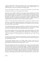
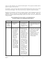
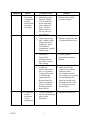
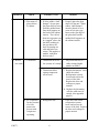
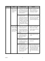
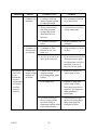
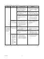
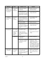
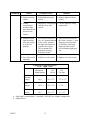
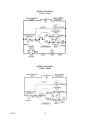
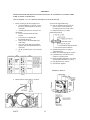
F90571
TABLE OF CONTENTS
General Information--------------------------------------------------------------------------------
4
Most often Misdiagnosed Problem---------------------------------------------------------------
4
Troubleshooting Guide
1.
Interior too Cool or Contents Freezing-------------------------------------- 6
2.
Interior too Warm (Compressor Operates)--------------------------------- 8
3.
Excessive Frost Build-up on Evaporator. (Interior Temperatures
Normal and Frost Pattern Uniform.)----------------------------------------- 10
4.
Compressor, Fan and Interior Light do not Function--------------------- 11
5.
Interior Light Functions but Compressor will not Run------------------- 12
6.
Compressor Runs, Fan does not Run------------------------------------------ 12
7.
Fan Runs, but Compressor does not Run------------------------------------- 12
8.
Interior Light will not turn OFF when Door is Closed--------------------- 12
Thermostat Specifications---------------------------------------------------------------------------- 13
Wiring Diagram---------------------------------------------------------------------------------------- 14
Appendix: Solid State Control---------------------------------------------------------------------- 15
F90571
3
VIKING RANGE ALL-REFRIGERATION MODELS
VUWC140/150—VUAR140/150—VRBD—VUBD
The all-refrigerator product line encompasses traditional all-refrigerators, beverage storage allrefrigerators with temperature barriers to create different temperature zones, refrigerator
beverage dispensers, and wine storage refrigerators.
All these models employ an evaporator plate for cooling the cabinet interior and an evaporator
plate sensing thermostat to control the compressor operation and therefore, the interior
temperature.
A cycle defrost system is also used on all these models. The plate sensing thermostat is designed
such that at the end of each compressor run cycle, the evaporator plate must “warm-up” above a
freezing temperature before the compressor will restart. During this “warm-up” period, any
accumulated frost on the evaporator melts and drips off the evaporator plate into drip channels
and a drip tray. From the drip tray, a drain tube carries the defrost water to a pan in the
mechanical compartment. There, condenser fan air movement and compressor heat evaporate
the water.
Most Often Misdiagnosed Problem
Sealed refrigeration system leaks are the most often misdiagnosed problem on the Viking allrefrigerator models. The interaction between the evaporator sensing thermostat, the mounting
location of the thermostat thermobulb, and a low refrigerant condition within the evaporator,
yields a condition in which the cabinet interior air temperature drops below freezing and stored
commodities become frozen.
End users respond to the colder interior temperatures by adjusting the thermostat knob to a
warmer setting, until they reach the warmest available. When their stored commodities continue
to freeze at the warmest setting, they call for service. The end user states the problem as “the
thermostat is set at its warmest setting yet everything inside freezes.”
This leads most service technicians to suspect a bad thermostat. When the technician examines
the unit and finds that the compressor runs continuously, the tentative diagnosis is confirmed.
The technician’s diagnosis is that the thermostat is not functioning properly and he replaces it.
When this does not correct the problem, often the thermostat is replaced a second time because
the technician believes the first replacement thermostat might have also been defective. By this
time, the end user is upset because the technician cannot repair his unit and the technician is
contacting the Viking Customer Services Department to inform us that he has received two
“defective” thermostat service assemblies!
What a mess! Let’s back-up to the beginning to determine where this service call went wrong.
When the end user stated the problem as “the thermostat is set at its warmest setting yet
everything inside freezes”, the technician automatically thought, “too much run time”, probably
bad thermostat. But the problem was actually a low refrigerant charge or leak. Typically, when
90571
4
Customers complain about a refrigerator operating too cold, we don’t usually think about a low
refrigerant charge or leak. A low charge or leak typically causes the opposite problem – the
interior becomes too warm as the system runs out of cooling capacity.
The rest of the problem is the “unique” way, some call it the “backwards” way, that the Viking
all refrigerator models react to a low refrigerant volume condition.
When there is a low refrigerant condition in the unit, the gas volume is insufficient to fill all the
tracks in the plate evaporator. As a result, areas not filled with gas do not achieve the very cold
plate sensing thermostats cut-out temperatures. Therefore, whenever the remaining refrigerant
gas volume is not sufficient to fill the area of the evaporator where the thermostat’s sensing
thermobulb is mounted, the compressor runs continuously. Usually the cooling capacity of the
remaining portion of the evaporator which still contains refrigerant, is sufficient to achieve air
temperatures below freezing in the unit when the compressor runs continuously.
Therefore, when dealing with plate sensing thermostats, as opposed to air temperature sensing
thermostats, we must adjust our thinking about how the sealed refrigeration system can react to a
low or leak condition. The conditions described above are representative of a slow leak where
the system still retains a partial charge.
The recommended diagnostic approach for complaints of “operation too cold on lowest setting”
is to insure the compressor is operating and then open the unit door. Allow the door to remain
open for about 5 minutes and observe the frost pattern that forms on the evaporator.
On a properly charged unit, the frost pattern should be continuous and uniform over the entire
surface of the evaporator. The frost pattern should extend from the left-hand wing of the
evaporator across the back segment and around to the right-hand wing. If this frost pattern is
present, the thermostat or its thermo-bulb mount are possible the source of the too cold
condition.
On a unit with a low charge or leak condition, the frost pattern, if present, will typically cover the
left wing and perhaps a part of the back. It will not be present on the entire back or right wing of
the evaporator plate as viewed.
The thermo-bulb mounting location on the VRBD—VUBD—VUAR is at the top of the
evaporator plate on the portion across the rear of the cabinet. On the model VUWC, the thermobulb is mounted to the right wing of the evaporator plate as viewed.
When an incomplete frost pattern is present which does not cover the area where the thermo-bulb
is mounted, the problem is a leak or low refrigerant charge. Changing the thermostat will not
correct the “too cold” condition. Locating the leak, sealing it and evacuation and recharging the
system is the only permanent solution. Leak check all braze joints on the refrigerant tubes and
check all sealed system components for the source of the leak. Include the tubes themselves, the
process stub close-out welds and the copper-to-aluminum braze way joints at the evaporator inlet
and outlet. The braze way welds are difficult to leak check in the cabinet. If the rest of the
system has been thoroughly checked and no leaks have been found, the braze ways are the likely
F90571
5
source of a leak. The braze ways cannot be brazed/repaired. The evaporator assembly must be
replaced to repair a leak in this area.
Occasionally, corrosion develops under the thermo-bulb mounting clamp causing a leak, so leak
check this area thoroughly. Also, if this is the leak source, replace the evaporator assembly.
Hopefully, this information will help you properly diagnose sealed refrigeration system leak
conditions which you encounter on Viking all-refrigerator models in the field. When these
problems are properly diagnosed and promptly repaired, the customer, the service technician and
Viking all benefit.
TROUBLESHOODTING FOR VIKING ALL-REFRIGERATOR
AND WINE STORAGE ALL-REFRIGERATOR MODELS
PROBLEM
CHECK
1. Interior too a. Thermostat
cold or
setting
contents .
freezing.
b. The evaporator
for the presence
of a uniform
frost pattern
Is the frost
confined to left
wing and left
side of the
back? Note
compressor
should be
operating for at
least 5 minutes
with door open
to perform this
check. See
previous page
for explanation
unique problem.
F90571
POSSIBLE CAUSE
REMEDY
1. Thermostat set to
too cold of a
setting for ambient
conditions.
1. Adjust thermostat to warmer
setting (lower number on
knob)
1. Refrigerant leak
or low refrigerant
charge in the
sealed system.
Refrigerant volume
is evaporator is not
sufficient to cool
the region of the
plate where the
evaporator plate
sensing thermostat’s thermo-bulb
mounts. Therefore
the control thermostat never reaches
its cut-out
temperature and
the compressor
Operates 100% of
the time. The
remaining evaporator volume is
sufficient to cool
the air temperature
below freezing.
1. locate and correct cause of
refrigerant leak. Replace
drier, evaporator, and
Recharge sealed
refrigerant system with
the proper amount of
charge as listed on the
unit’s data plate.
6
PROBLEM
CHECK
c. Thermostat
(compressor
control)
thermo-bulb
mounting
or routing.
d. Compressor
control
thermostat
cut-out
temperature.
F90571
POSSIBLE CAUSE
REMEDY
1. Mounting location
incorrect. Model
VUCW should be
on the right wing
of the evaporator
plate. All other
models mount at
rear top center of
the evaporator.
1. Relocate thermo-bulb
to proper location
2. Thermostat sensing
tube (capillary tube)
resting on or above
compressor dome
in mechanical
compartment causing
false sensing.
2. Reroute sensing tube clear
of compressor dome area.
3. Thermostat
thermo-bulb
mounting bracket
not secure, causing
false sensing.
3. Securely tighten
thermo-bulb mounting
bracket.
4. Insufficient
thermo-bulb contact
area. on evaporator
U-shaped loop with
3-inch long legs
required bracket
Bracket should be
located at midpoint
of each 3-inch leg.
Both legs secured
under bracket
4. Adjust thermo-bulb
contact area to achieve
sufficient contact.
A U-shaped loop with
3-inch long legs is required.
The mounting bracket
should be located at the
mid point of each 3-inch
leg. Both legs secured
under bracket.
1. Cut-out temperature
too low due to internal
failure in the
thermostat
1. Replace the thermostat
7
PROBLEM
2. Interior
too warm
CHECK
POSSIBLE CAUSE
e. Placement of
glass shelves
in cabinet
1. If white rubber “shelf
1. Properly place the glass
bumper” do not space
shelves in the unit. White
the glass shelf out away
rubber “shelf bumper”
from the molded innermust be placed so as to
liner shelf supports on
create an air space gap
the back of the cabinet
between the rear edge of
interior. The cold air
the glass shelf and the
from the evaporator can
molded shelf supports on
be “trapped” above the
the cabinet interior.
the shelf resulting in
the area above the
shelf becoming too
cold and below too
warm. (This applies to
models with glass
shelves only.)
a. Thermostat
1. Thermostat set to too
1. Adjust thermostat, to a
low (warm) of a setting.
colder setting (higher
number on knob).
2. Thermostat failed,
cutting compressor
off too soon.
b. the evaporator 1. Refrigerant leak.
for the presence
of a frost
pattern not
present with
compressor
operating.
F90571
REMEDY
8
2. Replace thermostat. Leak
check the sealed
Refrigeration system.
Locate and correct the
source of the leak.
Replace the drier and
recharge to proper
amount.
2a. Replace the thermostat
with the solid state AC
control..(See appendix
page15).
1. Leak check the sealed
refrigeration system.
locate and correct the
source of the leak. Replace
the drier and recharge to
proper amount.
PROBLEM
CHECK
c. High and low
side pressure
in the sealed
system.
POSSIBLE CAUSE
REMEDY
1. Compressor valve failure, 1. Replace compressor and
preventing compressor
drier, evacuate and
from developing required
recharge with refrigerant
refrigerant pressures for
to the proper amount.
system operation.
2. Restriction in the sealed
refrigerant system
causing high compressor
discharge pressures and
low pressure or vacuum
Conditions on the suction
side. Pressure does not
equalize quickly when
the compressor is turned
off.
d. Interior light-- 1. Striker plate on bottom
does it remain
of door not present or
on with door
not positioned properly
closed, adding
to depress light switch in
heat to the
grille area when door is
closed.
2. Locate the restriction and
correct the cause. Evacuate,
replace drier and recharge
the sealed refrigeration
system to the proper level.
1. Replace or install striker
plate on door so light
switch is depressed when
door is closed.
2. Failed light activation
switch not turning off
light when switch is
depressed.
2. Replace light activation
switch.
3. Wiring connection to or
from light activation
switch improperly wired
bypassing switch.
3. Correct improper wiring
connection.
4. Door light activation
4. Place over-ride switch in
switch over-ride switch
the “door” position. Verify
in the “on” position
light goes out when door
permitting light to remain
is closed by depressing
“on” with door closed.
Light activation switch
(Present on some but
and confirming light goes
not all models.)
out.
F90571
9
PROBLEM
CHECK
e. Condenser fan
operation.
f. Condenser air
flow blocked
or restricted.
3.Excessive
a. Cabinet for
frost builtproper sealing
Up on
(absence of
Evaporator
air leaks).
(interior
temperatures
are normal
and frost
pattern is
uniform).
POSSIBLE CAUSE
REMEDY
1. Condenser fan blade
jammed against shroud
or otherwise bound.
1. Free condenser fan blade
so it rotates freely.
2. Wiring connection to
and from fan motor,
terminal block and
thermostat loose or
incorrect.
2. Correct loose or incorrect
wiring connections.
3. Condenser fan motor
failed.
3. Replace condenser fan
Assembly.
1. Condenser air flow
blocked by dirt, lint,
trash , etc.
1. Clean condenser to restore
air flow.
2. Air flow in or out of toe
space grille restricted.
2. Clear restriction to air flow
Through toe space grille.
No obstruction to air flow
permitted in an area 3
feet out from the grille.
1, Exterior door of unit not
hanging straight,
preventing proper gasket
sealing.
1. Install door shim kit to
correct hang of door.
2. Door hinges bent.
2. Install new hinge kit to
correct hang of door.
Door shims may also be
required. See hinge and
Shim installation
instructions.
3. Air leaks at locations
3. Seal around these entry
where refrigerant line,
points with refrigeration
electrical wiring or
putty (permagum) to
thermostat capillary tubes
eliminate air leaks.
enter cabinet interior.
F90571
10
PROBLEM
CHECK
POSSIBLE CAUSE
4. Air leaks around door
gasket due to physical
contour of gasket.
4. Reform gasket using heat
to achieve a complete
seal.
5 Door gasket torn or has
lost magnetism.
5. Replace gasket if stiff
or has weak magnetism.
6. Damage to cabinet front
flange (gasket sealing
area).
6
b. Extended or
1. Extended or too frequent
too frequent
door openings allow
door openings.
warm, moist air to reach
cold evaporator plate
causing heavier frost
built-up.
4. Compressor a. Power supply.
and interior
lights don’t
function.
b. Power cord
and wiring
connections
within unit
from power
cord to
thermostat
and terminal
block.
F90571
REMEDY
Straighten area to permit
proper seal. If unable
to achieve proper seal,
unit is non-repairable.
1. Reduce frequency and
duration of door
openings.
1. Unit not plugged into
power outlet.
1. Plug unit into power
outlet.
2. Fuses or circuit breaker
tripped.
2. Replace fuse. Reset
circuit breaker. Correct
power supply problem.
1. Loose or incorrect
wiring connections at
power cord, thermostat
input or terminal block.
1. correct loose or incorrect
wiring connections.
11
PROBLEM
CHECK
POSSIBLE CAUSE
REMEDY
5. Interior
a. Compressor 1. Compressor control
1. Replace compressor
light functions
control
thermostat.
control thermostat.
but compressor
thermostat.
will not run.
2. Wiring connections
2. Correct loose or incorrect
from compressor control
wiring connections.
Thermostat to terminal
Block loose or incorrect.
6. Compressor
runs: fan does
not run.
7. Fan runs, but
a. Fan motor
blade
assembly.
1. Fan blade jammed by
shroud, refrigerant line,
mount bracket, foreign
objects, etc.
1. Free fan blade so fan
operates freely.
2. Fan motor failed.
2. Replace fan motor.
3. Connection loose or
incorrect on wiring from
fan motor to terminal
block.
3. Correct loose or incorrect
wiring connections.
a PTC starter. 1. Failed PTC starter.
1. Replace PTC starter.
b. Wiring PTC 1. loose or incorrect
start to
wiring connections at
terminal
PTC starter to terminal
block.
block.
1. Correct loose or incorrect
wiring.
c. Compressor 1. Failed motor in
compressor.
1. Replace compressor
2. Compressor cycled off
on thermal overload
protector.
8. Interior light
will not turn
F90571
a. Striker plate 1. Striker plate not present
on bottom
or not positioned
of door.
properly to depress light
switch when door is
closed.
12
2. Unplug unit. Allow
compressor to cool 30-45
minutes. Plug unit in.
If compressor starts, locate
cause of thermal overload.
may be power interruption,
high ambient temperature,
or fan/condenser blocked.
1. Replace or install striker
plate so light switch is
depressed when door is
closed.
PROBLEM
CHECK
POSSIBLE CAUSE
b. Light activation
switch.
1. Failed light activation
switch.
REMEDY
1. Replace light activation
switch.
c. Wiring
1. Improperly wired bypass 1. Correct improper wiring
connection to
switch or over-ride
connections
and from light
switch.
activation switch
and over-ride
switch.
d. Position of door 1. If over-ride switch is in 1. Place over-ride switch in
light activation
the “on” position instead
the “door” position. Verify
over-ride switch
of the “door” position,
light goes out when door
is in the “on”
the light will remain on
is closed by depressing
position.
with the door closed.
light activation switch
This is intended for
and confirming light goes
glass door viewing
out.
with door closed.
e. Over-ride switch 1. Failed over-ride switch. 1. Replace over-ride switch.
operation.
THERMOSTAT SPECIFICATIONS
VUAR—VRBD—VUBD
Thermostat
Knob Setting
•
•
(°F)
Cut-In
(°F)
Cut-Out
Warmest
Setting
No. 1
38° ± 2.7°
7.5° ± 2.7°
Mid
Setting
No. 3 ½
38° ± 1.5°
1° ± 2°
Coldest
Setting
No. 7
38° ± 2.7°
.6° ± 2.7°
Light bulb is intermediate 15 watt bulb. DO NOT use a higher wattage bulb.
Optional item.
F90571
13
WIRING DIAGRAM
VUAR—VUWC
WIRING DIAGRAM
VUBD—VRBD
F90571
14
APPENDEX:
INSTRUCTIONS FOR FIELD INSTALLATION SOLID STATE AC CONTROLS ON VUAR140 / VRBD /
VUBD / VUAR150 / VUWC150 ONLY
TOOLS NEEDED: 5/16” NUT DRIVER AND PHILLIPS SCREW DRIVER
.
1. Before working on the unit unplug it first.
shown in the supplied drawing.
2. Using the Phillips screwdriver, remove
10. Plug in molded connector from the
the screws from the grille on the front
power cord to control (match up
of the unit.
according to the color of the wires).
3. Carefully pull the wires off of the old
11. Install neutral wire to control.
thermostat.
4. Unscrew the thermostat from the
bracket.
5. Loosen the screw holding the
thermobulb clamp on.
6. Gently remove the thermobulb away
from clamp.
7. Go to rear of unit and gently pull the
capillary tube from the thermostat out
of the unit.
8. Set dip switches for the correct unit.(Ill
12. Install Potentiometer according to
# 1)
supplied drawing.
13. Route wire back and plug into control.
14. Feed thermistor from the back and
install on evaporator plate
15. Route remaining thermistor wire along
insulated tube and cable tie securely.
16. Plug thermistor into control.
17. Put unit back together.
TERMINAL BLOCK
9. Mount control on base plate in location
F90571
15