1
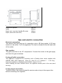
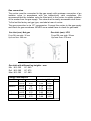
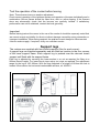
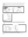
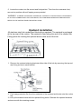
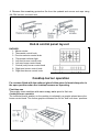
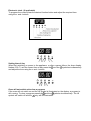
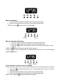
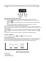
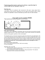
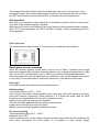
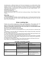
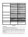
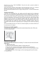
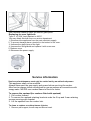
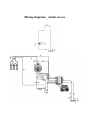
INSTALLATION INSTRUCTIONS
USER INSTRUCTIONS
COOKER MODEL
VEF90EG
90X60 cm
Important information
Introducing your new cooker
We thank you and congratulate you on your choice.
These instructions cover four cooker models:
Dear Customer,
Congratulations on purchasing your new product from Think Appliances.
To register your parts and labour warranty (some conditions apply please refer to your
warranty card for more details) please contact out Customer Care team on:
1800 444 357
Our Customer Care centre is there to ensure you get the most out of your appliance. For
example, should you want to learn more about recommended cooking temperatures, the
various cooking functions available, how to set and program your LED clock, and importantly
taking care of your appliance when cleaning, please call us because we are here to help you.
It is important that you read through the following use and care manual thoroughly to
familiarize yourself with the installation and operation requirements of your appliance to
ensure optimum performance.
We also carry a complete range of spare parts for all Think products. For all your spare parts
enquiries please contact our team at Pronto Parts on:
1300 306 973
Again, thank you for choosing an appliance brought to you by Think Appliances and we look
forward to being of service to you.
Kind regards
Management
Think Appliances
These carefully designed products, manufactured with the highest quality materials, have
been corefully tested to satisfy all your cooking demands.
We therefore request that you read and follow these easy instructions which will allow you
to obtain excellent results right from the start.
AlI cookers feature a gas hotplate containing 5 cooktop burners, including one centrai wok
burner, and the multi-function ovens.
The cooker's data plate is accessible even with the cooker fully installed. It is positioned
on the inside of the oven door, centre bottom. A copy of the data plate is also reproduced
on last page of this booklet. Always quote the details from it to identify the appliance when
ordering spare parts or requesting a service.
Notes on disposal
Old appliances still have some residual value. An environmentally friendly method of
disposal will ensure that valuable raw materials con be recovered and used again.
Before you dispose of your old appliance, make sure that it has been rendered inoperable.
Your new cooker was protected by suitable packaging while it was on its way to you. All
materials used for this purpose are environmentally friendly and suitable for recyding.
Please make a contribution to protecting the environment by disposing of the packaging
appropriately.
Do not spray aerosols in vicinity of this appliance while it is operation.
Where this appliance is installed in a marine environment or in caravans,
for safety reasons it shall not be used as a space heater.
This appliance is unsuitable for installation in marine craft, caravans or
mobile homes, unless each burner is fitted with a flame safeguard.
DO NOT MODIFY THIS APPLIANCE
DO NOT USE OR STORE FLAMMABLE MATERIALS NEAR THIS APPLIANCE.
This appliance is not intended for use by persons (including children) with
reduced physical, sensory or mental capabilities, or lack of experience and
knowledge, unless they have been given supervision or instruction
concerning use of the appliance by a person responsible for their safely.
Children should be supervised to ensure that they so not play with the
appliance.
Warning: Accessible parts will become hot when in use. To avoid burns or
scalds children should be kept away.
Warning: In order to prevent accidental tipping of the appliance, for
example by a child climbing onto the oven door, the stabilising means
must be installed. Refer to the instructions for installation.
Before connecting your new cooker
Before using your new cooker, please read these 'Instructions for Use' carefully. They
contain important information concerning your personal safety as well as on use and care
of the oven.
Please keep the operating and installation instructions in a safe place; this important
documentation may also be of use to a possible subsequent owner.
Do not use the cooker if it is damaged in any way.
Installation and connection of the cooker should be performed according to the
instructions and connection diagram provided, and should be entrusted to a licensed
specialist. In the event of a damage that occurs as a result of improper connection, the
warranty will be void.
Our appliances meet the applicable safety regulations for electrical appliances, Repairs
may be performed only by authorised persons. Inexpert repairs may entail serious injury to
you, the user
Safety considerations
Never leave the appliance unattended when cooking with fat or oil. It could ignite if
overheated.
In case of a defect, switch off at the mains.
Do not dean the oven with steam or high pressure cleaners
Ensure that the power cord does not get caught in the hot oven door. The plastic
insulation could melt.
Do not use loose greaseproof paper in the oven (e.g. when heating the oven). The paper
could be drawn to the fan and damage the fan and the element
Do not insert a baking sheet or aluminium foil sheet at the bottom of the oven. A heat
build-up could result and cooking times and temperatures could change or enamel could
be damaged.
Do not pour water on the hot oven floor. Damage to enamel could result
Always piace a baking tray below a roast to prevent juices from dripping on the oven lining
Do not place heavy items on the oven door when open as this may result in damage to the
door hinges
To ensure correct cooking the oven door must dose properly.
Keep the door sealing surfaces clean at all times
Statutory regulations
Installation instructions
This appliance shall be installed in accordance with the manufacturer's installation
instructions, local gas fitting regulations, municipal building codes, electrical wiring
regulations, AS 5601 the Australian Standard for gas installations. Refer also to AS 5601
for pipe sizing tables
Gas supply
Check that the data plate shows the appliance is suitable for the available gas supply. The
data plate is located on the inside of the oven door, centre bottom. A copy of the data
plates is reproduced on the last page of this booklet.
Electrical supply
All models require connection to a 15 Amp wall socket
Instructions
1. The model number and the type of appliance, gas pressure and gas type ore found on
the inside of the oven door, centre bottom. A copy of the data plates is reproduced
on the last page of this booklet.
2. The appliance requires connection to a 240 V,50 Hz electric supply. The power point
must be installed by an authorized person.
3. Before commencing any work, make sure that the power point switches ore turned off
and the three in plug is removed
4. If the appliance cannot be adjusted to perform correctly contact your local gas utility.
5. Instruct the user in the operation of the appliance before leaving.
Vertical clearances:
The cooker shall be installed so that a vertical clearance of at least 600 mm is maintained
between its burners and any combustible material, and where this is not practicable, the
underside of an combustible material less than 600 mm above the burner shall be
protected by noncombustible millboard at least 6 mm thick which is covered with sheet
metal not less than 0.4 mm thick, or shall be protected by an equivalent material,
extending at least 225 mm beyond the sides of the cooker.
Overhead clearances:
Range hoods and exhaust fans shall be installed in accordance with the manufacturer's
instructions. However, in no case shall the clearance between the top of the highest burner
of the cooking appliance and the underside of a range hood be less than 600mm, or an
overhead exhaust fan, 750 mm
Side clearances to vertical surface:
If the distance measured from the periphery of the nearest burner to any vertical
combustible surface, is less than 200 mm, the surface shall be protected in accordance
with clause 5.12.1.1 and 5.12.1.2 of A5 5601.
Installation
Make sure the minimum clearances to combustible materials are maintained during the
installation including adequate space for the operation and servicing of the cooker. For
height limitations use the dimensions as shown in the drawing.
Overall dimensions (with legs adiusted to 180mm).
Height over hob:
910 mm
Height over upstand:
980 mm
Width:
895mm
Depth: (incl. oven door handle & knobs):
660mm
Depth: (flush with oven door):
610mm
Gas and electric connection
Electrical connection
The electric lead and plug are for connection onto a 15 Amp socket. A 15 Amp
socket is to be within 1 m of the appliance.The lead is situated at the left hand side
of the cooker.
Gas regulator
The gas connection is via 1/2" compression. Connect the cooker to the gas supply
and check for gas soundness
If using a flexible connection
This appliance is approved for connection with a Flexible Hose, which complies with
AS/NZS 1869 (AGA Approved), 10mm ID, class B or D, between 1 - 1.2m long .
Connection shall be in compliance with AS 5601, clause 5.12.1.8
When installing the hose restraint device, the appliance anchor point is the rear panel
securing.
If using copper connection
To allow cooker to be moved forward for service make a loop in the copper tube
before connecting onto regulator.
Gas connection
The cooker must be connected to the gas supply with upstream connection of an
isolation valve in accordance with the respectively valid requlations. We
recommend that the isolation valve be fitted prior to the cooker to enable isolation
of the cooker from the gas supply. The valve must be easily accessable at all times
To find out the factory set gps type, see label at rear of cooker
The gas connection is via 1/2" compression. Connect the cooker to the gas supply
and check for gas soundness. NEVER use a naked flame to check for gas leaks.
Gas inlet (mm)- Nat gas
Gas inlet (mm)- LPG
From RH rear side: 35mm
Up from floor: 675 mm
From RH rear side: 35 mm
Up from floor: 590 mm
Gas inlet with different leg heights – mm
Min NG: 560
LP: 645
Ref NG: 590
LP: 675
Max NG: 595
LP: 680
Energy consumption
Burners
Gas type
Small
Natural
U-LPG
Natural
U-LPG
Natural
U-LPG
Natural
U-LPG
Medium
large
Wok
Oven/Grill
(mm)
0.90
0.54
1.18
0.70
1.55
0.92
1.65
0.98
Pressure (kPa) Injector
1.0
2.75
1.0
2.75
1.0
2.75
1.0
2.75
Mj/hr
4.00
3.75
7.12
6.20
12.5
11.25
13.0
13.0
Watts
3000 W
Test the operation of the cooker before leaving
Note: These burners have no aeration adjustment
Check correct operation of the ignitions system and operation of burners individually and in
combination. Burner flames should be clear blue, with no yellow tipping. If the burners
show any abnormality check that the burners are correctly located. If satisfactory
performance can not be obtained, contact the local gas utility.
Important
Before leaving instruct the owner in the use of the cooker it should be expressly noted that
we cannot accept any liability for direct or indirect damage caused by wrong connection or
improper installation. When being repaired, the appliance must always be disconnected
from the mains supply; if required, notify our customer service
Support legs
The cookers ore supplied with four transit supports.(One for each corner).
4 support legs ore supplied separately and are fitted on location to the four corners
of the lower support frame. Each support leg is pushed over the relevant transit
support until flush with the support frame.
Each leg is adjusted by screwing the lower section in or out as required for fitting to a
900mm bench height. For lower bench tops a djust the height as required.The adjustment
range for the leg is 150-185mm. With the legs adjusted to a height of 180mm the hob is
located 10mm above the horizontal combustable surface, ref. AS5601
If the legs are not used and the cooker is mounted onto a plinth, fit transit legs to allow for
clearance.
Once legs are adjusted to a nominai cooker height of 91 Omm, fit the antitilt restraint
bracket.
1. Fit flat strap to rear of cooker at the centre point on lower edge using supplied screw
2. Mark centre position of the cooker installed position on floor
3. Measure from rear most point hob to mount point of strap. (Dimension A), then using
Dimension A mark back edge of the bracket on centre line. Use bracket to mark fixing
point.
4. Fix restraint bracket to floor at position marked. Use suitable fixing.
Note: For concrete floor, use anchor provided. For other construction use a suitable
fastener.
5. Locate the cooker into the correct and final position. Then from the underside front,
secure into position with self tapping screw provided.
WARNING - IN ORDER TO PREVENT ACCIDENTAL TIPPING OF THE APPLIANCE, FOR EXAMPLE
BY A CHILD CLIMBING ONTO THE OVEN DOOR, THE STABILISING MEANS MUST BE INSTALLED.
REFER TO THE INSTRUCTIONS FOR INSTALLATION
Upstand installation
All stainless steel hob models are fitted with an upstand. The upstand is packaged
at the top rear of the cooker. The upstand is fixed along the rear of the cooker hob.
Fixing points for locating the upstand are at either end of the hob
1. Remove the upstand retaining brackets either side of the hob by removing the top and
rear fixing screws in each bracket
2. Peel away protective film from the underside of the upstand and locate onto the cooker
top.
3. Line up the bracket holes with the upstand fixing holes. Relocate the upstand brackets
and secure with the retaining screws.
4. Remove the remaining protective film from the upstand and secure end caps using
M4 CSK screws, one each end.
Hob & control panel lay-out
DAF90EG
1. Minute minder
2. Thermostat control knob
3. Function selector control knob
4. Thermostat indicator light
5. Left front burner control knob
6. Left rear burner control knob
7. Central (wok) burner control knob
8. Right rear burner control knob
9. Right front burner control knob
Cooktop burner operation
For cookers fitted with the optional glass lid the glass lid must always be in
the open position when the cooktop burners are operating.
First time use
Thoroughly clean cooktop with warm soapy water prior to first use.
Cooktop burner operation
The individual burner position on the cooktop is indicated by a graphic placed above the
burner control knob. Two further graphics indicated the 'full on' and 'turn down ' positions.
Ignition
1. To operate the individual cooktop burners depress the appropriate control knob and
turn anti-clockwise to the spark symbol. Push to activate the electronic ignition.
2. Once flame is established turn the knob to the desired setting.
3. If the flame goes out repeat the procedure.
NOTE: if the burner does not ignite within 5 seconds, wait 5 minutes before reigniting.
Cooktop burner adiustments
The control knob is used to adjust the flame of the gas burner.
'High flame' graphic = highest output
'low flame' graphic = lowest output
Use 'High flame' setting to bring the pan to the boil, then adjust the flame to maintain the
required pan temperature. Burner flames should be clear blue, with no yellow tipping. If the
burners show any abnormality check that the burner heads are correctly located. lf
satisfactory performance cannot be abtained after consulting the trouble shooting guide,
contact the authorised service provider. Please state the cooker model number to the
service agent. The model number is stated on the data plate. The data plate is located on
the inside of the oven door, centre bottom. A copy of the data plate is also repro duced on
the last page of this booklet
Ventilation
The use of gas burners leads to the production of heat and moisture in the kitchen. For this
reason make sure that the room is properly ventilated. Keep ventilatin openings, such as
windows, open or provide a mecnanical ventilation device (e.g. a range hood of overhead
exhaust fan)
Minute minder ((if applicable)
The minute minder control knob is positioned on the left hand side of the control panel. To
activate the timer, rotate the knob clock-wise through 360°, then return the knob anticlockwise to required cooking time
Electronic clock (if applicable)
To program the cooker press the desired function button and adjust the required time
using the + and - buttons
Setting time of day
When first switching on power to the appliance, or after a power failure, the timer display
symbols simultaneously
flashes 0.00. To set the correct time of day press the and the
and adjust the time using the + and - buttons
Oven will not switch on/to clear a program
If the oven will not switch on and the 'A' symbol is illuminated on the display, a program is
stili running. To clear a program press the
and the symbols simultaneously. The 'A'
symbol will switch off and the
only will be illuminated.
Manual operation
1. T urn the function selector control knob to the required mode.
2. Then turn thermostat control knob to the desired temperature.
NOTE: only the
symbol should be illuminated
Manual operation with timer
1. Turn the function selector control knob to the required mode.
2. Then turn thermostat control knob to the desired temperature.
3. Press the
symbol and adjust the required cooking time using the + and –
buttons.
and the 'A' symbols should be illuminated.
NOTE: the
At the completion of the cooking time an audible signal will sound. To turn off the signal
press the symbol.
Semi automatic operation with end cooking.
In this mode the oven will turn itself oH when the preset end of cooking time is reached.
1. Press the
symbol and using the + and - buttons adjust the ti me you wish the
cooking to stop
2. Turn the function selector control knob to the required mode.
3. Then turn thermostat control knob to the desired temperature.
NOTE: the 'A' and the
symbol should be illuminated.
At the conclusion of the cooking time the signal will sound and the 'A' symbol will flash.
will turn off and the oven will also turn off. To stop the signal press the
button.
The
Automatic operation with end cooking
In this mode the oven is programmed to start and stop at a predetermined time.
1. Press the symbol and using the + and - buttons adjust the time you wish the
cooking to stop.
2. Press the
symbol and adjusting the + and - buttons adjust the cooking duration
time.
3. Turn the function selector control knob to the required mode 4. Then turn
thermostat control knob to the desired temperature.
NOTE: The oven will turn on at the 'end of cooking' time minus the 'duration of cooking
time'. If the start of the cooking time is still ahead of the current time the 'A' symbol only will
be illuminated.
At the conclusion of the 'end of cooking time' the signal will sound and the 'A' symbol will
will turn off and the oven will also turn off. To stop the signal press the
flash. The
button.
'The time to run' can be verified at any time by pressing the appropriate button.
To clear a program
To clear a program press the
and the
symbols simultaneously.
Use of cooktop burners
For safety and economie gas usage you should always use the correct pan on the correct
burner. Flames should not protrude beyond the base of the pan. You will save energy,
time and money by always placing the correct pan size on the correct gas ring
Oven /grill operation
Accessories
1 wire shelves
1 enamel baking tray
Foods being grilled must be monitored at ali times, especilally high fat
content foods such as sausages, chops, ek.
First time use
Thoroughly clean the appliance and accessories with warm soapy water before
using them for the first time. Operate the oven for about 30 minutes at 200°C on fan
forced or fan assisted in order to eliminate any odours from all oven elements.
Oven /grill use for model LIF90EG
Thermostat and function selector control knobs
Oven heat distribution
The electric oven is heated by 2 elements; one the roof of the oven and one circular
element around the fan. The function selector control knob controls the elements
relative to the graphic symbols on the control panel.
The elements cycle on and off as required to reach and maintain the set temperature. The
oven and grill functions are both contained within the one oven compartment and can be
used in conventional mode or with the fan. In order to operate the grill or the oven, both
the thermostat control knob and the function selector control knob must be activated.
Turning only one control knob will not have any effect on the oven except to turn on the
oven light or the electric fan. The thermostat controls the oven at settings up to 250°C.
Oven functions
Grill heating element (radiant grill)
Rear circular heating element with fan. (fan forced cooking)
Fan on only (defrost)
Switching the oven ON
1.
2.
Turn the function selector control to the required cooking mode. The orange 'power
on' thermostat indicator light illuminates.
Set the temperature control to the required cooking temperature. The selected
temperature will be maintained automatically
The orange thermostat indicator light illuminates when the oven is first turned on, and
extinguishes when the required temperature is reached. The indicator light will cycle ON
and OFF as the element cycles ON and OFF to maintain the oven temperature
Grill operation
Note: due to the operation of the cooling fan, all methods of grilling in this oven require the
oven door to be closed during grill operation.
When the grill is used in the following 'fan forced' mode set the thermostat knob no higher
than 175°C, which is between the 150°C and 200°C setting, to avoid overheating the front
of the appliance.
Shelf positions
The oven features 5 shelf positions. The levels are counted from top to bottom.
Description of oven functions
When the function selector control knob is set to one of these 3 positions the orange
thermostat indicator light activates, indicating that the oven is being energised and the light
turns on and off as the elements cycle on and off to maintain the required temperature.
Personal experience will help determine any variations in the values reported in the table.
In any case, it is recommended to follow the instructions of the specific recipe used.
Oven light
Oven light will also be activated on all cooking functions
Radiant grilling
Thermostat setting from 50°C – 175°C
These modes use radiant heat provided by the centre part of the grill element and centre
plus outer element respectively. Shelf positions 2 or 3 should be used. Ideal for quick
browning of small quantities of food such as cheese on toast.
Always use the grill pan and wire grid together
Turn the food after approximately two thirds of cooking time
Lightly brush food with oil to avoid it sticking
Always monitor food being grilled in these two modes
Fan forced cooking
Thermostat setting from 50°C – 250°C
Moderate oven 170°C
In this mode the rear circular heating element provides heat whilst the fan distributes the
heat evenly throughout the oven interior. It is possible to cook several dishes
simultaneously on different shelves and food can be placed on any shelf position. Meat
cooked in fan forced mode will brown on all sides, eliminating the need for a separate
rotisserie function. It is particularly suitable for roasting cuts of meat weighing more than
150g. Place meat on the wire grid in the universal pan and roast at approximately 170°C.
Aavantages of this mode are:
Shorter pre-heating time
Cooking with lower temperatures
Shorter cooking times ideal for all multi-Ievel cooking including: Bread, Roasts, Cakes,
Pastries
Defrosting
Thermostat setting 0°C
In this mode the fan circulates cold air inside the oven. In this way frozen food can
be evenly defrosted. For best results when defrosting piace the food on the wire
rack in the universal pan
Oven cooking tips
Preheat oven until the temperature indicator light extinguishes. (The indicator light will
cycle on and off as the element cycles on and off to maintain the oven temperature).
Refer to cooking chart for shelf positions. Personal experience will help determine any
variations in the positions reported in the chart. In any case, it is recommended to follow
the instructions of the specific recipe used.
Open door as little as possible during operation
When opening the oven door during operation turn to a non fan function to minimise heat
loss
If necessary to cover food with foil or baking paper whilst cooking in fan mode, ensure that
the foil or paper is firmly secured.
For easy viewing and a more even cooking result bring the dishes and trays forward to the
front of the oven shelf. Avoid placing food too dose to rear of oven.
For even heat circulation ensure that dishes and trays do not touch each other or the sides
of the oven. Best results when baking, roasting and multi level cooking will be obtained by
cooking with the fan in operation
Do not place foil, baking trays, dishes or any other items directly on the base of the oven
Note: When oven is operating the glass door will become hot
Problem
Burners don’t light
Cooktop burner difficult to light
Trouble shooting guide
Possible cause
Action
Power to appliance turned off
Burner cap
positioned
damp
or
Turn on power supply
incorrectly Dry and reposition cap
Spark ignitor clogged with grease
Burner ports blocked
Clean ignitor
Spark igniter does not function
Clean ports
Phone service number for service or
advice
Grill element/browner smoking
when on
Top of oven compartment soiled
Clean top of oven compartment
Food is not cooking to expectation
User may still be using settings of
Check cooking chart - consumer
will become familiar with use
If problem persists phone service
number for advice
previous cooker - all ovens have
different characteristics
Food cooking too quickly
Food taking too long to cook
Oven temperature set too high
Check oven chart, Iower
temperature
Pan used larger than recipe required
Allow less time or use smaller pas
Thermostat too high - faulty
Phone service number for service
or advice
Opening oven door too frequently Avoid opening door and minimise
time open
or far too long
Oven not preheated sufficiently
Allow to preheat, especially far
high temperature cooking
Temperature set too Iow
Food is cooking unevenly
Cakes not cooked through to centre
Food pale on top
Cake cracking on top
Minute minder does not ring
Cleaning hob
Check chart and / or raise
temperature
Food was chilled or partially frozen Allow to thaw completely or allow
Ionger time for cooking
Heat loss from oven
Phone service number for service
or advice
Thermostat too Iow - faulty
Phone service number for service
or advice
Tray or pan pushed too far to the
Allow 5 cm airflow all around Use
back or sides of oven
fan setting
Tray too large
Use smaller tray
Tray or oven overloaded
Reduced items on tray or number
of trays in oven
Oven temperature too hight
Reduce temperature slightly
Temperature too high
Reduce temperature
Oven overloaded
Cook fewer items
Incorrect shelf position
Check cooking chart
Raise temperature - refer to chart
Increase cooking time
Temperature too Iow
Insufficient cooking time
Sides too high on cake tin
Incorrect position
Tray too large
Oven too hot
Use smaller tin
Batter too th ick
Check recipe or add more liquid
Control knob has not been sufficiently
wound up
Even if setting for a short time it is
recommended to wind the knob
through 360° (to 60 mins) then turn
back to the required time
Refer to cooking chart
Allow 5 cm airflow around items
Reduce temperature
Cleaning
Once the appliance is cold, clean it with a sponge and soapy water. Remove any spills
immediately. This will avoid unnecessary effort later
Allow burners and trivets to cool down before cleaning them.
The burners and trivets must be cleaned regularly to keep them in good condition. This is
done by submerging them in soapy water and scrubbing them with a non-metal brush to
keep the ports and slots free from obstructions so they give a perfect flame. Dry the burner
caps and trivets whenever wet or damp. Do not wash the burner caps and trivets in a
dishwasher.
After cleaning and drying ensure that the burner heads and caps are replaced correctly on
the burner body
For cookers fitted with a stainless steel hob the high temperatures generated by using
the wok burner may cause the stainless steel hob of your hotplate to become
discoloured over time. THIS IS NORMAL. Clean the hob with a product suitable for
cleaning stainless steel
Never use abrasive products, sharp objects, steel scouring pads, knives, etc., to remove
stubborn food remains from the hob surface, trivets, burners and oven interior
Do not allow acidic products such as vi negar, lemon juice etc., to come into contact with
the hob
Cleaning oven interior
Clean the oven enamelled floor, wire shelves and shelf supports with hot detergent
suds. This oven is fitted with self cleaning linings on the roof, sides and back of the oven.
The liners are covered with a special micro-porous enamel that absorbs and removes fat
residue during baking. Should any liquid fat splatter onto the liners, self cleaning action
may not be adequate. In this case the liners may be wiped with a damp sponge. Mild
detergent may be used but no chemical cleaners. After this, heat the oven to the
maximum temperature for a period of 30 minutes. If the stains persist wait until the oven
has cooled down and repeat the above precedure. Important: always clean the
enamelled surfaces and wire components prior to starting the 30 minute heat cleaning
cycle.
It is recommended that the oven interior be cleaned regularly as excessive build-up of
fat can become a fire hazard.
Cleaning oven shelf supports
To remove the shelf supports remove the knurled knobs either side, lift the wire
rack and swing forwards
Cleaning oven glass door
The oven door may be removed for cleaning. To remove the oven door follow the
steps below:
1. Open the door fully
2. Lift the two levers forward as shown in figure below left
3. Close the door as far as the first stop (created by the raised levers).
4. Lift the door upwards and outwards to remove it from its mounting as shown
in figure below right.
5. To replace the door, fit the hinges on their mountings and lower the levers
6. Close the door.
Use a window cleaner to clean the exterior glass panel.
Replacing the oven light bulb
Type: E 14, 25W, heat resistant to 300°C.
You may obtain this bulb from our service department
1. Disconnect the appliance from the main electricity supply.
2. To prevent damage place a teacloth in the bottom of the oven.
3. Unscrew the glass cover of the light.
4. Unscrew the old lightbulb and replace it with a new one.
5. Replace cover
6. Reconnect the power supply.
Service information
Service and maintenance must only be carried out by an authorised person
This appliance shall not be modified.
Always disconnect the gas supply and power before servicing the cooker.
After service always check connections for gas soundness at connections with
soapy water. NEVER use a naked flame to check for leaks.
To remove the upstand (for cookers fitted with upstand)
1. Pull cooker forward
2. To remove the upstand retaining brackets undo the 2 top and 2 rear retaining
screws securing each bracket.
2. Lift the upstand from the cooker hob.
To clean or replace a cooktop burner injector
1. Remove pan support, burner cap and burner head.
2. Using a 7mm socket spanner unscrew and clean or replace the cooktop burner's
injector.
3. Replace burner head, cap and pan support. Ensure that the burner head and cap are
in the correct position.
Access to the under hob area
Pull cooker forwards to gain access to the rear of the cooker
1. Remove upstand
2. Remove pan supports, burner caps and burner heads
3. Using a torx T20 head driver remove the screws securing the burners to the hob. 2
per boiling burner and 4 for the wok burner.
4. Remove the lower 2 screws of each upstand bracket
5. lift hob at rear and slide out of position.
Wiring diagrams model VEF90EG
A copy of those diagrams is situated on the back panel of the cooker.
Data plates
The data plates reproduced below cover all three cookers. You will find your particular
model number on the data plate attached to the inside of the oven door, centre bottom.
Always quote your model number when requesting a service calI.
note:
Refer to cover page for duplicate data label applicable to your appliance.
310436