1
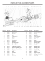
ADVANTAGE
POOL PUMPS
SP1 OWNER’S MANUAL
INSTALLATION, OPERATION & PARTS
To prevent potential injury and to avoid unnecessary service calls, read this manual
carefully and completely.
CAUTION – We highly recommend a qualified professional install and
service this product.
WARNING – This manual contains important safety information that must
be furnished to the end user of this product. FAILURE TO READ AND
FOLLOW ALL INSTRUCTIONS COULD RESULT IN SERIOUS INJURY.
SAVE THIS INSTRUCTION MANUAL
624 South B Street • Tustin, CA 92780
Toll Free: 800.636.8866 • Tel: 714.505.1166 • Fax: 714.505.1160
advantageman.com
PRODUCT REGISTRATION
(Retain For Your Records)
DATE OF INSTALLATION
ADVANTAGE
POOL PUMPS
__________________________________________
INITIAL PRESSURE GAUGE READING (CLEAN FILTER) ________________
PUMP MODEL _____________________ HORSEPOWER ________________
FILTER MODEL ____________________________________________________
IMPORTANT SAFETY INSTRUCTIONS
When installing and using this electrical equipment, basic safety precautions should always be
followed, including the following: Failure to follow instructions may result in injury.
READ AND FOLLOW ALL INSTRUCTIONS
IN THIS OWNER’S MANUAL
AND ON EQUIPMENT.
KEEP SAFETY LABELS IN GOOD CONDITION
AND REPLACE IF MISSING OR DAMAGED.
WARNING – To reduce risk of injury, do not permit children to use or climb on this product. The
ANSI/NSPI 4 Standard (above-ground and on-ground pools) advises that components such as the filtration
system, pumps, and heaters be to prevent their being used as a means of access to the pool by young children.
Closely supervise children at all times.
CAUTION – The Advantage Filter System is intended for use on permanently installed above-
ground swimming pools and may also be used with hot tubs and spas if so marked. Do NOT use with storable
pools. A permanently installed pool is constructed in or on the ground or in a building such that it cannot be
readily disassembled for storage. A storable pool is constructed so that it is capable of being readily
disassembled for storage and reassembled to its original integrity.
Though this product is designed for outdoor use, it is strongly advised to protect the electrical components
from the weather. Select a well-drained area, one that will not flood when it rains. It requires free circulation
of air for cooling. Do not install in a damp or non-ventilated location.
Bond motor to pool structure. Use a solid copper conductor, size or larger. Run wire from external bonding
lug to reinforcing rod or mesh. Connect a No.8 A WG (8.4 mm2) solid copper bonding wire to the pressure
wire connector provided on the motor housing and to all metal parts of swimming pool, spa, or hot tub, and to
all electrical equipment, metal piping or conduit within 5 ft. (1.5 m) of inside walls of swimming pool, spa, or
hot tub. (In Canada use No.6 A WG bonding wire.)
2
IMPORTANT SAFETY INSTRUCTIONS
NOTE: The National Electrical Code (NEC) permits use of a cord with a maximum 3 ft. (1 m) length. If your
pump is equipped with a cord complying with the NEC, the following three (3) items apply.
WARNING
WARNING –Risk of Electric Shock. Connect only to a grounding type receptacle
protected by a Ground Fault Circuit Interrupter (GFCI). Contact a qualified electrician if you
cannot verify that the receptacle is protected by a GFCI.
WARNING – To reduce the risk of electric shock replace damaged cord immediately.
Do NOT bury cord. Locate cord to minimize abuse from lawn mowers, hedge trimmers and other equipment.
WARNING – To reduce the risk of electric shock, do NOT use an extension cord to connect unit
to electric supply. Provide a properly located outlet. Qualified personnel MUST do all electrical wiring.
CAUTION – All suction and discharge valves MUST be OPEN when starting the
filter system. Failure to do so could result in severe personal injury and/or property damage. All
drains and suction covers MUST have properly installed covers securely attached with the screws
supplied with the covers. If screws are lost, order replacement parts from your supplier.
DANGER – Suction Entrapment Hazard. Never use the pool or spa if a drain cover is damaged,
cracked, missing, or not securely attached. Suction in drains and suction outlets can cause drowning,
disembowelment, hair or body entrapment, severe injury, and death. Disembowelment, entrapment, or
drowning is possible when body parts or hair come in contact with damaged, broken, cracked, missing, or
unsecured drain covers and suction outlets. Suction from pumps with only one drain or suction outlet can
cause disembowelment, entrapment, or drowning. Pumps for pools and spas require two (2) functioning suction
outlets at least three (3) feet apart, on two (2) walls or on the floor and one (1) wall of the pool or spa. Installation
of pump and suction outlets must be in compliance with all applicable local building codes. Replace damaged,
broken, cracked, missing, or unsecured drain covers and suction outlets immediately.
WARNING – Hazardous Pressure. Pumps, filters, and other equipment/components of a swimming
pool filtration system operate under pressure. Incorrectly installed and/or improperly tested filtration equipment
and/or components may fail resulting in injury and/or property damage. A qualified pool professional MUST
conduct all pressure tests.
This product is intended for above-ground/on-ground swimming pool applications only. Do NOT connect to
a high-pressure system such as a municipal water main. To prevent explosion caused by entrapped air in the
filtration system use provided air relief valve to bleed air from the system. Confirm that ALL filtration system
component clamps, bolts, and covers have been tightened to the manufacturer's recommendations.
WARNING – Never operate or test the filtration system at more than 30 PSI.
SAVE THESE INSTRUCTIONS
3
PUMP SAFETY INSTRUCTIONS
When installing and using this electrical equipment, basic safety precautions should always be followed,
including the following:
1. READ AND FOLLOW ALL INSTRUCTIONS.
2. WARNING – To reduce the risk of injury, do not permit children to use this product unless they are
closely supervised at all times.
3. WARNING – Risk of Electrical Shock. Connect only to a grounding type receptacle protected by a
ground-fault circuit-interrupter (GFCI). Contact a qualified electrician if you cannot verify that the
receptacle is protected by a GFCI.
4. Do not bury the electrical cord. Locate the cord to minimize the abuse from lawn mowers, hedge
trimmers, and other equipment.
5. WARNING – To reduce the risk of electrical shock, replace damaged cords immediately.
6. WARNING – To reduce the risk of electrical shock, do not use an extension cord to connect unit to
electric supply; provide a properly located outlet.
7. CAUTION – For continued protection against possible electrical shock, this unit is to be mounted
to the base in accordance with the installation instructions.
8. SAVE THESE INSTRUCTIONS.
WARNING
THIS FILTER OPERATES UNDER HIGH PRESSURE. WHEN ANY PART OF THE
CIRCULATING SYSTEM (e.g. LOCK RING, PUMP, FILTER VALVES, ETC.) IS
SERVICED, AIR CAN ENTER THE SYSTEM AND BECOME PRESSURIZED.
PRESSURIZED AIR CAN CAUSE THE LID TO BE BLOWN OFF WHICH CAN
RESULT IN SEVERE INJURY, DEATH, OR PROPERTY DAMAGE. TO AVOID THIS
POTENTIAL HAZARD, FOLLOW THESE INSTRUCTIONS.
1. BEFORE REPOSITIONING VALVES AND BEFORE BEGINNING THE ASSEMBLY,
DISASSEMBLY, OR ADJUSTMENT OF THE LOCK RING OR ANY OTHER SERVICE OF
THE CIRCULATING SYSTEM: (A) TURN THE PUMP OFF AND SHUT OFF ANY
AUTOMATIC CONTROLS TO ENSURE THE SYSTEM IS NOT INADVERTENTLY STARTED
DURING THE SERVICING; (B) OPEN AIR RELIEF VALVE; (C) WAIT UNTIL ALL PRESSURE
IS RELIEVED.
2. WHENEVER INSTALLING THE FILTER LOCK RING FOLLOW THE CLEANING FILTER
INSTRUCTIONS EXACTLY.
3. ONCE SERVICE OF THE CIRCULATING SYSTEM IS COMPLETE FOLLOW THE INITIAL
START SYSTEM RESTART INSTRUCTIONS EXACTLY.
4. MAINTAIN CIRCULATION SYSTEM PROPERLY. REPLACE WORN OR DAMAGED PARTS
IMMEDIATELY (e.g., lock ring, pressure gauge, relief valve, o-rings, etc).
5. BE SURE THAT THE FILTER IS PROPERLY MOUNTED AND POSITIONED ACCORDING
TO THE INSTRUCTIONS PROVIDED.
4
FILTRATION
WARNING
To reduce the risk of electrical shock, only connect to a GFCI protected receptacle. Failure
to do so could result in an electrical shock to pool users, installers, or others, which can
result in serious personal injury or death.
Your cartridge filter is designed to produce clear, sparkling water and operate for years with
a minimum of maintenance when installed, operated and maintained in accordance with
these instructions.
A. YOUR FILTER USES A CARTRIDGE ELEMENT TO REMOVE DIRT PARTICLES FROM THE
WATER.
1. Dirt is collected in the filter by the cartridge element as water flows through the filter. Water enters
the filter through the filter inlet port and is distributed evenly through the cartridge element.
2. The dirt is removed by the cartridge fabric and the clean water flows through the filter outlet port
and is returned to the pool through the piping or hoses.
B. AFTER A PERIOD OF TIME, DIRT WILL ACCUMULATE IN THE FILTER CAUSING A
RESISTANCE TO THE FLOW OF WATER THROUGH THE FILTER.
1. This resistance results in a diminished flow of water and a rise in the filter pressure. Eventually the
filter will have removed so much dirt and the filter pressure risen to such a point that it will be
necessary to clean your filter,
2. The filter’s function is to remove suspended matter from the water and does not sanitize the water.
For sparkling clear water, the water must be sanitized and as well as balanced.
3. Pool chemistry is a specialized area, and you should consult your local pool service specialist for
specific details. In general, proper pool sanitation requires a free chlorine level of 1 to 2 PPM and a
PH range of 7.2 to 7.6.
WARNING
Failure to operate your filter system or inadequate filtration can cause poor water clarity obstructing visibility
in your pool. Pool water clarity may obscure objects in the water, which while swimming and diving could
cause severe personal injury and death. Never swim in a pool with poor water clarity.
READ AND FOLLOW ALL SAFETY INSTRUCTIONS
5
INSTALLATION INSTRUCTIONS
1. Carefully remove the equipment from the carton and check for any evidence of damage due to rough
handling or shipping. If any of the equipment is damage, immediately notify the company where the
equipment was purchased.
2. This pump and filter comes assembled to base from the carton. Be sure to position base of unit on flat
surface.
3. Install 1.5 inch barb X 1.5NPT fitting into the suction port of the pump (This fitting is provided in carton.)
Use Teflon tape on threaded section to be installed into pump. When applying Teflon tape to plastic threads,
wrap the entire threaded portion of the male fitting with two to four layers of tape. Wind the tape clockwise
as you face the open end of the fitting, beginning at the end of the fitting. Tighten fitting by hand then use
a tool to engage fitting an additional 1-1/2 turns. Do not over tighten fitting or you may cause damage.
4. Install provided pressure gauge in top of filter, be sure to use Teflon tape as described Above to avoid any
leaks.
5. Connect the pool suction plumbing from the skimmer to the inlet on the pump with the hose provided. Make
sure to attach with hose clamps on both skimmer as well as pump side of hose to avoid leakage or possible
failure. Tighten both clamps to ensure watertight connection.
6. Connect provided hose from outlet of filter to return on pool. Make sure to use hose clamps provided on
both pool side as well as filter connection of hose. Make sure to tighten both hoses clamps to ensure
watertight connection.
6
START-UP AND OPERATION
1. Be sure all connections have been made and are secure.
2. Make sure the hair and lint pot of the pump is filled with water. (FAILURE TO FILL THE HAIR AND
LINT POT WITH WATER WILL RESULT IN DAMAGE TO THE PUMP AND PUMP SEAL). Failure
to do so will void warranty.
3. OPEN THE MANUAL AIR RELIEF VALVE 1/2 TURN COUNTERCLOCKWISE TO RELEASE AIR.
4. STAND CLEAR OF THE FILTER. Start pump allowing the filter tank to fill with water. Close the high
flow air relief valve after a steady stream of water appears.
5. Your filter has now started its filter cycle. You should check that the water is returning to the pool and take
note of the operating pressure. My original starting pressure is ______________ PSI with the filter clean.
6. Check the system for water leaks. If a leak is found, shut off pump before correcting leak.
WARNING
THIS FILTER OPERATES UNDER HIGH PRESSURE. WHEN ANY PART OF THE
CIRCULATING SYSTEM (e.g. LOCK RING, PUMP, FILTER, VALVES, ETC.) IS
SERVICED, AIR CAN ENTER THE SYSTEM AND BECOME PRESSURIZED.
PRESSURIZED AIR CAN CAUSE THE LID TO BE BLOWN OFF WHICH CAN
RESULT IN SEVERE INJURY, DEATH, OR PROPERTY DAMAGE.
7. As the filter removes dirt and impurities from the pool water, the accumulation will cause the filter pressure
to rise and the flow to diminish. When the pressure gauge reading is 8 to 10 PSI higher than the clean filter
reading noted above, it is time to clean the filter’s element grids, see SECTION V. CLEANING THE FILTER.
SECTION V. CLEANING THE FILTER
1. Cleaning frequency will vary from pool to pool and with other factors such as weather conditions, heavy
rains, dust pollen, bather load and water chemistry.
a. Check the pressure gauge reading on a regular basis and when the pressure gauge reading increases
8 to 10 PSI over the initial clean filter reading, it is time to clean your CARTRIDGE ELEMENT.
2. Turn the pump off, shut off any automatic controls to assure that the system is not inadvertently started
during servicing.
3. Plug the skimmer port with a rag. This will prevent pool water from running out during servicing.
4. Open Air Relief Valve on top of Filter.
7
START-UP AND OPERATION
5. Remove the hair and lint strainer pot lid and clean the basket. Replace the basket and secure the lid.
6. Remove the filter lock ring by rotating the ring counter clockwise until the ring is free from the filter body.
7. Remove the filter lid using the lifting handles on the lid.
8. Remove the CARTRIDGE ELEMENT assembly from the filter body.
9. Using a garden hose, direct water spray at the CARTRIDGE ELEMENT to dislodge and wash away any
accumulated foreign matter and Diatomaceous Earth. Thoroughly clean the elements.
10. Clean and remove debris from the inside of the filter tank.
11. Replace the CARTRIDGE ELEMENT into the filter tank body. You will be able to feel the assemble drop
into and lock into place when in the proper position.
12. Clean any debris from the O-ring at the top of the filter tank. Apply a silicone lubricant to the O-ring. DO
NOT USE A PETROLEUM-BASE LUBRICANT ON THE O-RING. Failure to properly clean and
lubricate the a-ring may result in water leakage.
13. Replace the filter tank lid making sure it is fully and firmly seated on the tank body.
14. Place the filter lock ring over the filter lid, and turn clockwise until the lock ring hits the stops on the body.
DO NOT ATTEMPT TO OVER TIGHTEN.
WARNING
If the filter lock ring is damaged, replace it immediately. This filter operates under high
pressure. Replace locking ring if damaged or worn. Failure to replace locking ring can result
in the lid separating from the filter, which can cause severe injury or death.
15. Follow Initial Start Up and System Restart Instructions.
WARNING
Failure to operate your filter system or inadequate filtration can cause poor water clarity obstructing visibility
in your pool. Pool water clarity may obscure objects in the water, which while swimming and diving could
cause severe personal injury and death. Never swim in a pool with poor water clarity.
8
WINTERIZING
1. In areas that have freezing temperatures, the pool equipment must be winterized to protect it from damage.
2. With the equipment turned off, open the Relief Valve on top of Filter.
3. Allow the filter to drain completely.
4. Remove the drain port plugs on the pump and allow the pump to drain completely.
5. Drain all appropriate system piping.
6. It is recommended that the pump and filter be covered with a tarpaulin or plastic sheet to inhabit deterioration
from the weather.
DO NOT WRAP THE PUMP MOTOR IN PLASTIC.
7. Your filter is now winterized.
9
TROUBLESHOOTING
PROBLEM
CAUSE
REMEDY
Pool water not
sufficiently clean.
1. Pool chemistry not adequate to
inhabit algae growth.
Maintain pool chemistry or consult
pool service technician.
2. Inadequate turnover rate.
Run system for longer time or consult
dealer or pool service technician.
1. Insufficient cleaning of the
filter element.
Clean the filter element (see Cleaning
Filter instructions).
2. Restriction in plumbing.
Remove obstruction in return line.
1. Insufficient cleaning of the
filter element.
Clean the filter element (see Cleaning
Filter instructions).
2. Pool chemistry not adequate to
inhabit algae growth.
Maintain pool chemistry or consult pool
service technician.
3. Flow rate too high.
Restrict flow to capacity of filter.
1. Obstruction in the pump hair
and lint pot.
Clean basket in strainer.
2. Obstruction in pump.
Disassemble and clean pump.
3. Obstruction in suction line to pump.
Clean skimmer basket. Remove
obstruction in lines. Open valves in
suction line.
Higher filter
pressure.
Short filter
pressure.
Return flow to pool
diminished, low
filter pressure.
10
PUMP INSTRUCTIONS
WARNING
To reduce the risk of electrical shock, only connect to a GFCI protected receptacle.
Failure to do so could result in an electrical shock to pool users, installers, or others,
which can result in serious personal injury or death.
1. TO PRIME PUMP – (pump must be off).
a. Unscrew the lid from the pot and fill the pot with water to level of suction line. Inspect O-ring,
lubricate with silicone lubricant.
b. Tum the pump on; priming time will vary depending upon elevation above water level and horizontal
distance of suction line.
c. If the filter is installed, open the air relief valve, (before turning the pump on) until a steady stream
of water comes out, then close the air relief valve.
d. The pump is now primed. If the pump is installed below water level, close the return line prior to
filling the hair and lint pot with water. Line must be reopened before turning the pump on.
2. TO CLEAN THE BASKET – (pump must be off)
a. Follow the instructions above to prime the pump.
b. After removing the lid, remove the basket and empty the debris.
c. Replace the basket and proceed to fill the pot with water.
d. It is important to visually inspect the basket, through the see through lid, at least once a week. A
dirty basket will reduce the efficiency of your system, and can put an abnormal load on the pump,
which could result in costly repair bills.
3. SHAFT SEAL – (rotary seal). The shaft seal consists of two (2) parts:
a. Rotating spring loaded seal, press fitted into the impeller.
b. A stationary ceramic seal, press fitted into the rear of the volute.
4. THE ELECTRIC MOTOR.
a. The electric motor should be protected from foreign matter, water splashing, hosing, and the weather.
Enclosures should be well ventilated to prevent overheating. If a motor becomes wet, permit it to dry
before running it. If a motor has been damaged by water or dirt, the warranty is void.
11
PUMP INSTRUCTIONS
CAUTION
The highly polished and lapped faces of the seal are easily damaged. Handle with care.
This centrifugal pump requires little or no service, however the shaft seal will wear with normal use over the
years and will require periodic replacement.
CAUTION
DO NOT RUN PUMP DRY. If the pump is run dry, the mechanical seal will be damaged and external leakage
will occur. When the seal is damaged, the seal must be replaced.
CAUTION
Always maintain proper water level in the pool. Water level must be half way up the skimmer opening. A low
water level can cause the pump motor to run dry which will damage the mechanical seal and cause external
leakage.
12
FILTER REPLACEMENT PARTS
1
2
7
3
4
5
6
Item No.
1
2
3
4
5
6
7
8
Part No.
Description
203004
201010
201007A
203001A
201004
202028A
293434
ELE50
Air Relief Valve
O-ring for Air relief Valve
Lock Ring for Lid
Lid
O-ring for Lid
Filter Body
Filter Gauge
50 Sq. Ft Element. (Not Shown)
13
PARTS LIST FOR AG SERIES PUMPS
1
2
35 34
Item No.
1
2
3
4
5
6
7
8
9
10
11
12
13
14
15
16
17
18
19
3
4
5 6
33
32
7 8
9
31
30
Part No.
Description
34567
34568
34569
34570
34571
34572
34573
34574
34575
34576
34577
34578
34579
34580
34580
34581
34582
34583
34584
Knob for lid
Knob Bar
Lid
O·Ring for lid
Basket
Volute
Clip for seal
Shaft Seal
Seal Plate Gasket
Terminal Block
Terminal Cover
O-Ring for Cover Bolt
Screw for Terminal Cover
Gasket for Terminal Cover
Capacitor
Rotor
Thru Bolt
Fan
Fan Cover
10 11 12 13
29
28 27 26 25
Item No.
20
21
22
23
24
25
26
27
28
29
30
31
31
31
31
32
33
34
35
14
14 15 16 17 18
24 23 22, 21
19
20
Part No.
Description
34585
34586
34587
34588
34589
34590
34591
34592
34593
34594
34595
34596
34597
34598
34599
34600
34601
34602
34603
Screw for Fan Cover
Bearing
End Bell
Liquid Tight Nut
Liquid Tight
Base
Stator
Keyway for Shaft
Bolt for Volute
Front Endbell
Seal Plate
Impeller 1/2hp
Impeller 3/4hp
Impeller 1hp
Impeller 1.5 hp
Diffuser
Diffuser O-Ring
O-Ring for Drain Plug
Drain Plug
LIMITED WARRANTY
Advantage Manufacturing warrants its new products to be free of workmanship and/or materials for a period
of 1 year from the date of installation or 18 months from the manufacturing date, whichever comes first, when
the product is used in a standard pool spa or jetted tub environment.
Advantage Manufacturing also provides additional limited warranties as follows;
• 2 years from manufacturing date on the Filter canister.
• 2 years from the date of purchase on the Lint pot canister and skid pack base.
This warranty excludes damage caused by freezing, misuse, acts of God or negligence and does not
include lids, connectors or O-rings.
The warranty does not cover:
• Items manufactured by other companies and installed on the Advantage Manufacturing
pump/filter systems.
• Problems resulting from but not limited to the following;
• Failure to comply with installation and operating instructions.
• Abuse, misuse, negligence, accident or damages that were beyond the control of Advantage
Manufacturing, Inc.
• Any and all alterations or modification to the product.
• Incidental, consequential, or other damages will not be paid by Advantage, Inc., including,
but not limited to the cost of labor and or water or chemical loss or any damages that occur.
• Damage cause by improper chemical treatment or corrosion.
• Damage caused by Acts of God or nature.
• Employment of the product for other than it’s intended use.
• Motor damage caused by improper electrical connections and/or the use of non-approved
extensions.
Obligations:
Advantage Manufacturing will, at its option, repair or replace the defective item at its own cost and expense.
Advantage Manufacturing is not responsible for any cost of shipping or transportation to or from our service
facility. Advantage Manufacturing is also not liable for any loss of time, inconvenience, incidental expenses,
labor and/or material charges incurred in connection with the removal or replacement of the equipment, or
any other incidental or consequential damages.
15