1
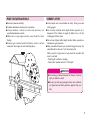
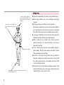
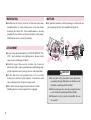
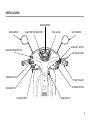
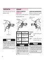
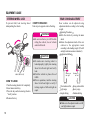
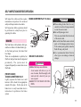
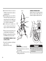
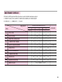
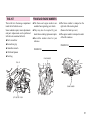
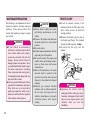
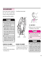
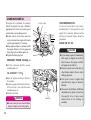
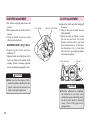
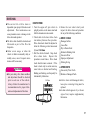
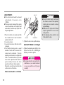
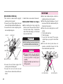
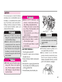
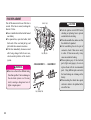
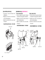
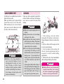
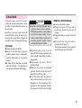
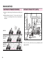
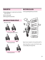
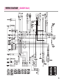
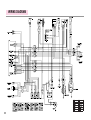
IMPORTANT NOTICE
OPERATOR AND PASSENGER
This vehicle is designed to carry the operator and one passenger.
ON-ROAD USE
This vehicle is designed to be used only on the road.
READ THIS OWNER'S MANUAL CAREFULLY
Pay special attention to statements preceded by the following words:
WARNING
Indicates a strong possibility of severe personal injury or death if instructions are not followed.
CAUTION
Indicates a possibility of personal injury or equipment damage if instructions are not followed.
NOTE
Gives helpful information.
This manual should be considered a permanent part of the motorcycle and should remain with the vehicle when resold or otherwise transferred
to a new owner or operator.
CONTENTS
SPECIFICATION
OPERATION INSTRUCTION
SAFETY PRECAUTIONS
3
4
HORN BUTTON
EQUIPMENT USAGE
15
16
4
STEERING WHEEL LOCK
16
PRIOR TO STARTING VEHICLE
5
REAR CUSHION ADJUSTMENT
16
CORRECT ATTIRE
5
SELF INSPECTIONS BEFORE OPERATION
17
OPERATION
6
BRAKES
CARGO
7
FUEL
20
MODIFICATION
8
TIRES
21
ATTACHMENT
8
ENGINE OIL LEVEL CHECK
22
MUFFLER
8
LIGHTS AND WINKER
22
9
BACK MIRROR
23
LICENSE PLATE
23
PARTS LOCATION
METER READING AND USAGE
12
OPERATION
17
METER
12
FUEL GAUGE
12
PRE-RIDE INSPECTION
23
INDICATOR LAMPS
12
STARTING THE ENGINE
24
25
SWITCH OPERATION
23
13
IF ENGINE CANNOT BE STARTED
MAIN SWITCH
13
RUNNING-IN
25
STARTER BUTTON
14
RIDING
26
HEADLIGHT
14
BRAKING
27
WINKER SWITCH
15
PARKING
27
1
MAINTENANCE
SAFE DRIVING
48
29
PREPARATION BEFORE DRIVING
48
TOOL KIT
31
DRIVING METHOD
49
FRAME AND ENGINE NUMBERS
31
DRIVING POSITION
49
MAINTENANCE PRECAUTIONS
32
PRECAUTION WHEN DRIVING
50
THROTTLE GRIP
32
STARTING
51
MAINTENANCE SCHEDULE
2
28
33
TURNING METHOD
52
34
PRINCIPLE OF TURN
52
SPARK PLUG
35
EFFECT OF SPEED
52
IDLE SPEED ADJUSTMENT
AIR CLEANER ELEMENT
CHANGINE ENGINE OIL
36
3 POSITIONS OF TURNING
53
CLUTCH ADJUSTMENT
36
TURNING METHOD
54
DRIVE CHAIN
37
PRECAUTION WHEN TURNING
55
WHEEL REMOVAL
39
SIDE STAND
BRAKING METHOD
56
40
BASIC PRINCIPLE OF BRAKE(FRICTION FORCE)
56
BATTERY
41
RESTRAINT OF BRAKING EFFECT (INERTIA)
56
FUSE REPLACEMENT
42
BRAKING METHOD
57
BULB REPLACEMENT
43
COMPARISION OF BRAKING DISTANCE
57
CABLE RUBBER PART
46
IMPACT WHEN COLLISION
57
CLEANING
46
STORAGE GUIDE
47
WIRING DIAGRAM
59
SPECIFICATION
ITEM
DATA
LENGTH×WIDTH×HEIGHT(mm)
1,910×700×1,080
WHEEL BASE(mm)
1,220
GROUND CLEARANCE(mm)
125
SEAT HEIGHT(mm)
765
DRY WEIGHT(kgf)
96
ITEM
TIRE SIZE
SUSPENSION
BRAKE
DATA
FR.
2.75-16-4PR
RR.
3.00-16-4PR
FR.
TELESCOPIC
RR.
SWING ARM
FR.
HYDRAULIC DISK
RR.
DRUM BRAKE
PASSENGER
2
ENGINE TYPE
AIR COOLED 4 STROKE
SPARK PLUG
C7HSA(NGK)
PISTON DISPLACEMENT(cc)
108.9
FUSE(A)
7
BORE AND STROKE(mm)
50×55.5
HEADLIGHT BULB
12V 35W/35W
STARTING SYSTEM
START MOTOR / KICK
STOP/TAIL LIGHT BULB
12V 21/5W
TRANSMISSION TYPE
4 STEPS ROTARY
WINKER BULB
12V 10W×4
IGNITION SYSTEM
C.D.I
POSITION LIGHT BULB (EUROPE ONLY)
12V 3W×2
BATTERY CAPACITY
12V 8AH(MF TYPE)
SPEEDOMETER LAMP
12V 3.4W
FUEL CAPACITY(ℓ)
4.0
WINKER INDICATOR LAMP
12V 3.4W×2
3
OPERATION INSTRUCTION
SAFETY PRECAUTIONS
This manual describes matters pertaining to correct operation,
safe operation and simple maintenance of the vehicle you
purchased.
To ensure more comfortable and safer operation, make sure to
read this manual carefully prior to operation.
●The photographs and drawings shown in this manual may
differ from those of actual vehicles due to changes in vehicle
specifications and modifications made.
●This vehicle is designed for 2 riders including the operator.
CAUTION
●Do not use polluted gasoline.
Using polluted gasoline will cause rust inside the
fuel tank, and will close the supply of fuel to the
carburetor, leading to an improper engine starting
or may cause serious damage to an engine.
●Do not use polluted or low-grade oil.
Always use genuine oil to protect and extend
motorcycle performance and its life span.
●If any failure occurs due to the use of polluted
gasoline or oil, such failure will be excluded from
being eligible for repairs under the warranty.
4
●Careful driving and the wearing of proper attire and safety
equipment are the most important factors in the safe operation
of the vehicle. Please obey traffic regulations and do not be
hurried and careless.
●Many new vehicle owners operate their newly purchased
vehicles with great care and attention to safety factors.
However, after becoming accustomed to the operations are
often discarded, which can lead to accidents. Please don't let
this happen to you and always approach the operation of your
vehicle with the safety considerations needed.
When operating the vehicle, always keep in mind and obey
the notes of precaution printed on the“Safety Precaution
Label”attached to the vehicle.
●Always wear helmet.
●Always put on gloves.
●Observe posted speed limits.
●Park vehicle away from people (especially
children) as the muffler can get very hot.
●For safety, do not illegally modify the vehicle.
●Regularly conduct specified maintenance
inspections. <Maintenance Inspection Points>
Brakes, Tires, Oil, Lights, Horn, Instruments
PRIOR TO STARTING VEHICLE
●Read user's manual carefully.
●Conduct maintenance checks prior to operation.
●Always maintain vehicle in clean status and carry out
specified maintenance checks.
●Make sure to stop engine and stay away from fire when
fueling.
●Exhaust gas contains harmful substance such as carbon
monoxide. Start engine in well-ventilated places.
CORRECT ATTIRE
●Always make sure to wear helmet for safety. Wear gloves and
safety goggles.
●Do not wear uniforms which might hinder operation. It is
dangerous if the uniform is caught by brake lever or by the
rotating part of drive chain.
●Do not wear slippers which might obstruct brake operation or
transmission gear operation.
●Many automobile/motorcycle accidents happen because the
automobile driver does not “see” the motorcyclist.
Make yourself conspicuous to help avoid the accident that
wasn’t your fault :
- Wear bright or reflective clothing.
- Don’t ride in another motorist’s “blind spot”.
WARNING
●Not wearing a helmet increases the chance of serious
injury or death in a crash.
●Be sure you and your passenger always wear a helmet,
eye protection and other protective apparel when you
ride.
5
OPERATION
A helmet should always be
worn and the helmet chin
strap should be securely
fastened.
Correct shirts or jackets with
tight-fitting sleeves should be
worn,
Always put on gloves.
Shoes should fit properly, and shoes having little or
no heel should be worn.
6
●Operators should naturally fix bodies to keep smooth driving.
●Please check whether or not you are unnaturally strained and
strung up.
●Driving pose has a great influence on safe operation.
Please always maintain the center of your body in the middle of
seat. Especially do not sit at the rear seat because it may lessen
the weight of front wheel and cause trembling steering wheel.
●A passenger should hold on to the vehicle or the operator with
both hands and keep both feet on the pillion step bar.
●When wanting to turn, slightly lean to body toward the
direction of the turn. It is unsafe if the body is not moved in
union with the vehicle.
●Curvy roads and poor, unpaved roads constantly change in
surface quality. Driving on these roads can be unsafe if certain
safety precautions are not followed.
●In order to safely drive through these driving conditions,
anticipate coming road conditions, slow down to at least half
the normal speed, and relax your shoulders and wrists while
securely holding the handles.
●Driving with one or both hands not holding the handles or the
front wheel lifted can cause severe injury or death of the driver
resulted from the turnover of the vehicle.
CARGO
●When carrying cargo, you must keep in mind that operating the
motorcycle, especially when turning, will be different.
●Make sure not to overload the vehicle with goods as this can
make the vehicle unstable during operation.
WARNING
●Overloading or improper loading can cause a crash and
you can be seriously hurt or killed.
●Follow all load limits in this manual.
CAUTION
MAXIMUM LOAD : 30kg
●Only load cargo in or on designated areas as
placing or fastening cargo to other areas can cause
damage to the vehicle.
●Do not place articles between the frame body
cover and engine as this can burn the goods.
●Do not attach large or heavy items (such as a
sleeping bag or tent) to the handle bars or fork.
Unstable handling or slow steering response may
result.
7
MODIFICATION
●Modification of vehicle structure of function deteriorates
manipulatability or causes exhaust noise to become louder
shortening the vehicle life. These modifications are not only
prohibited by law but also are the acts harmful to other people.
Modifications are not covered by warranty.
MUFFLER
●Pay particular attention to fellow passenger so that he/she can
prevent getting burnt by the hot muffler during travel.
ATTACHMENT
●Except designated attachment by DAELIM MOTOR CO.,
LTD., don't attach any extra lighting device, because it may
cause an early discharging of battery.
●Carefully inspect the accessory to make sure it does not
obscure any lights, reduce ground clearance and banking angle,
or limit suspension travel, steering travel or control operation.
●Do not add electrical equipment that will exceed the
motorcycle’s electrical system capacity. A blown fuse could
cause a dangerous loss of lights or engine power.
●This vehicle was not designed to pull a sidecar or trailer.
Handling may be seriously impaired of so equipped.
CAUTION
●Do not park in the place where many pedestrians
are passing through. Pedestrians or children can be
burned by contacting with the muffler.
●Fellow passenger care must pay enough attention
not to be burn by contacting with the muffler.
●If haystack or vinyl is stuck to the muffler, fire can
be occurred.
8
PARTS LOCATION
SPEEDOMETER
BACK MIRROR
GEAR POSITION INDICATOR
FUEL GAUGE
BACK MIRROR
HEADLIGHT SWITCH
HIGH/LOW BEAM SWITCH
FR. BRAKE LEVER
WINKER SWITCH
THROTTLE GRIP
STARTER BUTTON
HORN BUTTON
CHOCK LEVER
MAIN SWITCH
9
PARTS LOCATION
HEADLIGHT
FUEL TANK LID
(BENEATH THE SEAT)
BATTERY/FUSE
(INSIDE COVER)
RR. CUSHION
FR. TIRE
RR. TIRE
MAIN STEP BAR
MUFFLER
10
PILLION STEP BAR
KICK STARTER
REAR BRAKE PEDAL
CALIPER
BRAKE DISK
PARTS LOCATION
SEAT
TOOL BOX
AIR CLEANER ELEMENT
(INNER PART)
RR. CUSHION
FRONT FENDER
REAR FENDER
DRIVE CHAIN CASE
GEAR CHANGE PEDAL
SIDE STAND
MAIN STAND
PILLION STEP BAR
11
METER READING AND USAGE
METER
INDICATOR LAMPS
<SPEEDOMETER>
Indicates speed in km/h during travel.
Maintain legal speed limits to ensure safe
operation.
WINKER
SPEEDOMETER
<ODOMETER>
Indicates total operating distance in km.
FUEL GAUGE
ODOMETER
GEAR POSITION
INDICATOR
FUEL GAUGE
HEADLIGHT HIGH-BEAM
INDICATOR
Indicates amount of gasoline in fuel tank.
(The fuel gauge needle always indicates
gasoline level regardless of whether main
switch is in "OFF" position or in "ON"
position.) If needle is within E mark,
immediately fill gasoline. Balance at this
time is approximately 1.2 litres.
WARNING
●To avoid running out of fuel that
may result in a sudden stop.
12
<HEADLIGHT HIGH-BEAM INDICATOR>
Turned on wien the headlight is in highbeam position.
<WINKER INDICATOR>
If main switch is turned "ON" and winker
is activated, the winker located in the
direction of turning is turned ON.
<GEAR POSITION INDICATOR>
Displays the gear position when the main
switch is set to “ON” and the gear is
applied.
POSITION MARK
GEAR POSITION
N
1
2
3
4
NEUTRAL
1st
2nd
3rd
4th
The neutral gear indicator is turned “N”
when the gear is in the neutral position.
The position mark is displayed according
to corresponding the gear position.
SWITCH OPERATION
MAIN SWITCH
Main switch is used to turn on or turn off
engine.
Key
position
ON
ON
KEY
LOCK
MAIN
SWITCH
Key
Key
Starts engine. Power
cannot be
is supplied to
removed
electrical circuits.
Stops engine. Cuts
Key
off all electrical can be
circuits.
removed
Locks steering
Key
wheel. Cuts off all
can be
LOCK electrical circuits
and steering wheel
removed
is locked.
OFF
OFF
Function
WARNING
●Do not manipulate main switch key
during operation. If the main switch
key is placed on "Off" or "Lock"
position, all electrical system will not
function. Never operate the main
switch key during travel as it might
cause unexpected accidents, If it is
necessary to remove the main switch
key, stop the vehicle first prior to
removing.
CAUTION
●Prior to dismounting from the
motorcycle, make sure to lock the
steering wheel and remove key.
●If the key is left in "ON" position
without starting engine, battery is
discharged.
●Do not use a number of keys together
with a metal key holder. The keys
and the key holder may cause
scratches or other damage to the
cover while operating the motorcycle.
(Recommend cloth or leather key
holders)
13
STARTER BUTTON
If you press this button, starter motor runs
and engine is started.
HEADLIGHT
<TURNING ON HEADLIGHT>
(EUROPE ONLY)
Put main switch key in "ON" position and
manipulate headlight switch.
HEADLIGHT SWITCH
Switch position
STARTER BUTTON
CAUTION
●Do not press starter button repeatedly
because it consumes great amount of
power causing battery to be
exhausted sooner.
14
Function
(H)
Headlight, position lamp
and taillight turned on
(P)
Position lamp
taillight turned on
(OFF)
Light turned off
<HEADLIGHT HIGH OR LOW BEAM OPERATION>
High beam or low beam can be operated
by the use of high/low beam switch.
HEADLIGHT HIGH/LOW
BEAM SWITCH
HIGH BEAM
D(HI) ...... used when needing extra
light.
LOW BEAM
D(LO) ...... used when other vehicles
are present, in the city, etc.
CAUTION
CAUTION
●When you travel after sunset, put
headlight in low-beam. This lets
approaching vehicles know of your
position and is helpful to safe
driving.
●Use the high beam only in the
suburban road or when the usage of
the high beam not hinder the safe
driving of the car ahead.
WINKER SWITCH
Use winker switch when you change
course of travel to left or right.
<HOW TO USE>
If this switch is turned on when the main
switch is in "ON" status, winker is
brinking. To release winker operation,
return winker switch its original position.
HORN BUTTON
CAUTION
●The winker switch does not automatically turn back to its original
position after completing the turn.
Please set the switch back to its
center position after turning.
If horn button is pressed when main
switch is in "ON" position, horn is
sounded.
(R) ---- Used when making a right turn.
(L) ---- Used when making a left turn.
HORN BUTTON
WINKER SWITCH
15
EQUIPMENT USAGE
STEERING WHEEL LOCK
To prevent theft, lock steering wheel
when parking the vehicle.
REAR CUSHION ADJUSTMENT
<HOW TO RELEASE>
Take steps in opposite order of locking.
WARNING
●Do not turn the key to LOCK while
riding the vehicle; loss of vehicle
control will result.
CAUTION
MAIN SWITCH KEY
<HOW TO LOCK>
1. Turn the steering wheel to left completely.
2. Insert main switch key.
3. Press the key and turn steering wheel to
"Lock" position.
4. Remove the key.
●To make sure steering wheel is
locked properly, lightly turn steering
wheel to left and right and verify
lock.
●Park the vehicle in places free of
traffic.
●Prior to operation, turn the steering
wheel to left and right to verify if
turning angles of left and right are
equal.
Rear cushion can be adjusted using
adjustment knob according to the loading
weight.
Operating Procedure
●Park the vehicle by erecting the main
stand.
●Rotate the adjustment knob of the rear
cushion to the appropriate mode
according to the loading weight. (The left
and right cushion modes are identical.)
Application Method
Rotating to
the right
Weak cushion effect
Light cargo
Single driving
Rotating to
the left
Strong cushion effect
Heavy cargo
Tandem driving
CAUTION
●Make sure the adjuster marks on left
and right side are equal.
16
SELF INSPECTIONS BEFORE OPERATION
Self inspect the vehicle and have regular
maintenance inspections for increased
safety and the prevention of accidents.
Self inspections before operation should
be performed on a daily basis prior to
operating the vehicle.
BRAKE LEVER FREE PLAY : 10~20mm
10~20mm
BRAKES
The front brake is the hydraulic disk type,
and the rear brake is the drum brake type.
As the brake pad wear, the brake fluid
level drops.
There are no adjustments to perform, but
fluid level and pad wear must be inspected
periodically. The system must be
inspected frequently to ensure there are no
fluid leaks.
[FRONT BRAKE]
<BRAKE LEVER FREE PLAY>
Lightly squeeze the brake lever until
tension is felt to check for an appropriate
amount of free play. No free play in the
brake lever or overly loose brake lever is
indication of a problem in the brake
system.
<BRAKE FLUID LEVEL>
CAUTION
●When adding brake fluid, be very
careful not to allow foreign materials
to enter the reserve tank.
●Do not fill past upper level.
This can cause brake fluid to leak out
of the reserve tank.
●Do not let brake fluid contact vehicle
parts as this damages painted areas.
If oil contacts parts, quickly clean the
fluid off using a dry cloth.
●Use recommended brake fluid as
other types can undergo chemical
changes.
WARNING
●Brake fluid may cause irritation.
Avoid contact with skin or eyes. In
case of contact, flush thoroughly with
water and call a doctor if your eyes
were exposed.
●KEEP OUT OF REACH OF CHILDREN
LOWER LEVEL
17
●Check that the fluid level is above the
LOWER level mark with the vehicle in
an upright position.
●Check through access cover which is
observable through inspection groove
located between the front handle cover
and the right end section of headlight.
(Use of a flash is recommended.)
●Brake fluid must be added to the
reservoir whenever the fluid level
begins to reach the LOWER level mark.
<BRAKE PAD INSPECTION>
Operate brake and, if the brake pad wear
limit line reaches the brake disk side, it
indicates the pad has reached wear limit.
SCREWS
OIL CUP CAP
UPPER
LEVEL
DIAPHRAGM
PLATE
WEAR LIMIT LINE
DIAPHRAGM
1. Remove the screws and take oil cup
cap, diaphragm plate diaphragm off.
2. Replenish recommended brake fluid to
the UPPER level inside reserve tank.
RECOMMENDED BRAKE FLUID
is DOT3 or DOT4
3. Reinstall the diaphragm, diaphragm
plate, oil cup cap.
4. Tighten the screws securely.
18
BRAKE DISK
Other checks :
●Mark sure there are no fluid leaks.
●Check for deterioration or cracks in the
hose and fitting.
●Check the brake pad for wear when
refilling with brake fluid.
CAUTION
●The brake lever must be operated
several times after replacement of the
front brake pad.
[REAR BRAKE]
<BRAKE PEDAL FREE PLAY>
<REAR BRAKE SHOE INSPECTION>
Push the brake pedal with hands for
resistance and check if the pedal
movement appropriate.
If brake pedal movements is inappropriate, adjust the pedal free play using
the rear wheel brake adjuster nut.
After adjusting the brake, check the wear
of the brake shoe. While tightly
squeezing the rear brake pedal, if the “ ”
mark of the brake shoe is worn. Please
take the motorcycle to a service center for
repair.
●To adjust pedal free play, turn adjuster
nut. After adjustment, push the brake
pedal with hands until you feel
resistance and verify the pedal free play
is within prescribed level.
"▲" MARK
"△" MARK
BRAKE PEDAL
BRAKE PEDAL FREE PLAY : 20~30mm
CAUTION
●After adjusting the brake, make sure
that “ ” part of the adjuster contacts
the pin. Brake clearance can change
when driving if this is not done.
CAUTION
ADJUSTER NUT
●If the vehicle becomes worn-out, the
replacement cycle of shoe may differ
depending on the wear condition of
the rim drum.
19
FUEL
<FUEL CHECK>
Check gasoline to see if there is a
sufficient amount of gasoline to reach
your destination.
SEAT
●If the fuel gauge needle indicates E
mark (red portion), fill fuel tank with
gasoline as soon as possible.
FUEL TANK CAP
Reserve fuel capacity :
Approximately 1.2 liter
<FUEL COCK>
The fuel cock lever arrow indicates
operating position.
●ON --- Gasoline is supplied. Set fuel
cock to this position when starting
engine.
●OFF -- Fuel is not supplied. Set to this
position except when the vehicle is
operated.
"△" MARK
CAUTION
E mark
<REFUELING>
●Erect the seat.
●Fill the fuel after opening the fuel tank
cap.
●Turn the fuel tank cap clockwise until
the "△" mark on the fuel tank cap is
aligned with the "△" mark located
above the fuel tank.
20
●Make sure to stop engine and stay
away from fire when fueling.
●If gasoline is filled above the level
plate bottom, gasoline may overflow.
CAUTION
●After refueling, turn lever to "ON"
position. If the lever is not turned to
"ON" reserve fuel runs out during
travel and vehicle cannot be
operated.
TIRES
<TIRE PRESSURE CHECK>
Check for an appropriate level of air
pressure by examining how the tire sits on
the ground. If you notice any abnormalities in the shape of the tire with regard to
the area contacting the ground, use a tire
gauge to check tire pressure and adjust the
tire pressure to the appropriate level.
<CRACKS/DAMAGE>
Check tire tread and sides for cracks and
damage.
CRACKS
<FOREIGN MATERIALS>
Check tire tread and sides for nails, rocks,
etc. That might have become wedged in
the tire.
NAIL
ROCK
<TIRE PRESSURE>
SIZE
TIRE
PRESSURE
(kgf/ )
2.75-16-4PR
3.00-16-4PR
1.75
FRONT
1 PERSON
RIDING REAR 2.00
FRONT
REAR
2 PERSON FRONT
RIDING REAR
1.75
2.25
DAMAGE
<ABNORMAL WEAR>
Check tire tread for signs of abnormal
wear.
ABNORMAL
WEAR
<TREAD DEPTH>
●Check the wear indicator (wear limit
marking) to see if there is an
insufficient amount of tread remaining.
●If the indicators are visible, replace tire
with a new one.
WEAR INDICATOR
(WEAR LIMIT MARKING)
WEAR INDICATOR
LOCATION MARKING
21
ENGINE OIL LEVEL CHECK
CAUTION
●If air pressure is inadequate or if
there are cracks, damage or abnormal
wear on tires, it may cause trembling
steering wheel and flat tire.
●Insufficient air pressure may cause
the heavy steering wheel marking
handling difficult, fuel over consumption and the excessive wear of
tire outer area and excessive air
pressure may cause easier wheel
handling and lower fuel consumption. But it may also cause the
excessive wear of tire center area.
●This motorcycle is equipped with
tubeless tires. If you have flat tires,
please contact authorised maintenance shops for inspection.
Put vehicle in upright position on flat
ground and check engine oil level and
degree of pollution.
●Run engine idle for approximately 2~3
minutes and stop engine.
Approximately 2~3 minutes thereafter,
check engine oil and verify the oil level
is between the upper and lower level of
oil level gauge.
●Insert oil level gauge, without locking,
and check oil level after removing oil
gauge.
●If the oil level is near lower level,
replenish oil to upper level.
OIL LEVEL GAUGE
UPPER
LEVEL
LOWER
LEVEL
22
LIGHTS AND WINKER
<HEADLIGHT, TAILLIGHT>
Start the engine and make sure the lights
turn on. Also check to see if the lights are
damaged or if there is dirt on them.
<BRAKE LIGHT CHECK>
Turn the main switch to ON.
While separately operating the front and
rear brakes, check to see if the brake light
turns on. Also check to see if there is any
damage to the lens or if there is dirt on the
brake light.
<WINKER CHECK>
Turn the main switch to ON.
Check to see if all the winker in the front
and rear of the vehicle (including left and
right sides) are flashing properly. At the
same time, check to make sure that the
automatic sound signal of the winker is
working. Check also to see if any of the
lens are damaged or dirty.
OPERATION
BACK MIRROR
Sit squarely on the seat and check to see if
you have a good view behind the vehicle
by looking at the back mirrors. Also check
for dirt and damage on the back mirrors.
LICENSE PLATE
Check to see if there is any dirt or damage
to the license plate.
Also check to see if the license plate is
firmly secured to the vehicle.
PRE-RIDE INSPECTION
WARNING
●If the pre-ride inspection is not
performed, severe personal injury or
vehicle damage may result.
Inspect your vehicle every day before you
ride it. The items listed here will only
take a few minutes to inspect, and in the
long run they can save time, expense, and
possibly your life.
●Check for signs of abnormality which
might have occurred on the previous
day.
●Engine oil level - add engine oil if
required (page 22). Check for leaks.
●Fuel level - fill fuel tank when necessary
(page 20). Check for leaks.
●Front and rear brakes - check operation;
make sure that is no brake fluid leakage
(page 17~19).
●Tires - check condition and pressure
(page 21~22).
●Drive chain - check condition and slack
(page 37~38). Adjust and lubricate if
necessary.
●Throttle - check for smooth opening
and full closing in all steering positions.
●Lights and horn - check that headlight,
tail/brake light, turn signals, indicators
and horn function properly.
●Angle rear view mirror.
CAUTION
●Observe safety rules when conducting inspections.
●Conduct inspections on a flat, solid
ground with the main stand erected.
If you are unable to correct trouble even
after you make adjustment or correction,
contact authorized maintenance shops,
dealers or designated repair shops for
necessary inspection and repairs.
23
STARTING THE ENGINE
Always follow the proper starting
procedure described below.
●This vehicle is equipped with a side
stand ignition cut-off system. The
engine cannot be started if the side
stand is down.
WARNING
●Never run the engine in an enclosed
area. The exhaust contains poisonous
carbon monoxide gas that can cause
loss of consciousness and lead to
death.
<PREPARATION>
Before starting, insert the key, turn the
ignition switch ON and confirm the
following:
●The transmission is in NEUTRAL
(neutral indicator light ON)
●The fuel cock is ON.
<WHEN ENGINE IS COLD (WINTER)>
1. Open choke lever completely.
CHOKE LEVER
CAUTION
●Do not keep the starter button
pressed for more than 5 seconds at a
time. Release the starter button for
approximately 10 seconds before
pressing it again.
24
2. Close throttle grip, and press starter
button.
3. Once engine is started, pull and release
throttle grip repeatedly to run engine
idle until engine is heated, and close
choke lever completely. If engine
warming up takes time, run engine idle
with the choke lever slightly closed.
<WHEN ENGINE IS HOT (SUMMER)>
1. Close throttle grip and press starter
button. (If engine is not started with 1-2
times trial, verify fuel cock lever is in
"ON" position)
2. If engine is not started with throttle grip
closed, open throttle grip approximately
1/8 to 1/4 and press starter button.
IF ENGINE CANNOT BE STARTED
●It is possible that starting will be more
difficult if the vehicle has not been used
for a long period of time or if the fuel
hole is plugged up (starting problems
even when there is sufficient fuel in the
fuel tank may be an indication of a
plugged fuel hole).
When this happens, do not rotate the
throttle grip and try the starter button a
few times.
NOTE
●Do not run engine idle unreasonably.
This not only wastes fuel but also
adversely affects engine.
●If starter button is pressed in gear
position, vehicle may bring out to
fall. Make sure gear is in neutral
position prior to starting engine.
If engine cannot be started or vehicle does
not move, check the followings.
●Is there fuel in fuel tank?
●Are you operating in accordance with
the instructions given in user's manual?
●Is fuse not cut?
●Is starter motor running?
●If starter motor is not running due to
battery consumption, try starting motor
by using kick start technique.
RUNNING- IN
During initial running-in newly machined
surfaces will be in contact with each other
and these surfaces will wear in quickly.
Running-in maintenance at 1,000km is
designed to compensate for this initial
minor wear.
Timely performance of the running-in
maintenance will ensure optimum service
life and performance from the engine.
The general rules as follows:
1. Never labour the engine with full
throttle at low engine speeds. This rule
is applicable not only during running-in
but at all times.
2. Maximum continuous engine speed
during the first 1,000km must not
exceed 5,000 rpm.
CAUTION
●Running the engine beyond recommended maximum engine speed can
damage the engine.
25
RIDING
NOTE
●Make sure you understand the
function of the side stand mechanism.
(see explanation for SIDE STAND
on page 39)
1. After the engine has been warmed up,
the vehicle is ready for riding.
2. While the engine is idling, depress the
gearshift pedal to shift into 1st (low)
gear.
3. Gradually increase engine speed by
opening the throttle.
4. When the vehicle attains a mode-rate
speed, close the throttle and shift to 2nd
gear by depressing the gearshift pedal.
This sequence is repeated to progressively shift to 3rd, 4th (top) gear.
5. Coordinate the throttle and brakes for
smooth deceleration.
6. Both front and rear brakes should be
used at the same time and should not be
applied strongly enough to lock the
wheel, or braking effectiveness will be
reduced and control of the vehicle be
difficult.
26
<GEAR SHIFTING>
Operating method of the gear is different
between stopping and driving.
●Drectly gear changing from top gear
position to neutral is possible when
stopping.
●When driving, gear changing is
performed by 4th gear return type and
gear changing from top gear position to
neutral is impossible.
●When stopping gear changing from 4th
gear position to neutral is possible.
●When changing gear during driving,
change the gear after making the speed
high enough to change the gear.
WHEN DRIVING
WHEN STOPPING
<GEAR DOWN OPERATION>
If you gear down when you need to
drastically accelerate speed such as when
you are passing another vehicle, speed can
be accelerated. If you ride too fast, it
adversely affects engine because engine
revolution is excessive.
NOTE
●Make sure side stand is in original
position prior to starting vehicle.
If side stand moves unsatisfactorily,
check lubrication state on side stand
joint.
●Shift gear adequately according to
vehicle speed.
●To save fuel and maintain optimum
vehicle life, do not accelerate or
decelerate speed abruptly.
●Always start in the 1" gear, and start
carefully as slow as possible.
●If you hear abnormal noise during
travel, contact authorized maintenance shop immediately for
inspection and necessary action.
●Maintain legal speed limits.
BRAKING
PARKING
1. For normal braking, gradually apply
both the front and rear brakes while
down shifting to suit your road speed.
2. For maximum deceleration, close the
throttle and apply the front and rear
brakes firmly.
WARNING
●If you apply brakes only on front
wheel or rear wheel, vehicle may
slide off sideway and fall.
●If you apply brakes abruptly during
travel in rain or on wet road, tires
slide off and may cause accidents.
Reduce speed and apply brake
cautiously.
●Avoid repeated brake operation as it
may cause brake temperature to rise,
leading to braking effect deterioration.
●When possible, reduce speed or
brake before entering a turn; closing
the throttle or braking in mid-turn
may cause wheel slip. Wheel slip
will reduce control of the vehicle.
<ENGINE BRAKE>
If you turn throttle grip in reverse, engine
brake functions and, if you need stronger
braking, shift gear down from 4th to 3rd
and so forth. When you travel on a long
descent or on a sharp descent, use
intermittent braking technique and engine
brake simultaneously.
CAUTION
●Do not shift to lower gear while
traveling at an excessive speed as it
may suddenly increase the engine
speed, adversely affect the engine
and transmission, and cause the rear
part of the vehicle to be shaken.
1. After stopping the vehicle, shift the
transmission into neutral, turn the fuel
cock OFF, turn the ignition switch OFF
and remove the key.
2. Put the vehicle on main stand and park
on level ground in places free of traffic.
3. Use the side stand to support the
vehicle while parked.
4. Turn the handlebar fully to the left and
lock the steering to help prevent theft.
CAUTION
●Park the vehicle on firm, level ground
to prevent it from falling over.
●Park in a safe area that will not block
traffic. When you parked the vehicle
after driving, make sure foot the
vehicle beyond man's reach because
engine and muffler are still hot.
●If you must park on a slight incline,
aim the front of the vehicle uphill to
reduce the possibility of rolling off the
side stand or overturning.
27
MAINTENANCE
●The Required Maintenance Schedule specifies how often you should have your vehicle served, and what things need attention.
It is essential that your vehicle be served as scheduled to retain its high level of safety, dependability, and emission control
performance.
●These instructions are based on the assumption that the motorcycle will be used exclusively for its designed purpose. Sustained high
speed operation, or operation in unusually wet or dusty conditions, will require more frequent service than specified in the
MAINTENANCE SCHEDULE.
Consult your authorized Daelim dealer for recommendations applicable to your individual needs and use.
28
MAINTENANCE SCHEDULE
Perform the Self Inspections Before Operation at each scheduled maintenance period.
I: INSPECT AND, CLEAN, ADJUST, LUBRICATE OR REPLACE IF NECESSARY
R: REPLACE L: LUBRICATE C: CLEAN
ODOMETER READING(NOTE1)
FREQUENCY
ITEM
×1,000Km
1
4
8
12
16
MONTH
1
6
12
18
24
★
FUEL LINE
I
I
I
I
★
FUEL FILTER
R
R
R
R
★
THROTTLE OPERATION
I
I
I
I
I
★
CARBURETOR CHOKE
I
I
I
I
I
AIR CLEANER ELEMENT
C
C
C
C
SPARK PLUG
I
R
I
R
★
VALVE CLEARANCE
I
I
I
I
★
CARBURETOR IDLE
I
I
I
I
I
★
ENGINE OIL
R
R
R
R
R
ENGINE OIL FILTER
R
R
R
R
R
★★
DRIVE CHAIN
REMARK
NOTE( 2)
Every 1,000Km : I and L
29
ODOMETER READING(NOTE 1)
FREQUENCY
ITEM
×1,000Km
1
4
8
12
16
MONTH
1
6
12
18
24
★
BRAKE FLUID
I
I
I
I
R
★
BRAKE SHOE / PAD WEAR
I
I
I
I
I
BRAKE SYSTEM
I
I
I
I
I
★
BRAKE STOP SWITCH
I
I
I
I
I
★
HEADLIGHT ADJUSTMENT
I
I
I
I
I
★
SUSPENSION
I
I
I
I
I
I
I
I
I
I
I
I
CLUTCH
I
SIDE STAND
★
BOLTS, NUTS, FASTENERS
I
I
I
I
I
★★
WHEELS / TIRES
I
I
I
I
I
★★
STEERING HANDLE BEARING
I
I
I
I
I
REMARK
NOTE( 3)
★ If you do not have the appropriate tools or information to conduct maintenance, or if you feel you are not capable to perform
maintenance on this vehicle, contact authorized dealers or repair shops for maintenance and repairs.
★★To ensure safety, inspections and maintenance of these parts must be carried out by dealers, or repair centers.
NOTES : (1) At higher odometer readings, repeat at the frequency interval established here.
(2) Service more frequently when riding in unusually wet or dusty areas.
(3) Replace every 2 years, or at indicated odometer interval, whichever comes first. Replacement requires mechanical skill.
30
TOOL KIT
FRAME AND ENGINE NUMBERS
The tool kit is in the storage compartment
inside the left sub side cover.
Some roadside repairs, minor adjustments
and parts replacement can be performed
with the tools contained in the kit.
●No.2 screwdriver
●Screwdriver grip
●16mm Box wrench
●10x12mm Spanner
●Tool bag
●The frame and engine numbers are
needed when registering your vehicle.
●They may also be required by your
dealer when ordering replacement parts.
●Record the numbers here for your
reference.
●The frame number is stamped on the
right side of the steering head.
(Remove the front top cover)
●The engine number is stamped on under
of the left crankcase.
ENGINE NO.
FRAME NO.
FRAME NUMBER
TOOL KIT
ENGINE NUMBER
LEFT SUB SIDE COVER
31
MAINTENANCE PRECAUTIONS
The following is an explanation of correct
inspection methods, cleaning and parts
replacing. Please always refer to this
section when wanting to inspect or repair
your vehicle.
WARNING
●If your vehicle is overturned or
involved in a collision, inspect control
levers, cables, brake hoses, calipers,
accessories, and other vital parts for
damage. Do not ride the vehicle if
damage impairs safe operation. Have
your authorized Daelim dealer inspect
the major components, including
frame, suspension and steering parts,
for misalignment and damage that you
may not be able to detect.
●Use new, genuine Daelim parts or their
equivalent for maintenance and repair.
Parts which are not of equivalent
quality may impair the safety of your
motorcycle and the effective operation
of the emission control systems.
32
THROTTLE GRIP
CAUTION
●Always observe safety rules when
performing maintenance on the
vehicle.
●Choose a flat surface and make sure
the main stand is in a secure down
position.
●Use correct tools.
●Conduct engine maintenance with the
engine key out of the ignition.
●Be careful around the engine and
muffler when performing maintenance as these areas can become
extremely hot.
●After self maintenance, the waste
material must be packed in the
specified container and entrusted
disposal to the authorized disposal
company.
●Exhaust gas contains harmful
substance such as carbon monoxide.
Do not carry out inspections on
vehicle in closed places, or in poorly
ventilated places, with engine
running.
●Check for smooth rotation of the
throttle grip from the fully open to the
fully closed position at both full
steering positions.
●Measure the throttle grip free play at
the throttle grip flange. The standard
free play should be approx : 2-6mm
●To adjust the free play, turn the
adjuster.
THROTTLE GRIP
ADJUSTER
WARNING
●Operating the vehicle with an
inadequate throttle cable play can be
hazardous. Inadequate throttle cable
play can cause engine speed to rise
suddenly when you turn the
handlebars.
AIR CLEANER ELEMENT
If the air cleaner element is clogged with
dust, there will be greater intake
resistance, resulting in decreased power
output and increased fuel consumption.
3. Take off the air cleaner element.
CAUTION
●Do not operate the engine without the
air cleaner element in place or severe
engine damage may result.
●If you usually ride in dusty areas or
regularly operate in vehicle in wet,
muddy conditions, you must inspect
the air cleaner element more frequently than shown in the maintenance schedule.
●If, at any time, the air cleaner
element is submerged in water,
immediately clean the element and
the inside of the air cleaner cover.
<REMOVING THE ELEMENT>
1. Remove the front top cover and the L,R
front covers.
2. Loosen the 4washer screws and remove
the air cleaner cover.
OIL : SAE 10W-30
2. Make sure all excess oil removed and
reassemble the air cleaner element.
WARNING
CARBURETOR
AIR CLEANER
●Be sure to keep cleaning solvent and
oil away from children and pets.
Dispose of used solvent and oil
properly.
CAUTION
<WASHING THE ELEMENT>
1. Clean the air cleaner element in clean
oil, squeeze excess oil, and then, wrapping it in a dry cloth, squeeze it again.
●If air cleaner element is inadequately
assembled, dust and other waste
materials are absorbed directly
inducing cylinder wear and output
deterioration, and adversely affecting
engine durability. Assemble correctly.
33
CHANGING ENGINE OIL
If engine oil is polluted, it seriously
affects the engine life span. Maintain
appropriate level of oil, use correct type of
oil and observe oil exchange period.
●Stand vehicle on the main stand on
level ground and run engine idle (warm
up) for approximately 2-3 minutes.
●Stop engine and place a container under
the engine. Remove oil level gauge and
drain plug bolt, and drain engine oil.
●Tighten the drain plug bolt.
OIL LEVEL GAUGE
UPPER
LEVEL
LOWER
LEVEL
CAUTION
·m
DRAIN BOLT TORQUE: 2.0-3.0kgf·
●Fill the crankcase with the recommended grade oil.
OIL CAPACITY : 0.75
●Start the engine and keep it idle for a
few minutes.
●Stop the engine and check the oil level.
If the oil level is low, add the recommended engine oil.
●Check on oil leaks.
WARNING
●Be sure to keep oil away from children
and pets. Dispose of used oil properly
34
<RECOMMENDED OIL>
If oil sold on markets or privatelymanufactured oil (low-grade) is used,
engine life is adversely affected, and the
privilege of warranty repairs cannot be
guaranteed.
GRADE (SE, SF, SH)
DRAIN PLUG
●If you change engine oil immediately
after engine is stopped, be careful of
burns because the engine, muffler
and engine oil are still hot.
●Exercise caution not to allow dust or
other foreign matter to flow in when
refilling engine oil.
●If oil level is lower or higher than
prescribed level, engine is adversely
affected.
●Do not mix oil with those of different
manufacturers or grade, or do not use
low-quality oil as it may cause
deterioration of oil, leading to
accidents.
SPARK PLUG
If electrode is stained or clearance is not
right, satisfactory spark is not produced.
Clean and make adjustment.
●If new plug is installed, turn 1/2 and
tighten using a plug wrench.
If plug is reused, turn 1/3-1/4 and
tighten.
PLUG GAP
CAUTION
SPARK
PLUG
SPARK
PLUG CAP
●Remove spark plug cap.
●Clean around the plug.
●Using a plug wrench, remove plug.
●Clean plug with plug cleaner.
●Check electrode for wear and corrosion.
If the center of electrode became round,
replace the electrode.
●Measure clearance using a feeler gauge.
PLUG GAP : 0.6-0.7mm
●Tighten with hands until the plug
washer touches cylinder head.
STANDARD PLUG : C7HSA(NGK)
·m
PLUG TORQUE: 14 kgf·
●If plug of different maker or different
heat value is used, it causes
unsatisfactory engine starting,
inadequate engine revolution and
output deterioration.
●The spark plug must be securely
tightened. An improperly tightened
plug can become very hot and
possibly damage the engine.
●To install a spark plug, turn it in as
far as possible with your fingers, then
tighten it with a wrench.
Do not overtighten or cross thread
the spark plug or the aluminum
threads of the cylinder head will be
damaged. Do not allow contaminants
to enter the engine through the spark
plug hole when the plug is removed.
<DEALING WITH POOR STARTING>
When the starter doesn't work during
driving in winter times or in a repeated
short distance, use the suitable spark plug
for this driving condition.
Poor starting may happen when nonstop
driving in low speed, even though we
produce standard plug.
In case starter isn't working well in
driving repeatedly in a short distance or in
an area with many traffic signals, use the
C6HSA plug instead of standard plug
C7HSA.
35
IDLE SPEED ADJUSTMENT
1. Put vehicle in upright position on a flat
ground.
2. Start engine and let in run idle for a few
minutes.
3. Using the throttle stop screw, adjust
idling to prescribed level.
IDLE REVOLUTION: 1,600
100rpm
4. Tighten up pilot screw and loose
backward 3/4.
5. Operate throttle lever lightly and verify
there is no change in the number of idle
running. If there is a change, repeat the
process described in paragraph 3 and 4.
CLUTCH ADJUSTMENT
PILOT SCREW
THROTTLE STOP SCREW
● Adjust the clutch only after turning off
the engine.
① There are two types of clutch ; one-way
clutch and clutch.
② Adjust the clutch as follows ; Loosen
the lock nut and turn the clutch
adjuster clockwise until it stops and
then counterclockwise. At this time,
turn the adjuster 1/8〜1/4 turn from
where the screw get caught and tighten
the lock nut completely.
CLUTCH ADJUSTER
LOCK NUT
CAUTION
●Make sure that the engine is fully
warmed up before adjusting the idle
speed. Improper adjustment can
result in increased engine wear.
36
CAUTION
●When the adjustment is completed,
the clutch must not slide when
starting the engine and starting using
the kick starter must be obtained
easily. Check if the gear can be
changed easily.
DRIVE CHAIN
●The service life of drive chain is
dependent upon proper lubrication and
adjustment. Poor maintenance can
cause premature wear or damage to the
drive chain and sprocket.
●The drive chain should be checked and
lubricated as part of the Pre-ride
Inspection.
●Under severe usage, or when the
vehicle is ridden in unusually dusty or
muddy areas, more frequent maintenance will be necessary.
WARNING
●For your safety, drive chain condition
and adjustment should be checked
prior to each use of the vehicle.
Always follow the manufacturer’s
recommendations for proper lubrication and replacement of the chain.
<INSPECTION>
1. Turn the engine off, put vehicle in
upright position on the main stand and
shift the transmission into neutral.
2. Check slack in the lower drive chain
run midway between the sprockets.
Drive chain slack should be adjusted to
allow the following vertical movement
by hand: 20-30mm
3. Roll the vehicle forward. Stop check
drive chain slack. Repeat this
procedure several times. Drive chain
slack should remain constant. If the
chain is slack only in certain sections,
some links are kinked and binding,
Binding and kinking can frequently be
eliminated by lubrication.
20~30mm
4. Rotate the rear wheel slowly and
inspect the drive chain and sprockets
for any of the following conditions:
■ DRIVE CHAIN
Damaged rollers
Loose Pins
Dry or Rusted Link
Kinked or Binding Link
Excessive Wear
Improper Adjustment
Missing O-ring
■ SPROCKETS
Excessively Worn Teeth
Broken or Damaged Teeth
●A drive chain with damaged rollers,
loose pins or missing O-ring must be
replaced.
●A chain which appears dry or shows
signs of rust, requires supplementary
lubrication.
37
<ADJUSTMENT>
●Drive chain slack should be checked
and adjusted, if necessary, every
1,000km.
●When operated at sustained high speeds
or under conditions of frequent rapid
acceleration, the chain may requir more
frequent adjustment.
1. Place the vehicle on its main stand with
the transmission in neutral and the
ignition switch off.
2. Loose the axle nut.
3. Loose the lock nuts on both sides of the
swingarm.
4. Turn both adjusting nuts an equal
number of turns until the correct drive
chain slack is obtained. Turn the
adjusting nuts clockwise to tighten the
chain or counterclockwise to provide
more slack. Adjust the chain slack at a
point midway between the drive
sprocket and the rear wheel sprocket.
Rotate the rear wheel and recheck slack
at other section of the chain.
Chain slack should be : 20~30mm
38
AXLE NUT
LOCK NUT
ADJUSTER NUT
5. Tighten the axle nut to specified torque.
AXLE NUT TORQUE : 4.0~5.0kgf.m
6. Tighten the adjusting nuts lightly, then
tighten the lock nuts by holding the
adjusting nuts with a spanner.
WARNING
●If a torque wrench is not used for this
installation, see your authorized dealer
as soon as possible to verify proper
assembly.
CAUTION
●Excessive chain slack could cause
the chain to come off the sprockets,
resulting in loss of control or serious
engine damage.
●Make sure the right and left chain
adjuster graduations are set in the
same position.
●After adjusting chain, check the rear
brake pedal free play.
WHEEL REMOVAL
[FRONT WHEEL REMOVAL]
1. Raise the front wheel off the ground by
placing a support block under the
engine.
2. Loose the oval screw and remove the
speedometer cable.
3. Remove the front caliper assembly
from the fork by removing the fixing
bolts.
4. Loosen the axle nut.
5. Withdraw the front wheel axle and
remove the front wheel.
FRONT WHEEL AXLE
SPEEDOMETER
CABLE
AXLE NUT
●Prior to assembling, match the
depressed part( ) of the speedometer
gear box with the projected part of the
left front fork.
●Fit the caliper over the disk, taking care
not to damage the brake pads. Install
the caliper fixing bolts, and tighten to a
torque of : 2.7kgf.m
●Tighten the front axle nut to the
specified torque.
FRONT AXLE NUT TORQUE :
5.0~7.0kgf.m
●After assembling, operate brake for a
number of times and see if wheel is
turning smoothly without getting
interruption.
FRONT CALIPER
OVAL SCREW
6. Install in the reverse order of removal.
CAUTION
CAUTION
●Do not operate brake lever after the
front wheel is removed. If will make
wheel assembling difficult.
●When installing the wheel, carefully
fit the left brake disk between the
brake pads to avoid damaging the
pads.
WARNING
●If a torque wrench was not used for
installation, see your authorized dealer
as soon as possible to verify proper
assembly.
Improper assembly may lead to loss of
braking capacity.
39
SIDE STAND
[REAR WHEEL REMOVAL]
1. Set vehicle on main stand in upright
position on level ground.
2. Loosen the rear brake adjuster nut and
remove the brake rod from the brake arm.
3. Loosen the drive chain adjusting lock
nuts and adjusting nuts.
LOCK NUT
ADJUSTER NUT
6. Install in the reverse order of removal.
REAR AXLE NUT TORQUE : 4.0~5.0kgf.m
●After installing the wheel, apply the
brake several times and then check if
the wheel rotates freely. Recheck the
wheel if the brake drags or if the wheel
does not rotate freely.
CAUTION
●After installing the wheel, adjust the
rear brake and drive chain free play.
AXLE NUT
WARNING
BRAKE ARM
BRAKE ADJUSTER NUT
BRAKE ROD
4. Loosen the rear brake stopper bolt
securing the rear brake panel.
5. Loosen the rear weel axle nut and
remove the rear wheel axle and the rear
wheel.
40
●Erect main stand and place vehicle in
upright position on level ground.
●Check the spring for damage or loss of
tension and the side stand assembly for
freedom of movement.
●Check the side stand ignition cut-off
system;
① Put the side stand up.
② Start the engine.
③ Lower the side stand. The engine
should stop as you put the side stand
down.
●If the side stand system does not
operate as described, inspect it in the
closest authorized repair center.
●If torque wrench was not used for
installation, see you authorized dealer
as soon as possible to verify proper
assembly.
Improper assembly may lead to loss of
braking capacity.
SIDE STAND SPRING
SIDE STAND SWITCH
BATTERY
It is not necessary to check the battery
electrolyte level or add distilled water as
the battery is a maintenance-free (sealed)
type. If your battery seems weak and/or is
leaking electrolyte (causing hard starting
or other electrical troubles), contact your
authorized Daelim dealer.
CAUTION
●Removing the battery cap strip can
damage the cap strip and result in leaks
and eventual battery damage.
●When the vehicle is to be stored for an
extended period of time, remove the
battery from the vehicle and charge it
fully. Then store it in a cool, dry place. If
the battery is to be left in the vehicle,
disconnect the negative cable from the
battery terminal.
WARNING
●The battery gives off explosive gases;
keep sparks, flames, and cigarettes
away. Provide adequate ventilation
when charging or using the battery in
an enclosed space.
WARNING
●Battery acid is poisonous and
corrosive. Avoid contact with eyes,
skin, clothing, and painted surfaces.
If battery acid comes in contact with
any of these, flush immediately with
large amounts of water.
If acid contacts the eyes or skin, get
medical attention.
●KEEP OUT OF REACH OF CHILDREN.
●Even though the battery is sealed, it
still vents explosive gases.
Do not allow open flames or sparks
near the battery.
<BATTERY REMOVAL>
1. Turn the ignition switch OFF.
2. Loosen the 2 special screws and remove
the right side cover.
3. Remove the battery holder by removing the
mount bolt.
terminal lead
4. Disconnect the negative
from the battery first, then disconnect the
positive terminal lead.
5. Pull out the battery from the battery box.
BATTERY HOLDER
BATTERY
CAUTION
●Make sure that terminals do not contact
with other adjacent parts when handling
terminals.
<CLEANING BATTERY TERMINALS>
●If the battery terminal is polluted, or in
rust, separate battery and clean it.
●Battery terminal in rust with white
powder should be cleaned with warm
water. In case of serious rust of battery
terminal, disassemble the battery cord and
grind it with wirebrush or sandpaper.
41
FUSE REPLACEMENT
Turn off the main switch to see if the fuse is
severed. If the fuse is severed, exchange the
fuse into 7A fuse.
●Fuse is installed inside fuse holder located
near battery.
●To separate fuse, open fuse holder, hold
both ends of fuse cord and pull up, and
pull out the fuse connector crosswise.
●If the fuse immediately becomes severed
after being changed with the new one,
check another problem of the electric
system.
SPARE FUSE
FUSE HOLDER
<DISASSEMBLY>
WARNING
●Never use a fuse with a different rating
from that specified. Serious damage to
the electrical system or a fire may
result, causing a dangerous loss of
lights or engine power.
CORD
FUSE CONNECTOR
42
<ASSEMBLY>
CAUTION
●Turn the ignition switch OFF before
checking or replacing fuse to prevent
accidental short-circuiting.
●When disassemble fuse, make sure that
fuse holder isn't separated.
●After assembling fuse in the part of
connector, check if fuse moves easily
to a line. If fuse moves easily, it may
cause an accident at heating.
●When replacing any of the electrical
parts (lights and gauges), be sure to
replace them with the recommended
parts. Using different parts can lead to
the fuses burning out or damage to the
battery.
●When washing the vehicle take special
card not to allow to be splashed in the
area of the fuse.
BULB REPLACEMENT
●Be sure to turn the ignition switch OFF
when replacing the bulb.
●Do not use bulbs other than that
specified.
●After installing a new bulb, check that
the light operates properly.
WARNING
●The light bulb becomes very hot while
the light is ON, and remain hot for a
while after it is turned OFF. Be sure to
let it cool down before servicing.
CAUTION
●Do not put finger prints on the
headlight bulb, as they may create
hot spots on the bulb and cause it to
break. Wear clean gloves while
replacing the bulb.
If you touch the bulb with your bare
hands, clean it with a cloth moistened
with alcohol to prevent its early
failure.
[HEADLIGHT BULB]
●Before replacing the bulb, be sure to
check the switches for loose connection
of the connector.
FRONT HANDLE COVER
1. Remove the back mirrors.
2. Loosen the 4 screws and remove the
front handle cover.
3. Slightly press down on the bulb holder
and turn it counterclockwise.
4. Slightly press down on the socket and
turn it counterclockwise.
5. Install a new bulb in the reverse order
of removal.
SCREWS
HEADLIGHT BULB : 12V 35/35W
HEADLIGHT BULB
HEADLIGHT SOCKET
43
[TAIL/STOPLIGHT BULB]
1. Loosen the 2 screws and remove the
taillight lens.
2. Slightly press down on the bulb and
turn it counterclockwise.
3. Install a new bulb in the reverse order
of removal.
TAIL/STOPLIGHT BULB : 21V 21/5W
TAILLIGHT LENS
[WINKER BULB] (EUROPE ONLY)
<Front winker bulb>
1. Press the winker lens groove and open
the winker lens using plain screwdriver.
2. Slightly press down on the bulb and
turn it counterclockwise.
3. Install a new bulb in the reverse order
of removal.
FRONT WINKER BULB : 12V10Wx2
<Rear winker bulb>
1. Press the winker lens groove and open
the winker lens using plain screwdriver.
2. Slightly press down on the bulb and
turn it counterclockwise.
3. Install a new bulb in the reverse order
of removal.
REAR WINKER BULB : 12V10Wx2
SCREWS
WINKER SOCKET
WINKER BULB
WINKER LENS
TAIL & STOP BULB
44
WINKER BULB
TAILLIGHT LENS
[WINKER BULB]
<Front winker bulb>
1. Remove the back mirrors.
2. Loosen the 4 screws and remove the
front handle cover.
3. Slihgtly press down on the winker bulb
holder and turn it counterclockwise.
4. Pull off the bulb without turning.
5. Install al new bulb in the reverse order
of removal.
<Rear winker bulb>
1. Loosen the 2 screws and remove the
taillight lens.
2. Pull off the bulb without turning.
3. Install a new bulb in the reverse order
of removal.
FRONT HANDLE COVER
REAR WINKER BULB : 12V10Wx2
FRONT WINKER BULB : 12V10Wx2
SCREWS
SCREWS
WINKER SOCKET
WINKER BULB
WINKER BULB
WINKER SOCKET
45
CABLE RUBBER PART
CLEANING
A rubber part is assembled on the cable to
protect the inner cable.
Make sure that this part is placed firmly
around the correct part of the cable.
When washing the car, do not directly
spray water on to the rubber part is dirty,
use a dry cloth to clean this area.
INSPECTION PART
RUBBER
INSPECTION PART
CAUTION
●Infiltration of the foreign materials or
water caused by damage of lever
(disengagement, tearing, etc.) may
cause freezing in winter season
resulting in faulty operation, sudden
accelation and braking force decrease.
If any damage is found, replace with
the new on immediately.
46
Clean your vehicle regularly to protect the
surface finishes and inspect for damage,
wear, and oil, coolant or brake fluid
leakage.
CAUTION
●Make sure to stop the engine prior to car
washing.
●High pressure water (or air) can damage
certain parts of the vehicle.
●Be careful not to allow water to enter the
muffler during the washing. Water inside
the muffler may cause an improper
engine starting or rust occurrence.
●Do not let water get inside the braking
system during the washing, as water
inside the brake system may weaken the
braking power. Upon completion of
washing, select a safe place where there
is no traffic obstruction, and start the
vehicle.
Lightly apply the brake while driving at a
slow speed and check the braking power.
If the braking power has been weakened,
apply brake lightly while driving at a
slow speed to dry up the brake system.
1. After cleaning, rinse the vehicle
thoroughly with plenty of clean water.
Strong detergent residue can corrode alloy
parts.
2. Dry the vehicle, start the engine, and let
it run for several minutes.
3. Test the brakes before riding the
vehicle. Several applications may be
necessary to restore normal braking
performance.
4. Lubricate the drive chain immediately
after washing and drying the vehicle.
WARNING
●Braking efficiency may be temporarily
impaired immediately after washing
the vehicle. Anticipate longer stopping
distance to avoid a possible accident.
STORAGE GUIDE
Extended storage, such as for winter,
requires that you take certain steps to reduce
the effects of deterioration from non-use of
the motorcycle.
In addition, necessary repairs should be
made BEFORE storing the motorcycle;
otherwise, these repairs may be forgotten by
the time the vehicle is removed from storage.
<STORAGE>
●Change the engine oil and filter.
●Empty the fuel tank into an approved
gasoline container using a commercially
available hand siphon or an equivalent
method.
●If storage will last more than one month,
carburetor draining is very important, to
assure proper performance after storage.
CAUTION
●Gasoline is extremely flammable and is
explosive under certain conditions.
Perform this operation in a well-ventilated
area with the engine stopped. Do not
smoke or allow flames or sparks in the
area where gasoline is drained or stored
and where the fuel tank is refueled.
●Remove the battery. Store in an area
protected from freezing temperatures and
direct sunlight. Slow charge the battery
once a month.
●Wash and dry the vehicle. Wax all
painted surfaces.
●Inflate the tires to their recommended
pressures. Place the vehicle on blocks to
raise both tires off the ground.
●Cover the vehicle (don't use plastic or
other coated materials) and store in an
unheated area, free of dampness with a
minimum of daily temperature variation.
Do not store the vehicle in direct sunlight.
<REMOVAL FROM STORAGE>
●Uncover and clean the vehicle.
●Change the engine oil if more than 4
months have passed since the start of
storage.
●Charge the battery as required. Install the
battery.
●Perform all Self Inspections Before
Operation checks (page 17).
Test ride the motorcycle at low speeds in
a safe riding area away from traffic.
47
SAFE DRIVING
PREPARATION BEFORE DRIVING
● Performing daily inspection
● Putting on the protective gears (Helmet, glove, goggles, etc.)
● Bringing the driver's licence
● Determinating the path to the desired destination
G
MIN
OR Y
F
R
PE DAIL ION
T
PEC
INS
R'S
IVE CE
R
D EN
LIC
48
PR FU
OT EL
GE ECT ,
AR IV
S E
DRIVING METHOD
DRIVING POSITION
The appropriate driving position is most important thing to
driving safely.
① Eyes : Look at the front direction widely.
② Shoulders : Relieve the tension.
③ Arms : Relieve the tension and bend arms to inside and let
them act as the spring.
④ Hands : Grip the handle the position away from the inside
end of the handle with distance of one finger to
facilitate the operation of the switch and lever.
⑤ Wrist : Keep the state to act freely without applying excessive
force to the shoulder and arms.
⑥ Knees : Press the fuel tank slightly.
⑦ Feet : Place the feet to face the front parallel and make the
step bar be placed in the center of feet.
49
PRECAUTION WHEN DRIVING
●
●
●
●
●
●
●
●
50
Secure the safe distance.
Drive protectively.
Do not obstruct the traffic.
Do not drive on the pedestrian way or walkway.
Drive on the left driveway when passing away.
Make sure that you can apply the brake anytime.
Always apply the brake when stopping temporarily.
Do not drive excessively long distance and take enough
break.
● If any abnormality is found, stop driving and contact service
center to inspect the vehicle.
● Restart the vehicle after 2~3 min when it is turned over.
● Always turn on the headlight at night.
STARTING
Prior to starting always look around to avoid accident.
① Get on the vehicle after pulling back the stand.
② Start driving slowly after turning on the winker and
releasing the brake while ensuring the safety around the
vehicle.
CAUTION
●Return the side stand to its original position. Keep
driving without doing this may cause turnover accident.
●Drive the vehicle only on the driveway. Driving on the
walkway can cause accident. Also, if the wheel is
transformed when advancing directly to the walkway, the
vehicle can be overturned resulting in injury of the driver
due to the driving unstability.
●Overspeed driving on the unpaved road can cause the
vehicle to be overturned resulting in injury of the driver
due to the driving unstability.
●Do not drive in the gravel road. If any gravel enters the
wheel or engine case, the vehicle can be overturned
resulting in injury of the driver.
●If possible, do not drive close to the sea or on the road
where calcium chloride is treated.
The muffler, external parts and welded parts can be
corroded rapidly, and also in case of damage of the frame,
the vehicle can be overturned resulting in injury of the
driver.
51
TURNING METHOD
PRINCIPLE OF TURN
EFFECT OF SPEED
CENTRIFUGAL
FORCE
GRAVITY
The basic principle of turn is balancing using the centrifugal
force which makes motorcycle go outside and the gravity which
makes vehicle fall inside.
52
The centrifugal force increases in inverse portion to the radius
of a curve and in portion to the square speed. Decelerate prior
to entering the curved way to reduce the centrifugal force.
3 POSITIONS OF TURNING
The basic principle of turn is balancing using combined force of
the centrifugal force and the gravity.
All 3 positions require straightening the head and keeping the
eyes horizontally.
< LEAN-WITH >
This is a turning position with motorcycle and driver in a line.
This position is the most natural and exact, so driver must learn
it thoroughly.
< LEAN-IN >
This is a turning position with driver leaned inside more than
motorcycle. This position is adequate to drive on the rained or
slippy road because it has best road holding.
However, special attention is required because front visual field
is poor when driver leans inside more than motorcycle.
53
TURNING METHOD
< LEAN-OUT >
This is a turning position with motorcycle leaned inside
more than driver, which is opposite to the lean-in position.
With this position, quick turn is well performed and driver can
obtain wide front visual field adequate to drive on the rained or
slippy road because it has best road holding. However, special
attention is required because there is danger of slipping on the
bad holding road.
① Turn the throttle grip to its original position and decelerate
using both front and rear brakes.
② Lean the vehicle toward inside of turn circle while driving
slowly at constant speed.
③ Accelerate gradually.
54
PRECAUTION WHEN TURNING
Do not drive inside of large truck's turn circle.
< DEAD ANGLE ZONE >
Dead angle zone is the sight range which cannot be identified by
driver and increases in proportion to the width of the vehicle.
< DISTANCE BETWEEN THE FRONT AND REAR WHEEL TURN >
It is distance between path of the front and rear wheel and
increases in proportion to the length of the vehicle.
55
BRAKING METHOD
BASIC PRINCIPLE OF BRAKE (FRICTION FORCE)
RESTRAINT OF BRAKE EFFECT (INERTIA)
● Vehicle is braked using friction between road surface and
tires.
● Braking distance increases 1.5 times on wet road and 3
times on icy road because friction force of road surface is
decreased.
NEW TIRE
NEW TIRE IN A
RAINY DAY
EXISTING
TIRE IN A
RAINY DAY
56
Due to the inertia, vehicle does not stop immediately after
applying the brake.
BRAKING METHOD
IMPACT WHEN COLLISION
● Turn the throttle grip to its original position and decelerate
Learn the proper braking method to prevent accident.
using the engine brake.
● Erect the vehicle straight.
● Brake using both front and rear brakes.
COMPARISION OF BRAKING DISTANCE
·Vehicle speed : 50 km/h
When using both front and rear brakes
When using only front brake
Impact increases in proportion to the speed and weight. The
impact when collision to concrete wall at 50 km/h is same
as one when falling from the height of 10m.
When using only rear brake
57
MEMO :
58
WIRING DIAGRAM
(EUROPE ONLY)
59
WIRING DIAGRAM
60
MEMO :
61
OWNER’S MANUAL
04. 2003 PRINTED
04. 2003 PUBLICATION
NO COPY
http://www.daelimmotor.com
HEAD OFFICE (FACTORY)
#58, SUNG SAN-DONG, CHANG WON, KYUNGNAM, KOREA
TEL : (82-55) 239-7000 / FAX : (82-2) 2269-7997
OM47-0304-01E