1
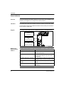
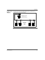
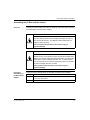
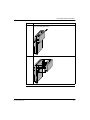
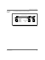
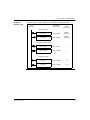
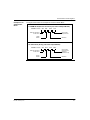
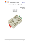
170 PNT Series
Modbus Plus Communication
Adapters
for Momentum
User Guide
31002940.0000
31002940
870 USE 103 00
Version 2.0
2
870 USE 103 00 May 2001
Table of Contents
About the Book . . . . . . . . . . . . . . . . . . . . . . . . . . . . . . . . . . . . . . . 5
Chapter 1
Introduction. . . . . . . . . . . . . . . . . . . . . . . . . . . . . . . . . . . . . . . . . . 7
At a Glance . . . . . . . . . . . . . . . . . . . . . . . . . . . . . . . . . . . . . . . . . . . . . . . . . . . . . . 7
Product Overview . . . . . . . . . . . . . . . . . . . . . . . . . . . . . . . . . . . . . . . . . . . . . . . . . 8
Status Indicators . . . . . . . . . . . . . . . . . . . . . . . . . . . . . . . . . . . . . . . . . . . . . . . . . 10
Address Switches . . . . . . . . . . . . . . . . . . . . . . . . . . . . . . . . . . . . . . . . . . . . . . . . 12
Ports and Cabling . . . . . . . . . . . . . . . . . . . . . . . . . . . . . . . . . . . . . . . . . . . . . . . . 15
Chapter 2
Assembling a Communications Adapter and I/O Base . . . . . . 17
At a Glance . . . . . . . . . . . . . . . . . . . . . . . . . . . . . . . . . . . . . . . . . . . . . . . . . . . . .
Connections Between the Adapter and I/O Base . . . . . . . . . . . . . . . . . . . . . . . .
Assembling the I/O Base and the Adapter . . . . . . . . . . . . . . . . . . . . . . . . . . . . .
Labeling the Assembled Module . . . . . . . . . . . . . . . . . . . . . . . . . . . . . . . . . . . . .
Disassembling an Adapter from an I/O Base . . . . . . . . . . . . . . . . . . . . . . . . . . .
Chapter 3
Using Modbus Plus for Distributed I/O Servicing . . . . . . . . . . 25
At a Glance . . . . . . . . . . . . . . . . . . . . . . . . . . . . . . . . . . . . . . . . . . . . . . . . . . . . .
Strategies for Distributed I/O Servicing . . . . . . . . . . . . . . . . . . . . . . . . . . . . . . . .
Network Configuration. . . . . . . . . . . . . . . . . . . . . . . . . . . . . . . . . . . . . . . . . . . . .
Modbus Plus Network Layouts . . . . . . . . . . . . . . . . . . . . . . . . . . . . . . . . . . . . . .
Chapter 4
17
18
19
21
23
25
26
27
28
How Communication Adapters Handle Messages . . . . . . . . . 31
At a Glance . . . . . . . . . . . . . . . . . . . . . . . . . . . . . . . . . . . . . . . . . . . . . . . . . . . . . 31
How Messages Are Defined in the Application . . . . . . . . . . . . . . . . . . . . . . . . . . 32
How Messages are Transacted. . . . . . . . . . . . . . . . . . . . . . . . . . . . . . . . . . . . . . 33
Chapter 5
Communication Access Registers . . . . . . . . . . . . . . . . . . . . . . 35
At a Glance . . . . . . . . . . . . . . . . . . . . . . . . . . . . . . . . . . . . . . . . . . . . . . . . . . . . .
Overview of Register Types . . . . . . . . . . . . . . . . . . . . . . . . . . . . . . . . . . . . . . . .
Data Registers. . . . . . . . . . . . . . . . . . . . . . . . . . . . . . . . . . . . . . . . . . . . . . . . . . .
Configuration Registers. . . . . . . . . . . . . . . . . . . . . . . . . . . . . . . . . . . . . . . . . . . .
Status Registers . . . . . . . . . . . . . . . . . . . . . . . . . . . . . . . . . . . . . . . . . . . . . . . . .
35
36
38
39
41
3
4
870 USE 103 00 May 2001
About the Book
At a Glance
Document Scope
This manual describes the functionality of the 170 PNT Series Modbus Plus
Communication Adapters.
The following information is an introduction to this manual:
Function: The Modbus Plus Communication Adapters can be connected to any
Momentum I/O base to create a functional I/O module.
The adapters provide direct connection to the Modbus Plus network, enabling a
programmable controller to communicate with field devices wired to the I/O base
terminals.
The controller on the network can read from the input terminals and write to the
output terminals of the I/O base using Modbus Plus Peer Cop or MSTR Function
Block messaging.
Data Format: Data bits are transferred in the IEC format. This is the standard data
format for the Momentum product line.
Models:
Model 170 PNT 110 20 has one Modbus Plus port for connection to a network with
a single trunk cable.
Model 170 PNT 160 20 has two ports for connection to either a single-cable or dualcable network.
Validity Note
870 USE 103 00 January, 2001
The data and illustrations found in this book are not binding. We reserve the right to
modify our products in line with our policy of continuous product development. The
information in this document is subject to change without notice and should not be
construed as a commitment by Schneider Electric.
5
Product Related
Warnings
Schneider Electric assumes no responsibility for any errors that may appear in this
document. If you have any suggestions for improvements or amendments or have
found errors in this publication, please notify us. No part of this document may be
reproduced in any form or by any means, electronic or mechanical, including
photocopying, without express written permission of the Publisher, Schneider
Electric.
User Comments
We welcome your comments about this document. You can reach us by e-mail at
[email protected]
6
870 USE 103 00 May 2001
Introduction
1
At a Glance
Purpose
This chapter gives an overview of the Momentum Modbus Plus Communication
Adapter models 170 PNT 110 20 and 170 PNT 160 20 and describes their status
indicators, address switches, ports and cabling.
What’s in this
Chapter?
This chapter contains the following topics:
Topic
Product Overview
870 USE 103 00 May 2001
Page
8
Status Indicators
10
Address Switches
12
Ports and Cabling
15
7
Introduction
Product Overview
Overview
This section provides an overview of the features and function of the Momentum
Modbus Plus Communication Adapters.
Function
The Modbus Plus Communication Adapters can be connected to any Momentum I/
O base to create a functional I/O module.
The adapters provide direct connection to the Modbus Plus network, enabling a
programmable controller to communicate with field devices wired to the I/O base
terminals.
The controller on the network can read from the input terminals and write to the
output terminals of the I/O base using Modbus Plus Peer Cop or MSTR Function
Block messaging.
Data Format
Data bits are transferred in the IEC format. This is the standard data format for the
Momentum product line.
Models
Model 170 PNT 110 20 has one Modbus Plus port for connection to a network with
a single trunk cable.
Model 170 PNT 160 20 has two ports for connection to either a single-cable or dualcable network.
Diagram
The diagram below shows a Modbus Plus Communication Adapter mounted on a
typical I/O base.
Side
View
Communication
Adapter
Front
View
I/O Base
Modbus Plus Port B
(170 PNT 160 20 only)
Modbus Plus Port A
(both models)
Communication
Adapter
I/O Base
8
870 USE 103 00 May 2001
Introduction
Environmental
Specification
870 USE 103 00 May 2001
The adapter conforms to the environmental specification for the I/O base upon which
it is mounted. For further information refer to the Momentum I/O Bases User
Manual, part number 870 USE 002 00.
9
Introduction
Status Indicators
Overview
This section describes the status indicators for each model, gives a diagram of the
indicators, and explains how to interpret the indicator patterns.
Indicators
Each model has a front panel indicator showing its network communication status.
The dual-cable model has two additional indicators which identify communication
errors on the two cable paths.
Diagram
The communication status and error indicators are shown in the diagram below
Modbus Plus
Communication Active
(Green)
(All models)
Communication Error
Channel A
(Red)
MB+
ACT
ERROR
A
(170 PNT 160 20 only)
B
7 8
5 6
7 8
0 1
23 4
9
(170 PNT 160 20 only)
5 6
Modbus Plus
Active Indicator
Patterns
0 1
23 4
9
Communication Error
Channel B
(Red)
The table below describes the status associated with each active indicator pattern.
Indicator Pattern (Green)
Status
Six flashes/second
Normal operating state. All nodes on a healthy
network flash this pattern.
One flash/second
The node is off-line. After being in this state for 5
seconds, the node attempts to go to its normal
operating state.
Two flashes, then OFF for 2 seconds
The node detects the network token being passed
among other nodes, but it never receives the token.
Three flashes, then OFF for 1.7
seconds
The node does not detect any token passing on the
network.
Four flashes, then OFF for 1.4 seconds The node has detected another node using the
same address.
10
870 USE 103 00 May 2001
Introduction
Modbus Plus
Channel Error
Indicators
870 USE 103 00 May 2001
Model 170 PNT 160 20 displays the following error indicator patterns:
Indicator (Red)
Status
Channel A Error
Communications error at network port A.
Channel B Error
Communications error at network port B.
11
Introduction
Address Switches
Overview
This section describes the address switches and explains how to use them to set the
module address.
Two Rotary
Switches
Each Modbus Plus Communication Adapter has two rotary switches on the lower left
portion of the front panel. These switches are used to set the Modbus Plus node
address.
Guidelines for
Node Addresses
Follow these guidelines when setting node addresses:
Addresses Must
Match
The node address is also defined in the Peer Cop Table and MSTR function blocks
of the user’s application program. The address defined in the application program
must match the one set by the adapter's front panel switches.
12
l
l
l
l
The node address should be assigned by your network administrator.
Each node must have a unique address in the range 1... 64.
Duplicate addresses are not allowed.
Addresses are assigned logically and are not dependent upon the physical
locations of the node devices.
l Starting at address 1, the lowest addresses should be assigned to programmable
controllers. Communication adapters should be assigned the next addresses in
direct sequence.
870 USE 103 00 May 2001
Introduction
Example of Node
Address
Assignment
The figure below shows typical address assignments for a network with one
controller and four communication adapters.
Node 1
Programmable Controller
with Modbus Plus Port
(Assigned Node Address 1)
Node 3
Node 5
Modbus Plus
Communication
Adapters
Node 4
Node 2
with
I/O Bases
870 USE 103 00 May 2001
13
Introduction
Setting the
Switches
The figure below illustrates how to set a Modbus Plus Node Address.
Do not install any adapter unless you have set
its Modbus PLus address for your application.
MB+
ACT
ERROR
A
B
9
0 1
8
2
7
3
X10
4
5 6
9
0 1
8
2
7
3
4
X1
5 6
X10
9
0 1
8
2
7
3
5 6
9
4
X1
0 1
8
2
See your network
administator to get
the node address for
each adapter.
7
3
Node
Upper
Address Switch
1... 9
0
10... 19
1
20... 29
2
30... 39
3
40... 49
4
50... 59
5
60... 64
6
Lower
Switch
1... 9
0... 9
0... 9
0... 9
0... 9
0... 9
0... 4
4
5 6
This example sets the address to 31.
14
870 USE 103 00 May 2001
Introduction
Ports and Cabling
Overview
This section provides information about ports and cabling for the Momentum
Modbus Plus Communication Adapters.
Ports
Model 170 PNT 110 20 has one Modbus Plus port for connection to a network with
a single trunk cable.
Model 170 PNT 160 20 has two ports for connection to either a single-cable or dualcable network.
Cabling
870 USE 103 00 May 2001
Network port connections are compatible with standard Modbus Plus drop cables.
Drop cables are available from Schneider Automation in three standard lengths:
2.4m (8ft), 3m (10ft), and 6m (20ft).
15
Introduction
16
870 USE 103 00 May 2001
Assembling a Communications
Adapter and I/O Base
2
At a Glance
Purpose
This chapter explains how a Communication Adapter connects with an I/O base,
how to assemble a module, and how to label the assembled module. It also includes
a procedure for disassembling a module.
What’s in this
Chapter?
This chapter contains the following topics:
Topic
Connections Between the Adapter and I/O Base
870 USE 103 00 May 2001
Page
18
Assembling the I/O Base and the Adapter
19
Labeling the Assembled Module
21
Disassembling an Adapter from an I/O Base
23
17
Assembling Adapter and I/O Base
Connections Between the Adapter and I/O Base
Overview
This section explains the connections between a Communication Adapter and an I/
O base.
Physical
Connections
A Communication Adapter can be snapped directly onto a Momentum I/O base,
making connections at three points:
l The plastic snap extensions on the two sides of the adapter unit fit into the two
slots on the sides of the I/O base
l The ATI connectors on the two units mate together
Clips lock the adapter in place. The clips can be released with a common
screwdriver to remove the adapter.
Electrical
Connections
Each adapter connects to the internal communication connector of its I/O base. The
adapter receives its operating voltage from the I/O base through this internal
connection.
The adapter monitors its voltage and goes offline to the Modbus Plus network if the
voltage is not within tolerance.
18
870 USE 103 00 May 2001
Assembling Adapter and I/O Base
Assembling the I/O Base and the Adapter
Overview
This section contains safety precautions for handling components and a procedure
for assembling an I/O base and an adapter.
CAUTION
ADAPTER MAY BE DAMAGED BY STATIC ELECTRICITY
Use proper ESD procedures when handling the adapter, and do not
touch the internal elements. The adapter’s electrical elements are
sensitive to static electricity.
Failure to observe this precaution can result in injury or
equipment damage.
CAUTION
ELECTRICAL CIRCUITRY MAY BE EXPOSED
Electrical circuitry on the I/O base may be exposed when a Momentum
adapter is not mounted. Make sure that the I/O base is not under power
when it does not have an adapter mounted on it. To make sure that
power is not present, do not insert the wiring connectors to the I/O base
until after the adapter has been mounted.
Failure to observe this precaution can result in injury or
equipment damage.
Procedure:
Assembling an
I/O Base and an
Adapter
870 USE 103 00 May 2001
Follow the steps in the table below to assemble an I/O base and an adapter.
Step
Action
1
Choose a clean environment to assemble the I/O base and adapter to protect the
circuitry from contamination.
2
Make sure that the I/O base is not under power when you assemble the module.
19
Assembling Adapter and I/O Base
Step
20
Action
3
Align the two plastic snap extensions on the Adapter with the slots on the sides
of the I/O base. The ATI connectors will automatically line up when the units are
in this position. The two devices should be oriented such that their
communication ports are facing out on the back side of the assembly.
4
Using the sidewalls of the I/O base as guides, carefully push the Adapter onto
the base until the extensions snap into place. The ATI connectors on the two
units will be mated to each other in the process.
870 USE 103 00 May 2001
Assembling Adapter and I/O Base
Labeling the Assembled Module
Overview
A front panel label is supplied with each I/O base. The user should fill out the label
and affix it to the front panel of the adapter.
What Goes on
the Label?
The user should fill out the label to identify the field wiring connections and
application of the I/O base terminals.
Example of a
Label
A fill-in label is illustrated in the diagram below. The numbered pointers in the
diagram refer to the descriptions in the table that follows.
1
Plant
Station
Addr.
MODICON
TSX Momentum
Telemecanique
6
170 ADM 350 10
2
4
7
1
2 3
4 5
6 7
8
24 VDC IN-16PT
9 10 11 12 13 14 15 16 24 VDC OUT-16PT
3
5
The following table describes the numbered pointers above.
Where Does the
Label Go?
870 USE 103 00 May 2001
No.
Description
1
Fields for plant name, station name and network address
2
Cutout–the model number of the Adapter shows through
3
Model Number of the I/O base
4
Color code of the I/O base
5
Short description of the I/O base
6
Field for the symbol name of inputs
7
Area for the symbol name of outputs
The label should be affixed to the front panel of the adapter in such a way that the
cutout area above the I/O model number allows the pre-screened model number of
the adapter to show through.
21
Assembling Adapter and I/O Base
Disassembling an Adapter from an I/O Base
Overview
This section contains safety precautions and a procedure for disassembling an
adapter from an I/O base.
CAUTION
ELECTRICAL CIRCUITRY MAY BE EXPOSED
Before removing an adapter from the base, disconnect the wiring
connectors. Make sure that the I/O base is not under power when it
does not have a Momentum adapter mounted on it.
Failure to observe this precaution can result in injury or
equipment damage.
Tools Required
A flat-head screw driver may be needed to disassemble the unit.
Disassembling
an Adapter from
an I/O Base
Follow the steps in the table below to remove an adapter from an I/O base.
22
Step
Action
1
Choose a clean environment to disassemble the unit, in order to protect the
circuitry from contamination.
2
Make sure that the I/O base is not under power by removing the terminal
connectors from the I/O base.
870 USE 103 00 May 2001
Assembling Adapter and I/O Base
Step
870 USE 103 00 May 2001
Action
3
Use a screwdriver to push the clips on both sides of the adapter inward, as
shown in the illustration below.
4
Lift off the adapter.
23
Assembling Adapter and I/O Base
24
870 USE 103 00 May 2001
Using Modbus Plus for Distributed
I/O Servicing
3
At a Glance
Purpose
This chapter explains how best to configure a network for efficient servicing of
distributed I/O.
What’s in this
Chapter?
This chapter contains the following topics:
Topic
Strategies for Distributed I/O Servicing
870 USE 103 00 May 2001
Page
26
Network Configuration
27
Modbus Plus Network Layouts
28
25
Modbus Plus for DIO Servicing
Strategies for Distributed I/O Servicing
Overview
Modbus Plus networks can be used to service multi-purpose control applications, or
they can be organized for the most efficient servicing of distributed I/O devices. This
section compares the two approaches.
Network
Function
In multi-purpose control applications, the network is designed to allow
communication between in programmable controllers, operator interfaces, and other
kinds of devices.
For efficient servicing of distributed I/O, the network is designed to allow
communication between one programmable controller and a group of I/O modules.
Message Timing
In multi-purpose control applications, timing can vary according to the current
processing requirements of each node’s internal program.
In efficient distributed I/O servicing applications, the timing of message transactions
must be predictable to allow deterministic timing of the I/O control process.
Size
In general applications, up to five networks can be joined by Bridge Plus devices to
extend the cable length to 2250 m (7500ft) and the node count to 320 nodes.
In distributed I/O applications, messages are transacted on the local network only.
BridgePlus devices are not applicable to networks used for distributed I/O.
Recommendation
26
Multi-purpose networks are not recommended for servicing I/O control applications
in which I/O timing must be deterministic.
870 USE 103 00 May 2001
Modbus Plus for DIO Servicing
Network Configuration
Overview
This section contains guidelines for configuring a Modbus Plus network for
distributed I/O servicing.
Limit Types of
Devices on
Network
To ensure deterministic timing, the network should consist of just one programmable
controller node and the required group of I/O nodes.
Maximum
Configuration
The table below summarizes the Modbus Plus network’s maximum configuration for
a distributed I/O application consisting of Momentum products.
Non-I/O devices, such as additional controllers, programmers, or operator
interfaces, should communicate with the I/O network controller through a separate
Modbus Plus network or other type of connection.
Parameter
870 USE 103 00 May 2001
Specification
max. number of nodes
64 including Controller
max. distance between two nodes
450 m (1500ft)
min. distance between two nodes
3 m (10ft)
max. length of network
450 m (1500ft)
max. number of data words (16-bit words)
500 input, 500 output
max. number of I/O points (16 bits/word)
8000 input, 8000 output
27
Modbus Plus for DIO Servicing
Modbus Plus Network Layouts
Overview
This section provides two examples of Modbus Plus network layouts using
communication adapters in a distributed I/O control application.
Note that only one programmable controller and the required I/O nodes are present
in this kind of application.
Single Cable
Example
The figure below illustrates a single cable configuration.
Node 1
Programmable
Controller
with
Modbus Plus
Port
Network Trunk Cable
Tap
Drop Cable
Node 3
Node 5
170 PNT 110 20
Node 4
Node 2
with
I/O bases
I/O field device wiring
28
870 USE 103 00 May 2001
Modbus Plus for DIO Servicing
Dual Cable
Example
The example below illustrates a dual cable configuration.
Network Trunk Cable A
Network Trunk Cable B
Node 1
870 USE 103 00 May 2001
Programmable
Controller
with
Modbus Plus
Redundant
Network
Option Adapter
Node 2
Node 3
170 PNT 160 20
with
I/O bases
29
Modbus Plus for DIO Servicing
30
870 USE 103 00 May 2001
How Communication Adapters
Handle Messages
4
At a Glance
Purpose
This chapter describes how messages are defined in the application and how
messages are transacted on the network.
What’s in this
Chapter?
This chapter contains the following topics:
870 USE 103 00 May 2001
Topic
Page
How Messages Are Defined in the Application
32
How Messages are Transacted
33
31
Communication Adapter Message Handling
How Messages Are Defined in the Application
Overview
This section describes where and how messages are defined in the application.
Peer Cop Table
The user defines I/O message transactions in the Peer Cop table of the controller.
Entries to the table are made using panel software, such as Schneider’s Concept or
Modsoft software.
The Peer Cop table specifies the controller registers that are to be used for the I/O
data storage. It also specifies the Communication Adapter node addresses which
will handle that data.
MSTR Blocks
I/O data messages can also be transacted using Modbus Plus MSTR function
blocks in the controller’s application program.
Addresses Must
Match
Principle: The address defined for each adapter in the Peer Cop table and in MSTR
blocks must be identical to the address switch settings on the front panel of the
adapter.
Mapping Data to
I/O Bases
Mapping of data between the controller’s data registers and the field terminals of I/
O bases is unique to each model of I/O base. Mapping is described in the
Momentum I/O Bases User Manual, part number 870 USE 002 00.
32
870 USE 103 00 May 2001
Communication Adapter Message Handling
How Messages are Transacted
Overview
This section explains how a Communication Adapter relays information between its
I/O base and a programmable controller.
The Right to
Transmit
A token frame is passed from node to node in a rotating address sequence. The
node currently holding the token has the sole right to transmit. All other nodes
monitor the network and extract messages addressed to them.
Messages from
Communication
Adapters
When a Communication Adapter at an input base module acquires the token, it
transmits its message to the programmable controller node. The message data
describes the current states of the signals at the base’s field input terminals.
The controller reads the message and steers its contents into the data registers
defined for that adapter’s address in the controller’s Peer Cop table.
Messages to
Communication
Adapters
When the programmable controller acquires the token, it transmits its messages to
the Communication Adapters. Messages are sent to the node addresses defined in
the controller’s Peer Cop table, with the message contents taken from the data
registers defined in the table.
Each Communication Adapter at an Output base module uses its received message
to control the field devices connected to the base’s output terminals.
870 USE 103 00 May 2001
33
Communication Adapter Message Handling
34
870 USE 103 00 May 2001
Communication Access Registers
5
At a Glance
Purpose
This chapter describes the three types of communication access registers.
What’s in this
Chapter?
This chapter contains the following topics:
870 USE 103 00 May 2001
Topic
Page
Overview of Register Types
36
Data Registers
38
Configuration Registers
39
Status Registers
41
35
Communication Access Registers
Overview of Register Types
Purpose
Each adapter contains three groups of internal registers that enable the application
program to communicate with the I/O base module.
This section describes the three register types, their functions and how they are
accessed.
Register Types
The three types of internal registers are:
l Data registers
l Configuration registers
l Status registers
Functions
The application can access the registers through the network to transfer input or
output data at the module’s field terminals, to set or retrieve the module’s
configuration, or to monitor its status.
Access to
Registers
The registers are accessed as 4XXXX references in a controller’s application
program. Note that the Data Registers are the only ones that can be accessed by
the controller’s Peer Cop table. All of the registers can be accessed by MSTR
function blocks.
36
870 USE 103 00 May 2001
Communication Access Registers
Diagram of
Register Types
The three groups of internal registers are illustrated in the diagram below.
MODBUS
PLUS
NETWORK
STARTING
REFERENCE
(Hex / Decimal)
LENGTH
(16-Bit Words)
DATA REGISTERS
DATA INPUT
(Read Only)
40001 / 400001
Module
dependent
DATA OUTPUT
(Write Only)
40001 / 400001
Module
dependent
MODULE TIMEOUT
(Read or Write)
4F001 / 461441
1
MODULE OWNERSHIP
(Read or Write)
4F401 / 462465
CONFIGURATION REGISTERS
3
STATUS REGISTERS
870 USE 103 00 May 2001
MODULE STATUS
(Read Only)
4F801 / 463489
12
MODULE ASCII HEADER
(Read Only)
4FC01 / 464513
1... 32
37
Communication Access Registers
Data Registers
Overview
This section describes the use, field length and access to data registers.
Use
Starting reference 40001 (hex) is used to address input data from field inputs and
output data to field outputs.
Field Length
The data field length is determined by the specific I/O base.
Access
This reference is the only one that is accessible through Peer Cop data transfers.
All other registers can be accessed using MSTR blocks.
38
870 USE 103 00 May 2001
Communication Access Registers
Configuration Registers
Overview
This section describes the function and parameters for module timeout and module
ownership registers.
Module Timeout
Register
Function
The module timeout register specifies the amount of time that outputs will be held in
their current state, if they are not updated by a new Modbus Plus Write command.
If the module’s holdup time expires before a new write command is received, all
outputs are set to logical 0 (zero).
Module Timeout
Register
Parameters
The table below gives the parameters for module timeout registers:
Module
Ownership
Registers
Function
Parameters
Sharing Reference
4F001 (hex)
Field Length
1 word
Access
Modbus Plus Read command
Units
1 = 10 milliseconds
Minimum Value
30 (300 milliseconds)
Maximum Value
6000 (60 seconds)
Default Value
100 (1 second)
Module ownership registers specify the addresses of up to three nodes which may
concurrently own write privilege to the adapter.
When the adapter first receives power, it will give sole write privilege to the first node
that writes to it. The adapter maintains an internal 60-second timer for handling the
write privilege, and will reserve sole privilege to that node as long at the node
continues to write within 60-second intervals to the adapter.
A node which currently owns the write privilege may write up to three words to the
adapter starting at reference 4F401. Each of the three words must correspond to a
valid node address in the range 1...64 decimal. With those addresses stored in the
adapter, any of those three nodes may then write to the adapter. This allows up to
three nodes to concurrently own write privilege to the adapter.
If writes continue to occur within the 60-second interval from any of the three
privileged nodes, no other node may write to the adapter. If the timer is allowed to
expire, any node may write to the adapter.
870 USE 103 00 May 2001
39
Communication Access Registers
Note that this 60-second Write Privilege timer is separate from the Outputs Holdup
timer, and applies only to the write privilege. Any node may read the input data or
status information from the adapter. The 60-second time is a fixed value and is not
accessible to the application.
Module
Ownership
Registers
Parameters
40
The table below contains parameters for module ownership registers.
Parameters
Starting Reference
4F401 (hex)
Field Length
3 words
870 USE 103 00 May 2001
Communication Access Registers
Status Registers
Overview
This section describes the function and parameters of the module status block and
the ASCII header block.
Module Status
Block Function
These registers provide information about the module’s revision level and current
operating parameters.
Module Status
Block
Parameters
The module status block layout is described in the table below. The registers can
be read, but cannot be written into.
870 USE 103 00 May 2001
Reference
(hex)
Purpose
Contents
4F801
Length of status block (words)
12 decimal
4F802
I/O module quantity of input bytes Module dependent
4F803
I/O module quantity of output
bytes
Module dependent
4F804
I/O module ID number
Module dependent
4F805
I/O module revision number
Format: XRwhere:X = upper 4 bits,
always 0000R = lower 12 bits, defining the
revision as 3 hex characters.Example:
100 hex = Rev. 1.00 200 hex = Rev. 2.00
4F806
ASCII header block length (words) Module dependent
4F807
Last node address to
communicate
1...64 decimal
4F808
Remaining ownership reservation
time
30...6000 decimal, in units of 10 ms (300
ms...60 s)
4F809
Remaining outputs holdup time
30...6000 decimal, in units of 10 ms (300
ms...60 s)
4F80A
I/O module health
8000 hex = healthy0000 hex = not healthy
4F80B
I/O module last error value
Module dependent
4F80B
I/O module error counter
Error count 0000...FFFF hex
41
Communication Access Registers
ASCII Header
Block Function
These registers contain an ASCII text description of the module.
ASCII Header
Block
Parameters
The block length depends upon the type of I/O base to which the adapter is
connected. The maximum length is 64 bytes of ASCII characters, corresponding to
a length of 8...32 words as specified in word 6 of the module status block (at
reference 4F806).
The registers can be read, but cannot be written into.
The following table shows the header block layout as a string of ASCII characters as
they are positioned from the starting reference 4FC01.
42
4FC01+Byte
Offset
ASCIICharacters
0...10
MODBUS PLUS
Modbus Plus network device
11
20 hex (32 decimal)
space
12
20 hex (32 decimal)
space
13 14 15
IEC
IEC data mode (Data bit order per IEC standard)
16
20 hex (32 decimal)
space
17 18 19
DIGEXPANA
Digital module (ID range: XX00...XX7F hex)Expert
module (ID range: XX80...XXBF hex)Analog module
(ID range: XXC0...XXFE hex)
Meaning
20 21
HHLL
Module ID code(HH = high byte, LL = low byte)
22 23
I I OO
Module I/O words(I I = input words, OO = output
words)
24...63
--
Reserved
870 USE 103 00 May 2001
Communication Access Registers
Examples of an
ASCII Header
Block
The figure below shows two examples of an ASCII Header Block.
170 ADM 350 00 (Discrete 16-Point Input, 16-Point Output Module)
MODBUS PLUS
984
DIG
0002
0101
Data bits transferred
in 984 format
Input words: 1
Output words: 1
Digital
module
Module ID
170 AAO 120 00 (Analog 4-Channel Output Module)
MODBUS PLUS
Data bits transferred
in 984 format
Analog
module
870 USE 103 00 May 2001
984
ANA
01C3
0005
Input words: 0
Output words: 5
(includes 1
parameter word)
Module ID
43
Communication Access Registers
44
870 USE 103 00 May 2001