1
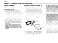
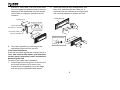
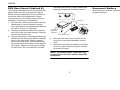
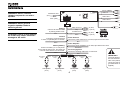
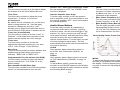
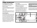
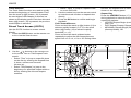
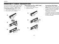
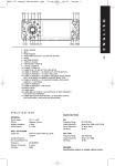
UV8035
Owner's Manual
Multimedia Receiver
UV8035
UV8035
PREPARATION
Getting Started
Installation Requirements
Speaker Requirements
It’s a good idea to read all of the instructions
before beginning the installation.
This unit is designed for installation in cars,
trucks and vans with an existing radio opening.
In many cases, a special installation kit will be
required to mount the radio to the dashboard.
These kits are available at electronics supply
stores and car stereo specialty shops. Always
check the kit application before purchasing to
make sure the kit works with your vehicle. If you
need a kit but cannot locate one, call our
customer support line at 1-800-323-4815.
(U.S.A. and Canada only.)
Only connect speakers rated with a load
impedance of 4 ohms. Speakers with a load
impedance of less than 4 ohms could damage
the unit.
Contents
Preparation................................................ 2
Installation Instructions.............................. 3
Wiring ........................................................ 6
Detachable Control Panel ......................... 7
Remote Control ......................................... 8
Operating Instructions ............................. 10
Tuner Operation ...................................... 15
CD/DVD Operation.................................. 16
Memory Card Operation.......................... 19
Dual Zone Operation ............................... 20
System Setup Menu ................................ 21
Care and Maintenance ............................ 23
Specifications .......................................... 24
Tools and Supplies
The following tools and supplies are needed to
install the radio.
•
•
•
•
•
•
•
•
•
Torx type, flathead and Philips screwdrivers
Wire cutters and strippers
Tools to remove existing radio (screwdriver,
socket wrench set or other tools)
Electrical tape
Crimping tool
Volt meter/test light
Crimp connections
18 gauge wire for power connections
16-18 gauge speaker wire
2
Toll-Free Installation Assistance
If you require assistance, contact Technical
Support at 1-800-323-4815 from 8:30 a.m. to
7:00 p.m. EST Monday through Friday and from
9:00 a.m. to 5:00 p.m. EST on Saturday.
(U.S.A. and Canada only.)
UV8035
INSTALLATION INSTRUCTIONS
Before You Begin
DIN Front Mount (Method A)
1. Disconnect battery negative terminal.
2. Remove transport screws.
1. Slide the mounting sleeve off of the chassis
if it has not already been removed. If it is
locked into position, use the removal keys
(supplied) to disengage it. The removal
keys are depicted in “Removing the Unit”.
2. Check the dashboard opening size by sliding the mounting sleeve into it. If the opening is not large enough, carefully cut or file
as necessary until the sleeve easily slides
into the opening. Do not force the sleeve
into the opening or cause it to bend or bow.
Check that there will be sufficient space
behind the dashboard for the radio chassis.
Important Notes
•
•
•
•
•
•
Before final installation, test the wiring
connections to make sure the unit is
connected properly and the system works.
Use only the parts included with the unit to
ensure proper installation. The use of
unauthorized parts can cause malfunctions.
Consult with your nearest dealer if
installation requires the drilling of holes or
other modifications to your vehicle.
Install the unit where it does not interfere
with driving and cannot injure passengers if
there is a sudden or emergency stop.
If the installation angle exceeds 30º from
horizontal, the unit might not give optimum
performance.
Avoid installing the unit where it will be
subject to high temperatures from direct
sunlight, hot air, or from a heater, or where
it would be subject to excessive dust, dirt or
vibration.
4.
5.
6.
Dashboard
Bend Tabs
182
7.
53
Screw Stud
8.
3. Locate the series of bend tabs along the
top, bottom and sides of the mounting
sleeve. With the sleeve fully inserted into
3
the dashboard opening, bend as many of
the tabs outward as necessary to firmly
secure the sleeve to the dashboard.
Place the radio in front of the dashboard
opening so the wiring can be brought
through the mounting sleeve.
Follow the wiring diagram carefully and
make certain all connections are secure
and insulated with crimp connectors or
electrical tape to ensure proper operation.
After completing the wiring connections,
turn the unit on to confirm operation (vessel
accessory switch must be on). If the unit
does not operate, recheck all wiring until
the problem is corrected. Once proper
operation is achieved, turn the accessory
switch off and proceed with final mounting
of the chassis.
Carefully slide the radio into the mounting
sleeve making sure it is right-side-up until it
is fully seated and the spring clips lock it
into place.
Attach one end of the perforated support
strap (supplied) to the screw stud on the
rear of the chassis using the hex nut and
spring washer provided. Fasten the other
end of the perforated strap to a secure part
of the dashboard either above or below the
radio using the screw and plain washer provided. Bend the strap, as necessary, to
UV8035
position it. CAUTION: The rear of the radio
must be supported with the strap to prevent
damage to the dashboard from the weight
of the radio or improper operation due to
vibration.
2. Insert the removal keys straight back until
they click, and then pull the radio out. If
removal keys are inserted at an angle, they
will not lock properly to release the unit.
Dashboard
Dashboard
Support Strap
Plain Washer
Screw (5 x 25mm)
Hex Nut (5mm)
Screw Stud
Spring Washer
Removal Key
9. Test radio operation by referring to the
operating instructions for the unit.
Trim Plate Installation
Push the trim plate against the chassis until it is
fitted. You must do this before you install the
control panel, otherwise it can't be attached.
Removing the Unit
To remove the radio after installation:
1. Insert fingers into the groove on the front of
the frame and pull out to remove the
frame.(when re-attaching, point the edge
with the groove downward and attach)
4
UV8035
DIN Rear Mount (Method B)
This unit has threaded holes in the chassis side
panels which may be used with the original
factory mounting brackets of some vehicles to
mount the radio to the dashboard. Please
consult with your local mobile stereo shop for
assistance on this type of installation.
1. Remove the existing factory radio from the
dashboard or center console mounting.
Save all hardware and brackets as they will
be used to mount the new radio.
2. Carefully unsnap the plastic trim ring from
the front of the new radio chassis. Remove
and discard the trim ring.
3. Remove the factory mounting brackets and
hardware from the existing radio and attach
them to the new radio. Select a position
where the screw holes of the bracket and
the screw holes of the main unit are aligned
(are fitted). Tighten the screws at 2 places
on each side. Do not exceed M5 x 9 MM
maximum screw size. Longer screws may
damage components inside the chassis.
Screws
Dashboard
Factory
Mounting
Bracket
Hook (Remove)
4. Wire the new radio to the vehicle as outlined in the Universal Installation instructions.
5. Mount the new radio assembly to the dashboard or center console using the reverse
procedure of step 1.
NOTE: The mounting box, outer trim ring,
and half-sleeve are not used for method B
installation.
5
Reconnect Battery
When wiring is complete, reconnect the battery
negative terminal.
UV8035
WIRING
WARNING! Never combine
(bridge) outputs for use with 1
speaker.
Subwoofer Out
Aux-In (Black)
R (Red)
Video In
L (White)
(Yellow)
(Blue)
Video Out 1
Fuse (15A)
Video Out 2
WARNING! Never ground
negative speaker leads to
chassis ground.
CAUTION: Failure to wire exactly
as shown may cause electrical
damage to the radio.
Parking
Connect to switched side
of parking brake circuit.
Rear Line out
R (Red)
Gray
L (White)
Frontr Line out
R (Red)
Black
L (White)
Pink
Ground
Connect to ground terminal
or clean, unpainted part of chassis.
Blue
Memory/Battery
Connect to battery or 12 volt power
source that is always live. The radio will
not work if this wire is not connected.
Power Amplifier
Connect to power amplifier. If not used, tape bare end of wire.
Blue/White
Accessory/Ignition
Connect to existing radio wire or radio fuse.
Yellow
Red
FRONT SP
White
Left Speaker
(Front)
Gray/Black
Stripe
(Yellow)
Power Antenna
Connect to power antenna. If not used, tape bare end of wire.
Black
White/Black
Stripe
(Yellow)
Gray
REAR SP
Green/Black
Stripe
Right Speaker
(Front)
Green Purple/Black
Stripe
Left Speaker
(Rear)
6
Purple
Right Speaker
(Rear)
IMPORTANT!
The pink parking wire MUST
be connected to the switched
side of the parking break
circuit (the part that becomes
grounded when the brake is
applied).
UV8035
DETACHABLE CONTROL PANEL
•
•
•
•
•
•
•
•
•
DO NOT insert the control panel from the
left side. Doing so may damage it.
Do not put pressure on the display or
control buttons when handling the front
panel.
Do not touch the electrical terminals on the
front panel or main unit.
Remove dirt or foreign substances with a
clean, dry cloth only.
Do not expose the front panel to extreme
temperatures or direct sunlight.
Keep volatile agents such as benzene,
thinner or insecticides away from the front
panel.
Do not disassemble the front panel.
When taking the front panel with you,
please use the supplied carrying case to
protect the panel from dirt and damage.
Make sure there is no dust or dirt on the
electrical terminals on the back of the panel
as this could cause intermittent operation or
other malfunctions.
Removing the Control Panel
The front panel release button (3) releases the
mechanism that holds the front panel to the
chassis. To detach the front panel, perform the
following steps:
1. Turn the power off.
2. Press the release button.
3. Grasp the left side to release the front panel
and then pull it an an angle to remove the
right side from the chassis.
4. Store the front panel it in the supplied carrying case to protect it from dirt and damage
and take it with you to prevent theft.
Attaching the Control Panel
Before re-attaching the front panel, make sure
the electrical terminals on the back of the panel
are free of dust and dirt, as debris could cause
intermittent operation or other malfunctions.
To attach the front panel:
1. Insert the right side of the control panel into
the main unit, making sure the panel is
attached at the T-joint (see diagram).
2. Push the left side of the control panel near
the middle until a “click” sound is heard.
Release
Button
1.
2.
Control Panel
PUSH
7
UV8035
REMOTE CONTROL
The remote control will allow you to control the
advanced functions of the UV8035.
9
12
MUTE
1
2
10
8
5
15
MODE
4
11
VOLUME
16
6
17
13
3
14
AUDIO
18
30
37
34
31
19
38
20
21
GOTO
35
39
22
24
36
32
25
7
OFF
N
ME U
2-ZONE
DISPLAY
ON
27
+10
33
40
29
23
28
26
1.
2.
3.
4.
5.
6.
MUTE/Power
Open/Close/Eject
Audio Menu
Mode (select playing source)
Volume Up
Volume Down
7. Multi-Zone On/Off
8. Tune Up/Fast Forward
9. Tune Down/Fast Reverse
10. Left
11. Right
12. Up
13. Down
14. Seek Up
• Radio Tune
• Track Up
• File Up
• Next
15. Seek Down
• Radio Tune
• Track Down
• File Down
• Back
16. OK/Enter
17. Play/Pause
18. Stop/Return
19. 1
• Tuner M1 recall, Memory 1
• Track Number Entry
• File Number Entry
20. 2
• Tuner M2 recall, Memory 2
• Track Number Entry
• File Number Entry
21. 3
• Tuner M3 recall, Memory 3
8
• Track Number Entry
• File Number Entry
22. 4
• Tuner M4 recall, Memory 4
• Track Number Entry
• File Number Entry
23. 5
• Tuner M5 recall, Memory 5
• Track Number Entry
• File Number Entry
24. 6
• Tuner M6 recall, Memory 6
• Track Number Entry
• File Number Entry
25. 7/SUB-W
• Track Number Entry
• File Number Entry
• Subwoofer ON/OFF
26. 8
• Track Number Entry
• File Number Entry
27. 9/iX-BASS
• Track Number Entry
• File Number Entry
• iX-Bass ON/OFF/Adjust
28. 0/BAND
• Track Number Entry
• File Number Entry
• Change Band (3 FM, 2 AM)
UV8035
29. Press repeatedly to select a number in the
tens position for direct track entry (for
example, to select track “44”, press the +10
button four times and then press the 4 button).
30. DVD MENU/PBC
• DVD Menu
• PBC (for VCD 2.0 and up)
31. SET UP Menu (Disc only)
32. REPEAT
33. ZOOM
34. DVD OSD (On Screen Display)
35. GOTO (direct entry)
36. SUBTITLE (DVD)
37. DVD TITLE
38. DVD AUDIO
• DVD Audio
• VCD Audio L/R/ST
39. ANGLE (DVD only)
40. DISPLAY/MENU
Operating Range
The head unit remote
control sensor (22) is
located on the right side
of the control panel.
The remote control can
operate within a
distance of 3~5m of this
sensor.
Replacing the Battery
REMOTE SENSOR
When the range of operation of the card remote
control becomes short or stops functioning,
replace the battery with a new lithium battery.
Be sure to observe the proper polarity, as
indicated below.
(CR 2025)
1
9
2
UV8035
OPERATING INSTRUCTIONS
Power On/Off
Press and hold the
(power/mute) button (1)
or short press any other button on the control
panel (except open/eject) to turn the unit on.
Press and hold the power/mute button again to
turn the unit off.
NOTE: It is a characteristic of LCD panels
that, if subjected to cold temperatures for an
extended period of time, they may take
longer to illuminate than under normal
conditions. In addition, the visibility of the
numbers on the LCD may slightly decrease.
The LCD read-out will return to normal when
the temperature inside the vehicle increases
to a normal range.
display. Press the power/mute button again to
restore audio output to the previous level.
Mode Selector (MODE)
Press this MODE button (9) to select a different
mode of operation, as indicated on the display
panel. Available modes include TUNER, DISC,
CARD (SD), AV IN 1, AV IN 2.
AV IN/OUT Connector
Use the AV IN/OUT connector (21) to connect a
portable media device for playback through the
vehicle sound system.
Volume Control
Turn the rotary encoder (4) to increase/
decrease the volume level, shown on display
panel, from “00” to “46”. The display will
automatically return to the normal indication 5
seconds after the last volume adjustment or
when another function is activated.
1
Left Audio
2
Right Audio
Ground
Video
3
4
3.5mm A/V Cable ( not included )
See “AV Connector” on page 12 to learn how to
reverse the AV IN/OUT connector from IN to
OUT.
Mute
Press the power/mute ( ) button (1) to mute
the audio output “MUTE”appears on the
10
NOTE: For iPod or Zune video playback,
please refer to owner's manual that came
with your device. Please complete any
photo or video setting adjustments before
connecting the device to this unit.
UV8035
Display Selector (D)
System Menu (D/MENU)
You can change the way playback information
is displayed to suit your needs. Press the D/
DISP button (7) to alternate between the File
Menu and Elapsed Time interface screens,
shown below:
Press and hold the D/MENU button (7) for more
than 3 seconds to display the system menu.
You can then press the D/MENU button
repeatedly or press the tune/track |||< or >|||
buttons (18, 19) to access menu items.
Use the rotary encoder (4) to adjust the settings
for a selected function. The display will return to
the normal indication 5 seconds after the last
adjustment or when another function is
activated.
Angle
Turn the rotary encoder to adjust the angle of
the front panel upward by choosing a setting
from “00” to “12”.
Contrast
Turn the rotary encoder to adjust the screen
contrast from “00” to “50”.
Bright
Turn the rotary encoder to adjust the screen
brightness from “00” to “50”.
Color
Turn the rotary encoder to adjust the screen
color level from “00” to “50”.
Date Set
Turn the rotary encoder to adjust the DATE/
MONTH/YEAR. Press the rotary encoder (4) to
confirm each entry and move to the next field.
File Menu Interface
3
10 11
9 18 19
2
8
12
13
Elapsed Time Interface
4
22
6
21
14
UV8035
1
15 16 5
11
7 17
20
UV8035
Clock
Turn the rotary encoder (4) to the right to adjust
the minutes or to the left to adjust the hour.
speaker “OFF” when using headphones. When
the rear speaker is “OFF”, the “FADER” audio
function is disabled.
Time Form
Turn the rotary encoder to adjust the clock
format from “12 Hours” to “24 Hours”.
Internal Amplifier (Inter Amp)
Turn the rotary encoder to turn the system’s
built in amplifier on/off. It is recomended to turn
the internal amplifier “OFF” when connected to
an external amplifier.
AV Connector
By default, the AV connector (21) on the front
panel is designated as “IN”. Use the rotary
encoder to change the source to “OUT”,
allowing you to output the audio/video source
from the built-in DVD player to another device.
Tuner Set (Local/Distant)
Turn the rotary encoder to choose “Local” or
Distance”. Local mode favors access to local
stations whose signals are much stronger.
Tuner Area
Turn the rotary encoder to choose the
appropriate frequency spacing for your area:
U.S.A., Latin, Europe, or Orit (Russia).
Beep Tone
Turn the rotary encoder to choose whether and
audible beep is heard when a function is
selected: “BEEP ON” or “BEEP OFF”.
Programmable Turn-On Volume (Vol PGM)
Turn the rotary encoder to select the default
turn-on volume level. “VOL PGM 12” is the
default setting.
Rear Speaker On/Off (Rear Spk)
Turn the rotary encoder to turn the rear speaker
on/off. It is recommended to turn the rear
Audio Menu Button
Press the rotary encoder (4) repeatedly to
access the Audio Menu functions, including
sub-menu items. Use the tune/track |||< or >|||
buttons (18, 19) to cycle through only the toplevel menu functions, and then press the rotary
encoder to select the various adjustment
options for that feature. Turn the rotary encoder
to select settings for each option. The unit
automatically exits audio control mode after five
seconds of inactivity.
•
•
•
LEVEL
Turn the rotary encoder clockwise to
increase or counter-clockwise to decrease
the Bass level from “-6” to “+6”. “00”
represents a flat response.
Bass Center Frequency (C. Frq)
Turn the rotary encoder to adjust the Bass
Center Frequency to 60, 80, 100 or 200Hz.
Bass Quality Factor (BassQ)
Turn the rotary encoder to select one of the
following Bass Quality Factor options: 2N,
1N, 1W, 2W. The following chart depicts the
curve characteristics for each step:
Bass Quality Factor Curve Characteristics
Sub-W
Only appears when subwoofer function is
turned on. See “Subwoofer (SUB-W)” on
page 13.
X-Bass
Only appears when X-Bass function is turned
on. See “Bass Boost (iX-BASS)” on page 14.
BASS
To adjust Bass options, press the rotary
encoder (4) until “BASS” appears in the display.
Continue pressing the rotary encoder to access
the following Bass settings:
12
Middle
To adjust Mid-Range options, press the rotary
encoder (4) repeatedly until “Middle” appears in
the display. Continue pressing the rotary
encoder to access the following Mid-Range
settings:
UV8035
•
•
•
LEVEL
Turn the rotary encoder clockwise to
increase or counter-clockwise to decrease
the Mid-Range level from “-6” to “+6”. “00”
represents a flat response.
Mid-Range Center Frequency (C.Frq)
Turn the rotary encoder to adjust the MidRange Center Frequency to 500Hz, 1KHz,
1.5KHz, or 2.5KHz.
Mid-Range Quality Factor (BassQ)
Turn the rotary encoder to select one of the
following Mid-Range Quality Factor
options: 2N, 1N, 1W, 2W. The following
chart depicts the curve characteristics for
each step:
in the display. Continue pressing the rotary
encoder to access the following Treble settings:
• LEVEL
Turn the rotary encoder clockwise to
increase or counter-clockwise to decrease
the Treble level from “-6” to “+6”. “00”
represents a flat response.
• Treble Center Frequency (Freq)
Turn the rotary encoder clockwise to adjust
the Treble Center Frequency to 10KHz,
12.5KHz, 15KHz or 17.5KHz.
Balance
To adjust the balance from “L12” (full left) to
“R12” (full right), press the rotary encoder (4)
until “Balance” appears in the display. Turn the
rotary encode adjust the balance between the
left and right speakers. “C00” represents a
center balance.
Fader
To adjust the fader from “F12” (full front) to
“R12” (full rear), press the rotary encoder (4)
until “Fader” appears in the display. Turn the
rotary encoder to adjust the fader between the
front and rear speakers. “C00” represents a
center fader level.
Subwoofer (SUB-W)
After connecting a subwoofer to the back of the
unit, press the SUB-W button (13) to turn the
subwoofer function “ON”. Press the rotary
Middle Quality Factor Curve Characteristics
3
10 11
9 18 19
2
8
12
13
Treble
To adjust Treble options, press the rotary
encoder (4) repeatedly until “TREBLE” appears
4
22
6
21
14
UV8035
1
15 16 5
13
7 17
20
UV8035
encoder to access and modify the following
options:
• Level: Turn the rotary encoder to adjust the
subwoofer Level from “00” to “12”.
• LPF: Turn the rotary encoder to adjust the
LPF (Low Pass Filter) to 80Hz, 120Hz or
160Hz.
Bass Boost (iX-BASS)
When listening to music at low volume levels,
this feature will boost the bass and treble
ranges to compensate for the characteristics of
human hearing. To turn iX-BASS on, press the
iX-BASS button (16) on the front panel and
then use the rotary encoder to select “LOW”,
“MID”, or “HIGH”. “XBAS” appears on the LCD.
Press the IX-BASS button again to turn X-Bass
off.
14
UV8035
TUNER OPERATION
AM/FM Band Selector (BAND)
Preset Scan
Press the B/BAND button (20) to change
between three FM and two AM bands. Each
band stores up to six preset stations.
Press the AS/PS button (15) to scan and play
each preset station for 5 seconds each. Press
AS/PS again to stop preset scan.
Manual Tuning
Automatic Preset Store
Press the tune/track |||< button (18) to manually
tune the radio station higher or press the tune/
track >||| button (19) to tune the radio station
lower.
Press and hold the AS/PS button (15) to select
six strong stations and store them in the current
band using the AUTO PRESET feature. The
radio will automatically scan the current band
and enter strong stations into the preset
memory positions. When using the AUTO
PRESET feature, the new stations replace any
stations already stored in preset memory.
Seek Tuning
Press and hold the tune/track |||< button (18) to
seek tune the radio station higher. Press and
hold the tune/track >||| button (19) to seek tune
the radio station lower.
3
Preset Stations
Up to six stations on each band can be stored
as presets, which can then be instantly recalled
by pressing the associated preset button (5, 6,
10, 11, 14, 17). To store a station, turn the radio
on and select the desired band and station.
Press and hold a preset button (numbered one
through six on the face of the radio) for more
than two seconds. When stored, the preset
number (CH1 - CH6) appears on the display.
The station can now be recalled by pressing the
corresponding preset button. Repeat for the
remaining five presets on the current band and
for presets on the other four bands.
10 11
NOTE: You can stop the AUTO PRESET
function at any time by pressing the AS/PS
button again.
Mono/Stereo Reception
9 18 19
During FM radio operation, the UV8035 will
automatically pickup a stereo signal, when
available (“ST” appears on the display). When
no stereo signal is available, the unit
automatically reverts to mono operation.
2
8
12
13
4
22
6
21
14
UV8035
1
15 16 5
15
7 17
20
UV8035
CD/DVD OPERATION
Insert Disc (OPEN)
Controlling Playback
Press the OPEN button (8) to open the front
panel and reveal the disc slot. With the label
surface facing up, gently insert the disc into the
slot until the soft-loading mechanism engages
and disc play begins. The front panel will close
automatically and “Reading...” will appear on
the screen while the disc loads.
After inserting an audio disc, the player
automatically plays the first track. The elapsed
playing time is displayed in the right corner.
When the track is finished, the next track will
play automatically. Press the 2/STOP button
(11) to stop playback of the current file. The
MP3 user interface is shown below:
NOTE: The unit is designed for play of
standard 5” (12 cm.) compact discs only. Do
not attempt to use 3” (8 cm.) CD singles in
this unit, either with or without an adaptor,
as damage to the player and/or the disc may
occur. Such damage will not be covered by
the warranty on this product.
NOTE: To prevent a disc from accidentally
being damaged, always remove the disc
from the unit when disc play is finished.
•
Disc Play/Pause
Press the 1/PAUSE button (10) to freeze disc
play. Press 1/PAUSE again to resume disc play.
Eject Disc (OPEN)
When the OPEN button (8) is pressed while a
disc is inserted, disc play is stopped and the
disc is ejected. The unit will revert to Tuner
operation. If the disc is not removed from the
unit within 15 seconds, the disc will be reloaded.
•
when the highlighted file is in the column to
the far left to display the previous ten files.
Press OK when a file number is highlighted
or after numeric input to begin playback of
the selected file.
Use the remote control numeric buttons (09, +10) to enter and play a file number
directly. Press the +10 button repeatedly to
select a number in the tens position for
direct track entry (for example, to select
track “44”, press the +10 button four times
and then press the 4 button).
•
•
•
Use the , ,
or
buttons on the
remote control to navigate the on-screen
file list.
Press the
button on the remote control
or the 5> button (14) on the control panel
when the highlighted file is in the column on
the far
right to display the next ten files.
Press the
button on the remote control
or the 6< button (6) on the control panel
16
Disc Stop
Press the 2/STOP button (11) to stop disc play
and retain the playback position (DVD, VCD,
CD). Press 2/STOP twice if you want to resume
playback from the beginning of the disc. Press
1/PAUSE to resume disc play.
NOTE: After the last track on a disc is
played, the unit will stop playback. Press 1/
PAUSE to play from the beginning of the
disc.
UV8035
Track Selection
The Track Select functions are used to quickly
access the beginning of a track/chapter. Each
time the track up (|||<) button (18) is pressed,
the next higher track/chapter is selected, as
shown on the display panel. Each time the track
down (>|||) button (19) is pressed, the previous
track/chapter is selected.
Direct Track Access (GOTO)
Use the GOTO function to access a track
directly.
1. Press the GOTO button on the remote control to view the Search menu.
•
Select “Track” to jump to a specific track
on a non-DVD disc.
3. Use the number keys on the remote control
to enter the track number or elapsed time
directly.
4. Press the OK button to confirm and begin
playback.
Fast Forward/Reverse
Press and hold the track up (|||<) button (18) to
advance rapidly forward (>> x 2) or the track
down (>|||) button (19) to advance rapidly
backward (<< x 2).
Press and hold the track up/down button
repeatedly to adjust the fast forward/reverse
speed from x 2 to x 4, x 8 or x 20. During either
3
2. Use the / buttons on the remote control to select Time or Title/Chapter/Track
search.
• Select “Time” to jump to a specific place
on the disc by entering the elapsed time
in hours, minutes and seconds
(hh:mm:ss).
• Select “Title/Chapter” to jump to the
beginning of a specified chapter within a
title by entering the title and chapter
numbers.
10 11
9 18 19
function, the elapsed time of each track will be
shown on the display panel.
Repeat Play
Press the 3/REPEAT button (17) multiple times
during playback to select from the following
repeat play options:
• VCD/CD: Repeat Single (track), Repeat All
(disc), Off
• DVD: Repeat Chapter, Repeat Title, Off
• MP3/WMA: Repeat Single (file), Repeat All
(directory/folder), Off.
2
8
12
13
4
22
6
21
14
UV8035
1
15 16 5
17
7 17
20
UV8035
VCD PlayBack Control (PBC)
If you insert a VCD with playback control
(version 2.0), playback automatically starts at
the beginning of the first track.
• Press the PBC (DVD MENU) button on the
remote control to turn PBC on/off.
• Use the numberic keypad (0-9) on the
remote control to select the desired track.
• Press OK to confirm your selection.
• Press DVD MENU to access the main
menu.
•
•
•
DVD Playback Features
The following features are available during DVD
playback:
• DVD MENU: Press the DVD MENU button
on the remote control to access the main
DVD menu. Use the , ,
or
buttons to highlight a menu item, and then
press OK to play.
• DVD AUDIO: Press the DVD AUDIO button
on the remote control or press and hold the
6< button (6) on the control panel to choose
an alternate audio language, if available.
•
SUBTITLE: Press to select an alternate
subtitle language, if available.
•
TITLE: Press to display the title or chapter
list. Use the , ,
or
buttons or the
numeric buttons to enter a title or chapter
number, and then press OK to play.
ANGLE: Press to select an alternate
viewing angle, if available.
JPEG CD Operation
ZOOM: Press to zoom the picture during
normal, slow or still playback at Q1, Q2,
Q3, Q4 or select Qoff to return to normal
view. Use the , ,
or
buttons to
shift the zoom point, allowing the zoomed
image to be panned.
DVD OSD: Press the DVD OSD button on
the remote control or the AS/PS button (15)
on the control panel to view the elapsed
playing time and remaining time. Press
twice to additional DVD information
including disc type, current title, selected
angle, subtitle information, audio language,
etc. Press a third time to return to normal
viewing mode.
Thumbnail View
• Press the TITLE button on the remote
control to display a thumbnail view of up to
nine pictures (3 x 3). Use the the , ,
or
buttons to select a thumbnail.
• Use the tune/track |||< and >||| buttons (18,
19) on the control panel or the /
buttons on the remote control to view the
next/previous page of thumbnails.
• Press the OK button on the remote control
or the rotary encoder button (4) on the
control panel to select the highlighted
image.
NOTE: Feature availability is dependent
upon DVD embedded information.
the limit is reached, an expired error is
displayed and the movie will not play again.
18
After inserting a disc with JPEG files, the unit
will search for files with appropriate formats and
then begin to play an image slideshow starting
with the first picture.
Playback Controls
Use the instructions in the first part of this
section (DVD/DISC Playback) for Pause, Track
Selection or GOTO operations.
UV8035
MEMORY CARD OPERATION
This unit can play MP3, WMA, JPEG and MP4
files stored on an SD or MMC Memory card.
Inserting an SD or MMC Card
1. Detach the front panel.
2. Insert memory card with label side up.
3. Push in until a “click” is heard.
Removing an SD or MMC Card
Accessing Card Mode
1. Detach the front panel.
2. Push in until a “click” is heard.
3. Remove the card.
After inserting an SD or MMC card, press the
MODE button (9) to select “Card” mode. The
unit will read the files on the Memory Card and
playback will begin automatically.
Playback Controls
The playback controls for memory card
playback are the same as for MP3 or CD
playback. See “CD/DVD Operation” on page 16
for more information.
1
1
Click
2
Face
Up
2
3
3
Click
19
UV8035
DUAL ZONE OPERATION
This unit is equipped with an advanced Dual AV
Zone feature, which allows the user to select
different modes of Audio and Video (AV) output
for the Front and Rear Speakers and TFT
screens (optional). For example, you can
choose to the Tuner through the front speakers
while playing a movie through the rear
speakers. If an additional TFT monitor(s) is
installed (sold separately), the Dual A/V Zone
function allows passengers to enjoy two
different video sources For example, the built-In
TFT screen can display the video from the
Game Console while a rear seat screen can
display video from a DVD Movie or other A/V
source.
During Dual Zone operation, AV IN 1 and AV IN
2 are considered as the same mode/source. If
AV IN 1 or AV IN 2 is selected for either the
front or rear source, the other AV source is not
allowed for the other zone.
Front/Rear Source Controls
Changing Modes
Press the MODE button (9) to switch between
the FZone (Front ) and RZone (Rear) sources.
Controlling the Front Zone
By default, the front panel controls and remote
control will operate the front zone only.
Selecting Front/Rear AV Sources
Controlling the Rear Zone
To control the rear zone:
1. Press the MODE button (9) to switch to the
rear source. The LCD will display the Rear
Source mode for 10 seconds.
2. Within 10 seconds, perform the desired
operation for the Rear source using the
remote control or control panel buttons.
The LCD will automatically return to the
Front source after 10 seconds.
With Dual Zone turned “ON”, press the rotary
encoder button (4) to access the “2 Zone” setup
menu. Turn the rotary encoder to choose a
source for the front zone (Tuner, DVD, AV IN 1,
AV IN 2) or press the rotary encoder to move to
the rear zone field and choose a source (Tuner,
DVD, AV IN 1, AV IN 2).
Default Settings (Dual Zone “ON”)
• When DUAL ZONE is turned on, the audio
output will be muted for about 1 second.
• The default source/mode for Front zone is
“Tuner” and for Rear zone is "DVD".
• The default Volume level is "12" for both
Front and Rear zone audio output (or the
Turning Dual Zone On/Off
Press the 2-ZONE button (12) on the remote
control or front panel to turn the dual zone
feature ON/OFF. "OFF" is the default setting.
"2-Zone" will appear on the LCD after Dual
Zone is activated.
20
•
•
selected VOL PGM level indicated in the
System Setup menu).
The LCD display is defaulted to display the
Front zone mode.
When Dual Zone is "ON", the following
audio functions are not available for
adjustment: Bass, Treble, Middle, Balance,
Fader, Sub-woofer, and iX-bass.
Default Settings (Dual Zone “OFF”)
When Dual Zone is turned off, the default audio
output reverts to what the user selected for the
Front zone source.
UV8035
SYSTEM SETUP MENU
1. During DVD or CD playback, press and
hold the AS/PS button (15) to access the
System Setup Menu.
2. Use the tune/track |||< and >||| buttons (18,
19) on the control panel or the / buttons on the remote control to move left/right
and select a menu category.
3. Press the rotary encoder to select a category and access the menu items.
4. Turn the rotary encoder to choose and
menu item and then press to select.
5. Turn the rotary encoder to choose an option
for the selected menu item.
OSD Menu
Select a preferred language for the DVD OSD
menus and messages.
Subtitle
Choose a preferred subtitle language (DVD
only). Some DVDs may be programmed to
display subtitles in a language other than the
language selected.
Audio
Choose a preferred audio language (DVD only).
Some DVDs may be played in a different
language than the one selected.
3
10 11
9 18 19
DVD Menu
Choose a preferred DVD menu language (DVD
only). Some DVD menus may appear in a
language other than the one selected.
OSD Menu
Enable/disable the display of OSD information
during disc playback.
NOTE: DivX is an optional feature of the
DVD chipset used in this product. This
option is not enabled on the UV8035.
2
8
12
13
Language Settings
NOTE: Feature availability is dependent
upon DVD embedded information.
4
22
6
21
14
UV8035
1
15 16 5
21
7 17
20
UV8035
Video
TV Aspect Ratio (video)
Select the appropriate aspect ratio for your TV.
• 4:3: Aspect ratio of TV is 4:3.
• 16:9: Aspect ratio of TV is 16:9. Both
widescreen and 4:3 content will fill the
entire screen.
TV Output (video)
Select the appropriate output for your TV.
• NTSC: TV is NTSC. PAL content is played
at NYSC resolution and frame rate (factory
default).
• PAL: TV is PAL. NTSC content is played at
PAL resolution and frame rate.
• Auto: Media is played in its original format.
Video Mode
• Fill: Scale image horizontally and vertically
to fill the screen.
• Original: Fit the original screen size (MPEG
only).
• H Fit: Scale vertically to fill the screen to
height.
• W Fit: Scale horizontally to fill the screen to
width.
• Fit to Screen (like Letterbox): Take the
minimum value of horizontal and vertical fit
scale ratios.
• Pan Scan: Take the maximum value of
horizonal and vertical fit scale ratios.
NOTE: 'TV output' and 'TV aspect ratio' are
used to describe functions of the video
screen. The UV8035 is not equipped with a
TV tuner.
Priority Content
Select DVD Audio or DVD Video playback
priority.
PictureCD View
• Original: Maintain original picture size.
• Fit to Screen (like Letterbox): Take the
minimum value of horizontal and vertical fit
scale ratios.
Audio
This menu is a optional feature of the DVD
chipset used in this product. This option is not
enabled on the UV8035.
Rating
•
•
Password: Enter a 4-digit password to
activate the “Rating” feature. The original
password is “8888”. Once activated, this
password will be required to access
restricted content or to make changes to
the Rating menu.
To change the password, enter a new
number sequence while the rating feature
is unlocked, and then press OK.
Rating: Select the appropriate rating level
for the intended audience. You may
22
•
override higher ratings by using your
password.
Default: Select “Reset” to restore the
factory default settings for the Rating
system only.
UV8035
CARE AND MAINTENANCE
Your new radio/CD/DVD player does not
require any maintenance. However, proper
understanding of its use and handling will help
you obtain maximum enjoyment of its
capabilities. We recommend that you keep this
manual for reference on the many features of
this unit as well as how to set the clock. The
following points should be observed:
•
•
•
•
•
When cleaning the interior of the vehicle,
do not get water or cleaning fluids on the
unit.
The CD/DVD player is a precision
instrument and will not operate properly in
extreme heat or cold. If such conditions
occur, wait until the interior of the vehicle
reaches a normal temperature before using
the player.
If the temperature inside the player gets too
hot, a protective circuit will automatically
stop play of the disc. In this case, allow the
unit to cool before operating the player
again.
Never insert anything other than a 5" (12
cm) disc into the player as the mechanism
can be damaged by foreign objects.
Do not attempt to use 3" (8 cm) CD-Single
discs in this unit, either with or without an
adaptor, as damage to the player and/or
disc may occur. Such damage will not be
covered by the Warranty on this product.
•
•
•
•
When not using the disc player, always
remove the compact disc. Do not leave an
ejected disc sitting in the disc slot as this
can expose it to sunlight and other causes
of damage.
Do not attempt to open the unit chassis.
There are no user-serviceable parts or
adjustment points inside.
When the vehicle warms up during cold
weather or under damp conditions,
condensation may appear on the lens of
the disc player. Should this occur, the
player will not operate properly until the
moisture has evaporated.
The unit is designed with a vibration
dampening disc mechanism to minimize
interruption of disc play due to normal
vibration. When driving on rough roads,
however, occasional sound skips may
occur. This will not scratch or damage the
disc and normal play will resume when the
rough conditions cease.
Handling Compact Discs
Dirt, dust, scratches and warping can cause
skips in the playback and deterioration of sound
quality. Please follow these guidelines to take
care of your compact discs:
•
Carefully wipe fingerprints, dust and dirt
from the disc’s playing surface with a soft
23
•
•
•
•
cloth. Wipe in a straight motion from the
center to the outside of the disc.
Never use chemicals such as record sprays
or household cleaners to clean discs, as
they can irreparably damage the disc’s
surface.
Discs should be kept in their storage cases
when not in use.
Do not expose discs to direct sunlight, high
temperatures or high humidity for long
periods.
Do not stick paper, tape or labels on disc
surfaces.
RESET BUTTON
A Reset button is located behind the
faceplate near the center of the unit (the
front panel must be removed to access the
button). The Reset function should only be
activated under the following circumstances
as it will erase the time and pre-set
memories: Upon initial installation after all
wiring is completed; If there is a malfunction
of any of the switches on the unit, pressing
the Reset button may clear the system and
return to normal operation.
UV8035
SPECIFICATIONS
CD-R and CD-RW Capability
Depending on media type and method of
"recording / burning", some DVD's, SVCD's,
VCD's and CD-R/RW's may be incompatible
with this unit. After "recording / burning" the
session must be closed. Please refer to your
software's recommended procedures for
closing a disc / session. Review your recording
software to familiarize yourself with the correct
"recording / burning" procedures. The software
for recording DVD+R / RW and CD-R / RW's is
widely available from retailers and Internet
sources. This unit will support the following
formats: SVDC, VCD, CDDA (Compact Disc
Digital Audio), .MP3 and .WMA formats
"recorded / burned" onto a CD-R/RW. In
addition, this unit supports MP3 / WMA files
burned onto a DVD+R / RW's. This unit does
not support .WAV, .OGG or other formats.
.Technical Specifications
CEA Power Ratings
Power Output: 13 watts RMS X 4 channels into
4-ohms @ < 1% THD+N
Signal to Noise Ratio: 70dBA below reference.
(Reference: 1 watt, 4-ohms)
Frequency Response: 20Hz to 20kHz, -3dB
(Auxiliary input used as source reference)
Reference Supply Voltage: 14.4VDC
DVD/CD Player
Signal to Noise Ratio: >85dBA
Frequency Response: 20Hz to 20kHz, -3dB
Channel Separation: > 55dB @ 1kHz
D/A converter: 1Bit/Ch
FM Tuner
Mono Sensitivity: 18dBf
50dB Stereo Quieting Sensitivity: 20dBf
Stereo Separation @ 1kHz: >30dB
Frequency Response: 30Hz to 12kHz, -3dB
24
AM Tuner
Tuning Range: 530kHz - 1710kHz
Sensitivity @ 20dB Signal to Noise: 30uV
Frequency Response: 30Hz - 2kHz, -3dB
Monitor
Screen Size: 3.5" (measured diagonally)
Active area: 78.24mm x 45.864mm
Screen Type: TFT Liquid Crystal Display (LCD)
active matrix
Resolution: 960 (W) X 234 (H) sub pixels
Dot Pitch: 0.0815 mm x 0.196mm
Contrast Ratio: 350
Brightness: 250 cd/m2
General
Power Supply: 11 to 16VDC, negative ground
Power Antenna (Blue): 500mAmp Max, current
limited protection.
Operating Temp: -10C~60C
Fuses: 15 amp ATO type
Dimensions: 7" X 7" X 2" (178mm x 178mm x
51mm)
Specifications subject to change without
notice.
Limited Warranty
DO NOT RETURN THIS PRODUCT TO THE STORE
CD or Multimedia Radios/Headunits
Audiovox Electronics Corporation (“the Company”) is committed to
quality and customer service, and are pleased to offer you this
Warranty. Please read it thoroughly and contact the Company at 1-800323-4815 with any questions.
Who is covered?
The Company extends this warranty to the original retail purchaser of products
purchased through an authorized Audiovox retailer in the U.S.A., Puerto Rico or
Canada. This warranty is not transferable or assignable. Proof of purchase is
required in the form of an original sales receipt.
What is covered?
The Company warrants that should this product or any part thereof, under normal
use, be proven defective in material or workmanship within 90 days from the date
of original purchase, such defect(s) will be repaired or replaced with a new or
reconditioned product (at the Company's option) without charge for parts and
repair labor.
What is not covered?
This Warranty does not cover the following:
•
Damage incurred during shipping or transporting the product to the
Company or a service center
•
Elimination of car static or motor noise
•
Defects in cosmetic, decorative or non-operative structural parts
•
Correction of antenna problems
•
Costs incurred for installation, removal or reinstallation of the product
•
Consequential damage to compact discs, USB devices, digital media
cards, accessories or vehicle electrical systems
•
Damage caused by improper installation, mishandling, misuse, neglect,
accident, blown fuse, battery leakage, theft or improper storage
•
Products whose factory serial number/bar code label(s) or markings
have been removed or defaced
•
Damage resulting from moisture, humidity, excessive temperature,
extreme environmental conditions or external natural causes
Please review the “Care and Maintenance” section of your Installation
and Operation Manual for additional information regarding the proper
use of your product.
Limitations
THE EXTENT OF THE COMPANY'S LIABILITY UNDER THIS WARRANTY
IS LIMITED TO THE REPAIR OR REPLACEMENT PROVIDED ABOVE AND,
IN NO EVENT, SHALL THE COMPANY'S LIABILITY EXCEED THE
PURCHASE PRICE PAID BY PURCHASER FOR THE PRODUCT.
This Warranty is in lieu of all other express warranties or liabilities. ANY IMPLIED
WARRANTIES,
INCLUDING
ANY
IMPLIED
WARRANTY
OF
MERCHANTABILITY, SHALL BE LIMITED TO THE DURATION OF THIS
WRITTEN WARRANTY. ANY ACTION FOR BREACH OF ANY WARRANTY
HEREUNDER
INCLUDING
ANY
IMPLIED
WARRANTY
OF
MERCHANTABILITY MUST BE BROUGHT WITHIN A PERIOD OF 24
MONTHS FROM DATE OF ORIGINAL PURCHASE. IN NO CASE SHALL THE
COMPANY BE LIABLE FOR ANY CONSEQUENTIAL OR INCIDENTAL
DAMAGES FOR BREACH OF THIS OR ANY OTHER WARRANTY, EXPRESS
OR IMPLIED, WHATSOEVER. No person or representative is authorized to
assume for the Company any liability other than expressed herein in connection
with the sale of this product.
Some states do not allow limitations on how long an implied warranty lasts or the
exclusion or limitation of incidental or consequential damage so the above
limitations or exclusions may not apply to you. This Warranty gives you specific
legal rights and you may also have other rights which vary from state to state.
Obtaining Warranty Service
• To obtain repair or replacement within the terms of this Warranty,
call 1-800-323-4815 for the location of a warranty station serving
your area.
• You must prepay the initial shipping charges to the Company.
The Company will pay the return shipping charges for all
warranteed products returned to an address within the U.S.A.,
Puerto Rico or Canada.
• Please package the product securely to avoid shipping damage.
We recommend using a carrier that provides tracking service to
prevent lost packages. Lost or damaged packages are not
covered by this warranty.
• Provide a detailed description of the problem(s) for which you
require service.
Audiovox Electronics Corporation
150 Marcus Boulevard
Hauppauge, NY 11788
1-800-323-4815
www.audiovox.com
©2007 Audiovox
v.090307