1
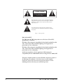
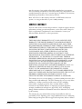
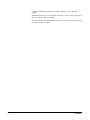
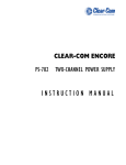
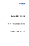
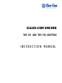
CLEAR-COM ENCORE
TWC-701 AND TWC-704 ADAPTORS
INSTRUCTION MANUAL
TWC-701 and TWC-704 Adaptors Instruction Manual
© 2007 Vitec Group Communications Ltd. All rights reserved.
Part Number 810055Z Rev. 1
Vitec Group Communications, LLC.
850 Marina Village Parkway
Alameda, CA 94501
U.S.A
Vitec Group Communications
7400 Beach Drive
Cambridge Research Park
Cambridgeshire
United Kingdom
CB25 9TP
Vitec Group Communications
Room 1806, Hua Bin Building
No. 8 Yong An Dong Li
Jian Guo Men Wai Ave
Chao Yang District
Beijing, P.R. China 100022
® Clear-Com, CellCom/FreeSpeak and the Clear-Com Communication System logo are registered trademarks of The Vitec Group
plc.
CONTENTS
OPERATION . . . . . . . . . . . . . . . . . . . . . . . . . . . . . . . . . . . . . . . 1-1
Introduction . . . . . . . . . . . . . . . . . . . . . . . . . . . . . . . . . . . . . . . . . . . . . . . . . 1-1
Standard Clear-Com System Wiring . . . . . . . . . . . . . . . . . . . . . . . . . . . . . . . 1-1
TWC-701 and TWC-704 System . . . . . . . . . . . . . . . . . . . . . . . . . . . . . . . . . 1-2
TWC-701 Connectors and Controls . . . . . . . . . . . . . . . . . . . . . . . . . . . . . 1-3
TWC-701 Connection and Operation . . . . . . . . . . . . . . . . . . . . . . . . . . . 1-3
TWC-704 Connectors and Controls . . . . . . . . . . . . . . . . . . . . . . . . . . . . . 1-5
TWC-704 Connection and Operation . . . . . . . . . . . . . . . . . . . . . . . . . . . 1-5
TECHNICAL SPECIFICATIONS . . . . . . . . . . . . . . . . . . . . . . . . . . . . . . 2-1
TWC-701/TWC-704 Adaptors. . . . . . . . . . . . . . . . . . . . . . . . . . . . . . . . . . . 2-1
LIMITED WARRANTY . . . . . . . . . . . . . . . . . . . . . . . . . . . . . . . . . . . 3-I
Warranty Period. . . . . . . . . . . . . . . . . . . . . . . . . . . . . . . . . . . . . . . . . . . . . . . 3-i
Technical Support . . . . . . . . . . . . . . . . . . . . . . . . . . . . . . . . . . . . . . . . . . . . . 3-i
Warranty Repairs and Returns . . . . . . . . . . . . . . . . . . . . . . . . . . . . . . . . . . . . 3-ii
Non-Warranty Repairs and Returns. . . . . . . . . . . . . . . . . . . . . . . . . . . . . . . . 3-ii
Extended Warranty . . . . . . . . . . . . . . . . . . . . . . . . . . . . . . . . . . . . . . . . . . . . 3-ii
Service Contract . . . . . . . . . . . . . . . . . . . . . . . . . . . . . . . . . . . . . . . . . . . . . 3-iii
Liability . . . . . . . . . . . . . . . . . . . . . . . . . . . . . . . . . . . . . . . . . . . . . . . . . . . . 3-iii
TWC-701 AND TWC-704 ADAPTORS
i
ii
TWC-701 AND TWC-704 ADAPTORS
IMPORTANT SAFETY INSTRUCTIONS
1.
2.
3.
4.
5.
6.
7.
Please read and follow these
instructions before operating
this product.
8.
9.
10.
11.
12.
13.
Read these instructions.
Keep these instructions.
Heed all warnings.
Follow all instructions.
Do not use this apparatus near water.
Clean only with dry cloth.
Do not block any ventilation openings. Install in accordance with the
manufacturer’s instructions.
Do not install near any heat sources such as radiators, heat registers, stoves,
or other apparatus (including amplifiers) that produce heat.
Only use attachments/accessories specified by the manufacturer.
Use only with the cart, stand, tripod, bracket, or table specified by the
manufacturer, or sold with the apparatus. When a cart is used, use caution
when moving the cart/apparatus combination to avoid injury from tip-over.
Unplug this apparatus during lightning storms or when unused for long
periods of time.
Refer all servicing to qualified service personnel. Servicing is required when
the apparatus has been damaged in any way, such as power-supply cord or
plug is damaged, liquid has been spilled or objects have fallen into the
apparatus, the apparatus has been exposed to rain or moisture, does not
operate normally, or has been dropped.
WARNING: To reduce the risk of fire or electric shock, do not expose this
product to rain or moisture.
Please familiarize yourself with the safety symbols in Figure 1. When you see
these symbols on this product, they warn you of the potential danger of electric
shock if the station is used improperly. They also refer you to important
operating and maintenance instructions in the manual.
TWC-701 AND TWC-704 ADAPTORS
iii
CAUTION
RISK OF ELECTRIC SHOCK
DO NOT OPEN
This symbol alerts you to the presence of uninsulated dangerous
voltage within the product's enclosure that might be of sufficient
magnitude to constitute a risk of electric shock. Do not open
the product's case.
This symbol informs you that important operating and maintenance instructions are included in the literature accompanying
this product.
Figure 1: Safety Symbols
EMC AND SAFETY
The TWC-701 and TWC-704 products meet all relevant CE and FCC
specifications set out below:
EN55103-1 Electromagnetic compatibility. Product family standard for audio,
video, audio-visual, and entertainment lighting control apparatus for
professional use. Part 1: Emissions.
EN55103-2 Electromagnetic compatibility. Product family standard for audio,
video, audio-visual, and entertainment lighting control apparatus for
professional use. Part 2: Immunity.
And thereby compliance with the requirement of Electromagnetic
Compatibility Directive 2004/108/EC and Low Voltage Directive 2006/95/EC
This device complies with Part 15 of the FCC Rules. Operation is subject to
the following two conditions: (1) this device may not cause harmful
interference, and (2) this device must accept any interference received,
including interference that may cause undesired operation.
iv
TWC-701 AND TWC-704 ADAPTORS
1
OPERATION
INTRODUCTION
Congratulations on choosing this Clear-Com product. Clear-Com was
established in 1968 and remains the market leader in providing intercoms for
entertainment, broadcast and industrial applications. The ruggedness and high
build-quality of Clear-Com products defines the industry standard. In fact, many
of our original beltpacks and main stations are still in daily use around the world.
We recommend that you read through this manual completely to better
understand the functions of the TW-701 and TW-704 adaptors. If you
encounter a situation or have a question that this manual does not address,
contact your dealer or call Clear-Com directly at the factory. Our applications
support and service people are standing by to assist you. (Refer to Chapter 3:
“Warranty” for contact information.) Thank you for selecting Clear-Com for
your communications needs.
STANDARD CLEAR-COM SYSTEM WIRING
Clear-Com stations normally interconnect with “standard” 3-pin XLR
microphone cable (two conductor shielded audio cable). This single cable
provides a single channel of full duplex, two way intercom, “call” signaling, and
the required DC operating power.
Multiple channel systems normally use separately shielded cables for individual
channels. This “single” cable or “pair per channel” system enables ease and
flexibility of station/channel assignments, simple power supply redundancy, and
a minimization of crosstalk between channels.
On standard cabling, one conductor (pin #2) carries power to the remote
stations. The second conductor (pin#3) carries full duplex, two-way intercom
audio and “call” signaling. The shield or drain wire (pin#1) is a common ground
for the power and the intercom audio/signaling.
The intercom line (pin#3) has a 200Ω impedance established by a passive
termination network (one network per channel). This termination is usually
located at the system main station or power supply.
All Clear-Com stations bridge the intercom line with a load impedance of 15Ω
or greater. This results in the audio level remaining constant, without
fluctuations as stations join or leave the channel.
Normally Clear-Com portable two channel intercom stations (usually beltpacks)
are connected with special 2- or 3-pair cables terminated with 6-pin XLR type
connectors. However, in some applications, it is desirable to access two discrete
channels over a single standard 3-pin microphone cable. The TWC-701 and
TWC-704 adaptors combined with intercom stations equipped with the “TW”
option makes two channel operation on a single 3-pin cable possible.
TWC-701 AND TWC-704 ADAPTORS
1-1
TWC-701 AND TWC-704 SYSTEM
The TWC-701 is a stand-alone adaptor that combines two standard Clear-Com
intercom channels (on two separate cables) onto a single standard 3-pin
microphone cable. It does this by combining one channel of intercom audio with
the 30 volts DC operating power.
The TWC-704 adaptor is four channels of the TWC-701 in a single 19-inch
rack mount chassis.
Clear-Com intercom products with TW functionality accept two individual
channels of intercom from one single 3-pin cable. TW functionality in those
products separates the intecom audio from the DC operating power.
If a TW-equipped station is connected to a standard Clear-Com intercom line
(without a TW circuit), only the Channel B portion of the station will operate
normally. Channel A will appear to be inactive. Channel B intercom audio and
“call” signaling is simply passed through the TWC-701 to the intercom station,
and operates in the normal Clear-Com manner.
Because the Clear-Com “call” signal function is normally accomplished by
applying a DC voltage to the intercom audio line, call signaling is deleted from
the Channel A line. When using TW-compatible devices, both channels will
receive and transmit a call signal.
See the RS-601 and RS-603/623/R beltpack manuals for additional TW product
support.
Note:
“TW” is the designation Clear-Com uses for the system of combining the
30 volts DC operating power with the intercom audio. “TW” is derived
from the “two-wire” because by combining the intercom audio with the
DC operating power, a single channel of intercom–with the required
operating power–can be run on only two conductors. However, because
the intercom line is unbalanced audio, Clear-Com does not promote the
use of single-channel operation on two unshielded conductors (i.e.
“twisted pair”). If you have a specific application that requires actual
two-wire operation, please contact the factory (510-337-6600) for
further information.
(A3F)
TWC-701
Channel A
Channel B
TWC-704
RS-603 RS-623R
(mono) (stereo)
(A3F) Line Splitter
To additional
“TW” remote
stations
(A3F)
Figure 1-1: A typical system
1-2
TWC-701 AND TWC-704 ADAPTORS
TWC-701 CONNECTORS AND CONTROLS
The TWC-701 has no operating controls.
Figure 1-2: TWC-701 Rear Connectors
The TWC-701 panel contains:
1. 3-pin male XLR type output connector, labeled “TW.”
2. 3-pin female XLR type input connectors, labeled “CH B” .
3. 3-pin female XLR type input connectors, labeled “CH A”.
4. One circuit breaker reset button.
5. One red LED “short” indicator.
TWC-701 CONNECTION AND OPERATION
1. Connect the desired two channels of standard Clear-Com intercom lines to
the female Channel A and Channel B input connectors.
2. Connect the “TW” remote intercom stations to the male TW two-channel
output connector. More than one station can be connected by either using the
“loop-through” connectors on the individual stations, or by using passive
3-pin XLR type “splitters.”
3. The TWC-701 can supply up to 1.6 amperes of DC power before it will trip.
After the short or overload condition is removed reset the circuit breaker using
the reset button on the unit.
4. The TWC-701 internal current limit protects against short circuits. A
short-circuit or overload on the TW line will cause the red short LED to come
on. To reset the unit press the red reset button on the unit.
TWC-701 AND TWC-704 ADAPTORS
1-3
Note:
1-4
Only Clear-Com intercom stations equipped with a TW option should
be connected to the output of the TWC-701. If a station not equipped
with the “TW” option is connected to the TW intercom line, the studio
portion of channel A will be loaded down, reducing volume level and
changing sidetone characteristics on that channel. (However, if a
non-TW equipped station is accidentally connected to the TW line, no
damage will be caused to the TWC-701/TWC-704 or any system
component.)
TWC-701 AND TWC-704 ADAPTORS
TWC-704 CONNECTORS AND CONTROLS
The TWC-704 has no operating controls.
The TWC-704 panel contains:
Figure 1-3: TWC-704 Rear Connectors
1. Four 3-pin female XLR type input connectors labeled “CH B”.
2. Four 3-pin female XLR type input connectors labeled “CH A”.
3. Four 3-pin male XLR type output connectors, labeled “TW.”
4. Four green LED “power good” indicators, labeled “PWR.”
TWC-704 CONNECTION AND OPERATION
1. Connect the desired two channels of standard Clear-Com intercom lines to a
pair of female Channel A and Channel B input connectors.
2. Connect the “TW” remote intercom stations to the corresponding male TW
output connector. More than one station can be connected by either using the
“loop-through” connectors on the individual stations, or by using passive
3-pin XLR type “splitters.”
3. The TWC-704 can supply up to 1.1 ampere of DC power before it will trip.
After the short or overload condition is removed, the unit will automatically
restore to normal operation.
4. The TWC-704 internal current limit protects against short circuits. A
short-circuit or overload on the TW line will cause the green “PWR” LED to
go out. The internal protection will automatically recover when the short or
overload condition is removed.
Note:
TWC-701 AND TWC-704 ADAPTORS
Only Clear-Com intercom stations equipped with a TW option should
be connected to the output of the TWC-704. If a station not equipped
with the “TW” option is connected to the TW intercom line, the studio
portion of channel A will be loaded down, reducing volume level and
changing sidetone characteristics on that channel. (However, if a
non-TW equipped station is accidentally connected to the TW line, no
damage will be caused to the TWC-701/TWC-704 or any system
component.)
1-5
1-6
TWC-701 AND TWC-704 ADAPTORS
2
TECHNICAL SPECIFICATIONS
TWC-701/TWC-704 ADAPTORS
Rear Panel Connectors (TWC-701)
Intercom in
TW
Rear Panel Connectors (TWC-704)
Intercom in
TW
Rear Panel Controls & Indicators (TWC-701)
Rear Panel Controls & Indicators (TWC-704)
Power Requirements (TWC-701)
Input Voltage:
Input Current: (idle)
Current Trip
Power Requirements (TWC-704)
Input Voltage:
Input Current: (idle)
Current Trip
Environmental
Dimensions (TWC-701)
Dimensions (TWC-704)
Weight
TWC-701
TWC-704
TWC-701 AND TWC-704 ADAPTORS
(2) XLR3F
(1) XLR3M
(8) XLR3F (2 per channel)
(4) XLR3M (1 per channel)
(1) Reset switch
(1) Overload LED
(4) Power LED
20-30 VDC
<= 30mA
1.6A
20-30 VDC
<= 120mA
1.1A
32o to 122o F (0o to 50o C)
H 2.0" W 4" D 5.0"
(51 x 101 x 127 mm)
19 in. W x 1.75 in. H x 7.0in. D
(483 mm x 44 mm x 1678mm)
1.1 lbs. (0.503 kg)
2.64 lbs (1.2 kg)
2-1
Notice About Specifications
While Clear-Com makes every attempt to maintain the accuracy of the
information contained in its product manuals, that information is subject to
change without notice. Performance specifications included in this manual are
design-center specifications and are included for customer guidance and to
facilitate system installation. Actual operating performance may vary.
2-2
TWC-701 AND TWC-704 ADAPTORS
LIMITED WARRANTY
Vitec Group Communications (VGC) warrants that at the time of purchase, the
equipment supplied complies with any specification in the order confirmation
when used under normal conditions, and is free from defects in workmanship
and materials during the warranty period.
VGC offers 24 x 7 customer
support if you have an
Extended Warranty or
Service Contract.
Return Material
Authorization (RMA)
numbers are required for all
returns.
Both warranty and
non-warranty repairs are
available.
During the warranty period VGC, or any service company authorized by VGC,
will in a commercially reasonable time remedy defects in materials, design, and
workmanship free of charge by repairing, or should VGC in its discretion deem it
necessary, replacing the product in accordance with this limited warranty. In no
event will VGC be responsible for incidental, consequential, or special loss or
damage, however caused.
WARRANTY PERIOD
The product may consist of several parts, each covered by a different warranty
period. The warranty periods are:
• Cables, accessories, components, and consumable items have a limited
warranty of 90 days.
• Headsets, handsets, microphones, and spare parts have a limited warranty of
one year.
• UHF wireless IFB products have a limited warranty of one year.
• UHF wireless intercom systems have a limited warranty of three years.
• All other Clear-Com and Drake brand systems and products, including
beltpacks, have a limited warranty of two years.
The warranty starts at the time of the product’s original purchase. The warranty
start date for contracts which include installation and commissioning will
commence from the earlier of date of the Site Acceptance Test or three months
from purchase.
TECHNICAL SUPPORT
To ensure complete and timely support to its customers, VGC’s User Support
Center is staffed by qualified technical personnel. Telephone and email technical
support is offered worldwide by the User Support Center.
The User Support Center is available to VGC’s customers during the full course
of their warranty period. Telephone support during the warranty period will be
offered at no charge between 09:00 and 17:00 according to the customer’s local
time zone.
In addition, for customers who purchase an Extended Warranty or Service
Contract, 24-hour customer support is offered immediately upon purchase of
WARRANTY
i
such agreement. For more information, contact your authorized dealer,
distributor, or sales representative.
Instructions for reaching VGC’s User Support Centers are given below.
Telephone for Europe, Middle East and Africa: +49 40 6688 4040
Telephone for the Americas and Asia: +1 510 337 6600
Email: [email protected]
Once the standard warranty period has expired, the User Support Center will
continue to provide telephone support if you have purchased an Extended
Warranty or Service Contract. In these cases, you will have access to telephone
support 24 hours per day, 7 days per week.
WARRANTY REPAIRS AND RETURNS
Before returning equipment for repair, contact a User Support Center to obtain a
Return Material Authorization (RMA). VGC representatives will give you
instructions and addresses for returning your equipment. You must ship the
equipment at your expense, and the support center will return the equipment at
VGC’s expense.
For out-of-box failures, use the following contact information:
Europe, Middle East and Africa
Tel: +44 1223 815000 Email: [email protected]
North America, Canada, Mexico, Caribbean & US Military
Tel: +1 510 337 6600 Email: [email protected]
Asia Pacific & South America
Tel: +1 510 337 6600 Email: [email protected]
VGC has the right to inspect the equipment and/or installation or relevant
packaging.
NON-WARRANTY REPAIRS AND RETURNS
For items not under warranty, you must obtain an RMA by contacting the User
Support Center. VGC representatives will give you instructions and addresses for
returning your equipment.
You must pay all charges to have the equipment shipped to the support center
and returned to you, in addition to the costs of the repair.
EXTENDED WARRANTY
If you purchase an Extended Warranty, you are also given access free of charge to
the User Support Center 24 hours a day, 7 days a week.
You can purchase an extended warranty at any time during the first two years of
ownership of the product. The purchase of an extended warranty extends to five
ii
WARRANTY
years the warranty of any product offered with a standard two-year warranty.
The total warranty period will not extend beyond five years. Any purchase of an
extended warranty provides 24 x 7 customer support in addition to the warranty
immediately upon purchase of the warranty extension.
Note: VGC does not offer warranty extensions on UHF wireless intercom
systems, or on any product with a 1-year or 90-day warranty.
SERVICE CONTRACT
VGC also offers service contracts that provide 24 x 7 telephone support, advance
replacements, training, proactive maintenance, on-site visits, and no charge for
repair or replacement of equipment. For more information, contact your
authorized dealer, distributor, or sales representative.
LIABILITY
THE FOREGOING WARRANTY IS VGC'S SOLE AND EXCLUSIVE
WARRANTY. THE IMPLIED WARRANTY OF MERCHANTABILITY
AND FITNESS FOR A PARTICULAR PURPOSE AND ANY OTHER
REQUIRED IMPLIED WARRANTY SHALL EXPIRE AT THE END OF
THE WARRANTY PERIOD. THERE ARE NO OTHER WARRANTIES
(INCLUDING WITHOUT LIMITATION WARRANTIES FOR
CONSUMABLES AND OTHER SUPPLIES) OF ANY NATURE
WHATSOEVER, WHETHER ARISING IN CONTRACT, TORT,
NEGLIGENCE OF ANY DEGREE, STRICT LIABILITY OR OTHERWISE,
WITH RESPECT TO THE PRODUCTS OR ANY PART THEREOF
DELIVERED HEREUNDER, OR FOR ANY DAMAGES AND/OR LOSSES
(INCLUDING LOSS OF USE, REVENUE, AND/OR PROFITS). SOME
STATES DO NOT ALLOW THE EXCLUSION OR LIMITATION OF
INCIDENTAL OR CONSEQUENTIAL DAMAGES OR THE
LIMITATION ON HOW LONG AN IMPLIED WARRANTY LASTS, SO
THE ABOVE LIMITATIONS MAY NOT APPLY TO YOU. IN ANY
EVENT, TO THE MAXIMUM EXTENT PERMITTED UNDER
APPLICABLE LAW, VGC'S LIABILITY TO CUSTOMER HEREUNDER
SHALL NOT UNDER ANY CIRCUMSTANCES EXCEED THE COST OF
REPAIRING OR REPLACING ANY PART(S) FOUND TO BE
DEFECTIVE WITHIN THE WARRANTY PERIOD AS AFORESAID.
This warranty does not cover any damage to a product resulting from cause other
than part defect and malfunction. The VGC warranty does not cover any defect,
malfunction, or failure caused beyond the control of VGC, including
unreasonable or negligent operation, abuse, accident, failure to follow
instructions in the manual, defective or improperly associated equipment,
attempts at modification and repair not approved by VGC, and shipping
damage. Products with their serial numbers removed or defaced are not covered
by this warranty.
This warranty does not include defects arising from installation (when not
performed by VGC), lightning, power outages and fluctuations, air conditioning
failure, improper integration with non-approved components, defects or failures
WARRANTY
iii
of customer furnished components resulting in damage to VGC provided
product.
This limited warranty is not transferable and cannot be enforced by anyone other
than the original consumer purchaser.
This warranty gives you specific legal rights and you may have other rights which
vary from country to country.
iv
WARRANTY