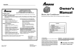
1
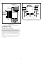
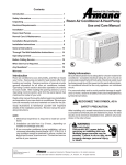
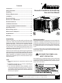
Contents
Introduction .................................................................. 1
Safety Information ....................................................... 1
Room Air Conditioner & Heat Pump
Unpacking .................................................................... 2
Use and Care Manual
Electrical Requirements .............................................. 2
Installation ................................................................... 3
Room Heat Pumps ....................................................... 3
Normal Care & Maintenance ...................................... 3
General Instructions .................................................... 5
Installation Instructions ............................................... 6
Through-The-Wall Installation Instructions ............. 12
Operating Controls .................................................... 15
Before Calling Service .............................................. 17
When Service Is Required ........................................ 18
Any Questions? .......................................................... 18
Warranty ..................................................................... 20
Introduction
Room air conditioners cool, dehumidify, and filter air inside
your home. Heat pump and electric heat models offer both
heating and cooling. Opening sections of manual provide
general information for all room air conditioner models.
Operating Controls section describes operation of controls
for each model. After reading the opening sections, turn to
Operating Controls section and find the panel layout that
matches the model of your unit.
Read entire manual thoroughly before beginning installation
and operation of your new room air conditioner. Be sure you
have all necessary tools and materials on hand for the job.
Study illustrations to familiarize yourself with important
details of the installation process. Review manual for operating instructions.
NOTE
1. Mechanical experience is required to install air conditioner.
2. Installation can take from 1 to 3 hours, depending on
installer’s knowledge and skill.
3. If you encounter problems during installation, call our
consumer information line toll-free at 1-877-376-0214. If
your problem cannot be resolved by phone, contact an
authorized Amana® brand servicer. Contact and service
will be at your expense.
IO-372A
©2010 Goodman Company, L.P.
Effective: May 2010
Safety Information
Be sure electrical service is adequate for chosen model of air
conditioner. Complete electrical rating for unit is found on
serial plate located behind front grille. Electrical outlet must
be close enough to unit for power cord to reach without strain.
Air conditioner should be the only appliance on individual
circuit.
For personal safety and to avoid possible damage to appliance or home, observe all safety instructions highlighted by
symbol shown below.
RECOGNIZE THIS SYMBOL AS A
SAFETY PRECAUTION.
After installing unit, reread instructions to ensure each step
is complete and that all parts are fastened in place. For best
results and to minimize installation time, perform all procedures in the order shown.
WARNING
is a registered trademark of Maytag Corporation or its related companies
and is used under license to Goodman Company, L.P., Houston, TX. All rights reserved.
OWNER'S PRODUCT IDENTIFICATION
WARNING
MODEL NUMBER
SERIAL NUMBER
MANUFACTURING NUMBER
Owner's Name
Address
WARNING
City
State
/
Zip
/
Date of Purchase
Authorized Dealer
Address
WARNING
City
(
HIGH TEMPERATURE STRESS HAZARD
This room air conditioner is not meant to provide
unattended cooling or life support for persons or
animals that are unable to react to failure of the
product.
State
Zip
)
Phone Number
WARNING
The failure of an unattended air conditioner may
result in extreme heat in the conditioned space
causing overheating or death or persons or
animals.
To avoid death, personal injury or property
damage due to electrical shock:
•
•
•
•
Precautions must be taken to ward off or guard
against such an occurrence.
•
•
Unpacking
Unpack and visually inspect the unit. Report any damage to
the delivering carrier immediately. Remove and discard all
packing material.
•
WARNING
Do NOT operate unit with shipping foam
blocks in place. Always remove prior to
running unit.
•
On some models the air conditioner front and/or mounting kit
hardware may be packed separately.
•
•
•
•
Record the model, serial and manufacturing numbers of your
unit in the space provided below. This information is found on
a nameplate visible after the front of the air conditioner has
been removed. The rated voltage, amperage and capacity for
your specific model can also be found on this nameplate.
Read the warranty packaged with the unit. Keep the warranty
and a copy of your sales receipt for future reference. You may
also want to record in the space provided the date purchased
and the selling dealer.
Observe all local codes and ordinances.
Disconnect electrical power to unit before servicing.
Ground appliance properly.
Check with a qualified electrician if you are not
sure this appliance is properly grounded.
DO NOT ground to gas line.
DO NOT ground to cold water pipe if pipe is
interrupted by plastic, non-metallic gaskets, or
other insulating (non-conducting) materials.
DO NOT modify plug on power cord. If plug
does not fit electrical outlet, have proper outlet
installed by qualified electrician.
DO NOT have a fuse in the neutral or ground
circuit. A fuse in the neutral or ground circuit
could result in an electrical shock.
DO NOT use an extension cord with this appliance.
DO NOT use an adapter plug with this appliance.
DO NOT pinch power cord.
DO NOT REMOVE warning tag from power cord.
Electrical Requirements
Grounding Instructions
This appliance is equipped with a three-prong grounding plug
for protection against possible shock hazards. If a two-prong
2
Unit Plug
Type
Receptacle
Required
•
Circuit Rating, Voltage
Breaker, Time Rating On
Delay Fuse
Nameplate
NEMA No. 5-15P NEMA No. 5-15R 125V-15AMP
115V
•
NEMA No. 6-15P NEMA No. 6-15R 250V-15AMP
230/208V rated
at 12 amperes or
less
NEMA No. 6-20P NEMA No. 6-20R 250V-20AMP
230/208V rated
over 12 amperes,
but not more than
16 amperes
NEMA No. 6-30P NEMA No. 6-30R 250V-30AMP
208V rated over
16 amperes, but
not more than
24 amperes
Room Heat Pumps
Heat pumps work by moving heat instead of creating it. In the
summer, the cool indoor coil absorbs heat from your room
and moves it outdoors, providing cooling. In the winter, heat
pumps reverse this operation. By lowering the temperature
of the outdoor coil below the outdoor temperature, the heat
pump absorbs the heat from outdoors and moves it inside
your house. This heat transferring process is very efficient.
For example, at 45°F outdoor temperature, a heat pump can
provide 2 ½ watts of heat for every watt of electricity it
consumes.
wall receptacle is encountered, the customer is required to
contact a qualified electrician and have the two-prong wall
receptacle replaced with a properly grounded three-prong
wall receptacle in accordance with the National Electrical
Code.
As outdoor temperatures drop, the heating capacity and
efficiency of the heat pump declines. At temperatures below
45°F, it is likely that ice will form on the outdoor coil. Heat
pump units are designed to operate as a heat pump above
approximately 40°F. Below 40°F, these units switch automatically from reverse cycle heat pump to auxiliary electric
heating. No defrost is required. There is no minimum
operating temperature.
Room air conditioners are designed to operate according to
requirements on the nameplate and as shown in Table 1.
Fuse or circuit breaker ratings must be according to the fuse
instruction label and as shown in Table 1. Do not plug models
marked “Use on Single Outlet Circuit Only” into a circuit with
another appliance or light fixture.
Receptacle Wiring
Receptacle wiring must be of adequate size for unit. Refer
to unit identification plate for exact power requirements.
Minimum size of wiring, based on power requirements, is:
Units up to 20 amps:
20–30 amp units:
Unit with a window mounting kit
These models are designed for mounting though an
opening in a wall. These units can be adapted to
window installation by using the optional window mounting kit supplied with your unit.
Unit without a window mounting kit
No window mounting kit is supplied with the unit.
These models are designed for mounting through an
opening in a wall. These units can be adapted to
window installation by purchasing an optional window
mounting kit. Consult your dealer to choose the kit that
is appropriate for your model and installation.
Normal Care and Maintenance
WARNING
12 gauge
10 gauge
Use copper wire only. Consumer’s responsibility is to provide
proper and adequate receptacle wiring that conforms to all
applicable codes. All wiring should be installed by qualified
electrician.
LCDI or AFCI Power Cords
Underwriters Laboratories (UL) and the National Electric
Code (NEC) now require power cords that sense current
leakage and can open the electrical circuit to the unit. In the
event, the unit does not operate, check the reset button
located on or near the head of the power cord as part of the
normal troubleshooting procedure.
CAUTION
Installing an air conditioner through a wall requires
extensive carpentry and/or masonry experience.
Thru-wall installations performed by inexperienced
or unqualified individuals can result in costly
damage to home or result in equipment malfunction
that could cause property damage, personal injury
or death.
Installation
Complete step-by-step installation instructions are furnished
with your unit. These instructions will be found on a separate
page included with this manual or in the mounting kit
assembly. Follow these instructions carefully. Keep these
instructions with this manual for future reference. Your unit
will be one of the following designs:
3
Annual Inspection
It is suggested that your unit be inspected by your dealer or
servicer once a year. It is advisable to have the outer case
removed and the unit thoroughly cleaned.
Optional Charcoal Air Filter Installation
Remove charcoal air filter from plastic bag. Insert three tabs
on right side of filter into three slots on filter frame. Carefully
bow middle of filter until two tabs on filter can be inserted into
two slots on filter frame. Relax bow.
Note: The life of your unit may be greatly reduced if you live
in a salt air or other corrosive type environment. Under these
conditions, the unit should be removed from its case and
completely cleaned at least once a year. At that time any
scratches or blisters on the painted surfaces should be
sanded and repainted. Placing an algaecide tablet in the
outdoor side of the unit’s basepan is suggested in humid
areas where algae formation is common. We recommend the
following algaecide cleaners: PanGuard® by Control Released
Technologies, Inc. and CDC Anti-Clog® by Virginia KMP.
Reinstall air filter by reversing removal procedure.
Front Grille and Filter Removal
The front contains an air filter that can be removed. To clean
the filter, use the following method for filter removal.
Front Grille and Cabinet Cleaning
Grille and cabinet may be cleaned with warm water and mild
soap or detergent. Cleaning and polishing compounds are not
recommended, as they may damage plastic surfaces.
Grasp exhaust grille and hinge up.
Air Filter Cleaning
A dirty air filter reduces operating efficiency of unit. Filter
should be inspected at least once every week during operation. Clean filter with vacuum cleaner or wash in warm water
and mild detergent. Filter should be thoroughly dried before
replacing in unit. Do not operate unit without filter in place.
Fan Motor Care
The fan motor is permanently lubricated for long life. There is
no need to oil the motor.
Slide-out Chassis Removal from Outer Case
Grasp filter handle and slide filter out of unit.
1. Hinge front grille up.
2. Remove air filter by grasping handle and lifting up.
3. Remove 3 screws (1 each side and 1 behind filter) holding
plastic front to unit and remove front.
4. If the unit has a screw holding the basepan clip to the
chassis, remove the screw.
CAUTION
To reduce the risk of personal injury, be sure to
have sufficient help when moving your unit. A
room air conditioner can weigh between 70 and
240 pounds.
5. Using basepan handle, pull chassis straight out, slowly
and evenly, until approximately 9-12 inches extends from
outer case. Use both hands to grasp basepan and pull
remaining chassis from outer case.
NOTE: Basepan clip is shipped in plastic bag with mounting
screw and condensate drain cup. Install clip after reinserting
chassis into outer case to prevent accidental chassis removal.
4
Drain Cup Installation and Use
Your air conditioner uses a system where the water removed
from the indoor air (condensate) is channeled to the outdoor
side of the unit. The outdoor fan blade has a “slinger” ring
attached to it that dips into the water and slings the water onto
the outdoor coil surface. This is the sound of water you hear
during normal operation. The water quickly evaporates on this
warm surface and improves the efficiency of your air conditioner.
In normal conditions the unit can evaporate the water as fast
as it is removed from the indoor air.
Chassis
However, in very humid conditions excess amounts of water
may drip off the unit chassis. If this proves to be a problem,
install the condensate drain cup included with the unit to route
excess water where it would not be a problem (see illustration
below).
To install, remove the unit chassis from the outer case. Insert
the condensate drain cup through the recessed ½” hole on the
back center flange of the outer case. Once inserted, place a
½” diameter hose or tube on the drain cup bottom spout. The
hose allows you to route where you want the excess water to
go. Reinsert the unit chassis into the outer case. The unit
basepan overflow hole will be positioned directly above the
drain cup and will catch any water that might run out.
Plastic Front
General Operating Instructions
While operation of all units is similar, controls vary slightly
from model to model. Operating Controls section shows
control panel of unit purchased and gives detailed information
about operation of controls.
Initial Start-Up and Cooling
Select the highest fan speed and set temperature control to
its coldest position. When the desired temperature is
reached, slowly move the temperature control toward a
warmer setting until the compressor shuts off. The thermostat will then cycle the compressor on and off to maintain this
selected temperature. Adjust the fan speed for desired air
circulation.
Outer Case
Baffles
Condensate
Drain Cup
1/2" Diameter
Hose
Indoor
Grille
Switchover Thermostat Control
Emergency heat switch overrides heat pump (compressor)
and starts auxiliary electrical heater. When switch is ON,
heat pump is locked out.
Outdoor
Louvers
•
Changing Airflow Direction Baffles
Airflow on unit may be diverted left or right from center by
baffles. Upward and downward air discharge is provided by
tilting louvers. Adjust baffles and tilt louvers for desired
airflow pattern. Unit also has automatic left to right air
movement with "Circulaire" feature. (See page 15 under
Operating Controls.)
Airflow Around Unit
Check the indoor grille and outdoor louvers for obstructions to
airflow. Do not block the airflow to and from the unit. If air is
obstructed and/or deflected back into the unit, the air
conditioner’s compressor may cycle on and off rapidly. This
could damage your unit.
5
Use emergency switch only when heat pump fails to
provide adequate heat. Cause of heat pump malfunction should be determined by authorized servicer. Cost
of operating unit will increase when emergency heat
switch is engaged.
Installation
Instructions
WARNING
Air Conditioner
Disconnect ALL power to unit before installing or servicing, making
sure unit is plugged in only when instructions state it is safe to do so.
Failure to follow instructions may cause property damage, personal
injury or death.
Question? Consumer information line toll-free 1-877-376-0214
CAUTION
BEFORE YOU BEGIN
Do not, under any circumstances, cut or
remove the third (ground) prong from the
power cord.
Read these instructions completely and carefully.
Do not change the plug on the power cord of
this air conditioner.
• IMPORTANT - Save these instructions for local
inspector's use.
Aluminum house wiring may present special
problems - consult a qualified electrician.
• IMPORTANT - Observe all governing codes and
ordinances.
• Note to Installer - Be sure to leave these instructions
with the Consumer.
TOOLS YOU WILL NEED
• Not to Consumer - Keep these instructions for future
reference.
• Skill level - Installation of this appliance requires basic
mechanical skills.
Adjustable
Adjustable
wrench wrench
• Completion time - Approximately 1 hour
• We recommend that two people install this product.
• Proper installation is the responsibility of the installer.
• Product failure due to improper installation is not
covered under the Warranty.
Phillips head
head screwdriver
screwdriver
Phillips
Pencil
ELECTRICAL REQUIREMENTS
The 3-prong grounding plug minimizes the
possibility of electric shock hazard. If the wall
outlet you plan to use is only a 2-prong outlet, it is
your responsibility to have it replaced with a
properly grounded 3-prong wall outlet.
Level
Some models require 230/208-volt a.c.
protected with a time delay fuse or circuit
breaker. These models should be installed on
their own single branch circuit for best
performance and to prevent overloading
house or apartment wiring circuits, which
could cause a possible fire hazard from
overheating wires.
Flat-blade screwdriver
Ruler or tape measure
Scissors or knife
Power cord includes a current interrupter device.
A test and reset button is provided on the plug
case. The device should be tested on a periodic
basis by first pressing the TEST button and then
the RESET button. If the TEST button does not trip
or if the RESET button will not stay engaged,
discontinue use of the air conditioner and contact a
qualified service technician.
6
InstallationInstructions
Instructions
Installation
PARTS INCLUDED
Window
sash seal
(A ppearance m ay vary)
Left
accordion
panel
Top
mounting
rail
Foam top
window gasket
Right
accordion
panel
V-support (2)
Window locking
bracket (2)
Type A (6)
Bolt (2) & nuts (2)
Type B (4)
Type D (6)
Type C (7)
7
Type E ((4)
Type F (2)
Installation
Instructions
Installation
Instructions
3 REMOVE THE AIR CONDITIONER
FROM THE CASE
1 WINDOW REQUIREMENTS
• These instructions are for a standard doublehung window. You will need to modify them for
other types of windows.
• The air conditioner can be installed without the
accordion panels if needed to fit in a narrow
window. See the window opening dimensions.
• All supporting parts must be secured to firm
wood, masonry or metal.
• The electrical outlet must be within reach of the
power cord.
A
B
Remove the locking screw and locking
bracket from the lower frame. Save to
reinstall later.
Remove the ground screw and save to
reinstall later.
Remove shipping screws
(if present) and discard
Remove the ground screw and save to reinstall later.
C
Slide the air conditioner from the case by
gripping the base pan handle and pulling
forward while bracing the case.
2 STORM WINDOW REQUIREMENTS
• A storm window frame will not allow the air
conditioner to tilt toward the outside, and will
keep it from draining properly.
To adjust for this, attach a piece of wood to
the stool.
WOOD PIECES
WIDTH: 2"
LENGTH: Long enough to fit inside the window
frame.
THICKNESS : To determine the thickness, place a
piece of wood on the stool to make it 1/2" higher
than the top of the storm window frame.
Attach securely with nails or screws
provided by the installer.
4 PREPARE THE WINDOW
Cut the window sash seal to the proper
length. Peel off the backing and attach the
seal to the underside of the window sash.
Wood
1/2" higher
than frame
Stool
Storm
window
frame
8
Installation
Instructions
Installation Instructions
6 INSTALL THE CASE
5 PREPARE THE CASE
IN THE WINDOW
A Install the top mounting rail with 4 type B
Carefully
case
intointo
thethe
window
andand
Carefullyslide
slidethe
the
case
window
A center
thethe
window
behind
centerthe
thecase.
case.Lower
Lower
window
behind
the
thethe
bottom
of the
the top
top mounting
mountingrail.
rail.Pull
Pull
bottom
of the
caseforward
forwardsosothat
that
bottom
mounting
case
thethe
bottom
mounting
railisistight
tightagainst
againstthe
the
back
window
rail
back
of of
thethe
window
stool. Mount
Mount the
the case
casetoto the
the window
windowsill
sillusing
using
stool.
4
type
E
screws.
Drill
pilot
holes,
if
necessary
.
4 type E screws. Drill pilot holes, if necessary.
screws from the inside of the case.
B Insert the frames for the accordion panels
into the top mounting rail and the bottom
frame guides. Attach the accordion panels
to the side of the case using 3 type A screws
on each side.
Note: When attaching the accordion panels,
make sure to only screw the inner panels
to the case sides.
Top mounting rail
4 type E screws
Stool
S tool
Make
allall
of of
thethe
Make sure
surethe
thebolts
boltsand
andnuts
nutsare
are
B way
wayininboth
boththe
theleft
leftand
andright
rightV-supports.
-supports.
V
Bottom frame guides
Bolt and nut
Position
on the
the case
case bottom
bottom
Position the
the V-supports
V-supports on
C so
that they will be near the outside wall.
so that they will be near the outside wall.
Attach
Attach aa V-support
V-support to
to each
each side
sideofofthe
the
bottom
bottom of
of the
the case
case using
usingtype
typeCCscrews,
screws,
3 on
on each
each side.
side.
3
V-support
9
Installation
Instructions
Ins tallation Ins
tructions
6 INSTALL
THE CASE
IN THE WINDOW (cont.)
7 INSTALL
Adjustthe
theleveling
levelingbolts
bolts
and
nuts
against
and
nuts
against
the the
D Adjust
outsidewall
wallsosothat
that
case
a slight
outside
thethe
case
hashas
a slight
tilt tilt
to
the
outside.
i
T
ghten
nuts
with
an
adjustable
to the outside. Tighten nuts with an adjustable
wrench. Use a level; about a 1/2 bubble will
wrench. Use a level; about a 1/2 bubble will
be the correct case slant to the outside.
be the correct case slant to the outside.
SUPPORT BRACKETS
AND THE FOAM TOP WINDOW
GA S K E T
ttach the s upport brackets with two
A A
type D s crews , one on each s ide.
the foam top window gas ket to the
B Cut
window width.
the foam between the glas s and the
C Stuff
window to prevent air and ins ects from
getting into the room .
E Use a wood block (obtained locally) between
the leveling bolts and the wall if the wall is
weak or if the weight of the air conditioner
falls between the studs in the wall.
F Extend the left and right accordion panels
to the vertical window sashes. Drill pilot
holes and attach the top and bottom corners
with 4 type D screws.
Top mounting rail
Type D
screw
Type D
screw
Type D
screw
Type D
screw
10
Installation
Instructions
Ins tallatio n I nstructio
ns
8 INS TALL THE AIR CONDITIONER
8 INSTALL THE AIR CONDITIONER
IN THE CASE
IN THE CASE(cont.)
Slide the
the air
air
A Slide
conditioner into
conditioner
into
the case.
case. Do
the
Donot
not
push
on the
the
push on
controls
orthe
the
controls or
finned
finned coils.
coils.
Make
surethe
the
Make sure
air
air conditioner
conditioner
is
seated.
is firmly
firmly seated.
Pull the
the coiled
coiled power
power cord
cord from
from its
its shipped
shipped
G Pull
positionininthe
theairairdischarge
discharge
area.
Attach
position
area.
Attach
the
the front grille frame to the case by inserting
front grille frame to the case by inserting the tabs
the tabs on the grille frame into the slots
on
into
thecase.
slots on
the front
top
onthe
thegrille
frontframe
top of
the
Push
the grille
of
the case.
Push
the grille
in. Install
the
frame
in. And
install
the 2 frame
side screws
at bottom
2left
Type
F screws
at the
left and right sides
and
right side
ofbottom
front panel.
of the front panel.
B Reinstall the locking bracket and screw
removed earlier
.
Guide the lever carefully
through the grille fram e
as you pus h it in.
C Reconnect the ground wire to the air
conditioner using the screw removed earlier
.
IMPOR TANT : The ground wire must be
reinstalled to ensure a proper ground.
H Secure the front grille frame to the case
with one type C screw
.
Remove the
thefront
frontgrille
grille
from
its box
from
its box
and and
D Remove
removethe
theshipping
sh
ipping tape.
tape.
remove
I Reinstall the filter.
the inlet grille at the bottom corners
E Grasp
and pull it forward. Unhook it from its top
hinges and set it aside.
.
J Reinstall the inlet grille. Connect power
the tab, pull up slightly on the filter
F Using
to release it and pull it down and out.
11
Thru-wall Installation Instructions
for Amana® Brand Room Air Conditioner
Introduction
This instruction sheet provides guidelines for installing a
compact air conditioner through an outside wall.
26”
WARNING
16 7/8”
9”
AE18: 25 3/5”
AH18: 28 1/3”
CAUTION
Installing an air conditioner through a wall requires
extensive carpentry and/or masonry experience.
Thru-wall installations performed by inexperienced
or unqualified individuals can result in costly
damage to home or result in equipment malfunction
that could cause property damage, personal injury
or death.
Front of
outer case
Bottom rail
/2 "
Air Conditioner Dimensions
The following figures show the outside dimensions of air
conditioner with chassis installed, and dimensions of outer
case with chassis removed.
3”
Dimension of Bottom Rail
Outer Case Dimensions
(chassis removed)
General Instructions
All Amana® brand Compact Room Air Conditioners feature
a slide-out chassis. Chassis and front cover must be removed from outer case for installation.
Air Conditioner Dimensions
is a registered trademark of Maytag Corporation or its related
companies and is used under license to
Goodman Company, L.P., Houston, TX. All rights reserved.
(with chassis installed)
12
Brick Veneer or Frame Wall Construction
CAUTION
See CAUTION under General Instructions. Cut or build
rough opening large enough to allow a framed, finished
opening 17-inches high and 26 1/8-inches wide. When case
is properly positioned in opening, secure it to framing material with nails or screws driven through holes in sides of
outer case (shim case and predrill holes before securing).
In order to reinstall the chassis and reattach the air conditioner front cover, the
installed outercase must be square and
level from side to side. Use wood shims
between sides of case and finished opening - especially where case is secured to
opening - to prevent warping or distorting.
Check installed case for distortion using
carpenter's square.
A finished opening 26 1/8-inches wide x 17-inches high is
recommended. The lower left inside corner of opening must
be within 5 feet of an appropriate electrical outlet (see Use
and Care manual for electrical requirements.)
17”
Framing
lumber
When wall thickness exceeds 9-inches, opening must be
modified to allow air to enter side louvers on case (see special instructions on back ). Do not install air conditioner in
walls thicker than 11 2/5-inches.
26 1/8”
Framed/Finished Opening
(brick veneer or frame wall construction)
Placement of Outer Case in Opening
Place outer case in opening, flush against one side of
opening. Use carpenter’s level and ensure case is level
from side to side and has a 3/8-inch slope from front to back
(back of case must be 3/8-inch lower than front to ensure
proper condensate drainage). If needed, use shims to level
case (from side to side) and to obtain proper back slope.
Front of case must project ¾-inch (minimum) beyond inside wall in order to attach air conditioner front frame. If
framing indoor side of opening with wood molding (or other
decorative material), extend outer case ¾-inch beyond
molding.
Dimensions of Finished Opening
Masonry Construction
When case is properly positioned in opening, use wood
shims to fill any gaps between case and finished opening,
especially in area where case will be secured to opening.
Take care not to warp or distort case when installing
shims. For condensate drainage, install drainage cup in
drain hole on baseplate of case.
See CAUTION under General Instructions. In masonry
walls, cut or build a finished opening 17-inches high by
26 1/8-inches wide. When case is properly positioned in
opening, secure it in place with mortar or concrete nails
driven through holes in sides of outer case (shim case and
predrill holes before securing with nails).
13
Outercase must project
a minimum ¾"
beyond inside wall
or molding to attach front frame
Lintel and
flashing
(if required)
5
93/8"
Front of outer case
to side air louvers
with 3/8"
drainage
Caulk all
sides
Chamfering Walls Thicker Than 9-inches
Optional
molding
(not provided)
Installed Case
(brick veneer or frame wall construction shown)
Installation in Wall
Thicker Than 9-inches
The side louvers in outer case provide ventilation to air conditioner compressor and fan motor and must not be
blocked. When installing unit in a wall over 9-inches thick,
provisions must be made in wall opening to ensure free air
flow to the side louvers. This can be accomplished by
chamfering the vertical portions of the outside opening as
shown.
Ventilation louvers on top of case must not be obstructed.
Do not attempt to install unit in walls thicker than
11 2/5-inches.
14
Operating Controls
Controls
Operating your air conditioner properly helps you to obtain the
best possible results.
n
Power Pad (Button)
Turns air conditioner on and off. When turned on, the
display will show the room temperature.
This section explains proper air conditioner operation.
IMPORTANT:
•
If you turn off the air conditioner, wait at least 3 minutes
before turning it back on. This prevents the air conditioner from blowing a fuse or tripping a circuit breaker.
Do not try to operate your air conditioner in the cooling
mode when outside temperature is below 61°F (16°C).
Do not try to operate your air conditioner in the heating
mode when outside temperature is over 86°F (30°C).
•
NOTES:
1. NOTE: Factory default setting is for °F. To convert to
°C, press the INCREASE
/ DECREASE
buttons
simultaneously for approximately 5 seconds. To return
to °F, repeat the procedure.
2.
o
Display
Shows the Set temperature when in HEAT, COOL or
ENERGY SAVER mode; shows the time remaining on
the Delay Timer; shows the room temperature when in
Fan Only mode. The SET light will turn on while setting.
p
Temp Increase
q
r
The display shows the Set temperature
Light indicates the unit
whenThe
in HEAT,
COOL
or ENERGY
SAVER
display
always
shows the
room is in the temperature or
mode.The
It also
shows always
the time shows
remainingthe
on room
display
temperature except when setting the delay time Set mode.
the Delay
timer and the room when
temperature
temperature
setting the
Set
temperatureexcept
or the Delay timer.
when Set
in Fan
Only mode. or the Delay timer.
temperature
pq
COOL
MED
ENERGY SAVER
LOW
FAN ONLY
FAN
SPEED
MODE
SWING
Fan Speed Pads
NOTE: On the remote control, use the fan speed INCREASE (+) / DECREASE (-) pads to set the fan speeds
to LOW, MED or HIGH. Use the AUTO pad to turn Auto
fan on.
+
-
HEAT
HIGH
(-) Pads
Use to set the fan speed to LOW, MED, HIGH or AUTO,
on the unit.
TEMP/TIMER
AUTO
(+) / Decrease
The SET light will turn on while setting.
indicates the unit is in the temperature or
indicate Light
the selected
settings.
delay time Set mode.
Set
Delay Timer Increase
Each touch of the INCREASE / DECREASE pads
on the unit or the INCREASE (+) / DECREASE (-) pads
on the remote control will set the delay time when using
the TIMER 0.5-24 hr.
Lights next to the touch pads on the air conditioner control
panel indicate the selected settings.
POWER
Pads
Use to set temperature when in HEAT (on some models), COOL or ENERGY SAVER mode. The SET light
will turn on while setting.
In the event of a power failure, your air conditioner will
operate at the previous settings when the power is
restored.
control panel
/ Decrease
s
Mode Pad
Use to set the air conditioner to COOL, ENERGY SAVER,
FAN ONLY or HEAT (on some models) mode.
TIMER
0.5-24 HR
t
Lightindicates
indicates Light indicates the
Light
SWINGis
ison.
on.
delay timer is set.
SWING
Air Conditioner Controls
Timer Pads
TIMER ON - When the air conditioner is off, it can be set
to automatically come on in 0.5 (1/2 hr.) to 24 hours at
its previous mode and fan settings.
TIMER OFF - When the air conditioner is on, it can be
set to automatically turn off in 0.5 (1/2 hr.) to 24 hours.
7
4
TIMER 0.5-24 hr
Delay timer
Decrease
TIMER
5
6
Mode select
5
Fan speed
Decrease
5
3
Temperature
set Increase
and Decrease
15
How to set:
Cooling Descriptions
Press the TIMER 0.5-24 hr pad on the unit or theTIMER pad
on the remote control. Each touch of the INCREASE
/ DECREASE pads on the unit or the INCREASE (+) /
DECREASE (-) pads on the remote control will set the
timer in 0.5 (1/2 hr.) or 1-hour intervals. (The delay timer
can be set in 0.5 (1/2 hr.) increments if programmed for
under 10 hours, but if the delay timer is set for above 10
hours, the timer will be set in 1-hour increments.) The
SET light will turn on while setting.
To review the remaining time ,
press the TIMER 0.5-24 hr pad on the unit or the TIMER pad
on the remote control. Use the INCREASE
/ DECREASE
pads on the unit or the INCREASE (+) /
DECREASE (-) pads on the remote control to set a new
time if desired.
To cancel the timer, press and hold the TIMER 0.5-24 hr
pad until the light on the TIMER 0.5-24 hr pad goes off.
u
Swing Pad
Turn on to provide continuous side-to-side air circulation.
For fixed side-to-side air direction, turn on until the desired air direction is obtained, then turn it off.
Remote Control:
•
To ensure proper operation, aim the remote control at
the signal receiver on the air conditioner.
•
The remote control signal has a range of up to 20 feet.
•
Make sure nothing is between the air conditioner and
the remote control that could block the signal.
•
Make sure your batteries are fresh and installed correctly as indicated on the remote control.
Cool Mode
Use the COOL mode at LOW, MED, HIGH, or AUTO
FAN SPEED for cooling. Use the TEMPERATURE INCREASE
/ DECREASE
pads to set the desired
temperature between 61° and 86°F in 1° increments.
The compressor will cycle on and off to keep the room at
the set level of comfort. Set the thermostat at a lower
number and the indoor air will become cooler. Set the
thermostat at a higher number and the indoor air will become warmer.
NOTE: If the air conditioner is off and then turned on
while set to a COOL setting, or if it is turned from a fan
setting to a COOL setting, it may take approximately 3
minutes for the compressor to start and cooling to begin.
For Normal Cooling - Select the COOL mode and HIGH
or MED fan with a middle set temperature.
For Maximum Cooling - Select the COOL mode and
HIGH fan with a lower set temperature.
For Quieter & Nighttime Cooling - Select the COOL
mode and LOW fan with a middle set temperature.
Energy Saver Mode
Controls the fan.
ON - The fan will cycle on and off with the compressor.
This results in wider variations of room temperature
and humidity and is normally used when the room is
unoccupied.
NOTE: The fan may continue to run for a short time after
the compressor cycles off.
OFF - The fan runs all the time, while the compressor
cycles on and off.
Fan Only Mode
Use the FAN ONLY mode at LOW, MED or HIGH fan
speed to provide air circulation and filtering without cooling. Since the fan only settings do not provide cooling, a
SET temperature cannot be entered. The room temperature will appear in the display.
NOTE: Auto Fan Speed cannot be used when in the FAN
ONLY mode.
Heat Mode (on some models)
Use the HEAT mode at LOW, MED, HIGH or AUTO FAN
SPEED for heating. Use the TEMPERATURE INCREASE
/ DECREASE
pads to set the desired temperature between 61°F and 86°F in 1°F increments.
Auto Fan Speed
Set to AUTO fan speed for the fan speed to automatically set to the speed needed to provide optimum comfort settings with the set temperature. If the room needs
more cooling, the fan speed will automatically increase.
If the room needs less cooling, the fan speed will automatically decrease.
NOTE: Auto Fan Speed cannot be used when in the FAN
ONLY mode.
Power Outage Recovery Feature
In the case of a power outage or interruption, the unit will
automatically re-start in the settings last used, after the
power is restored. If the TIMER 0.5-24 hr feature was set,
it will resume countdown. You may need to set a new
time if desired.
16
BEFORE CALLING SERVICE
WARNING
The following is a list of problems that are sometimes encountered when using a room air conditioner. Possible cause and
suggested remedies are given for each problem.
If the problem cannot be fixed using the suggested remedies, see WHEN SERVICE IS REQUIRED section.
PROBLEM
UNIT WILL NOT RUN
POSSIBLE CAUSE
SUGGESTED REMEDY
No power to unit
Push reset button on power cord.
Set Fan Control to position other than OFF.
Make sure plug is firmly seated in outlet.
Check for blown fuses, tripped circuit breakers.
LITTLE OR NO COOLING
Fresh air/exhaust damper open
Set vent to CLOSED.
LITTLE OR NO HEATING
(fan and compressor run)
Obstructed indoor or outdoor airflow
Remove obstruction from indoor grille or outdoor louvers.
Dirty air filters
Dirty air filter. Clean or replace, as needed.
Unit undersized for application
Check with dealer to determine proper capacity unit for application.
Temperature Control not set properly
For cooling, turn Temperature Control to cooler setting.
LITTLE OR NO COOLING
LITTLE OR NO HEATING
(only fan runs)
NOISY UNIT
For heating, turn Temperature Control to warmer setting.
Loose front on mounting assembly
Tighten any loose parts.
Weak building construction
Provide additional support for unit.
Water hitting fan blade
Normal in high humidity. Stop noise by removing drain plug or
adding condensate drain cup.
Unit oversized for application:
compressor cycles on and off frequently
Check with dealer to determine proper capacity unit for application.
MOUNTING SUPPORT NOT
INSTALLED
Storm window frame installed in window
Some models require removal of storm window frame before
installation.
FROST ON INDOOR COIL
Dirty air filter
Clean air filter by vacuuming or washing with water and mild soap.
Normal for low outdoor temperatures
Turning Temperature Control to warmer setting reduces occurrence
and duration of frost.
FROST ON OUTDOOR COIL
(heat pump models only)
Normal for outdoor temperatures at or
below 45°F
Call for service only if unit does not heat room and you have
checked all problems and remedies listed under LITTLE OR NO
HEATING.
ODORS IN COOLING
Mold, mildew, or algae formation on wet
surfaces
To reduce algae growth, use algaecide tablet in base pan; remove
drain plug; add condensate drain cup and hose. Thoroughly clean
unit.
ODORS IN HEATING
Normal for first time electric heater is
used each season
Caused by dust accumulation during unused months.
Odor dissipates quickly with heater use.
17
When Service Is Required
Any Questions?
Your room air conditioner dealer can give you the name of
your nearest Authorized Service Center. Help them give
you prompt service by providing:
•
•
•
Most questions can be answered by your local dealer. If you
have other matters that cannot be resolved locally, or you
need additional information regarding other heating and
cooling products offered by us - please call:
An accurate description of problem.
Complete model, serial, and manufacturing numbers
from serial plate.
Proof of purchase (sales receipt) upon request.
CONSUMER INFORMATION LINE
AMANA TOLL FREE
1-877-376-0214 (U.S. and Canada only)
email us at: [email protected]
fax us at: (713) 856-1821
(Not a technical assistance line for dealers.)
Repair by unauthorized servicer that results in subsequent
failure of unit voids warranty. Warranty details are contained in warranty certificate enclosed with unit.
Outside the U.S. and Canada, call 1-713-861-2500.
(Not a technical assistance line for dealers.)
Your telephone company will bill you for the call.
Keep accurate records of service calls, including what was
done, servicer’s name, and date of service.
18
19
Part No. PW-342B
5/2010
_________________________________
Date of Purchase
_________________________________
This warranty gives you specific legal rights, and you may also have other rights which vary
from state to state.
WHETHER ANY CLAIM IS BASED ON NEGLIGENCE OR OTHER TORT, BREACH OF WARRANTY OR OTHER BREACH OF CONTRACT, OR ANY OTHER THEORY, IN NO EVENT SHALL
WE BE LIABLE FOR INCIDENTAL OR CONSEQUENTIAL DAMAGES, INCLUDING BUT NOT
LIMITED TO LOST PROFITS, LOSS OF USE OF A UNIT OR OTHERWISE. Some states do not
allow the exclusion or limitation of incidental or consequential damages, so the above
exclusion may not apply to you.
THIS WARRANTY IS THE ONLY EXPRESS WARRANTY PROVIDED ON THE UNITS COVERED;
AND ANY IMPLIED WARRANTIES, INCLUDING ANY IMPLIED WARRANTY OF MERCHANTABILITY OR FITNESS FOR A PARTICULAR PURPOSE ARE LIMITED TO THE DURATION OF
THIS WARRANTY. Some states do not allow limitations on how long an implied warranty lasts,
so the above limitation may not apply to you.
•
•
•
•
•
•
•
•
1-877-254-4729 inside U.S.A. • 1-713-861-2500 outside U.S.A.
Goodman Consumer Affairs • 7401 Security Way • Houston, Texas 77040
For answers to questions regarding the above or to locate an authorized servicer, contact
For service, contact an Authorized Amana® Brand Servicer.
©2010 Goodman Company, L.P.
is a registered trademark of Maytag Corporation or its related companies and is used under license to Goodman Company, L.P., Houston, TX. All rights reserved.
Model # & Serial #
Goodman will not pay for electricity or fuel costs, or increases in electricity or fuel costs,
for any reason, including additional or unusual use of supplemental electric heat. This
warranty does not cover lodging.
The above remedies are our only responsibilities, and the consumer’s only remedies,
under this warranty. For warranty credit, any defective part must be returned to an
Amana® brand heating and air conditioning products distributor by an authorized
Amana® brand servicer; and all warranty service must be performed by an authorized
Amana® brand servicer. To locate an authorized Amana® brand servicer, contact
Goodman Company Consumer Affairs at the number or address found at the bottom of
this certificate.
Any part replaced or leak repaired under this warranty is warranted only for the unexpired portion of the original warranty term.
If the date of purchase cannot be verified, the warranty period begins three months after
the month of manufacture (indicated by the first four digits of the unit’s serial number
(yymm)).
SECOND THROUGH FIFTH YEARS SEALED SYSTEM COVERAGE: During the 2nd
through 5th years after the date of purchase, we will repair (to include labor) any refrigerant leaks caused by defects in workmanship or material of a unit, and will repair or
replace (to include labor) any portion of the evaporator coil, condenser coil, compressor,
reversing valves or connecting tubing that proves to be defective, in workmanship or
materials.
FIRST-YEAR COVERAGE (ENTIRE UNIT): We will repair or replace, free of charge (to
include labor), any part of a unit that proves to be defective due to workmanship or
materials within the first year after the date of purchase.
•
•
Amana® brand RAC window-type heating or air conditioning units identified as AE, AH,
PBC, PBE and PBH units are warranted by Goodman Company, L.P. to consumers
against defects in materials and workmanship under normal use and maintenance, as
provided below.
Damage or repairs required as a result of faulty installation or application
Damage or repairs required as a result of floods, fires, wind, lightning, accidents, corrosive
atmosphere or other conditions beyond our reasonable control
Damage or repairs required as a result of the use of components or accessories not
compatible with the unit
Units installed outside of the United States and Canada
Normal maintenance, as described in the installation and operating manual, such as
cleaning of the coils, filter cleaning and/or replacement, or damage caused by failure to
perform such maintenance
Parts or accessories not supplied or designated for use by us
Damage or repairs required as a result of any improper use, maintenance, operation or
servicing
Damage or failure to start due to interrupted and/or inadequate electrical service
Changes in the appearance of the unit that do not affect its performance
Replacement of fuses and replacement or resetting of circuit breakers
WARRANTY LIMITATIONS:
WE ARE NOT RESPONSIBLE FOR:
This warranty is extended only to purchasers for personal, family or household use. A
distinct warranty is extended to commercial customers.
RAC WINDOW TYPE H & C (AE, AH, PBC, PBE, PBH)
LIMITED WARRANTY
CONSUMERS
20
66129904238
Part No. PW-343
5/2010
_________________________________
Damage or repairs required as a result of faulty installation or application
Damage or repairs required as a result of floods, fires, wind, lightning, accidents,
corrosive atmosphere or other conditions beyond our reasonable control
Damage or repairs required as a result of the use of components or accessories
not compatible with the unit
Units installed outside of the United States and Canada
Normal maintenance, as described in the installation and operating manual, such as
cleaning of the coils, filter cleaning and/or replacement, or damage caused by
failure to perform such maintenance
Parts or accessories not supplied or designated for use by us
Damage or repairs required as a result of any improper use, maintenance, operation or servicing
Damage or failure to start due to interrupted and/or inadequate electrical service
Changes in the appearance of the unit that do not affect its performance
Replacement of fuses and replacement or resetting of circuit breakers
Date of Purchase
_________________________________
THIS WARRANTY IS PROVIDED IN LIEU OF ANY OTHER WARRANTIES, EXPRESS OR
IMPLIED, INCLUDING ANY IMPLIED WARRANTY OF MERCHANTABILITY OR FITNESS FOR A PARTICULAR PURPOSE. WHETHER ANY CLAIM IS BASED ON NEGLIGENCE OR OTHER TORT, BREACH OF WARRANTY OR OTHER BREACH OF CONTRACT, OR ANY OTHER THEORY, IN NO EVENT SHALL WE BE LIABLE FOR INCIDENTAL OR CONSEQUENTIAL DAMAGES, INCLUDING BUT NOT LIMITED TO LOST
PROFITS, LOSS OF USE OF A UNIT OR OTHERWISE.
•
•
•
•
•
•
•
•
•
•
WARRANTY LIMITATIONS:
WE ARE NOT RESPONSIBLE FOR:
Goodman will not pay for electricity or fuel costs, or increases in electricity or fuel
costs, for any reason, including additional or unusual use of supplemental electric heat.
This warranty does not cover lodging.
1-877-254-4729 inside U.S.A. • 1-713-861-2500 outside U.S.A.
Goodman Consumer Affairs • 7401 Security Way • Houston, Texas 77040
For answers to questions regarding the above or to locate an authorized servicer, contact
For service, contact an Authorized Amana® Brand Servicer.
©2010 Goodman Company, L.P.
is a registered trademark of Maytag Corporation or its related companies and is used under license to Goodman Company, L.P., Houston, TX. All rights reserved.
Model # & Serial #
The above remedies are our only responsibilities, and the customer’s only remedies,
under this warranty. For warranty credit, any defective part must be returned to an
Amana® brand heating and air conditioning products distributor by an authorized
Amana® brand servicer; and all warranty service must be performed by an authorized Amana® brand servicer. To locate an authorized Amana® brand servicer,
contact Goodman Company Consumer Affairs at the number or address found at the
bottom of this certificate.
Any part replaced or leak repaired under this warranty is warranted only for the
unexpired portion of the original warranty term.
If the date of purchase cannot be verified, the warranty period begins three months
after the month of manufacture (indicated by the first four digits of the unit’s serial
number (yymm)).
SECOND THROUGH FIFTH YEARS SEALED SYSTEM COVERAGE: During the 2nd
through 5 th years after the date of purchase, we will repair (to include labor) any
refrigerant leaks caused by defects in workmanship or material of a unit, and will
repair or replace (to include labor) any portion of the evaporator coil, condenser coil,
compressor, reversing valves or connecting tubing that proves to be defective, in
workmanship or materials.
FIRST-YEAR COVERAGE (ENTIRE UNIT): We will repair or replace, free of charge
(to include labor), any part of a unit that proves to be defective due to workmanship
or materials within the first year after the date of purchase.
Amana® brand RAC window-type heating or air conditioning units identified as AE,
AH, PBC, PBE and PBH units are warranted by Goodman Company, L.P. to commercial
customers against defects in materials and workmanship under normal use and
maintenance, as provided below.
This warranty is extended to commercial customers only. A distinct warranty is
extended to purchasers for personal, family or household use.
RAC WINDOW TYPE H & C (AE, AH, PBC, PBE, PBH)
WARRANTY TO COMMERCIAL CUSTOMERS