1
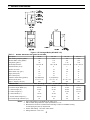
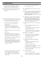
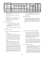
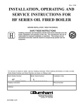
Price - $3.00
INSTALLATION, OPERATING AND
SERVICE INSTRUCTIONS FOR
HF SERIES OIL FIRED BOILER
BEFORE INSTALLATION: READ THIS MANUAL
SAVE THESE INSTRUCTIONS
Installing contractor and homeowner should read and be informed as to the
proper installation and operation of this unit. The manufacturer will not be
responsible for improper installation or operation. This manual and all
associated instruction material should be conspicuously posted near the
equipment.
For service or repairs to boiler, call your heating contractor. When seeking information on boiler, provide
Boiler Model Number and Serial Number as shown on Rating Label.
Boiler Model Number
HF ____-____
Boiler Serial Number
6_ _ _ _ _ _ _
Heating Contractor
Phone Number
Address
8143709R3-12/99
Installation Date
1
IMPORTANT INFORMATION - READ CAREFULLY
Al l boilers must be installed in a ccorda nce with National, State and Local Plumbing,
Heating and Electrica l Codes and the regulations of the serving util ities. These Codes and
Regulations may diffe r from this instruction manual. Authorities ha ving jurisdiction should
be consulted before install ations are made.
In all cas es, reference should be made to the following Standards:
All w iring on boilers installed in the U SA shall be made in a ccordance with the National
Electrical Code and/or Local Re gulations.
A.
B.
C.
A.
USA BOILERS
Current Edition of American National Standard ANSI/NFPA 31, “Installation of Oil Burning
Equipment”, for recommended installation practices.
Current Edition of American National Sta ndard ANSI /NFPA 211, “Chimne ys, Firepla ces,
Vents, and Solid Fuel Burning Appliances”, For Venting requirements.
Current Edition of American Society of Mechanical Engineers ASME CSD-1, "Controls and
Safety Devices for Automatically Fired Boilers", for assembly and operations of controls
and safety devices.
CANADIAN BOILERS
Current Edition of Canadian Standards Association CSA B139, "Installation Code of Oil
Burning Equipment", for recommended installation practices.
The following terms are used throughout this manual to bring attention to the presence of hazards of various risk levels,
or to important information concerning product life.
DANGER
CAUTION
Indicates an imminently ha zardous situation
w hich, if not avoided, will re sult in death,
serious injury or substantial property
damage.
Indic ates a potentially ha zardous situation
which, if not av oided, may result in
modera te or minor injury or property
damage.
WARNING
NOTICE
Indic ates a potentially ha zardous situation
which, if not avoide d, could re sult in death,
serious injury or substantial property
damage.
Indicates spe cial instructions on
installation, operation, or ma intenance
w hich are importa nt but not related to
personal injury ha zards.
NOTICE
This boiler has a limited warranty, a copy of w hich is printed on the back of this manual.
It is the responsibility of the installing contractor to see that all controls are correctly installed
and are operating properly when the installation is complete. The warranty for this boiler is valid
only if the boiler has been installed, maintained and operated in accordance with these
instructions.
2
DANGER
DO NOT store or use gasoline or other flammable vapors or liquids in the vicinity of this or any
other appliance.
WARNING
Improper installation, adjustment, alteration, servic e or mainte na nce can cause property
damage, personal injury or loss of life. Failure to follow all instructions in the proper order
can cause personal injury or death. Read and understand all instructions, inc luding all
those containe d in compone nt manufac turers manuals w hich are prov ided with the
appliance before instal ling, starting-up, opera ting, maintaining or servicing this applia nce.
Keep this manual and lite rature in legible condition and posted near appliance for reference
by owner and service technic ian.
This boiler requires regular maintenance and service to operate safely. Follow the instructions
contained in this manual. Installation, maintenance, and service must be performed only by an
experienced, skilled and knowledgeable installer or service agency. All heating systems should
be designed by c ompetent contrac tors and only persons k nowledge able in the la yout and
installa tion of hydronic heating systems should attempt installation of any boiler. It is the
responsibility of the installing contractor to see that all controls are correctly installed and are
operating properly w hen the installation is completed. Installation is not complete unless a
pressure relief valve is installed into the tapping located on top of appliance - See Section III of
this manual for details.
This boiler is not suitable for installation on c ombustible flooring, unless install ed with a
combustible floor shield (avai lable at extra cost). Do not ins tall boiler on carpeting.
Do not tam per wi th or alter the boiler or controls. Re tain your cont ra ctor or a compet ent
se rv ice man to assure that th e unit is p ro perly adjus ted an d main taine d.
Have Firetube s cleane d at leas t once a year - prefe rably at the start o f the he ating sea son
to re move soot a nd sca le. The inside of combustion cha mber sho uld also be cle aned and
ins pecte d at the same time .
Have Oil Burner and Controls ch ecke d at leas t once a ye ar or as may be nec ess itate d.
Do not operate unit w ith jumpere d or abs ent con tro ls or safety devices .
D o no t operate unit if any control, sw itc h, c omponent, or dev ice has b een s ubjec t to
w ate r.
3
WARNING
Appliance materials of construction, products of combustion and the fuel contain alumina, silica,
he av y me tals, carb on mon oxide, nit rogen oxides , a ldehyd es a nd/or oth er tox ic or harm ful
substances which can cause death or serious injury and which are known to the state of California
to cause cancer, birth defects and other reproductive harm. Always use proper safety clothing,
respirators and equipment when servicing or working nearby the appliance.
This boiler contains very hot water under high pressures. Do not unscrew any pipe fittings nor
attempt to disconnect any components of this boiler without positively assuring the water is cool
and has no pressure. Always w ear protective clothing and equipment when installing, starting
up or servicing this boiler to prevent scald injuries. Do not rely on the pressure and temperature
gauges to determine the temperature and pressure of the boiler. This boiler contains components
w hich become very hot w hen the boiler is operating. Do not touch any components unless they
are cool.
This appliance mus t be properly v ented and connected to an approved vent system in good
condition. D o not ope rate boiler with the absence of an unapproved ve nt s ystem.
This boiler needs fresh air for safe operation and must be installed so there are provisions for
adequate combustion and ventilation air.
The interior of the venting and air intake systems must be inspected and cleaned before the start
of the heating season and should be inspected periodically throughout the heating season for
any obstructions. Clean and unobstructed venting and air intake systems are necessary to allow
noxious fumes that could cause injury or loss of life to vent safely and will contribute toward
maintaining the boiler's efficiency.
This boiler is supplied with controls which may cause the boiler to shut down and not re-start
without service. If damage due to frozen pipes is a possibility, the heating system should
not be left unatttended in cold weather; or appropriate safeguards and alarms should be installed
on the heating system to prevent damage if the boiler is inoperative.
This boiler is designed to burn No. 2 fuel oil only. Do not use gasoline, crankcase drainings, or
any oil containing gasoline. Never burn garbage or paper in this boiler. Do not convert to any
solid fuel (i. e. wood, coal) or gaseous fuel (i. e. natural gas, LP/propane). All flammable debris,
rags, paper, wood scraps, etc., should be kept clear of the boiler at all times. Keep the boiler area
clean and free of fire hazards.
Do not operate boiler on combustible floor without a factory supplied floor shield. Concrete over
wood joists is considered combustible flooring. Do not operate on masonry floors, which may
contain moisture.
Tables of Contents
I.
General Information ............................. 5
II.
Installation Instructions ......................... 8
III.
System Start-Up ................................... 18
4
IV.
Service and Cleaning ............................ 23
V.
Repair Parts .......................................... 24
I: General Information
Figure 1: HF Packaged Boiler (HF-98/HF-173)
Ta ble 1 : WAT ER RAT ING S AND S PEC IFI CATI O NS
Description
DOE Heating Capacity (MB H)
IBR Net Water rating (MB H)
Fir ing Ra te (gal/hr)
Noz zle Spec ifi cation
Stack Dia meter (inch)
HF- 98
HF- 122
HF- 147
HF- 173
104
132
154
184
90
115
134
160
.85
1.10
1.25
1.50
.75 x 45° B
.90 x 45° B
1.00 x 45° B
1.25 x 45° B
6
6
7
7
Nu mber of Tub es
12
12
18
18
Boiler Water Cap. (gal.)
20
20
40
40
Supply S ize (FPT)
1¼
1¼
2
2
Return S ize (FPT)
1¼
1¼
2
2
4 (5 Optiona l)
4 (5 Optiona l)
5
5
8" x 8" x 15'
8" x 8" x 15'
8" x 8" x 15'
8" x 8" x 15'
450
450
720
720
Tankles s Heater S ize (gal/mi n)
Chimn ey S ize (mi n)
Approx. S hipping Wt. (lb.)
DIM ENSIO NS
M ax. W orki ng P ressu re: 30 PSI (W ater O nly)
A Overall Width (in.)
18-1/8
18-1/8
24
24
B Overall Len gth Boiler (in.)
24-1/2
24-1/2
31-3/4
31-3/4
C J ack et Height (in.)
37-3/4
37-3/4
46-3/4
46-3/4
D J acket Length (in.)
18
18
21-3/4
21-3/4
E Jacket Width (in.)
18-1/8
18-1/8
22
22
F S moke Outlet Height (in.)
25-1/4
25-1/4
30
30
33
33
39
39
G Over all Leng th w/Burner (in.)
Notes: 1. Firing rates based on 140,000 BTU per gallon of oil
2. IBR net water ratings based on a pick-up allowance of 1.15
3. Manufacturer should be consulted before selecting a boiler for installations having
unusual piping and pick-up requirements.
4. Firebox draft setting: -.02 inches water column
5. Ratings based on 13.0% CO2
5
A. INSPECT SHIPMENT carefully for any signs of damage.
2. FOR BASEMENT INSTALLATION, provide a
concrete base if floor is not perfectly level, or if
water may be encountered on floor around boiler.
1. ALL EQUIPMENT is carefully manufactured,
inspected and packed. Our responsibility ceases
upon delivery of the crated boiler to the carrier in
good condition.
3. PROVIDE SERVICE CLEARANCE of at least 48”
from the front of the jacket for servicing of burner
and removal of tankless heater.
2. ANY CLAIMS for damage or shortage of shipment
must filed immediately against the carrier by the
consignee. No claims for variances from, or
shortage in orders, will be allowed by the manufacturer unless presented within sixty (60) days after
receipt of goods.
For minimum clearances to combustible materials. See
Figure 2.
B. LOCATE BOILER in front of final position before
removing crate.
1. LOCATE so that smoke pipe connection to chimney will be short and direct. BOILER IS NOT
SUITABLE FOR INSTALLATION ON COMBUSTIBLE FLOOR unless combustible floor shield,
supplied by Burnham, is used. DO NOT install on
carpeting.
Figure 2: Minimum Clearances to Combustible Materials
NOTE:
1. Listed clearances comply with American National Standard ANSI/NFPA 31, Installation of Oil Burning Equipment.
2.
HF boilers can be installed in rooms with clearances from combustible material as listed above. Listed clearances can not be
reduced for alcove or closet installations.
3.
For reduced clearances to combustible material, protection must be provided as described in the above ANSI/NFPA 31
standard.
6
C. PROVIDE AIR SUPPLY AND VENTILATION to
then it is considered an unconfined space. If the
result is less than 50 ft3/1000 BTU per hour then the
space is considered a confined space.
accommodate proper combustion. If natural ventilation
is inadequate, provide a screened opening or duct from
the boiler room to the outside. The opening or duct
must be sized so the boiler input will not exceed 4,000
BTUH/Sq. In. of free area. If other air consuming
appliances are near the boiler, the air inlet should be
larger. Consult respective manufacturers.
4. For boiler located in an unconfined space of a
conventionally constructed building, the fresh air
infiltration through cracks around windows and
doors normally provides adequate air for combustion and ventilation.
D. VENTILATION AIR must be provided to maintain the
5. For boiler located in a confined space or an unconfined space in a building of unusually tight construction, provide outdoor air with the use of two
permanent openings which communicate directly or
by duct with the outdoors or spaces (crawl or attic)
freely communicating with the outdoors. Locate one
opening within 12 inches of top of space. Locate
remaining opening within 12 inches of bottom of
space. Minimum dimension of air opening is 3
inches. Size each opening per following:
ambient temperature at safe limits. Local and national
codes may apply and should be referenced.
1. In unconfined spaces (basement) in buildings of
conventional frame, brick, or stone construction,
infiltration normally is adequate to provide air for
ventilation.
2. In confined spaces, two permanent openings, one
near the top of the enclosure and one near the
bottom, shall be provided. Each opening shall have
a free area of not less than 1 sq. inch per 1000
BTUH of the total input of all appliances in the
space.
a. Direct communication with outdoors. Minimum
free area of 1 square inch per 4,000 BTU per hour
input of all equipment in space.
b. Vertical ducts. Minimum free area of 1 square
inch per 4,000 BTU per hour input of all equipment in space. Duct cross-sectional area shall be
same as opening free area.
c. Horizontal ducts. Minimum free area of 1 square
inch per 2,000 BTU per hour input of all equipment in space. Duct cross-sectional area shall be
same as opening free area.
Alternate method for boiler located within
confined space. Use indoor air if two permanent
openings communicate directly with additional
space(s) of sufficient volume such that combined
volume of all spaces meet criteria for unconfined
space. Size each opening for minimum free area of
1 square inch per 1,000 BTU per hour input of all
equipment in spaces, but not less than 100
square inches.
E. PROVIDE COMBUSTION AND VENTILATION AIR.
Local code provisions may apply and should be
referenced.
WARNING
Adequate combustion and ventilation air must be
provided to assure proper combustion.
6. Louvers and Grilles of Ventilation Ducts
1. Determine volume of space (boiler room). Rooms
communicating directly with the space in which the
appliances are installed, through openings not
furnished with doors, are considered a part of the
space.
a. All outside openings should be screened and
louvered. Screens used should not be smaller
than 1/4 inch mesh. Louvers will prevent the
entrance of rain and snow.
b. Free area requirements need to consider the
blocking effect of louvers, grilles, or screens
protecting the openings. If the free area of the
louver or grille is not known, assume wood
louvers have 20-25 percent free area and metal
louvers and grilles have 60-75 percent free area.
Volume(ft3) = Length(ft) x Width(ft) x Height(ft)
2. Determine total input of all appliances in the space.
Add inputs of all appliances in the space and round
the result to the nearest 1000 BTU per hour.
3. Determine type of space. Divide Volume by total
input of all appliances in space. If the result is
greater than or equal to 50 ft3/1000 BTU per hour,
c. Louvers and grilles must be fixed in the open
position, or interlocked with the equipment to
open automatically during equipment operation.
7
II. Installation Instructions
WARNING
Failure to prope rly pipe boiler ma y res ult i n improper operati on and d amage to boiler or
structu re .
Oxygen contamination of boiler wa te r w ill cause c orrosion of iron and steel boiler
c omponents, a nd c an lead to boiler failure. Burnham's Standa rd Warranty does not cover
proble ms caused by oxygen contamination of boiler wa te r or scale (lime) build-up caused
by frequent addition of w ater.
clearance from hot water piping to combustible
materials.
A. Design a piping system and install boiler which will
prevent oxygen contamination of boiler water and
frequent water additions.
a. If this boiler is used in connection with refrigeration systems, the boiler must be installed so
that the chilled medium is piped in parallel with
the heating boiler using appropriate valves to
prevent the chilled medium from entering the
boiler. See Figure 3. Also, consult I=B=R
Installation and Piping Guides.
1. There are many possible causes of oxygen contamination such as:
a. Addition of excessive make-up water as a result
of system leaks.
b. Absorption through open tanks and fittings.
b. If this boiler is connected to heating coils
located in air handling units where they may be
exposed to refrigerated air, the boiler piping
must be equipped with flow control valves to
prevent gravity circulation of boiler water
during the operation of the cooling system.
c. Oxygen permeable materials in the distribution
system.
2. In order to insure long product life, oxygen sources
should be eliminated. This can be accomplished by
taking the following measures:
a. Repairing system leaks to eliminate the need for
addition of make-up water.
c. If boiler is used with an Alliance™ IndirectFired Domestic Water Heater, install the
Alliance as a separate heating zone. Refer to
the Alliance Installation, Operating, and Service
Instructions for additional information.
b. Eliminating open tanks from the system.
c. Eliminating and/or repairing fittings which
allow oxygen absorption.
d. Use a system bypass if the boiler is to be
operated in a system which has a large volume
or excessive radiation where low boiler water
temperatures may be encountered (i.e. converted
gravity circulation system, etc.) The bypass
should be the same size as the supply and
return lines with valves located in the bypass
and return line as illustrated in Figure 4 in order
to regulate water flow for maintenance of higher
boiler water temperature. Set the bypass and
return valves to a half throttle position to start.
Operate boiler until the system water temperature reaches its normal operating range. Adjust
the valves to maintain 180°F to 200°F boiler
water temperature and greater the 120°F return
temperature. Adjust both valves simultaneously.
Closing the boiler return valve while opening
the bypass valve will raise the boiler return
temperature. Opening the boiler return valve
while closing the by-pass valve will lower the
boiler return temperature.
d. Use of non-permeable materials in the distribution system.
e. Isolating the boiler from the system water by
installing a heat exchanger.
WARNING
System supply and return piping must
be connected to correct boiler pipe.
Burnham re commends s izing the
s ystem circulator to s upply sufficient
flow (GPM) to allow a 20 °F temperature
differential in the s ystem. When s izing
the system circulator, the pressure
drop of all radiators, baseboard and
radiant tubing and a ll connecting
piping must be considered.
3. Connect System supply and return piping to boiler.
See Figures 8 and 9. Also, consult I=B=R Installation and Piping Guides. Maintain minimum ½ inch
e. A water boiler installed above radiation level
must be provided with a low water cutoff device
as part of the installation.
8
B. Install Pressure Relief Valve. See Figures 8 and 9.
Pressure Relief Valve must be installed with spindle in
the vertical position. Installation of the relief valve must
be consistent with ANSI/ASME Boiler and Pressure
Vessel Code, Section IV.
Figure 3: Recommended Piping for Combination
Heating and Cooling (Refrigeration) System
C. Install Drain Valve in return piping. See Figures 8
and 9.
D. Oil, grease, and other foreign materials which accumulate in new hot water and a new or reworked system
should be boiled out, and then thoroughly flushed. A
qualified water treatment chemical specialist should be
consulted for recommendations regarding appropriate
chemical compounds and concentrations which are
compatible with local environmental regulations.
E. After the boiler and system have been cleaned and
flushed, and before refilling the entire system add
appropriate water treatment chemicals, if necessary, to
bring the pH between 7 and 11.
F. CONNECT TANKLESS HEATER PIPING AS
SHOWN IN FIGURE 1. See Table 1 for Tankless
Heater Rating.
Figure 4: Recommended System Bypass Piping
Figure 5: Schematic Tankless Heater Piping
9
heater but to piping and fixtures plus the many other
benefits derived from soft water.
G. INSTALL SMOKEPIPE — The HF should be vented
into a fireclay tile-lined masonry chimney or chimney
constructed from type L vent or a factory built chimney
that complies with the type HT requirements of UL103.
The chimney and vent pipe shall have a sufficient draft
at all times, to assure safe proper operation of the boiler.
See Figure 6 for recommended installation.
1. Install a draft regulator following the instructions
furnished with the regulator. See Figure 7 for
alternate draft regulator locations.
2. Consider the chimney overall. Chimneys that have a
high heat loss may become less suitable as the heat
loss of the home goes down and the efficiency of
the boiler installed goes up. Most homes have a
chimney appropriate for the fuel and the era in which
the home was built. That may have been a coal fired
or an inefficient oil fired boiler built into a home
without insulation or storm windows. With increasing fuel prices that home probably has been insulated and fitted with storm windows so that the heat
loss of the home has been reduced. This requires
less fuel to be burned and sends less heat up the
chimney.
A new boiler probably has a higher efficiency than
the boiler being replaced. That probably means that
the stack temperature from the new boiler will be
lower than that from the old boiler and with less
room air being drawn up the chimney to dilute the
stack gases. The combination of a large uninsulated
chimney, reduced firing rate, reduced firing time,
lower stack temperature and less dilution air can, in
some cases, contribute to the condensing of small
amounts of water vapor in the chimney. Such
condensation, when it occurs, can cause chimney
deterioration. In extreme cases, condensed water
may be visible on the outside of the breeching or
chimney. In those extreme cases, the chimney may
have to be lined to insulate the chimney and thus
prevent the condensation. The addition of dilution
air into the chimney may assist in drying the
chimney interior surfaces.
A massive chimney on a cold, or exposed outside
wall may have produced adequate draft when it was
fired with a higher input and greater volumes of
heated gases. With reduced input and volume, the
draft may be severely affected. In one instance our
research showed a new chimney of adequate sizing
produced only -.035" W.C. after 30 minutes of
continuous firing at 13.0% CO2. Outside wall
chimneys take longer to heat up and can have .00"
W.C. draft at burner startup. You may have to
consider a special alloy chimney flue liner with
insulation around it and a stabilizing draft cap or
even a draft inducing fan in severe cases.
THE FOLLOWING GUIDELINES SHOULD BE FOLLOWED
WHEN PIPING THE TANKLESS HEATER:
1. FLOW REGULATION — If flow through the heater
is greater than its rating, the supply of adequate hot
water may not be able to keep up with the demand.
For this reason a flow regulator matching the heater
rating should be installed in the cold water line to
the heater. The flow regulator should preferably be
located below the inlet to the heater and a minimum
of 3’ away from the inlet so that the regulator is not
subjected to excess temperatures that may occur
during “off” periods when it is possible for heat to
be conducted back through the supply line. The
flow regulator also limits the flow of supply water
regardless of inlet pressure variations in the range of
20 to 125 psi.
2. TEMPERING OF HOT WATER — Installation of an
automatic mixing valve will lengthen the delivery of
the available hot water by mixing some cold water
with the hot. This prevents the possibility of
scalding hot water at the fixtures. In addition,
savings of hot water will be achieved since the user
will not waste as much hot water while seeking a
water temperature. Higher temperature hot water
required by dishwashers and automatic washers is
possible by piping the hot water from the heater
prior to entering the mixing valve. The mixing valve
should be “trapped” by installing it below the cold
water inlet to heater to prevent lime formation in the
valve. Refer to Figure 5.
3. FLUSHING OF HEATER — All water contains some
sediment which settles on the inside of the coil.
Consequently, the heater should be periodically
backwashed. This is accomplished by installing
hose bibs as illustrated and allowing water at city
pressure to run into hose bib A, through the heater,
and out hose bib B until the discharge is clear. The
tees in which the hose bibs are located should be
the same size as heater connections to minimize
pressure drop.
4. HARD WATER — A water analysis is necessary to
determine the hardness of your potable water. This
is applicable to some city water and particularly to
well water. An appropriate water softener should be
installed based on the analysis and dealer’s recommendation. This is not only beneficial to the tankless
10
3. For the same reasons as in (2.) above, heat extractors
mounted into the breeching are not recommended.
Figure 6: Recommended Smokepipe Arrangement and Chimney Requirements
Figure 7: Proper and Improper Locations of Draft Regulator
11
12
Figure 8: Recommended Boiler Piping for Circulator Zoned Heating Systems
13
Figure 9: Boiler Piping for Zone Valve Zoned Heating Systems
DANGER
Positively assure all electrical connecti ons are unpow ered before attempting installation or
service of elec tric al components or connections of the boiler or bui lding. Lock out all ele ctrical
boxes wi th pa dlock once power is turned off.
WARNING
Failure to properly wire electrical connections to the boiler may result in serious physical
harm.
Electrical pow er may be from more than one source. Make sure all power is off before
attempting any electrical work.
Each boiler must be protected with a properly sized fused disconnect.
Never jump out or make inoperative any safety or operating controls.
The w iring diagrams contained in this manual are for reference purposes only. Refer to the
w iring diagram of any controls used with the boiler. Read, understand and follow all wiring
instructions supplied with the controls.
H. Electrical
1. Install wiring and electrically ground boiler in
accordance with requirements of the authority
having jurisdiction, or in absence of such requirements the National Electrical Code, ANSI/NFPA
70, and/or the CSA C22.1 Electric Code.
5. Single Zone System – Connect the system circulator wire leads to the proper locations on the
Aquastat control, L8124C/L8148A. See Figure 10 or
11. Connect the thermostat to the ‘T-T’ terminals on
the L8124C/L8148A control. Set thermostat heat
anticipator settings to 0.60 amps.
2. A separate electrical circuit should be run from the
main electrical service with a fused disconnect
switch in the circuit.
6. Conventional Circulator Zoned System – Read,
understand and follow all of the instructions
provided with the Honeywell R8888 control.
3. Wiring should conform to Figure 10 and/or 11.
7. Conventional Zone Valve Zoned System – Locate
C1 and C2 inside the L8124C Honeywell control.
Connect the two (2) terminals to the system
circulator wire leads, supplied with boiler.
I. System Controls and Wiring
1. Refer to National Electric Code or Local Electric
Codes for proper size and type of wire required.
Follow Code.
Connect the H1 and H2 terminals inside the R8889
to the ‘T-T’ terminals in the L8124C Honeywell
Control.
2. Use anti-short bushings on all wiring passing
through boiler jacket, junction boxes and/or control
boxes.
Connect the thermostat of each zone and the
circulator for that zone to R8889 panel. If an
Alliance™ indirect water heater is used, connect
the Alliance thermostat and circulator to the Zone 1
terminals of the R8889. Set thermostat anticipator
settings to 0.12 amps.
3. Use armored cable (BX) over all exposed line
voltage wiring.
4. If an Alliance™ indirect water heater is used, use
priority zoning. Do not use priority zoning for
Hydro-Air Systems.
14
Figure 10: Wiring Diagram for Water Boilers with Beckett AFG Burner and Controls, without Tankless Heater
SEQUENCE OF OPERATION
A call for heat by the thermostat energizes the L8148A control which in turn energizes the R4184D primary control to turn on the
burner. If burner ignites within approximately 45 seconds and the cad cell sees flame, the burner will continue to operate until the call
for heat is satisfied or the setting of the high limit is reached. The circulator will operate as long as the thermostat is calling for heat. If
the thermostat is not satisfied and the high limit is reached, the circulator will continue to operate, and the burner will stop until the high
limit is closed by a drop in boiler water temperature.
Figure 11: Wiring Diagram for Water Boilers with Beckett AFG Burner and Controls, with Tankless Heater
SEQUENCE OF OPERATION
A call for heat by the thermostat energizes the L8124C control which in turn energizes the R4184D primary control to turn on the burner. If
burner ignites within approximately 45 seconds and the cad cell sees flame the burner will continue to operate until the call for heat is
satisfied. The circulator will also operate when the thermostat calls for heat if the boiler water temperature is up to the setting of the low limit
in the L8124C control. If boiler water temperature is below the low limit setting the burner will operate but the circulator will not, giving
preference to the domestic hot water demand.
On call for heat by the thermostat the burner will continue to operate until the thermostat is satisfied or the setting of the high limit is
reached. If the thermostat is not satisfied when the high limit is reached the burner will stop but the circulator will continue to operate until
the thermostat is satisfied. Any time the boiler water temperature drops below the setting of the low limit the burner will be energized in
order to maintain domestic water temperature.
15
J. Oil Piping
K. Single-pipe Oil Lines
1. Use flexible oil line(s) so that burner can be
removed without disconnecting the oil supply.
1. Standard burners are provided with single-stage
3450 rpm fuel units with the bypass plug removed
for single-pipe installations.
2. A supply line fuel oil filter is recommended as a
minimum for all firing rates but a pleated paper
fuel oil filter is recommended for the lowest firing
rate application to prevent nozzle fouling.
2. The single-stage fuel unit may be installed singlepipe with gravity feed or lift. Maximum allowable
lift is 8 feet. See Figure 12.
3. Use Flared fittings only. Do not use compression
fittings.
NOTICE
4. Use of a high efficiency micron filter (Garber or
equivalent) in addition to conventional filter is
highly recommended.
Oil piping must be absolutely airtight or
leaks or loss of prime may result. Bleed line
and fuel unit completely.
Figure 12: Single-Pipe Installation
16
TABLE 2: SINGLE STAGE UNITS (3450 RPM)
TWO PIPE SYSTEMS
Lift "H"
(See Figure)
TABLE 3: TWO-STAGE UNITS (3450 RPM)
TWO-PIPE SYSTEMS
Maximum Length of Tubing
"H" +"R" (See Figure)
3/8" OD
Tubing (3 GPH)
1/2" OD
Tubing (3 GPH)
0'
84'
100'
1'
78'
100'
2'
73'
3'
Lift "H"
(See Figure)
Maximum Length of Tubing
"H" + "R" (See Figure)
3/8" OD
Tubing
1/2" OD
Tubing
0'
93'
100'
100'
2'
85'
100'
68'
100'
4'
77'
100'
4'
63'
100'
6'
69'
100'
5'
57'
100'
8'
60'
100'
6'
52'
100'
10'
52'
100'
7'
47'
100'
12'
44'
100'
8'
42'
100'
14'
36'
100'
9'
36'
100'
16'
27'
100'
10'
31'
100'
18'
---
76'
11'
26'
100'
12'
21'
83'
13'
---
62'
14'
---
41'
L. Two-Pipe Oil Lines
1. For two-piped systems, where more lift is required,
the two-stage fuel unit is recommended. Table 2
(single-stage) and Table 3 (two-stage) show
allowable lift and lengths of 3/8 inch and 1/2 inch
OD tubing for both suction and return lines. Refer
to Figure 13.
Figure 13: Two-Pipe Installation
17
III. System Start-Up
10. Open isolation valve in boiler supply piping.
A. Verify that the venting, water piping, oil piping, and
electrical system are installed properly. Refer to
installation instructions contained in this manual.
11. Remove hose from bib cock.
D. CONFIRM that the boiler and system have no water
B. Confirm all electrical, water and oil supplies are turned
leaks.
off at the source and that the vent is clear from
obstructions.
E. CHECK CONTROLS, WIRING AND BURNER to be
sure that all connections are tight and burner is rigid.
Verify that all electrical connections have been
completed, fuses installed, that the oil tank is filled and
oil lines have been tested.
F. LUBRICATION. Follow instruction on burner and
circulator label to lubricate, if oil lubricated. Most
motors currently used on residential type burners
employ permanently lubricated bearings and thus do
not require any field lubrication. Water lubricated
circulators do not need field lubrication.
C. Fill entire heating system with water and vent air from
system. Use the following procedure on a Series Loop
or multi-zoned system installed as per Figure 8 or 9.
1. Close isolation valve in boiler supply piping.
G. SET CONTROLS with burner service switch turned
2. Isolate all circuits by closing zone valves or
balancing valves.
“OFF”.
1. SET ROOM THERMOSTAT about 10° above
room temperature.
3. Attach a hose to bib cock located just below
isolation valve in boiler supply piping. (Note Terminate hose at a suitable floor drain or outdoor
area).
2. PRESS RED RESET BUTTON on R4184D Oil
Primary Control and release.
4. Starting with one circuit at a time, open zone valve
or valve.
3. SET HIGH LIMIT dial on L8124C/L8148A at
temperature to suit requirements of installation.
5. Open bib cock.
H. REMOVE GUN ASSEMBLY
6. Open fill valve (Make-up water line should be
located directly after isolation valve in boiler supply
piping between air scoop and expansion tank).
1. Check nozzle size, head size, gun setting, and
positioning of electrodes. This information is
shown in Figure 14, and Table 4.
7. Allow water to flow into drain until discharge from
hose is bubble free for 30 seconds.
2. Reinstall gun assembly.
I. VERIFY OIL BURNER SETTINGS BEFORE
8. When zone is completely purged of air, close zone
valve or balancing valve. Open the zone valve for
the next zone to be purged. Repeat this step until
all zones have been purged. At completion, open
all zone valves or valves.
STARTING
1. BURNER AIR BAND AND AIR SHUTTER
SETTINGS, see Tables 4.
2. OPEN ALL OIL LINE VALVES.
3. Attach a plastic hose to fuel pump vent fitting and
provide a container to catch the oil.
4. REMOVE GAUGE PORT PLUG from fuel pump
and install pressure gauge.
J. START OIL BURNER
9. Close bib cock, continue filling the system until the
pressure gauge reads 12 psig. Close fill valve.
(Note - If make-up water line is equipped with
pressure reducing valve, system will automatically
fill to 12 psig.
1. Open vent fitting on fuel pump.
2. TURN ‘ON’ BURNER service switch and allow
burner to run until oil flows from vent fitting in a
18
Table 4: Beckett AFG
Boiler
Model
No.
Firing
Rate
(GPH)
Burner
HF98
.85
HF122
Nozzle Specifications
M anufacturer
Size
Angle
Type
A FG
HA GO
.75
45°
B
1.10
A FG
HA GO
.90
45°
HF147
1.25
A FG
HA GO
1.0
HF173
1.50
A FG
HA GO
1.25
Static
Plate
Air Settings
Head
Head
Setting
Shutter
Band
3-3 /8"U
8
0
L1
0
B
3-3 /8"U
10
2
L1
0
45°
B
2-3 /4"U
10
0
V1
0
45°
B
2-3 /4"U
10
2
V1
2
SOLID stream without air bubbles for approximately 10 seconds.
4. TURN “OFF” BURNER and remove pressure
gauge. Install gauge port plug and tighten. Start
burner again.
3. Close vent fitting and burner flame should start
immediately.
M. FLAME FAILURE
4. If the burner does not start immediately, check the
manual overload switch on the motor, if so
equipped, and the safety switch on the burner
primary control.
The HF boiler controls operate the burner automatically. If for unknown reasons the burner ceases to fire
and the rest button on the primary control has tripped,
the burner has experienced ignition failure. Before
pressing the rest button, call your serviceman immediately.
K. ADJUST OIL PRESSURE
1. Locate oil pressure adjusting screw and turn
screw until Pressure Gauge reads the correct
pump pressure required for the specific boiler.
Refer to Table 4 .
2. DO NOT REMOVE PRESSURE GAUGE until
later.
L. OTHER ADJUSTMENTS
N. CHECK FOR CLEAN CUT OFF OF BURNER
1. ADJUST THE AIR BAND AND/OR AIR SHUTTER.
1. AIR IN THE OIL LINE between fuel unit and
nozzle will compress when burner is on and will
expand when burner stops, causing oil to squirt
from nozzle at low pressure as burner slows down
and causing nozzle to drip after burner stops.
Usually cycling the burner operation about 5 to 10
times will rid oil line of this air.
Beckett Burners:
a. Adjust air supply by loosening lock screws and
moving the air shutter and if necessary the air
band. Refer to Table 4 preliminary settings.
2. ADJUST DRAFT REGULATOR for a draft of
-.02” (water gauge) over the fire after chimney has
reached operating temperature and while burner is
running.
2. IF NOZZLE CONTINUES TO DRIP, repeat step
N.1. If this does not stop the dripping, remove cut
off valve and seat, and wipe both with a clean cloth
until clean. Then replace and readjust oil pressure.
If dripping or after burn persist replace fuel pump.
3. READJUST AIR BANDS on burner for a light
orange colored flame while draft over the fire is
-.02” w.c. Use a smoke test and adjust air for
minimum smoke (not to exceed #1) with a minimum of excess air. Make final check using suitable
instrumentation to obtain a CO2 of 11.5 to 12.5%
with draft of -.02” w.c. in fire box. These settings
will assure a safe and efficient operating condition.
If the flame appears stringy instead of a solid flame,
try another nozzle of the same type. Flame should
be solid and compact. After all adjustments have
been made, recheck for a draft of -.02” w.c. over the
fire.
O. HINTS ON COMBUSTION
a. NOZZLES— Although the nozzle is a relatively
inexpensive device, its function is critical to the
successful operation of the oil burner. The
selection of the nozzle supplied with the HF
boiler is the result of extensive testing to obtain
the best flame shape and efficient combustion.
Other brands of the same spray angle and spray
pattern may be used but may not perform at the
expected level of CO2 and smoke. Nozzles are
19
See Manila folder in file titled “HF”
Figure 14: Electrode / Head Setting
delicate and should protected from dirt and
abuse. Nozzles are mass produced and can vary
from sample to sample. For all of those reasons
a spare nozzle is a desirable item for a serviceman to carry.
c. FUEL LEAKS— Any fuel leak between the pump
and the nozzle will be detrimental to good
combustion results. Look for wet surfaces in the
air tube, under the ignitor, and around the air
inlet. Any such leaks should be repaired as they
may cause erratic burning of the fuel and in the
extreme case may become a fire hazard.
b. FLAME SHAPE — Looking into the combustion chamber through the flame plug hole, the
flame should appear straight with no sparklers
rolling up toward the top of the chamber. If the
flame drags to the right or left, sends sparklers
upward or makes wet spots on the combustion
chamber, the nozzle should be replaced. If the
condition persists look for fuel leaks, air leaks,
water or dirt in the fuel as described below.
d. AIR LEAKS— Any such leaks should be
repaired, as they may cause erratic burning of
the fuel and in extreme cases may become a fire
hazard.
There may be many possible causes of leaks in
oil lines such as:
20
i.
Fitting leaks due to misflared tubing or
damaged fitting.
ii.
Fuel line leak due to crushed or bent tubing.
i. HIGH ALTITUDE INSTALLATIONS
Typically, the rule to use for high altitudes is to
increase the air supply by 4% per each 1000 ft.
above 2000 ft. altitude from sea level. This
means that the air setting will have to be higher
than the calibration marks in proportion to the
altitude. Use instruments and set for 11.5 to
12.5% CO2.
iii. Filter connection leaks.
iv. Tank connection leaks.
The following actions can eliminate air leaks:
i.
ii.
Bleed pump as detailed in System Start-Up
Section of this manual.
j. START-UP NOISE — Late ignition is the cause
of start-up noises. If it occurs recheck for
electrode settings, flame shape, air or water in the
fuel lines.
Replace flare fittings.
iii. Replace oil supply line.
iv. Repair oil filter leaks
v.
k. SHUT DOWN NOISE — If the flame runs out of
air before it runs out of fuel, an after burn with
noise may occur. That may be the result of a
faulty cut-off valve in the fuel pump, or it may be
air trapped in the nozzle line. It may take several
firing cycles for that air to be fully vented
through the nozzle. Water in the fuel or poor
flame shape can also cause shut down noises.
Replace or repair tank fittings.
e. GASKET LEAKS— If 11.5% to 12.5% CO2
with a #1 smoke cannot be obtained in stack,
look for air leaks around the canopy seal. Such
air leaks will cause a lower CO2 reading in the
stack. The smaller the firing rate the greater
effect an air leak can have on CO2 readings.
f. DIRT— A fuel filter is a good investment.
Accidental accumulation of dirt in the fuel
system can clog the nozzle strainer and produce
a poor spray pattern from the nozzle.
P. TEST CONTROLS
g. WATER— Water in the fuel, in large amounts,
will stall the fuel pump. Water in the fuel
pump, in smaller amounts, will cause excessive
wear on the pump, but more importantly water
does not burn. It chills the flame, causes smoke,
and allows unburned fuel to pass through the
combustion chamber and clog the flueways of
the boiler.
1. CHECK THERMOSTAT OPERATION. Raise and
lower thermostat setting as required to start and
stop burner.
2. VERIFY PRIMARY CONTROL SAFETY FEATURES using procedures outlined in Instructions
furnished with control (See back of Control Cover)
or Instructions as follows:
a. Simulate flame failure:
h. COLD OIL— If the oil temperature approaching
the fuel pump is 40°F or lower, poor combustion
or delayed ignition may result. Cold oil is harder
to atomize at the nozzle. Thus, the spray droplets
get larger and the flame shape gets longer. An
outside fuel tank that is above grade or has fuel
lines buried in the ground above the frost line is a
good candidate for cold oil. The best solution is
to place the tank and oil lines in the ground
below the frost line.
•
•
•
21
Follow the starting procedure to turn on the
burner.
Close the hand valve in the oil supply line.
Safety switch should lock out in approximately 15 seconds. Ignition should stop
and oil valve should close. Blower will stop
after postpurge period.
•
c. Burner should stop when water level drops below
low water cutoff probe. Verify limit, thermostat or
other controls have not shut off boiler.
Push red reset button to reset safety switch.
b. Simulate ignition failure:
•
•
•
Follow the starting procedure to turn on the
burner, but do not open the oil supply hand
valve.
Safety switch should lock out in approximately 15 seconds. Ignition and motor
should stop and oil valve should close.
Push red reset button to reset safety switch.
d. Adjust thermostat to lowest setting. Refill boiler.
Q. FREQUENT WATER ADDITION
c. Simulate power failure:
•
•
•
•
Follow the starting procedure to turn on the
burner.
With the burner running, turn off the power
to the system by tripping the circuit breaker
or removing the fuse.
Burner should stop.
Restore power. Burner should start.
A leaky system will increase the volume of make-up
water supplied to the boiler which can significantly
shorten the life of the boiler. Entrained in make-up water
are dissolved minerals and oxygen. When the fresh,
cool make-up water is heated in the boiler the minerals
fall out as sediment and the oxygen escapes as a gas.
Both can result in reduced boiler life. The accumulation
of sediment can eventually isolate the water from
contacting the steel. When this happens the steel in
that area gets extremely hot and eventually cracks. The
presence of free oxygen in the boiler creates a corrosive
atmosphere which, if the concentration becomes high
enough, can corrode the steel through from the inside.
Since neither of these failure types are the result of a
manufacturing defect the warranty does not apply.
Clearly it is in everyone’s best interest to prevent this
type of failure. The maintenance of system integrity is
the best method to achieve this.
3. VERIFY HIGH LIMIT OPERATION.
a. Adjust thermostat to highest setting.
b. Observe temperature gauge. When temperature
is indicated, adjust limit to setting below observed temperature. Burner should stop.
c. Adjust limit to setting above observed temperature. Burner should start.
d. Adjust thermostat to lowest setting. Adjust limit
to desired setting.
4. CHECK LOW WATER CUTOFF (if so equipped).
a. Adjust thermostat to highest setting.
b. With boiler operating, open drain valve and
slowly drain boiler.
22
IV. Service and Cleaning
WARNING
All bo iler s erv ic e and clea ning mus t b e c omp let ed with burne r s erv ic e s witc h tu rned off .
Boile rs equ ippe d w i th b urner sw in g do or ha ve a pote ntial ha zard w hi ch ca n c aus e sev er e
prop erty da ma ge, pe rson al in jury or los s of l if e if i gnore d. Befo re r emov in g bu rner door,
turn off se rvice sw it ch to b oiler to p rev ent ac ciden tal firin g of burn er o uts ide th e
comb ust ion chambe r. Be s ure to tig hte n bur ner door fas te ners c omplete ly w hen se rvice is
comp leted .
BE CAREFUL not to damage insulation piece.
Inspect front door insulation board and combustion chamber insulation board for damage.
Replace any damaged pieces.
NOTICE
BUR NER S HU TD O WN : O p e n S e rv ic e
Switch to turn off burner.
4. REPLACE FIREDOOR
CAUTION: Do not start burner unless burner door is
securely closed. Replace door, install fasteners, and
tighten securely. Door should be parallel to
tubesheet when viewed from top and sides.
Manual Oil Supply Valve should be closed
and Electric Service to boiler turned off if
boiler will not be operated for an extended
period of time.
C. Burner.
A. General. Inspection, service and cleaning should be
1. Replace the oil supply line filter.
conducted annually. Turn off electric power and close
oil supply valve while conducting service or maintenance.
2. Remove and clean the pump strainer (if applicable).
3. Replace the nozzle with an equivalent nozzle. See
Table 4.
B. Firetubes and Combustion Chamber.
4. Clean and inspect the electrodes for damage,
replacing any that are cracked or chipped.
1. CLEAN THE FIRETUBES
a. For access to fireside of boiler, remove fasteners
holding flue box panel closed.
5. Clean the combustion head of all lint and soot.
b. Using a 1 1/2" diameter wire brush (30" handle),
clean firetubes.
7. Remove and clean the cad cell.
6. Inspect the transformer cables and connectors.
8. Clean the blower wheel and the air control of any
lint.
c. Remove fasteners holding burner door. Carefully
remove door with burner still attached.
9. Check all wiring for secure connections or insulation breaks.
2. CLEAN THE COMBUSTION CHAMBER
Using wire or fiber bristle brush, clean inside of
combustion chamber.
10. Re-adjust the burner as detailed in Section III:
System Start-up, Paragraph I.
3. AFTER CLEANING
D. Controls. Test Controls for proper operation as detailed
a. Vacuum debris inside combustion chamber and
vacuum remaining fireside of boiler as necessary.
in Section III: System Start-up, Paragraph G.
23
V. Repair Parts
NOTE: When ordering parts always give the serial number and model number shown on the boiler. Also provide the name of
the part(s) shown below:
Figure 15: HF Series Bare Boiler
24
ITEM NO.
DES CRIPTION
PART NUM BER
1
Rear Smo ke b ox
61137004
61147005
2
Ja cket - Lo wer Re ar
70 437033
70 437042
3
S hell
8 103701
8 103702
4
Jacket - Right S ide Panel
70 437031
70 437040
5
Front Flue B ox
61137009
61137010
6
Flue B ox Frame Ins ulation
61137009
61137010
D16850
D16800
7
Flue B ox Do or w/ Ins ulation
I 21350
I21400
I 21325
I21400
70 437038
70 437047
8
Com bustion Ch amber Floor Ins ulation
9
Jacket - Lower Front P anel
10
Burn er Do or
D15700
D15800
11
Burner Door Ins ulation
I 21300
I21375
12
Ja cket - Le ft S ide P anel
70 437032
70 437041
Ja cket - Top Le ft S ide Panel
604 370361
604 370451
Jac ket - To p Right S ide Panel
704 370371
704 370461
13
14
Bu rner Spac er Plate
NOT S HOWN
Jac ket - Upper Front
70 237001
70 437034
25
704 370432
26
Figure 16: Beckett AFG Oil Burner Repair Part
For replacement oil burner parts, contact your wholesaler or the burner manufacturer: R.W. Beckett Co., P.O. Box 1289, Elyria, OH 44036
(216) 327-1060 or (800) OIL BURN(645-2876)
BECKETT BURNER PARTS LIST FOR RSA SERIES STEEL BOILERS
FOR REPLACEMENT OIL BURNER PARTS, CONTACT YOUR WHOLESALER OR THE BURNER
MANUFACTURER:
R. W. BECKETT CORP.
38251 CENTER RIDGE RD.
P. O. BOX 1289
ELYRIA, OHIO 44036
1-800-645-2876
NOTE: When ordering parts always give the serial and model numbers shown on the boiler and burner. Also, provide the
name of the part(s) and part(s) number as listed below.
Boiler Model
Burner Model
Air Tube Com bination
1)
HF-96
AFG
AFG50M B
HF-122
HF-147
AFG
AFG
A FG50M BI AFG70MDI
HF-173
AFG
AFG70MDI
Spec. No.
NY1101
NY1101
NY1108
NY1108
A ir Band
3492B KA
3492B KA
3492B KA
3492B KA
4150
4150
4150
4150
Air Band Nut
Air Band Sc rew
4198
4198
4198
4198
3709BK
3709BK
3709BK
3709BK
Air Shutter Sc rew
4198
4198
4198
4198
6)
Blower
2999
2999
2999
2999
7)
Bulkhead Fitting
3488
3488
3488
3488
8)
Bulkhead Fitting Locknut
3666
3666
3666
3666
9)
Connector Tube Assembly
5636
5636
5636
5636
10) Coupling
2454
2454
2454
2454
11) Electrode Clamp
149
149
149
149
Electrode Clamp Screw
4219
4219
4219
4219
12) Electrode Insulator Assembly
5780
5780
5780
5780
15) Spider Spacer Assembly
5503
5503
5503
5503
16) Escutcheon Plate
3493
3493
3493
3493
3146806
3146806
3146806
3146806
31498
31498
31498
31498
2)
A ir Shutter
18) Flange and Air Tube Assembly
Gasket
19) Head
5912
5912
5913
5913
Head Screws
4221
4221
4221
4221
Hole Plug
2139
2139
2139
2139
20) Housing Assembly w/Inlet Bell
5624
5624
5624
5624
21) Motor
2456
2456
2456
2456
22) Nozzle Adapter
213
213
213
213
NL50MB
NL50MB
NL50MD
NL50MD
23) Nozzle Line Electrode
Assembly
25) Pump
2460
2460
2460
2460
27) Static Plate
3384
3384
3383P
3383P
28) Ignitor
7440
7440
7440
7440
29) Ignitor Hinge Screw
4217
4217
4217
4217
30) Ignitor Holding Screw
4198
4198
4198
4198
31) Ignitor Gasket Kit
51304
51304
51304
51304
32) Wire Guard
3345
3345
3345
3345
33) Baffle
N/A
N/A
N/A
N/A
27
28