1
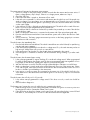
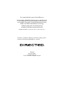
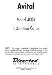
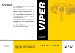
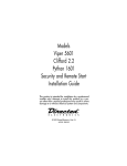
Installation Guide Keyless Entry Remote Start 4103, 4-button series This product is intended for installation by a professional installer only! Attempts to install this product by a person other than a trained professional may result in severe damage to a vehicle’s electrical system and components. © 2012 Directed. Vista, CA N4103 2012 01 Bitwriter®, Code Hopping™, Doubleguard®, ESP™, FailSafe®, Ghost Switch™, Learn Routine™, Nite-Lite®, Nuisance Prevention® Circuitry, Revenger®, Silent Mode™, Soft Chirp®, Stinger®, Valet®, Vehicle Recovery System®, VRS®, and Warn Away® are all Trademarks or Registered Trademarks of Directed Electronics. The Bitwriter® (p/n 998U) requires chip version 2.7 or newer to program this unit. Bitwriters with a date code of 6a or older require an IC upgrade (p/n 998M). Some Bitwriters with a date code of 6B do not require the IC upgrade, refer to tech tip # 1112 for more information. Contents Warning! Safety first........................................................................................................................ 4 Wiring diagram............................................................................................................................... 5 Wiring connections.......................................................................................................................... 5 Main Harness (H1), 9-pin connector............................................................................................. 5 Door Lock - 3 pin connector......................................................................................................... 6 Heavy Gauge Relay (H2), 6-pin connector.................................................................................... 6 Satellite harness - 4-pin connector................................................................................................. 6 Remote Start harness (H3) 5-pin connector.................................................................................... 6 Tach Learning.................................................................................................................................. 7 Virtual Tach..................................................................................................................................... 7 Neutral safety switch interface........................................................................................................... 8 Testing the neutral safety switch.................................................................................................... 8 Remote start shutdown diagnostics..................................................................................................... 9 Remote programming....................................................................................................................... 9 Programming system features........................................................................................................... 10 Feature menus............................................................................................................................... 11 Menu 1 .................................................................................................................................. 11 Menu 2 .................................................................................................................................. 13 Red 4-pin port, Bitwriter/ESP2 or D2D programming................................................................... 14 Bitwriter only options...................................................................................................................... 15 Bitwriter feature descriptions...................................................................................................... 15 Basic remote functions.................................................................................................................... 16 Reset and deletion.......................................................................................................................... 17 Troubleshooting: Keyless entry......................................................................................................... 17 Troubleshooting: Remote start.......................................................................................................... 17 Warning! Safety first The following safety warnings must be observed at all times: • Due to the complexity of this system, installation of this product must only be performed by an authorized Directed Electronics dealer. • When properly installed, this system can start the vehicle via a command signal from the remote control. Therefore, never operate the system in an area that does not have adequate ventilation. The following precautions are the sole responsibility of the user; however, authorized Directed Electronics dealers should: • Never use a test light or logic probe when installing this unit. Always use a multimeter. • Never operate the system in an enclosed or partially enclosed area without ventilation (such as a garage). • When parking in an enclosed or partially enclosed area or when having the vehicle serviced, the remote start system must be disabled using the installed toggle switch. It is the user’s sole responsibility to properly handle and keep out of reach from children all remote controls to assure that the system does not unintentionally remote start the vehicle. USER MUST INSTALL A CARBON MONOXIDE DETECTOR IN OR ABOUT THE LIVING AREA ADJACENT TO THE VEHICLE. ALL DOORS LEADING FROM ADJACENT LIVING AREAS TO THE ENCLOSED OR PARTIALLY ENCLOSED VEHICLE STORAGE AREA MUST REMAIN CLOSED AT ALL TIMES. Use of this product in a manner contrary to its intended mode of operation may result in property damage, personal injury, or death. Except when performing the Safety Check outlined in this installation guide, (1) Never remotely start the vehicle with the vehicle in gear, and (2) Never remotely start the vehicle with the keys in the ignition. The user is responsible for having the neutral safety feature of the vehicle periodically checked, wherein the vehicle must not remotely start while the car is in gear. This testing should be performed by an authorized Directed Electronics dealer in accordance with the Safety Check outlined in this product installation guide. If the vehicle starts in gear, cease remote start operation immediately and consult with the user to fix the problem immediately. After the remote start module has been installed, test the remote start module in accordance with the Safety Check outlined in this installation guide. If the vehicle starts when performing the Neutral Safety Shutdown Circuit test, the remote start unit has not been properly installed. The remote start module must be removed or properly reinstalled so that the vehicle does not start in gear. All installations must be performed by an authorized Directed Electronics dealer. OPERATION OF THE REMOTE START MODULE IF THE VEHICLE STARTS IN GEAR IS CONTRARY TO ITS INTENDED MODE OF OPERATION. OPERATING THE REMOTE START SYSTEM UNDER THESE CONDITIONS MAY RESULT IN PROPERTY DAMAGE OR PERSONAL INJURY. IMMEDIATELY CEASE THE USE OF THE UNIT AND REPAIR OR DISCONNECT THE INSTALLED REMOTE START MODULE. DIRECTED ELECTRONICS WILL NOT BE HELD RESPONSIBLE OR PAY FOR INSTALLATION OR REINSTALLATION COSTS. IMPORTANT! This product is designed for fuel-injected, automatic transmission vehicles only. Installing it in a standard transmission vehicle is dangerous and is contrary to its intended use. 4 © 2012 Directed. All rights reserved. Wiring diagram Parking light jumpers Red 4-pin port, Bitwriter/ ESP2 or D2D Side View Antenna Side View LED (Programming indicator) Control Button (Valet Switch) Heavy Gauge Relay Door Lock/unlock Harness 4x03 Satellite Harness Primary Harness Antenna Remote Start Harness Wiring connections Main Harness (H1), 9-pin connector H1/1 LIGHT GREEN BLACK (-) 200mA FACTORY ALARM DISARM H1/2 GREEN/WHITE (-) 200mA FACTORY ALARM REARM H1/3 YELLOW (+) IGNITION OUT (TO ALARM) H1/4 WHITE/BLUE (-) ACTIVATION INPUT H1/5 ORANGE (-) 500mA GROUND WHEN LOCKED/ANTI-GRIND OUTPUT H1/6 BROWN (-) 200mA HORN OUTPUT H1/7 RED/WHITE (-) 200mA TRUNK RELEASE OUTPUT H1/8 BLACK GROUND H1/9 WHITE (+/-) LIGHT FLASH OUTPUT © 2012 Directed. All rights reserved. 5 Door Lock - 3 pin connector 1 LIGHT BLUE (-) UNLOCK 2 EMPTY NOT USED 3 GREEN (-) LOCK Heavy Gauge Relay (H2), 6-pin connector H2/1 PINK OUTPUT TO PRIMARY IGNITION CIRCUIT H2/2 PURPLE OUTPUT TO STARTER CIRCUIT H2/3 ORANGE OUTPUT TO ACCESSORY CIRCUIT H2/4 RED (+) 30A HIGH CURRENT 12V INPUT H2/5 PINK/WHITE OUTPUT TO SECOND IGNITION/ACCESSORY CIRCUIT H2/6 RED (+) 30A HIGH CURRENT 12V INPUT Satellite harness - 4-pin connector 1 BLUE (-) 200mA STATUS OUTPUT 2 ORANGE (-) 200mA ACCESSORY OUTPUT 3 PURPLE (-) 200mA STARTER OUTPUT 4 PINK (-) 200mA IGNITION OUTPUT Remote Start harness (H3) 5-pin connector H3/1 BLACK/WHITE (-) NEUTRAL SAFETY SWITCH INPUT H3/2 VIOLET/WHITE TACHOMETER INPUT WIRE H3/3 BROWN (+) BRAKE SHUTDOWN INPUT WIRE H3/4 GRAY (-) HOOD PIN SWITCH SHUTDOWN WIRE H3/5 BLUE/WHITE (-) 200 mA 2ND STATUS/REAR DEFOGGER 6 © 2012 Directed. All rights reserved. Tach Learning To learn the tach signal: 1. Start the vehicle with the key. 2. Within 5 seconds, press and hold the Valet (Control) button. 3. After 3 seconds the system LED will light constant when the tach signal is learned. 4. Release the Valet (Control) button. Important: This unit can learn the tachometer with the analog input or through D2D using an interface module. The unit confirms which source is used. When programming tach learning with: • Analog, the parking lights flash one time • D2D inerface module, the parking lights flash twice If the tachometer input on the system is connected to the vehicle, the D2D tachometer input will be ignored. Virtual Tach Note: Virtual tach is not recommended for diesel vehicles. To program Virtual Tach: 1. 2. 3. 4. After the install is complete, remote start the car. If the car does not start on the first attempt, let the remote start attempt again. Once the car starts, let it run until the parking lights come on. When the parking lights come on, shut off the remote start with the remote - that’s it! Virtual Tach is programmed. Virtual Tach handles disengaging the starter motor during remote starting – it does not address over-rev. If the customer wants to have the over-rev protection capability, the tach wire must be connected. This may involve more installation shop charges than initially quoted. Important: If the Virtual Tach mode over cranks or doesn't crank the vehicle long enough to start and run the car, use the Bitwriter to add or subtract the starter output time. You can adjust the output time in increments of 50msec of the learned time using the Bitwriter. © 2012 Directed. All rights reserved. 7 Neutral safety switch interface Some vehicles do not have an electrical neutral safety switch, but instead have a mechanical neutral safety switch that interrupts the starter wire when the vehicle is in any drive gear. The remote start must be interfaced before the neutral safety switch , to provide protection from starting in gear. However, some vehicles combine the column shift and the neutral safety switch into one mechanical part, and in this case you will not be able to interface the remote start before the neutral safety switch. Important: You must complete the remote start system installation before doing the following test. Ensure that the remote start system is functioning normally. This includes connecting to the brake as a shut-down. Testing the neutral safety switch 1. 2. 3. 4. 5. 6. Make sure there is adequate clearance to the front and rear of the vehicle because it may move slightly. Make sure the hood is closed and there are no remote start shut-downs active. Set the emergency brake. Turn the key to the “run” position, this releases the shifter. Place the car in drive (D). Place your foot directly over the brake pedal, but do not depress it. Be ready to step on the brake if the starter engages. 7. Activate the remote start system. 8. If the starter engages, immediately depress the brake to shut the remote start system down. If the starter does not engage, no additional safety system is required. If the starter engages and the vehicle is a General Motors product or Dodge Dakota pickup, refer to www.directechs.com for Document 1008 under the Resource tab. For an alternative shut-down method which prevents the starter from engaging. If the vehicle is not a General Motors product or a Dodge Dakota pickup, please call Directed Electronics Technical Support for an alternative shut-down method. Do not return the vehicle to the customer until this feature is properly installed! 8 © 2012 Directed. All rights reserved. Remote start shutdown diagnostics If the remote start activates but fails to stay running, the remote start module has the ability to inform you of what may have caused the remote start failure. Before performing shutdown diagnostics it is important that you let the remote start shut off on its own i.e. let it attempt to start 3 times then shut down, if this is not done the unit will report the shutdown you used to shut off the remote start. Note: Shutdown diagnostics does not report if the vehicles factory immobilizer is causing the problem. To perform shutdown diagnostics: 1. With the ignition Off, press and hold the Valet button 2. Turn the ignition On and then back Off while holding the Valet button. 3. Release the Valet button. 4. Press and release the Valet button. The status LED flashes to report the last shutdown for one minute or until the ignition is turned on, as shown in the following table: Status LED Flashes 1 flash 2 flashes 3 flashes 4 flashes 5 flashes 6 flashes 7 flashes 8 flashes Shutdown Mode Runtime expired Over-rev shutdown Low or no RPM Transmitter shutdown (or optional push button) (-) Hood shutdown (H3/4 GRAY) (+) Shutdown (H3/3 BROWN) Neutral safety shutdown (H3/1BLACK/WHITE) Wait-to-start timed out Remote programming 1. Turn key to the ON position 2. Within 5 seconds, press and release Valet button one time. 3. Within 5 seconds, press and hold the Valet button. The LED will flash one time and the horn honks to confirm entry into remote programming. 4. Press the button ( or the single button ) on the remote control. 5. The horn honks to confirm the remote has been programmed. 6. Release the Valet button, and turn the key to the Off position. 7. The horn sounds one long honk to confirm that remote programming has been exited. AUX The programming routine exits if any of the following occurs: • The ignition is turned off • There is no activity for 30 seconds • The Valet button is pressed too many times © 2012 Directed. All rights reserved. 9 Programming system features The System Features Learn Routine dictates how the unit operates. It is possible to access and change most of the feature settings using the Control button. 1. Turn the ignition on, then off. 2. Select a Menu. Press and hold the Valet button. The number of LED flashes and horn honks indicates the menu number. A single LED flash and honk indicates menu 1. Two LED flashes and 2 honks indicates menu 2. 3. When the desired menu LED flashes and honks are heard, release the Valet button. 4. Select a Feature. Press and release the Valet button the number of times corresponding to the feature you wish to change. Then press and hold one more time to select the feature. The LED flashes and the horn honks to indicate which feature is selected. 5. Program the Feature. While holding the Valet button, you can program the feature using the remote control. For features with only two options; = option 1 while = option 2. For features with more than two options; selects the options in ascending order. The LED flashes and the horn honks indicating which option is selected. AUX AUX AUX Once a feature is programmed: • Other features can be programmed within the same menu • Another menu can be selected • The learn routine can be exited if programming is complete To access another feature in the same menu: 1.Press and release the Valet button the number of times necessary to advance from the feature you just programmed to the next one you want to program. 2.Then press the Valet button once more and hold it. To select another menu: 1.Press and hold the Valet button. 2. After 3 seconds, the unit advances to the next menu and the LED flashes and the horn honks, indicating which menu has been accessed. The learn routine exits if any of the following occurs: • The ignition is turned On • There is no activity for 30 seconds • The Valet button is pressed too many times 10 © 2012 Directed. All rights reserved. Feature menus Default settings are in bold type. Menu 1 Feature # Feature Opt. 1 Opt. 2 Opt. 3 Opt.4 Opt. 5+ 1 Horn function Off Siren 20 mS Siren 30 mS Siren 40 mS Siren 50 mS 2 Ignition controlled lock On Off 3 Ignition controlled unlock On Off 4 Doorlock output duration 0.8 sec. 3.5 sec. 5 Double pulse unlock Off On 6 Double pulse lock Off On 7 Factory Alarm Disarm function with unlock Before unlock 8 Factory Alarm Disarm Pulses Single Double 9* Comfort Closure Comfort Closure 1 Off Panic On Off 10* 0.4 sec. Remote start only Comfort Closure 2 *Not available on the 1-button remote 1. Horn Function 1. Off: turns the lock/unlock horn honk output off, but Panic is still active for 60 seconds 2. On: Opt 2-5, 20-50 mS: sets the lock/unlock horn honk output duration 2. Ign-controlled Lock 1. Off: door lock output will not output when ignition is turned on. 2. On: door lock output will activate when ignition is turned on. 3. Ignition Controlled Unlock 1. On: door unlock output will activate when the ignition is turned off. 2. Off: door unlock output will not activate when the ignition is turned off. 4. Door Lock Output Duration 1. 0.8sec.: the door lock/unlock pulses for 800mS in duration 2. 3.5sec.: the door lock/unlock pulses for 3.5 seconds in duration 3. 0.4 sec.: the door lock/lock pulses for 400mS in duration 5. Double Pulse Unlock 1. Off: unlock output pulses once 2. On: unlock output pulses twice © 2012 Directed. All rights reserved. 11 6. Double Pulse Lock 1. Off: lock output pulses once 2. On: lock output pulses twice 7. Factory Alarm Disarm function 1. With Unlock: Factory Alarm Disarm wire pulses as programmed, at the same time as the unlock (Blue) wire, and when remote start is actiavted. 2. Before Unlock: Factory Alarm Disarm wire will pulse as programmed before the unlock wire, and when remote start is activated. 3. Remote start only: Factory Alarm Disarm wire will pulse as programmed during remote start only 8. Factory Alarm Disarm pulses 1. Single: Factory Alarm Disarm wire pulses once per operation 2. Double: Factory Alarm Disarm wire pulses twice per operation 9. Comfort Closure 1. Comfort Closure 1: door lock pulse (or 2nd pulse for double pulses) will remain on for 20 seconds. 2. No comfort Closure: Comfort Closure is defeated when locking 3. Comfort Closure 2: 800mS following the end of the door lock pulse (or 2nd pulse for double pulses); door lock output will turn on again for 20 seconds. 10. Panic Mode 1. On: Panic output can be activated at any time 2. Off: Panic output is defeated 12 © 2012 Directed. All rights reserved. Menu 2 Feature # Feature Opt. 1 Opt. 2 Opt. 3 Opt.4 1 Engine checking Virtual tach voltage Off tachometer 2 Engine Runtime 12 min 24 min 60 min 3 Park light output Pulsed Constant 4 Cranking time 0.6 sec. 0.8 sec. 1.0 sec. 5 Activation pulse count 1 pulse 2 pulses 3 pulses 6 2nd Ignition behavior Ignition Accessory 7 Accessory output Off during wait-tostart On during wait-to-start 8 2nd Status behavior Normal Latch rear defogger 9 Anti-grind On Off 10 Diesel start delay Off Timed 15 sec Timed 30 sec. Timed 45 sec. 11* Timer mode run time 12 min 3 min 6 min 9 min 1.2 sec. Opt. 5+ 1.4, 1.6, 1.8, 2.0, 4.0 sec Pulse rear defogger *Not available on the 1-button remote 1. Engine checking 1. VirtualTach: battery voltage drop/rise during cranking determines when the starter output is released. During runtime, constant voltage level is monitored to determine if the engine is running. 2. Voltage: starter output during cranking is a programmed duration (Set in Cranking Time). During runtime, constant voltage level is monitored to determine if the engine is running. 3. Off: starter output during cranking is a programmed duration (Set in Cranking Time). The remote start keeps the ignition/accessories active for the programmed runtime whether the engine is running or not. 4. Tachometer: tach input signal during cranking and runtime determines when the starter output is released and if the engine is running. 2. Engine Runtime • 12/24/60 minutes: sets engine runtime during normal remote start operations. 3. Park light output 1. Pulsed: the lights will pulse on/off during remote start. 2. Constant: the lights will turn on solid during remote start. 4. Cranking time • 0.6/0.8/1.0/1.2/1.4/1.6/1.8/2.0/4.0 seconds: determines the starter output duration during cranking for the ‘Voltage’ and the ‘Off’ Engine Checking Mode options. 5. Activation pulse count • 1/ 2/ 3 pulses: sets the number of remote control commands received or Activation Input required to activate and de-activate remote start. © 2012 Directed. All rights reserved. 13 6. 2nd Ignition behavior 1. Ignition 2: the relay will emulate the Ignition 1 output during remote start. 2. Accessory 2: the relay will emulate the Accessory 1 output during remote start. 7. Accessory output 1. Off: the Accessory outputs will be OFF during diesel start delay. 2. On: the Accessory outputs will be ON during diesel start delay. 8. 2nd Status behavior 1. Normal : the output will activate before the ignition outputs turn on, and de-activate after they turn off during remote start. 2. Latch rear defogger: the output activates 10 seconds after start. It turns off after 10 minutes or upon remote start off. 3. Pulse rear defogger: the output activates (for 800mS) 10 seconds after start. 9.Anti-grind 1. On: the Orange H1/5 Ground When Locked/Anti Grind output will be activated during remote start as anti-grind protection. 2. Off: the Orange H1/5 Ground When Locked/Anti Grind output will not be activated during remote start, no anti-grind protection is available. 10.Diesel start delay 1.Off 2. On: Opt 2-4, Timed 15/30/45 seconds: delays the starter output. 11.Timer mode run time • 12/3/6/9 minutes: sets the runtime when the engine is started by the Timer Mode feature. Red 4-pin port, Bitwriter/ESP2 or D2D programming The Red 4-pin plug may be configured as a Bitwriter/ESP2 or D2D port. The factory default is Bitwriter/ESP2 mode. To use as D2D mode follow the below steps: 1. Make sure White/Blue activation wire is grounded. 2. Power the unit up. The system LED flashes for 5 seconds to confirm D2D mode change. 3. Remove the White/Blue wire from ground. To change from D2D to Bitwriter/ESP2 mode: 1. Make sure the White/Blue activation wire is grounded. 2. Power the unit up, the system LED turns on solid for 5 seconds to confirm Bitwriter/ESP2 mode change. 3. Remove the White/Blue wire from ground. The procedure can be repeated to toggle from one mode to the other. Important: If you power up the system with the White/ Blue activation wire ungrounded, the system LED will come on solid for 5 seconds indicating the system is in Bitwriter/ESP2 mode. 14 © 2012 Directed. All rights reserved. Bitwriter only options If programming with the Bitwriter®, the learn routine can be locked or unlocked. If the learn routine has previously been locked, it must be unlocked with Bitwriter® - this cannot be done manually with the Valet button. The Bitwriter® gives you access to a wider range of system options. These features and the adjustments that may be programmed are described in the table below. Menu Item Feature Default Options 1 Engine Runtime 12 min. 1-60 min. 2 Diesel start type Off Timed 3 Diesel start delay time (seconds) 15 sec 1-90 sec. 4 Virtual Tach Fine Tune Not initialized 0 to 1 second in 50 millisecond increments 5 Remote control programming Unlocked Locked 6 Feature Programming Unlocked Locked Bitwriter feature descriptions 1. Engine runtime: Sets engine runtime during normal remote start operations from 1-60 minutes. 2. Diesel Start Type: OFF: there is no delay before the engine cranks with the remote start Timed: turns on the timer for the delay before the engine cranks (to be used in conjunction with the Diesel Start Delay). 3. Diesel start delay: Sets the delay before engine crank in 1 second intervals from 1- 90 seconds for diesel engine vehicles. 4. Virtual tach fine tune: Adds or subtracts crank time in VirtualTach mode to overcome engine types that short crank or over-crank on the first start attempt. 5. Remote Control Programming: Locks and unlocks the user’s ability to enter the remote control/reset menu, and manually change any functions using the Valet Button. 6. Feature Programming: Locks and unlocks the user’s ability to enter the feature menus and manually change the main unit programming using the Valet Button. © 2012 Directed. All rights reserved. 15 Basic remote functions Button Function LOCK UNLOCK AUX AUX AUX AUX TRUNK RELEASE REMOTE START AUX Note: See Owner's Guide for more details 16 © 2012 Directed. All rights reserved. Reset and deletion If a feature/virtual tach needs to be reset or the remote controls need to be deleted, use the following procedure. 1. Turn the ignition to the ON position (The heavy gauge pink wire must be connected). 2. Within 10 seconds, press and release the Valet button: 2 times if you want to delete remotes, 3 times to reset features or 4 times to reset virtual tach. These features are described next. Delete remotes: This feature erases all remotes from the memory of the system. This is useful in cases when a customer’s remote is lost or stolen. Note: This does not reset the programmed features of the system or reset the Virtual Tach setting. Reset Features: This resets all features of the system to the factory default settings. Note: This feature does not delete the remotes from the system or reset the Virtual Tach setting Virtual Tach Reset: Deletes all previously learned values for Virtual Tach, and on the next remote start sequence the unit begins virtual tach initialization. Note: The “Zap” feature on the Bitwriter does not reset the Virtual tach setting. 3. Once you have selected the function step, press the Valet button once more and hold it. The LED flashes and the horn honks to confirm the selected functional step. Do not release the Valet button 4. While holding the Valet button, press the button on the remote control. The horn honks to confirm that the feature has been successfully reset. AUX Once the feature is reset, the Valet button can be released. Troubleshooting: Keyless entry Door locks operate backwards. • This unit has easily-reversed lock/unlock outputs. Recheck wire connections to see if you have reversed these. Troubleshooting: Remote start The remote will not activate the remote start 1. Does the neutral safety input have a ground? if the wire is not grounded the remote start will not activate. 2. Have you performed the remote start shutdown diagnostics? Sometimes an active shutdown input will report in the diagnostics. 3. Is the remote programmed to the system? 4. Can the remote start be activated manually by applying a ground pulse to the H1/4 White/Blue wire? 5. Check the harnesses and their connections. Make sure that the harnesses are completely plugged into the remote start module. Make sure there are good connections to the vehicle wiring. 6. Check voltage and fuses on the system. © 2012 Directed. All rights reserved. 17 The remote start will activate, but the starter never engages. 1. Check for voltage on the purple starter wire two seconds after the remote start becomes active. If there is voltage present, skip to Step 5. If there is no voltage present, advance to Step 2. 2. Check the 30A fuses. 3. If the wait-to-start timer is turned on, the starter will not crank. 4. Is the tach wire connected? If so disconnect it and remote start the vehicle to see if the purple wire sends out voltage. If you get voltage, go to an alternate tach source. The tach wire you are currently on has a voltage spike when the ignition is powered up, which can cause the remote start to not send out the crank voltage. 5. Is the vehicle a Chrysler or GM with a multiplexed starter wire? The vehicle will not crank if the resistance is incorrect on the multiplexed accessory/starter wire. 6. Is the vehicle a GM? If so the Brown 2nd accessory needs to be powered up on some of the vehicles for the vehicle to crank. 7. Make sure the purple starter wire is connected on the starter side of the optional anti-grind relay. 8. Does the vehicle have an immobilizer? Some immobilizer systems will not allow the vehicle to crank if active. 9. Check connections. The heavy gauge remote start input wires on the heavy gauge 6-pin connector should have a solid connection. The vehicle starts, but immediately dies. 1. Does the vehicle have an immobilizer? The vehicle’s immobilizer can cut the fuel and/or spark during unauthorized starting attempts. 2. Is the remote start programmed for virtual tach or voltage sense? If so, the crank time may not be set high enough. Voltage sense will not work on some vehicles. 3. Is the remote start in tach mode? If so has the tach been programmed to the system? 4. Check diagnostics. Sometimes a shutdown will become active during cranking or just after cranking. The vehicle starts, but the starter keeps running. 1. Is the system programmed for engine checking off or virtual tach voltage sense? When programmed for either of these features, the engine cranks for the pre programmed crank time regardless of how long it takes for the vehicle to actually start. Adjust to a lower cranking time. 2. Was the Tach Learn successful? The LED must light solid and bright to indicate a successful learn. 3. Make sure that there is a tach signal at the purple/white tach input wire of the remote start. If there is not a tach signal, recheck the connection to the vehicle’s tach wire and make sure the wire is not broken or shorted to ground leading to the remote start. 4. Is an ignition or accessory output wire connected to the starter wire of the vehicle? Verify the color of the starter wire in the vehicle and confirm that an ignition or an accessory output is not connected to that wire. The vehicle starts, but will only run for 10 seconds 1. Is the remote start programmed for voltage sense? If this does not work, a tach wire should be used. 2. Check shutdown diagnostics. The climate control system does not work while the unit is operating the vehicle. 1. Either the wrong accessory wire is being energized or more than one ignition or accessory wire must be energized in order to operate the climate control system. 2. If the vehicle has an electronic climate control system some will reset when the key is turned off and then back on, unfortunately this is a function of the vehicle and cannot be bypassed. 18 © 2012 Directed. All rights reserved. © 2012 Directed. All rights reserved. 19 The company behind this system is Directed Electronics Since its inception, Directed has had one purpose, to provide consumers with the finest vehicle security and car stereo products and accessories available. The recipient of nearly 100 patents and Innovation Awards in the field of advanced electronic technology. Quality Directed products are sold and serviced throughout North America and around the world. Call (800) 274-0200 for more information about our products and services. Directed is committed to delivering world class quality products and services that excite and delight our customers. Directed Vista, Ca 92081 www.directed.com © 2012 Directed. - All rights reserved