1
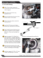
Dodge Charger
2006-2008 Stage II System
Installation Guide
®
The Intercooled Supercharging Experts!
®
© 2007 Accessible Technologies, Inc.
Accessible Technologies, Inc.
14801 W. 114th Terrace
Lenexa, KS 66215
Phone: 913.338.2886
Fax: 913.338.2879
[email protected]
All rights reserved. Accessible Technologies Inc. hereby grants permission to use and reproduce this
document for personal use, provided that all copyright information be retained. Reproduction of this
document for unauthorized commercial use is strictly prohibited.
Information in this document is subject to change without notice.
ProCharger is a registered trademark and The Intercooled Supercharging Experts!TM and Designed to
Blow Away the CompetitionTM are trademarks of Accessible Technologies, Inc. and may not be used
without express permission.
Revised 12/09
Part Number PMDD1A-001 Rev. F
Printed in the USA
Introduction
INTRODUCTION
Congratulations on purchasing your
ProCharger® Dodge Charger 2006-2007 Stage
II Intercooled System. Read this entire manual
before you attempt to install your ProCharger
kit. It is imperative that you follow all of the
instructions in the order they appear in this
installation guide. If you have any questions
regarding any aspect of this installation, call us
at (913) 338-3086.
For best results, we recommend reviewing
the installation instructions beforehand, and
following the installation instructions closely
and in sequence. A detailed packing list has
been provided (stapled to your invoice) to
assist you in identifying the components of
your ProCharger system.
Warning: Read and understand all
safety precautions in this manual
before installation. Failure to comply
with instructions in this manual could
result in personal injury, property
damage, and/or voiding your warranty.
Required Tools and Supplies
• 3/8” Socket Set (standard & metric)
• 1/2” Socket Set (standard & metric)
• 1/2” Breaker Bar
• Open End Wrench Set (standard & metric)
• 3/8” Hex Bit Set (allen head)
• Flat Screwdrivers
• Phillips Screwdrivers
• Plier Set
• 3-Jaw Gear Puller
• Loctite
You should also have the following gauges
available to properly check the finished
installation and monitor your vehicle’s
performance (especially for testing):
• Manifold Boost Pressure Gauge
• Fuel Pressure Gauge
• Wide Band Oxygen Sensor and Gauge
For complete system installations, please review the fuel system
and tuning section to ensure you have the proper components to
complete the installation. Tuning for this vehicle is a multi step
process that can be initialized before the installation has begun.
If there are any questions about this process, or any other step
during your installation, please call Procharger Technical Service
at 913-338-2886.
Dodge Charger 2006-2008 System Installation Guide
i
Introduction
Thank you and congratulations on the purchase of your ProCharger centrifugal supercharger system, and
welcome to the world of intercooled supercharging. You are now the owner of the most powerful, reliable,
and technologically advanced supercharger system available! With your new intercooled supercharger
system installed, you will experience horsepower gains in excess of 50% over stock!
If you are performing the installation of this system and this is your first supercharger installation, you
will likely benefit from reading the entire installation instructions prior to proceeding, and then reviewing
each section as you go. If you are familiar with supercharging, remember that intercooled supercharging is
different from non-intercooled supercharging, and the same rules do not necessarily apply. This is primarily
due to the unparalleled airflow and boost generated by the ProCharger, and the substantially cooler intake
temperatures that result from intercooling this boost.
Once your system is installed and dialed in, you will experience a performance gain that is much greater
than that delivered by non-intercooled supercharger systems. The utilization of intercooling technology
allows power gains for multiple reasons, primarily the following three:
1) Increased charge air density (lb/cubic ft) over non-intercooled applications. Cooler air is more dense, and
as such may be more easily delivered to the cylinders.
2) Decreased charge air temperature allows total spark advance closer to that which is ideal for peak power
production when compared to non-intercooled installations at similar boost levels.
3) The use of an intercooler allows higher peak boost levels for a given fuel (e.g.: pump gas). This means
charge air densities double that of atmospheric may be utilized on some pump gas applications,
resulting in power output nearly double that obtained when operating naturally aspirated.
ii
Dodge Charger 2006-2008 System Installation Guide
Introduction
TORQUE
SPECIFICATION
CHART
Thread Size
GRADE 5
GRADE 8
Torque (lb.ft.)
Torque (lb.ft.)
8
7
16
12
10
1/4-28
13
10
8
18
14
11
5/16-18
23
17
14
33
25
20
5/16-24
26
19
15
36
27
22
3/8-16
41
31
25
58
44
35
3/8-24
47
35
28
66
49
39
7/16-14
66
49
40
93
70
56
1/2-13
101
75
60
142
106
85
1/2-20
113
85
68
160
120
96
TECH TIP
11
ONE HEAT RANGE COOLER SPARK PLUGS ARE RECOMMENDED FOR USE WITH THIS
SYSTEM. WE SUGGEST REPLACING YOUR FACTORY PLUGS AT THIS TIME (CHAMPION
SPARK PLUG #RE14MCC4), GAPPED AT .035”.
TECH TIP
1/4-20
YOUR SUPERCHARGED VEHICLE MUST ALWAYS RUN ON 91 OCTANE OR BETTER GAS.
DO NOT RUN VEHICLE AT WIDE-OPEN THROTTLE IF YOU HAVE LESS THAN 1/4 TANK OF
GAS.
Dodge Charger 2006-2008 System Installation Guide
iii
Table of Contents
TABLE OF CONTENTS
Introduction .................................................................................................................................. i
Stock Component Removal.......................................................................................................... 1
Intercooler ................................................................................................................................... 4
Supercharger Crank Pulley ........................................................................................................... 8
Supercharger Bracket ................................................................................................................ 15
ProCharger Head Unit ............................................................................................................... 21
ProCharger Cog Belt.................................................................................................................. 23
Serpentine Belt .......................................................................................................................... 24
Tubing and Hoses....................................................................................................................... 25
Power Steering Components ..................................................................................................... 27
Vacuum Line ............................................................................................................................... 28
IAT Sensor .................................................................................................................................. 29
Fuel System ............................................................................................................................... 30
Tuning ........................................................................................................................................ 37
Engine Intake ............................................................................................................................. 39
Finishing..................................................................................................................................... 40
Operation and Maintenance ...................................................................................................... 41
Limited Warranty ....................................................................................................................... 43
ProCharger Extended Coverage ................................................................................................ 44
iv
Dodge Charger 2006-2008 System Installation Guide
Stock Component Removal
STOCK COMPONENT REMOVAL
Engine Air Filter
1
Disconnect the battery ground.
2
Remove the Engine cover(s).
3
Remove the Engine Air Filter Assembly
Bolts with a 10 mm socket.
4 Remove the PCV Tube from the intake
manifold.
Engine Air Filter Removed
5
Remove the IAT (Intake Air Temperature)
Sensor.
6
Remove the band clamp from the Air Filter
housing.
7
Remove the entire Air Filter Assembly.
Dodge Charger 2006-2008 System Installation Guide
1
Stock Component Removal
Front Grill
1
Remove the radiator cavity covers by
pulling up on the pieces until unsnap.
2
Remove the body fasteners from the
radiator internal side fairings that are
behind the front fascia.
3 Remove the radiator internal side fairings
from the radiator cavity.
Radiator Cavity Covers Removed
4
Remove the four phillips head screws from
front grill by reaching behind the front
fascia from top.
5
Pull on the grill while releasing the four
tabs and remove the grill.
Front Grill Removed
2
Dodge Charger 2006-2008 System Installation Guide
Stock Component Removal
Underside Body Cladding
1
Raise the vehicle.
2
Remove the six panel fasteners, three in
each front fender well, with a flat head
screwdriver.
3 Remove four 10 mm bolts and remove the
back cladding.
4
Remove ten 7 mm bolts and remove front
cladding.
Underside Body Cladding
Underside Body Cladding Removed
Dodge Charger 2006-2008 System Installation Guide
3
Intercooler
INTERCOOLER
1
Remove the power steering cooler from
the condenser by placing the appropriate
tool behind the bracket and prying off. Do
not damage the condenser core.
Power Steering Cooler Removal Tool
Power Steering Cooler Detached
2
Remove the horns and brackets with a
10 mm socket.
3 Disconnect the hose from the driver’s side
of the power steering cooler and re-route
it under the frame rail. Reconnect the
hose.
4
4
Temporarily pull the cooler behind the
radiator to provide working space for the
intercooler.
Horn Locations
Dodge Charger 2006-2008 System Installation Guide
Intercooler
5
Remove the metal tab on the driver’s side
of the condenser. Bend back and forth
until it breaks off.
6
Temporarily remove the outside air
temperature sensor for easier installation
of the intercooler.
Condenser’s Metal Tab Removal
7 Assemble the intercooler brackets as
shown using thread locker.
Intercooler Brackets
Dodge Charger 2006-2008 System Installation Guide
5
Intercooler
8
Remove the frame bolt with a 13 mm
socket.
Frame
Bolt
Frame Bolt
9
Install the intercooler brackets as shown
using the supplied hardware.
Tech Tip: If installing this system onto
a 6.1L SRT8 vehicle, install the supplied
3/8” washers behind each intercooler
bracket for proper spacing.
Driver’s Side
Intercooler Bracket Installed
10 Rotate the horn mounting positions on
brackets. The horn exit needs to be
perpendicular to the bracket’s mounting
surface as shown.
Original Horn Configuration
New Horn Configuration
6
Dodge Charger 2006-2008 System Installation Guide
Intercooler
11 The passenger’s side horn now mounts on
the driver’s side and vise versa. Mount as
shown using the supplied black locking
flange nut.
Horn Reinstalled
12 Route the horn wire extension below the
intercooler and behind the front bumper
from the passenger’s side to the driver’s
side. You may tuck the wire between the
bumper and bumper cladding.
13 Pull the intercooler out away from the
condensor as far as possible. Also, be sure
the intercooler is also pushed down as low
as possible, this will allow proper clearance
for the radiator covers which will be
reinstalled later. Tighten the intercooler
with the supplied bolts.
Intercooler Installed
14 Reinstall the outside air temperature
sensor.
Dodge Charger 2006-2008 System Installation Guide
7
Supercharger Crank Pulley
SUPERCHARGER CRANK PULLEY
Fan Assembly Removal
Tech Tip: You must remove the fan
and shroud assembly to install the
crank pulley.
1
Disconnect the main electrical
connection located on the top left of
fan housing.
2
With a 10 mm socket, remove the top
two bolts in the corners.
Main
Electrical
Connection
10 mm
Bolts
Engine Fan
3 With a 10 mm socket, remove the
retaining screw from the clamp of the
power steering line to frame to provide
clearance for the fan assembly removal.
4
Lift the fan up past the hooks and drop
the assembly to the floor and remove.
5
With a 10 mm socket, remove the
transmission access cover to access the
starter ring gear.
6
Lock up the transmission using
appropriate tool.
7 Remove the bolt from the center of the
damper pulley with a 21 mm socket.
8
Dodge Charger 2006-2008 System Installation Guide
Supercharger Crank Pulley
Radiator Removal
Tech Tip: You must remove the
radiator for clearance to install the ATI
Performance Products Damper on 6.1L
vehicles.
1
Remove the coolant reservoir cap. Drain
the radiator by opening the drain cock
located on the bottom passenger side of
the radiator.
2
Disconnect the upper and lower radiator
hoses from the radiator.
3
Remove the (4) 13mm bolts securing
the radiator core support to the vehicle.
Remove the core support.
4
Remove the (4) 10mm bolts holding
condensor to the radiator.
5
Carefully remove the radiator from the
vehicle, allowing the ac condensor to
remain in teh vehicle. It may be best to zip
tie the condensor to the vehicle, out of the
way.
Radiator Core Support Bolts (Pass. Side)
Dodge Charger 2006-2008 System Installation Guide
9
Supercharger Crank Pulley
5.7L Crank Pinning
7$3(
0;%2/7
M14-1.50
x 120MM BOLT
Tech Tip: If installing this system onto a
6.1L SRT8 vehicle, an ATI Performance
Products Super Damper part #918432
(optional on the 5.7L uses ATI Performance
Products Super Damper part #918435) is
required and must be purchased separately.
1
With a 10 mm socket, remove the
transmission access cover to access the
starter ring gear.
2
Lock up the transmission using
appropriate tool.
'5,//-,*
&5$1.3,11,1*),;785(
0',
CRANKSHAFT AND HARMONIC BALANCER DRILL JIG
3 Remove the bolt from the center of the
balancer with a 21 mm socket.
4
Place the drill jig onto the crank pulley,
tighten it into place using the supplied
M14-1.50 x 120mm hex head bolt.
5 Tape the supplied 1/4” HSS drill bit
1-5/8” from the tip. Using this taped drill,
drill a hole in the crankshaft and harmonic
balancer stopping at the tape edge of the
drill. The hole will be centered on the OD
of the crankshaft. Do not drill deeper than
.800” into the face of the crankshaft.
6
Remove the pinning tool and set aside.
Clean the chips from inside the drilled hole
and the surrounding area throroughly.
7
Install the supplied 1/4” OD x .75” long
stainless steel dowel pin in the hole.
DRILL JIG INSTALLED
DRILLING THE CRANK
10
Dodge Charger 2006-2008 System Installation Guide
Supercharger Crank Pulley
5.7L Crank Pinning (Cont.)
8
Install the supercharger crank pulley over
the stock balancer and turn it counter
clockwise until the crank pins stop against
the balancer spokes.
Warning: Viewing the engine from front,
the crank damper rotates clockwise. The
crank pulley must be rotated counterclockwise until the crank pins stop
against the damper spokes before bolt
is tightened. If this is not performed,
permanent damage to the vehicle could
occur!
9
CRANK PULLEY PINNED TO CRANKSHAFT
Using the original bolt, torque the
balancer bolt to 129 ft-lbs.
Supercharger Crank Pulley Installed
Dodge Charger 2006-2008 System Installation Guide
11
Supercharger Crank Pulley
6.1L Crank Pinning
1
With a 10 mm socket, remove the
transmission access cover to access the
starter ring gear.
2
Lock up the transmission using
appropriate tool.
3 Remove the bolt from the center of the
balancer with a 21 mm socket.
REMOVING THE FACTORY BALANCER
4
5
7$3(
Using a 3-jaw gear puller, remove the
factory balancer.
0;%2/7
M14-1.50
x 120MM BOLT
Install the ATI Performance Products
balancer per manufacturers instructions.
'5,//-,*
&5$1.3,11,1*),;785(
0',
6
Place the drill jig onto the balancer hub,
tighten it into place using the supplied
M14-1.50 x 120mm hex head bolt and
washer.
7 Tape the supplied 1/4” HSS drill bit 1
5/8” from the tip. Using this taped drill,
drill a hole in the crankshaft and harmonic
balancer hub stopping at the tape edge of
the drill. The hole will be centered on the
OD of the crankshaft. Do not drill deeper
than .800” into the face of the crankshaft.
8
Remove the pinning tool and set aside.
Clean the chips from inside the drilled hole
and the surrounding area throroughly.
9
Install the supplied 1/4” OD x .75” long
stainless steel dowel pin in the hole.
12
CRANKSHAFT AND HARMONIC BALANCER DRILL JIG
DRILL JIG INSTALLED/DRILLING THE CRANK
Dodge Charger 2006-2008 System Installation Guide
Supercharger Crank Pulley
6.1L Crank Pinning (Cont.)
10 Using the original bolt, torque the
balancer bolt to 129 ft-lb.
11 Attach the supplied supercharger drive
crank pulley to the ATI Performance
Products balancer using the supplied (3)
3/8-16 x 1 1/2” HHCS.
CRANK PULLEY INSTALLED
Dodge Charger 2006-2008 System Installation Guide
13
Supercharger Crank Pulley
Re-Installing Components
1
Install the transmission access cover.
2
Reinstall the radiator and radiator cradle.
3
Zip tie the A/C lines down out of the way.
4
Reinstall the factory 6 rib accessory belt
(if installing onto a 6.1L vehicle, use the
supplied belt.)
AC Lines Zip Tied Out of Way
5 Reinstall the fan.
Tech Tip: If installing the system into a
6.1L SRT8 vehicle, the fan and shroud must
be reconfigured. Before reinstalling the
fan, rotate the passenger side fan motor
so the plug is on the opposite side, this
provides additional belt clearance. Also,
some clearancing of the drivers side
fan shroud might be required for belt
clearance. This can be accomplished by
sanding or grinding the fan shroud as
needed.
TRIM
Reconfigured 6.1L Fan
6
Reinstall fan bolts and reconnect the
electrical connection.
7
Adjust the power steering line by
unbolting the clamp holding the power
steering line. Slide the line towards the
driver’s side as far as possible and tighten
clamp. Do not disconnect the line.
Power Steering Line’s New Position
14
Dodge Charger 2006-2008 System Installation Guide
Supercharger Bracket
SUPERCHARGER BRACKET
Power Steering Hose
1
With a 18 mm wrench, loosen the power
steering pressure side hose. Rotate hose
as shown.
2
Remove the SHCS with a 5 mm hex bit
socket from the power steering return
hose. Rotate the power steering line and
install the retaining bracket (3DDPS-001)
as shown with a 13 mm socket.
Power Steering Hose’s Original Position
Power Steering Hose’s New Position
Power Steering Return Hose’s
New Position with Retaining Bracket
Dodge Charger 2006-2008 System Installation Guide
15
Supercharger Bracket
Driver’s Side Brake ABS Sensor
1
Unplug and remove the connection from
fender by pressing down on the wire clip
and gently pulling on the plug.
ABS Sensor Connector Fender Side
2
Remove the tabs from female connection.
Tabs
ABS Sensor Connector with Tabs
ABS Sensor Connector without Tabs
16
Dodge Charger 2006-2008 System Installation Guide
Supercharger Bracket
3
Zip-tie the connector back into the hole
from the tire side so the secondary flange
engages the fender on the inside of the
engine compartment.
ABS Sensor Connector Zip Tied
4
Zip-tie the harness down to the brake lines
as shown.
Zip Tie
ABS Sensor Zip Tied to Brake Line
Dodge Charger 2006-2008 System Installation Guide
17
Supercharger Bracket
Tensioner and Belt
1
Remove the serpentine belt.
2
Remove the factory automatic belt
tensioner using a 15 mm socket.
13 mm
Bolt
3 Remove the front cover bolts with a
13 mm and a 15 mm socket.
15 mm
Bolt
Supercharger Bracket Bolts
4
5
6
7
Lower
Bracket
Install the lower sub-bracket, as shown,
using a 6 mm hex bit socket.
Upper
Bracket
Install the upper bracket, as shown,
using 8 mm hex bit socket.
M10 x
45 mm
Align brackets and tighten SHCS.
M8 x
130 mm
M8 x
120 mm
Reinstall the factory tensioner.
M8 x
100 mm
8
Reinstall the serpentine belt, verify the
belt is correctly aligned on each pulley.
9
Install the idler pulley and idler shaft onto
the upper bracket with a 9⁄16” socket.
Upper and Lower Brackets Installed
⁄16” Bolt
9
Idler Pulley
18
Dodge Charger 2006-2008 System Installation Guide
Supercharger Bracket
Lower Bracket
1
Raise the vehicle in order to access the
A/C compressor.
2
Remove two air conditioner compressor
bolts from the front of the unit using a
15 mm socket.
3 Install the lower bracket as shown using
the two M10 SHCS with an 8 mm hex bit
socket. Tighten to 37 ft-lb (50 N-m).
Lower Bracket Installed
Dodge Charger 2006-2008 System Installation Guide
19
Supercharger Bracket
Main Bracket
1
Verify the three drive transfer bolts on the
back of the main bracket are loose. You
will tighten the drive transfer bolts after
the cog belt is installed.
2
Lower the main bracket assembly into the 0.65”
Spacer
location as shown.
3 From the bottom of the car, insert the
bottom 5⁄16 - 18 x 4.0” SHCS with the 1.72”
spacer using a 1⁄4” hex bit socket. Do not
tighten.
4
From above the car, insert the top back
M8 - 1.25 x 40 mm SHCS with the 0.65”
long spacer using a 6 mm hex bit socket.
Do not tighten.
5
With a 6 mm hex bit socket, insert the top
front M8 - 1.25 x 30 mm SHCS. Align the
brackets and tighten all bolts.
0.72”
Spacer
Main Bracket Installed
Drive Transfer Bolts
Tech Tip: The lower drive transfer bolt
may be removed to make the cog belt
adjustment easier. Use thread locker
when reinstalling the cog pulley!
6 To provide clearance for the ProCharger
head unit, rotate the power steering
reservoir clamps as shown.
Rotate
Clamp
Rubber
U-Channel
Rubber U-Channel Installed
20
Dodge Charger 2006-2008 System Installation Guide
ProCharger Head Unit
PROCHARGER HEAD UNIT
1
Install the PCV Hose onto the drivers side
valve cover bung and route to the front
of the vehicle. Secure it in a position that
aims straight down at the ground. Use
the supplied zip ties to secure the line out
of the way of moving components (belts/
pulleys/etc.)
Tech Tip: The PCV line can be attached
to a catch can (not included) for oil
collection.
Main Bracket
2 Before installing the supercharger, attach
the 45º hose, slightly rotated using a #52
band clamp onto the supercharger as
shown. Remove the outer flange from
the supercharger cog pulley to make belt
installation easier.
ProCharger Head Unit
Dodge Charger 2006-2008 System Installation Guide
21
ProCharger Head Unit
3
Fit the supercharger into the bracket.
4
With the two 3⁄8-16 x 1¼” SHCS start
mounting the supercharger onto the
bracket. Thread in remaining 5⁄16-18 x ¾”
SHCS. Tighten all SHCS.
5
Install the supplied intake bellmouth
assembly onto the inlet of the
supercharger. Secure the connection with
the supplied #60 hose clamp.
ProCharger Head Unit Installed
22
Dodge Charger 2006-2008 System Installation Guide
ProCharger Cog Belt
PROCHARGER COG BELT
1
Position the lower cog pulley in the loose
position by rotating the drive transfer
housing counter-clockwise.
2
Remove the outer flange from the
ProCharger cog pulley.
3 Feed the cog belt onto the lower cog
pulley.
4
Roll the cog belt onto the upper cog
pulley.
5
Reinstall the flange to the upper cog
pulley using Loctite on each of the screws.
6
To tighten the cog belt, rotate the drive
transfer housing clockwise and align the
first marks on housing and bracket. After
approximately 1,000 miles, re-tension the
cog belt by rotating the drive transfer
housing to second mark.
7
Tighten the three 1⁄4-20 x 5⁄8” bolts located
on the back bracket to lock in the drive
transfer housing with a 7⁄16 wrench.
8
Cog Pulley Outer Flange
Cog Pulley Guard
Install the cog guard.
Dodge Charger 2006-2008 System Installation Guide
23
Serpentine Belt
SERPENTINE BELT
1
2
Make sure the adjustable idler pulley
is in the lower location and install the
serpentine belt as shown below.
Adjustment
Screw
Tension the serpentine belt by adjusting
the idler pulley adjustment screw.
3 Using a ¾” wrench, tighten the brass nut
at the front of the pulley to lock the idler
pulley in place.
Serpentine Belt Adjustment Pulley
Serpentine Belt Path
24
Dodge Charger 2006-2008 System Installation Guide
Tubing & Hoses
TUBING AND HOSES
Intercooler Tubing
Warning: Inspect the inside of each
tube for any foreign debris. Remove
any debris from the interior of the tubes
before installing.
Tech Tip: Drivers side brake cooling
duct needs to be removed or trimmed
for intercooler tubing clearance.
Intercooler Tubing
1
Install tube AIDDI1-007.
2
Install tube AIDDI1-006. Install hose as
shown to insulate against the A/C line.
Contact
Area
A/C Line and Tube AIDDI1-006
Dodge Charger 2006-2008 System Installation Guide
25
Tubing & Hoses
ProFlow
1
Route the vacuum line from the top of the
engine bay. Do not connect at this time.
2
Trim the elbow hose to the minimum
length and install on to the ProFlow.
3 Plug the vacuum line onto the ProFlow.
4
26
Mount the ProFlow on the tube as shown.
ProFlow Installed
Dodge Charger 2006-2008 System Installation Guide
Power Steering Components
POWER STEERING COMPONENTS
1
Remove the plastic retainers from the
power steering cooler ends.
2
Clip the bosses.
3 Drill the pilot holes into the bottom of the
plastic retainer using a 3⁄16” bit.
4
Reinstall the plastic retainer onto the
power steering cooler.
5
Mount the bracket to the power steering
cooler using the supplied phillips head
screws.
6
Bend the tabs on the radiator support.
7
Loosen the clamp and rotate the cooler.
8
Install the bracket for the power
steering cooler on the two tabs located
at bottom of the condenser.
Power Steering Cooler
Plastic Retainer Clips
Supplied
Screws
Tech Tip: If installing onto a 6.1L SRT8
vehicle, the power steering bracket
must be spaced out using the supplied 4”
tube spacers and supplied longer bolts.
9
Power Steering Cooler
Stabilize the power steering line by
mounting the bracket as shown.
Power Steering Line
Dodge Charger 2006-2008 System Installation Guide
27
Vacuum Line
VACUUM LINE
1
Assemble the supplied vacuum manifold
as shown. If you have or are installing a
boost gage, do not install the plug, use an
additional barb fitting. Thread each fitting
into the manifold. Thread the 3/8” barbed
fittings onto each end of the manifold.
(The boost switch is used for full system
6.1L SRT8 models only. If you are installing
this kit onto a 5.7L model, plug this port.)
2
Locate the brake booster hose located on
the drivers side near the firewall. Remove
a 3 1/2” section of this hose in order to
place the manifold in line.
3
Mount the manifold by sliding each barbed
fitting into the open ends of the brake
booster hose. Secure the connection with
the provided #06 hose clamps.
4
Be sure the brake booster hose
connections are tight, verify the
connection to the booster did not come
loose as well.
5
Route a vacuum line from the vacuum
manifold and attach it to the barb located
on the Proflow surge valve. Secure the
line with provided zip ties.
28
Plug
Manifold
Boost Switch
Line to Surge Valve
Vaccum Manifold Assembly
Vacuum Manifold Installed
Dodge Charger 2006-2008 System Installation Guide
IAT Sensor
IAT SENSOR
1
Tape back the IAT (Inlet Air Temperature)
sensor’s braided sleeve with electrical
tape.
2
Cut off the IAT sensor and strip ~¼” of
insulation from the wires.
3 Slide heat shrink over wires.
4
Connect the blue with green stripe wire to
#1 and the blue wire to #2 plug positions.
IAT Sensor Modification
5
Solder the new IAT sensor to the wires.
6
Insulate the solder joints with heat shrink
and replace braided sleeve.
Dodge Charger 2006-2008 System Installation Guide
29
Fuel System
FUEL SYSTEM
(FULL SYSTEMS ONLY)
Fuel Injectors
1
Reconnect the battery.
2
Remove relay 46 from the panel in the
trunk.
3
Crank the engine for 15 seconds.
4
Disconnect the battery.
5
Unclip the wiring harnesses from each
injector. Remove the four 10mm bolts
securing the fuel rails to the manifold. Pull
the fuel rails up off of the manifold to gain
access to the fuel injectors.
6
Relay 46
Remove the fuel injector retaining clips
from the injectors and rails. Remove the
injectors by pulling them straight out of
the rails.
Electrical Panel
Rail Spacer
Tech Tip: Lightly oiling the injector
o-rings eases installation.
7
Install the new injectors, followed by the
factory retaining clips.
8
Due to injector height, spacers must be
used to space the rail correctly. Mount the
spacers on the manifold, push the injector
and rail assembly into place, and tighten
the rails with the new hardware. Reinstall
each wiring harness to each injector.
30
Fuel Rails Installed
Dodge Charger 2006-2008 System Installation Guide
Fuel System
Map Sensor (6.1L SRT8 Models)
1
Remove the factory MAP sensor located
on the backside of the intake manifold.
Remove the electrical harness by
sliding the red retaining tab back and
disconnecting it from the sensor. Remove
the two 8mm bolts and pull the factory
MAP sensor out of the vehicle.
2
Install the new 2 bar MAP sensor
(05033224AB), tighten the 8mm bolts, and
connect the harness to the new sensor.
2 Bar MAP Sensor Installed (6.1L SRT8 Model)
Map Sensor (5.7L Models)
1
Remove the factory MAP sensor located
on the backside of the intake manifold.
Remove the electrical harness by sliding
the red retaining harness tab back and
disconnecting it from the sensor. Remove
the two 8mm bolts and pull the factory
MAP sensor out of the vehicle.
2
Install the supplied o-ring onto the MAP
adaptor. Install the MAP adaptor onto the
manifold, followed by the supplied 2 bar
MAP sensor (05033224AB). Reinstall the
8mm bolts, and plug in the harness.
Dodge Charger 2006-2008 System Installation Guide
2 Bar MAP Sensor Installed (5.7L Model)
31
Fuel System
Fuel Pump Booster
(Booster is only included and
required for 6.1L SRT8 Models
Only)
1
Make sure the ignition is off and the key is
removed from the ignition.
2
Connect the manifold pressure trigger
wiring to the boost switch and insulate the
terminals using the supplied shrink tubing
(Figure 1).
3
Connect the boost switch to the vacuum
manifold if not already done (Figure 2).
4
Route the trigger wiring to the power
distribution center located in the trunk
(Figure 3-8).
Boost Switch (Figure 1)
Vacuum Manifold (Figure 2)
32
Dodge Charger 2006-2008 System Installation Guide
Fuel System
Fuel Pump Booster
Firewall Penetration (Figure 3)
Wires in Glovebox (Figure 4)
Wires in Door Sill (Figure 5)
Dodge Charger 2006-2008 System Installation Guide
Wires Through Backseat (Figure 6)
Wires into Trunk (Figure 7)
Wires to Power Disctibution Module
(Figure 8)
33
Fuel System
Fuel Pump Booster
5
In the trunk of the vehicle, remove the fuel
pump fuse from the Power Distribution
Center (Figure 9).
6
Peel back the protective sheath from the
wire bundle several inches (see Figure 10),
locate and cut the power to the fuel pump,
dark blue with orange stripe wire. Prior to
cutting, confirm the wire color at the fuel
pump module.
Fuel Pump Power Wire (Figure 10)
Tech Tip: Prior to cutting, confirm the
wire color at the fuel pump module.
Remove the back seat, remove the fuel
pump module cover (Figure 11), unplug
the fuel pump wiring connector, and
verify the wire in position number 5 is
dark blue with an orange stripe (Figure
12).
Fuel Pump Module Cover(Figure 11)
Fuse
Fuel Pump Fuse (Figure 9)
Fuel Pump Wiring Connector(Figure 12)
34
Dodge Charger 2006-2008 System Installation Guide
Fuel System
Fuel Pump Booster
Wiring Diagram(Figure 13)
Dodge Charger 2006-2008 System Installation Guide
35
Fuel System
Fuel Pump Booster
7
Connect the Flowcharger wiring as shown
in the wiring schematic (Figure 13). Be
sure the FLowcharger has a solid ground
contact.
8
Securely mount the Flowcharger. For
high power or high ambient tempertaure
useage, Flowchargers should be mounted
outside of the spare tire well where it is
exposed to cooling air. Wires must be cut
long enough to allow proper mounting.
Fuel Pump Module Cover(Figure 14)
Flowcharger Mounted In Wheel Well
(Figure 15)
36
Dodge Charger 2006-2008 System Installation Guide
Fuel System
Predator Flash Tuning
Hardware and Software Requirements:
1. DS Downloader version 1.9.9.6
http://www.diablosport.com/index.php?module=htmlpages&func=display&pid=1
21
2. PC or Laptop with internet connection and 9-pin serial port or USB port
A serial cable and an AC to DC power adapter must be obtained. DiabloSport offers both of these
items in a package that can be purchased through any authorized DiabloSport dealer. The part number
for this item is U7777. Alternatively, these items can be purchased locally from any Radio Shack or
similar electronics retailer. The descriptions, part numbers and recommended source for these items
are presented below.
1) Serial Cable:
- For PC’s with DB-9 serial communications port(s):
A standard, RS-232C, straight through, DB-9 male to DB-9 female cable is required to connect the
PC to the Predator.
Recommended Source: Radio Shack part number: 26-117, 6-ft DB9 male to DB9 female shielded
RS-232C cable
- For PC’s with USB ports only:
If the PC only has USB ports available, a USB to RS-232C converter cable is required. This cable
will convert a USB port to a serial port to connect to the Predator.
Recommended Source: Radio Shack part number: 26-183, 6-ft USB to Serial Port Adapter Cable
2) Power Adapter:
The Predator requires a 12 Volt, 1 Amp power source to turn it on. An AC to DC power adapter
allows the Predator to be turned on when not connected to the vehicle. The Power Adapter’s plug
tip is 2.5mm in diameter and 5.5mm in length. The required polarity is center contact is positive
and the outer contact is ground.
Recommended Source: Radio Shack part number: 273-1776, 12V/1000mA AC to DC Power
Adapter (This item includes a Plug Adapter. Please specify part number: 273-1717 to obtain the
correct adapter.
* Note: If the update will be performed with a laptop computer, the vehicle’s OBDII port can be
used to substitute for the Power Adapter.
Dodge Charger 2006-2008 System Installation Guide
37
Fuel System
Predator Flash Tuning
1
Peform the “Calibration Update” using the
supplied Predator U7135 Predator. Plug
the Predator into the vehicle’s OBDII port.
Proceed to perforamance tune and follow
the on screen prompts. If no calibration
update is prompted, proceed to step 2.
2
Install the performance tune, modify stock
tune from Predator ECM.
1) Select performance tune.
2) Select Diablo tunes.
3) Select modify stock tune.
3
Unplug the handheld from the vehicle.
4
Using DS Downloader, download the
original file from the Predator to a PC, and
email the tune to [email protected]
along with the Procharger serial number in
the subject line.
5
[email protected] will email back
the tune for your vehicle. Upload the tune
from your PC to the Predator using DS
Downloader.
6
Load the Procharger tune from the
Predator to the ECM
1) Select Performance Tune
2) Select Custom Tune
3) Select Tune and follow on screen
prompts.
38
Dodge Charger 2006-2008 System Installation Guide
Engine Intake
ENGINE INTAKE
1
Disconnect the ABS wiring harness
from the ABS module located by the
passenger’s side fender.
2
Slide the molded hose into position and
mount to intercooler’s coupler using a #52
band clamp. The clamp can be tightened
from the top.
Tech Tip: Shape second #56 band clamp
into oval before sliding onto molded
hose.
Intercooler Hose Installed
3 Install the molded plastic intake by first
inserting into molded hose. Use tire shine
on mating components to make assembly
easier.
4
Connect the engine intake with a 3¾”
rubber hose and secure with two #56 band
clamps.
5
Install the supplied sensor and connect the
wire harness.
6
Reconnect the ABS wiring harness. The
Sensor
ABS block is mounted on the rubber
grommets, it may be necessary to flex the
ABS block out to provide clearance.
Intake Tube
ABS Wiring Harness
Dodge Charger 2006-2008 System Installation Guide
39
Finishing
FINISHING
1
Cut the engine cover as shown (5.7L
engine cover only, 6.1L SRT8 covers do not
need to be trimmed.)
2
Reinstall the engine cover(s).
3 Reinstall the front grill.
4
Reinstall the underside cladding.
5
Clear system of any installation debris.
6
Reconnect the battery.
Engine Cover
40
Dodge Charger 2006-2008 System Installation Guide
Operation and Maintenance
OPERATION AND MAINTENANCE
Cold Starting
Belt Replacement
Never race your engine and ProCharger
supercharger when your engine is cold. Allow
the water temperature to climb into operating
range for several minutes before driving above
2,500 rpm, to ensure adequate oil lubrication.
The serpentine belt, which turns your ProCharger
supercharger, will stretch after initial run-in, and
should be retightened after the first hundred
miles. Tighten the belt sufficiently to avoid
slippage, but do not overtighten. Overtightening
the belt could cause damage to the ProCharger
supercharger’s precision bearings. When
reinstalling the belt, use the belt routing diagram
in this manual. If you reuse a thrown belt and
find that it needs frequent re-tightening, the
belt is damaged and should be replaced. Gates
Micro-V belts can be bought from ATI or from
your local parts store.
Fuel Quality
With a properly installed intercooled ProCharger
supercharger system, detonation should not
occur. For the best performance and reliability,
use premium grade fuel (91 octane or higher).
Listen for signs of detonation after refueling,
and after replacement or modification of any
fuel system component(s). If detonation occurs,
reduce the throttle and locate the source.
Ignition System Maintenance
If your spark plugs are more than a year old or
have more than 10,000 miles logged, you should
consider changing them before driving your
vehicle under load. Spark plug wires should be
changed if visibly damaged or when resistance
exceeds factory specifications.
ProCharger Oil Change Intervals
The first oil change should be performed at 500
miles and at 6,000 mile intervals thereafter. Clean
drain plug after every oil change. Drain oil by
removing the drain plug. Clean off drain plug
before reinstalling.
Air Filter Maintenance
Your air filters should be cleaned periodically,
potentially as often as every 10,000 miles
or 6 months, even though a service interval
of 50,000 - 100,000 miles is quoted by the
manufacturer under normal driving conditions.
A clogged air filter will result in decreased boost
levels and vehicle performance. Be sure to reoil the cleaned filter before re-installing. Always
operate your vehicle with an air filter, failure to
do so may result in damage to your ProCharger
supercharger and personal injury!
Dodge Charger 2006-2008 System Installation Guide
41
Operation and Maintenance
ProCharger Oil Level
General
The ProCharger supercharger’s oil level must
be checked periodically to ensure the proper
lubrication. The dipstick can be loosened
using a flat blade screwdriver or a coin. When
installed, the oil level should remain between the
minimum (MIN) and maximum (MAX) indicators
at all times.
When removing the warning tag from the
dipstick, be sure to retain the nylon washer. A
spare nylon washer and o-ring is included. Use
only the ATI supplied nylon washer and o-ring
when servicing the oil dipstick and drain plug. A
discoloration of the oil and residue on the drain
plug may occur during the initial oil changes.
This is normal and will gradually decrease.
For the proper positioning of the ProCharger
supercharger, the serial tag should be pointing
upwards. Installing the ProCharger supercharger
in another position will cause inadequate
oiling and supercharger failure. If you have
any questions about the maintenance of your
supercharger, contact ATI.
Warning: Filling the ProCharger higher
than the maximum level on the dipstick
can lead to bearing and seal damage.
The supercharger is a sealed unit and
should not normally require the addition
of oil between service intervals. If
excessive usage is noted, the unit should
be sent to ATI for inspection and repair.
The dipstick fitting should be firmly
tightened after changing or checking the
oil level.
Sealed Plug
(socket head)
Magnetic
Drain Plug
(hex head)
Sealed Plug
(socket head)
Dipstick
(flat head)
42
Dodge Charger 2006-2008 System Installation Guide
Limited Warranty
LIMITED WARRANTY
Accessible Technologies, Inc. (ATI) provides a limited
twelve (12) month warranty on the ProCharger
supercharger against defects in materials and
workmanship unless otherwise specified. This limited
warranty starts on the date of original purchase from
your local dealer, or date of shipment from the factory.
This limited warranty coverage is extended only to the
original owner and excludes hoses, sleeves, and electronic
components manufactured by other companies. IF THE
SUPERCHARGER’S DRIVE RATIO IS ALTERED IN ANY WAY
FROM THE FACTORY SETTING, WARRANTY COVERAGE
IS VOID. USE OF ANY PULLEY NOT MANUFACTURED OR
SUPPLIED BY ATI VOIDS ALL WARRANTY COVERAGE.
ATI’s warranty obligations are limited to the terms below:
ATI agrees to honor a warranty claim at its sole discretion
and only after inspection at the ATI factory. No warranty
will be honored if any part of the product is found to have
been improperly installed, tampered with, mishandled,
or misused in any way. Disassembly of the ProCharger
supercharger or removal of the ProCharger supercharger’s
serial plate voids all warranties. Claims for freight damages
should be directed to the freight company.
If ATI’s limited warranty applies, your product will be
repaired or replaced at ATI’s discretion and shipped back.
If the limited warranty does not apply, ATI will advise you
of the specific reason, cost of the repair, and delivery
time. After advising you of this information we will, at your
option, either proceed with repairs or return your product
to you in the state in which it was received. In either
case the product will be shipped to you COD, insured
at replacement value. Therefore, you will pay the return
shipping and insurance charges if ATI’s limited warranty
does not apply to your product.
To obtain service under this warranty you must do the
following during the warranty period:
Phone ATI (913-338-3086) and provide us with the
following information:
- ProCharger supercharger serial number.
- Vehicle year, make, model, engine modifications, and
other modifications.
- Description of perceived issue.
If a solution to your issue can not be found after the
above phone consultation, you will be assigned a return
authorization number (RMA). Package the You must then
properly ship your product, at your expense, to the ATI
factory. The product should be carefully packaged in a
rugged box.
Include the following information inside the box with
your product:
- Copy of your original invoice or receipt.
- Name, address, and daytime telephone number.
- Return authorization number (RMA).
- Vehicle year, make, model, engine modifications, and
other modifications.
- Description of perceived issue.
Clearly mark the warranty claim number on the top and
one side of the box in characters at least 2” tall. Properly
package the product and ship it, prepaid and insured for
the retail value of the component(s) being returned, to the
following address:
Accessible Technologies, 14801 West 114th Terrace,
Lenexa, Kansas 66215
THE WARRANTY AND REMEDIES SET FORTH ABOVE
ARE EXCLUSIVE AND IN LIEU OF ALL OTHERS, ORAL
OR WRITTEN, EXPRESS OR IMPLIED. THE DURATION
OF ANY AND ALL WARRANTIES ON THE PRODUCTS
DISCUSSED ARE LIMITED TO THE PERIOD IDENTIFIED
ABOVE. ATI IS NOT RESPONSIBLE IN ANY EVENT FOR
DIRECT, SPECIAL, INCIDENTAL OR CONSEQUENTIAL
DAMAGES. No ATI dealer, agent, or employee is
authorized to make any modification, extension, or
addition to this warranty.
Dodge Charger 2006-2008 System Installation Guide
43
ProCharger Extended Coverage
PROCHARGER EXTENDED COVERAGE
The ProCharger Extended Coverage Program
extends the ProCharger warranty coverage for
your an additional twenty-four (24) months, for
a total of thirty-six (36) months or three years
of coverage. This extended coverage applies
to parts for the ProCharger supercharger head
unit only and does not include other system
components. With your extended coverage
registration, you will receive two (2) additional
boxes of ProCharger Supercharger oil.
•
- Disassembly or modification the
ProCharger supercharger.
- Removal or attempted removal of the
ProCharger drive pulley(s).
Under the extended coverage program,
Accessible Technologies, Inc. (ATI) will repair or
replace any component within the supercharger
head unit which is found to be defective. Only
the supercharger head unit itself is included in
the extended coverage.
Service under the extended coverage program is
obtained through the same process as described
in the Limited Warranty.
Race kits and tuner kits are not eligible for the
ProCharger Extended Coverage Plan
To qualify for the ProCharger Extended
Coverage:
•
Only the original owner of the ProCharger
supercharger is eligible.
•
Completion of the Extended Coverage
Registration Form is required, along with
a $49 registration fee. This form must be
completed in its entirety, and must be
submitted along with payment within 30 days
from the date of original purchase from your
local dealer or date of shipment from the
factory.
Participants must have a ProCharger P-1SC,
P-1SC-1, C1, or C2 supercharger head
unit using the maximum warranted boost
level. All terms and conditions within “The
Limited Warranty” apply. Acts resulting in
disqualification include but are not limited to
the following:
- Removal or attempted removal of
the ProCharger supercharger serial
number plate.
- Removal or attempted removal of the
compressor housing or transmission
case.
•
Participants agree to properly maintain
the ProCharger supercharger and provide
proof of compliance with the following
recommended maintenance:
- Change the ProCharger supercharger
oil after the initial break-in period of
500 miles (automotive) or 15 hours
(marine).
- Change the ProCharger supercharger
oil every 6,000 miles after the initial
break-in period.
- Use only the specified amount of
ProCharger Supercharger oil in the
ProCharger supercharger.
- Inspect and clean the magnetic
drain plug at every ProCharger
supercharger oil change.
- Check the ProCharger supercharger oil
level frequently.
44
Dodge Charger 2006-2008 System Installation Guide
ProCharger Extended Coverage
Dodge Charger 2006-2008 System Installation Guide
45
ProCharger Extended Coverage Program Registration Form
cut along the dotted line
Return this completed form and a $49 check within 30 days of original purchase.
Name:_________________________________
Date of Purchase:_______________________
Address:_______________________________
Purchased From:_______________________
City:___________________________________
ProCharger Serial #:_____________________
State:________________
Zip:____________
Vehicle Year:___________________________
Daytime phone:_________________________
Vehicle Make:__________________________
Evening phone:_________________________
Vehicle Model:_________________________
E-mail:_________________________________
Please rank in order of importance starting with
1 being most important.
Age
18 - 24
45 - 54
Income
25 - 34
55 and up
$15,000 - $29,000
$45,000 - $69,000
35 - 44
$30,000 - $44,000
$70,000 and up
What magazines do you read?
Car & Driver
Car Craft
Chevy High Performance
Four Wheel and Off Road
Hot Rod
Motor Trend
Muscle Mustangs and Fast Fords
GM High-Tech Performance
5.0 Mustang
Super Street
Mustang Monthly
Truck Trends
Popular Hot Rodding
Road & Track
Sport Truck
Super Chevy
Truckin’
Sport Compact Car
Street Truck
cut along the dotted line
Who installed your ProCharger system?
Which information sources most influenced your
decision to purchase a ProCharger system?
___ Magazine advertising
___ Dealer recommendation
___ ProCharger Brochures
___ Witnessed performance on a car
___ Test drive
___ Magazine editorials
___ Friends
___ Conversations with ATI technicians
___ Web Site (please specify)___________
___ Other (please specify)__________
What most influenced your decision to purchase a
ProCharger system?
___ Reliability
___ Standard warranty
___ Extended coverage warranty
___ Performance
___ Quiet operation
___ Removability (ability to return car to stock)
___ Cost
___ Ease of Installation
Self
Dealer
Yes
Other ________________________
Have you own a forced induction system previously?
If yes:
Supercharger: Brand(s)_______________________
No
Vehicle(s)_____________________________
Turbocharger: Brand(s)_______________________
Vehicle(s)_____________________________
I have read and understand the policy for the ProCharger Extended Coverage Program. I have
not and will not modify my ProCharger supercharger in any way during my participation in
the extended coverage program. I have read and answered all questions on this form. I have
enclosed my check for $49, payable to ATI, for enrolling my ProCharger supercharger (serial
number indicated above) in the extended coverage program for an additional twenty-four (24)
months beyond the standard limited warranty period of twelve (12) months.
Signature_____________________________________________ Date_____________________
Mail this completed registration form with a $49 check to ATI at: 14801 West 114th Terrace,
Lenexa, KS 66215. If you have any questions, contact us at [email protected] or
(913) 338-2886 9:00 AM - 5:00 PM CST, Monday - Friday.
Accessible Technologies, Inc.
14801 W. 114th Terrace
Lenexa, KS 66215
Phone: 913.338.2886
Fax: 913.338.2879
[email protected]
Accessible Technologies, Inc.
©2007 ATI, All Rights Reserved
Part Number PMDD1A-001 Rev. F